EP3611407B1 - Joint d'étanchéité rotatif - Google Patents
Joint d'étanchéité rotatif Download PDFInfo
- Publication number
- EP3611407B1 EP3611407B1 EP19188821.3A EP19188821A EP3611407B1 EP 3611407 B1 EP3611407 B1 EP 3611407B1 EP 19188821 A EP19188821 A EP 19188821A EP 3611407 B1 EP3611407 B1 EP 3611407B1
- Authority
- EP
- European Patent Office
- Prior art keywords
- slide ring
- ring
- slide
- seal
- cooling
- Prior art date
- Legal status (The legal status is an assumption and is not a legal conclusion. Google has not performed a legal analysis and makes no representation as to the accuracy of the status listed.)
- Active
Links
Images


Classifications
-
- F—MECHANICAL ENGINEERING; LIGHTING; HEATING; WEAPONS; BLASTING
- F16—ENGINEERING ELEMENTS AND UNITS; GENERAL MEASURES FOR PRODUCING AND MAINTAINING EFFECTIVE FUNCTIONING OF MACHINES OR INSTALLATIONS; THERMAL INSULATION IN GENERAL
- F16J—PISTONS; CYLINDERS; SEALINGS
- F16J15/00—Sealings
- F16J15/16—Sealings between relatively-moving surfaces
- F16J15/34—Sealings between relatively-moving surfaces with slip-ring pressed against a more or less radial face on one member
- F16J15/3404—Sealings between relatively-moving surfaces with slip-ring pressed against a more or less radial face on one member and characterised by parts or details relating to lubrication, cooling or venting of the seal
-
- F—MECHANICAL ENGINEERING; LIGHTING; HEATING; WEAPONS; BLASTING
- F16—ENGINEERING ELEMENTS AND UNITS; GENERAL MEASURES FOR PRODUCING AND MAINTAINING EFFECTIVE FUNCTIONING OF MACHINES OR INSTALLATIONS; THERMAL INSULATION IN GENERAL
- F16J—PISTONS; CYLINDERS; SEALINGS
- F16J15/00—Sealings
- F16J15/16—Sealings between relatively-moving surfaces
- F16J15/34—Sealings between relatively-moving surfaces with slip-ring pressed against a more or less radial face on one member
- F16J15/3404—Sealings between relatively-moving surfaces with slip-ring pressed against a more or less radial face on one member and characterised by parts or details relating to lubrication, cooling or venting of the seal
- F16J15/3408—Sealings between relatively-moving surfaces with slip-ring pressed against a more or less radial face on one member and characterised by parts or details relating to lubrication, cooling or venting of the seal at least one ring having an uneven slipping surface
- F16J15/3412—Sealings between relatively-moving surfaces with slip-ring pressed against a more or less radial face on one member and characterised by parts or details relating to lubrication, cooling or venting of the seal at least one ring having an uneven slipping surface with cavities
- F16J15/342—Sealings between relatively-moving surfaces with slip-ring pressed against a more or less radial face on one member and characterised by parts or details relating to lubrication, cooling or venting of the seal at least one ring having an uneven slipping surface with cavities with means for feeding fluid directly to the face
Definitions
- the invention relates to a mechanical seal, comprising a cooling circuit through which liquid can flow, with a liquid inlet and a liquid outlet, a first seal ring, a second seal ring arranged coaxially with the first seal ring, and a counter ring, the seal rings and the counter ring each having at least one sealing surface, the at least one The sealing surface of the slide rings touches the at least one sealing surface of the mating ring in a sealing manner, the first slide ring having at least one first cooling channel, which is designed as a supply or discharge line to or from the sealing surfaces, the second slide ring having at least a second cooling channel, which is designed as an outlet - or supply line is formed from or to the sealing surfaces, the supply or discharge line of the first seal ring and the discharge or supply line of the second seal ring being arranged on the peripheral sides of the seal rings facing one another in the radial direction and form an integral part of the respective slide ring and wherein the liquid inlet is fluidly connected to the inlet line and the liquid outlet is connected to the
- Such a mechanical seal is from DE 10 2009 058 341 A1 known.
- the mechanical seal is used in a hydrodynamic machine, in particular in a hydrodynamic retarder, the retarder comprising a first rotating blade edge and a second rotating or stationary blade wheel and a drive shaft to mechanically drive the first or the second blade wheel, the drive shaft is sealed against the housing of the retarder by means of the mechanical seal in order to prevent the escape of working medium between the drive shaft and the housing.
- the insert has a flow function for the barrier fluid introduced into the slide ring seal and conveyed to the sealing gap.
- the insert has an L-shape, with the comparatively longer leg running parallel to the axis of rotation of the drive axle and the comparatively shorter leg running perpendicular thereto.
- the comparatively shorter leg is inserted between the second seal ring and a radially outer spring in such a way that the spring exerts its compressive force on the second seal ring via the insert, whereas a spring that is also radially inner exerts its compressive force directly on the first seal ring without the interposition of a further element exercises
- the previously known mechanical seal includes many individual parts that must first be manufactured and assembled to form the mechanical seal.
- the previously known mechanical seal comprises an insert designed as a separate component for guiding the cooling liquid, which is arranged coaxially and viewed in the radial direction between the sliding rings.
- This insert requires installation space in the cooling circuit.
- the im Cooling circuit located coolant to the sealing surfaces of the slide rings and the mating ring in order to dissipate the frictional heat that occurs during the intended use of the mechanical seal on the sealing surfaces can.
- the slide rings and the insert form a preassembled unit.
- the invention is based on the object of further developing a mechanical seal of the type mentioned at the outset in such a way that it is cooled better by an optimized cooling circuit and has a simple structure with few parts and can therefore be produced easily and inexpensively.
- the assembly of the mechanical seal should be simplified. The risk of assembly errors should be kept to a minimum.
- the cooling channels are each essentially groove-shaped and are open radially in the direction of the respective other slide ring.
- the advantage here is that a separately produced, additional insert for guiding the cooling liquid is not required. Installation space in the cooling circuit for a separately generated, additional use is not required, so that the mechanical seal according to the invention can be compact and/or a volume of the cooling circuit increased by the installation space not required can be used for better cooling.
- the coolant is guided through the mutually facing peripheral surfaces of the slide rings.
- the cooling liquid-carrying cooling channels form an integral part of the respective slide rings.
- the slide rings themselves therefore take on the task of guiding the coolant through the slide ring seal. This optimizes the heat transfer and more cooling medium can flow.
- the liquid inlet is advantageously connected in a flow-conducting manner to the preferably multiple cooling channels of the radially inner seal ring, these forming the feed line to the sealing surfaces of the seal rings and mating ring.
- the liquid outlet is then connected in a flow-conducting manner to the preferably several cooling channels of the radially outer slide ring.
- the cooling liquid is drained from the sealing surfaces through these cooling channels.
- the cooling channels are each essentially groove-shaped and open radially in the direction of the respective other seal ring.
- Such cooling channels can be produced easily and inexpensively, for example in comparison to cooling channels that are designed in the form of bores that are very expensive to produce.
- Each sliding ring can have at least two inlet or outlet lines, which are more preferably distributed evenly in the circumferential direction.
- the number and/or dimensioning of the inlet or outlet lines also depends on the volume flow through the cooling circuit, which is required in order to be able to sufficiently and reliably dissipate the frictional heat generated on the sealing surfaces.
- the at least two feed lines of one seal ring are assigned with gaps to the at least two discharge lines of the other seal ring, viewed in the circumferential direction.
- Such an arrangement of the supply lines and discharge lines relative to one another ensures clear flow conditions within the cooling circuit.
- the mating ring can have two sealing surfaces, one of which is in sealing contact with the sealing surface of the first sliding ring and one of which is in sealing contact with the sealing surface of the second sliding ring.
- the circulation of the cooling liquid through the cooling circuit can preferably be promoted in that at least one conveying rib extending in the radial direction is arranged in the gap formed by the distance.
- At least two conveying ribs distributed uniformly in the circumferential direction are arranged in the gap.
- the slide ring having the at least one derivation has a damming edge adjacent to the derivation for partially increasing the dynamic pressure in the cooling circuit in the circumferential direction.
- the cooling liquid is conveyed at higher pressure from the cooling chamber through the discharge line into the liquid outlet; Frictional heat is dissipated more quickly from the sealing surfaces, so that the mechanical seal can be operated without any problems in a thermally non-critical range for a long service life.
- the mechanical seal according to the invention can be used in vehicles, in particular in commercial vehicles, for example in hydraulic brake systems.
- the mechanical seal can be used in a hydraulic braking system of a commercial vehicle.
- the cooling circuit 1 comprises the liquid inlet 2, which is figure 1 is shown, and the liquid outlet 3, which is shown in figure 2 is shown as well as the inlet 12 and outlet lines 14 of the slip rings 4, 5 and the cooling chamber 20 arranged in the direction of flow between the inlet 12 and outlet lines 14.
- the first sliding ring 4 is arranged on the inside in the radial direction 15
- the second sliding ring 5 is arranged on the outside in the radial direction 15 , with the second sliding ring 5 coaxially enclosing the first sliding ring 4 .
- the slide rings 4, 5 each have a sealing surface 7, 8, which contact the corresponding sealing surfaces 9, 10 of the mating ring 6 in a sealing manner under axial prestress.
- the first slide ring 4 has the first cooling channels 11 as feed lines 12 , which extend in the axial direction between the liquid inlet 2 and the cooling chamber 20 .
- the second seal ring 5 comprises the second cooling ducts 13 designed as discharge lines 14 , which extend in the axial direction from the cooling chamber 20 to the liquid outlet 3 .
- the cooling channels 13, 14, two are provided in the embodiment shown here, which are each associated with radially opposite.
- the first cooling channels 11 are arranged on the outer circumference 16 of the first sliding ring 4, the second cooling channels 13 on the inner circumference 17 of the second sliding ring 5, each groove-shaped and radially in the direction of the respective other sliding ring 5, 4 open.
- cooling liquid circulates in the cooling circuit 1 .
- the cooling liquid cools the sealing surfaces 7, 8, 9, 10 of the sliding rings 4, 5 and the mating ring 6 and then flows through the second cooling channels 13 designed as discharge lines 14, as shown in FIG figure 2 shown, through the liquid outlet 3 back again.
- FIG 3 a view of the sealing surfaces 7, 8 of the two seal rings 4, 5 is shown.
- the inlet 12 and outlet lines 14 of the seal rings 4, 5, which are formed by the cooling channels 11, 13, are arranged in the radial direction 15 on the peripheral surfaces 16, 17 of the seal rings 4, 5 facing one another.
- the feed lines 12 of the first seal ring 4 are associated with the discharge lines 14 of the second seal ring 5, viewed in the circumferential direction 18, with a gap 19, here at an angle of approximately 90°.
- FIG 4 the mating ring 6 with its sealing surfaces 9, 10 is shown.
- the sealing surfaces 9 , 10 are adjacent to one another at a radial distance, six conveying ribs 22 , which are distributed uniformly in the circumferential direction and extend in the radial direction 15 , being arranged in the gap 21 formed by the radial distance. Due to the fact that the mating ring 6 rotates relative to the two slide rings 4, 5 during operation of the mechanical seal, the conveying ribs 22 support the circulation of the coolant in the cooling circuit 1.
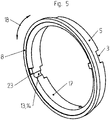
- the second sliding ring 5 is shown, with its second cooling channels 13, which form the derivations 14, with a damming edge 23 being arranged in each case in the circumferential direction 18 adjacent to the respective derivations 14 to partially increase the dynamic pressure in the cooling circuit 1.
Landscapes
- Engineering & Computer Science (AREA)
- General Engineering & Computer Science (AREA)
- Mechanical Engineering (AREA)
- Mechanical Sealing (AREA)
Claims (8)
- Garniture d'étanchéité à anneaux glissants comprenant un circuit de refroidissement (1) pouvant être traversé par un liquide et pourvu d'une entrée de liquide (2) et d'une sortie de liquide (3), un premier anneau glissant (4), un deuxième anneau glissant (5) disposé coaxialement au premier anneau glissant (4), et un anneau antagoniste (6), les anneaux glissants (4, 5) et l'anneau antagoniste (6) comportant chacun au moins une surface d'étanchéité (7, 8, 9, 10), l'au moins une surface d'étanchéité (7, 8) des anneaux glissants (4, 5) venant en appui étanche sur l'au moins une surface d'étanchéité (9, 10) de l'anneau antagoniste (6), le premier anneau glissant (4) comportant au moins un premier canal de refroidissement (11) qui est conçu comme un conduit d'alimentation (12) ou d'évacuation qui s'étend vers ou depuis les surfaces d'étanchéité (7, 8, 9, 10), le deuxième anneau glissant (5) comportant au moins un deuxième canal de refroidissement (13) qui est conçu comme un conduit d'évacuation (14) ou d'alimentation qui s'étend depuis ou vers les surfaces d'étanchéité (7, 8, 9, 10), le conduit d'alimentation (12) ou d'évacuation du premier anneau glissant (4) et le conduit d'évacuation (14) ou d'alimentation du deuxième anneau glissant (5) étant disposés sur les côtés circonférentiels (16, 17) dans la direction radiale (15) des anneaux glissants (4, 5) qui sont dirigés l'un vers l'autre et faisant partie intégrante de l'anneau glissant respectif (4, 5) et l'entrée de liquide (2) étant reliée fluidiquement au conduit d'alimentation (12) et la sortie de liquide (3) étant reliée fluidiquement au conduit d'évacuation (14), caractérisé en ce que les canaux de refroidissement (11, 13) sont chacun conçus sensiblement en forme de rainure et sont ouverts radialement en direction de l'autre anneau glissant respectif (5, 4).
- Garniture d'étanchéité à anneaux glissants selon la revendication 1, caractérisée en ce que chaque anneau glissant (4, 5) comporte au moins deux conduits d'alimentation (12) ou d'évacuation (14) qui sont répartis uniformément dans la direction circonférentielle (18).
- Garniture d'étanchéité à anneaux glissants selon la revendication 2, caractérisée en ce que les au moins deux conduits d'alimentation (12) d'un anneau glissant (4) sont associés par intervalle (19) aux au moins deux conduits d'évacuation (14) de l'autre anneau glissant (5), vu dans la direction circonférentielle (18).
- Garniture d'étanchéité à anneaux glissants selon l'une des revendications 1 à 3, caractérisée en ce que l'anneau antagoniste (6) comporte deux surfaces d'étanchéité (9, 10) dont l'une (9) vient en appui étanche sur la surface d'étanchéité (7) du premier anneau glissant (4) et l'une (10) vient en appui étanche sur la surface d'étanchéité (8) du deuxième anneau glissant (5).
- Garniture d'étanchéité à anneaux glissants selon la revendication 4, caractérisée en ce que les deux surfaces d'étanchéité (9, 10) de l'anneau antagoniste (6) sont associées de manière adjacente l'une à l'autre radialement à distance et en ce que les anneaux glissants (4, 5) et l'anneau antagoniste (6) délimitent un espace de refroidissement (20) sensiblement annulaire.
- Garniture d'étanchéité à anneaux glissants selon la revendication 5, caractérisée en ce qu'au moins une nervure de transport (22), qui s'étend dans la direction radiale (15), est disposée à travers l'interstice (21) formé par la distance.
- Garniture d'étanchéité à anneaux glissants selon la revendication 6, caractérisée en ce qu'au moins deux nervures de transport (22), uniformément réparties dans la direction circonférentielle (18), sont disposées dans l'interstice (21).
- Garniture d'étanchéité à anneaux glissants selon l'une des revendications 1 à 7, caractérisée en ce que l'anneau glissant (5), qui comporte le conduit d'évacuation (14), comporte un bord de retenue (23) de manière adjacente au conduit d'évacuation (14) dans la direction circonférentielle afin d'augmenter partiellement la pression de retenue dans le circuit de refroidissement (1).
Applications Claiming Priority (1)
| Application Number | Priority Date | Filing Date | Title |
|---|---|---|---|
| DE102018120039.0A DE102018120039B3 (de) | 2018-08-17 | 2018-08-17 | Gleitringdichtung |
Publications (2)
| Publication Number | Publication Date |
|---|---|
| EP3611407A1 EP3611407A1 (fr) | 2020-02-19 |
| EP3611407B1 true EP3611407B1 (fr) | 2022-06-08 |
Family
ID=67514327
Family Applications (1)
| Application Number | Title | Priority Date | Filing Date |
|---|---|---|---|
| EP19188821.3A Active EP3611407B1 (fr) | 2018-08-17 | 2019-07-29 | Joint d'étanchéité rotatif |
Country Status (2)
| Country | Link |
|---|---|
| EP (1) | EP3611407B1 (fr) |
| DE (1) | DE102018120039B3 (fr) |
Family Cites Families (4)
| Publication number | Priority date | Publication date | Assignee | Title |
|---|---|---|---|---|
| CH616994A5 (en) * | 1977-05-02 | 1980-04-30 | Asbest & Packungs Ag | Mechanical seal |
| GB2198488B (en) * | 1986-07-08 | 1991-03-13 | Sealol | Hydrostatic face seal and bearing |
| DE102009055637B4 (de) | 2009-11-25 | 2016-12-29 | Carl Freudenberg Kg | Gleitringdichtungsanordnung mit einem Einsatz zur Kühlflüssigkeitsführung |
| DE102009058341A1 (de) | 2009-12-15 | 2011-06-16 | Voith Patent Gmbh | Hydrodynamische Maschine, insbesondere hydrodynamischer Retarder |
-
2018
- 2018-08-17 DE DE102018120039.0A patent/DE102018120039B3/de active Active
-
2019
- 2019-07-29 EP EP19188821.3A patent/EP3611407B1/fr active Active
Also Published As
| Publication number | Publication date |
|---|---|
| EP3611407A1 (fr) | 2020-02-19 |
| DE102018120039B3 (de) | 2020-01-23 |
Similar Documents
| Publication | Publication Date | Title |
|---|---|---|
| DE112005000997B4 (de) | Gasdichtungseinrichtung | |
| EP2748495B1 (fr) | Système d'étanchéité à bagues de glissement refroidi | |
| DE102013211408B4 (de) | Kühleinrichtung zur Kühlung einer elektrischen Maschine und entsprechende elektrische Maschine mit Kühleinrichtung | |
| DE3039678A1 (de) | Gasdichtungsbuchse | |
| EP2169282A1 (fr) | Agencement doté d'un joint d'étanchéité d'arbre | |
| EP3963235B1 (fr) | Ensemble de garniture mécanique, en particulier pour des fluides chauds, ainsi qu'ensemble de pompe | |
| WO2009152991A1 (fr) | Agencement d'étanchéité à anneau glissant avec dispositif intégré de transfert thermique | |
| DE102018207842A1 (de) | Ein von einem Kühlmittel durchströmbarer Kühlmantel sowie eine mit einem solchen Kühlmantel ausgestattete elektrische Kraft- oder Arbeitsmaschine | |
| EP3123039B1 (fr) | Douille de refroidissement pour un palier et palier équipé d'une douille de refroidissement | |
| DE102016225523A1 (de) | Elektrische Maschine, Temperierungssystem und Verfahren zur Temperierung | |
| EP2182255B1 (fr) | Agencement de joints annulaires à brosses pour une turbomachine et turbomachine dotée d'un agencement de joints à brosses | |
| DE102017202038B4 (de) | Gleitringdichtungsanordnung mit Sicherheitsdichtung | |
| EP2470404B1 (fr) | Machine hydrodynamique, en particulier ralentisseur hydrodynamique | |
| EP3611407B1 (fr) | Joint d'étanchéité rotatif | |
| EP0690204B1 (fr) | Turbine à vapeur ayant au moins deux joint pour assurer l'étanchéité du carter | |
| DE2849256C3 (de) | Gleitringdichtung | |
| EP2535621B1 (fr) | Joint d'étanchéité pour arbre pour un système d'huile de blocage d'un générateur refroidi à l'hydrogène | |
| DE102016004936A1 (de) | Elektrische Maschine | |
| DE4401567C1 (de) | Wellendichtung | |
| EP3212972B1 (fr) | Manche d'arbre pour dispositif d'étanchéité et dispositif d'étanchéité de ce type | |
| EP3129604B1 (fr) | Machine avec un arbre et un palier | |
| WO2017162515A1 (fr) | Pompe centrifuge avec une garniture mécanique | |
| EP2764248B1 (fr) | Compresseur doté d'une rainure de décompression | |
| DE102024126634A1 (de) | Spiralverdichter | |
| DE112021008468T5 (de) | Elektrische Kraftfahrzeug-Seitenkanal-Flüssigkeitspumpe |
Legal Events
| Date | Code | Title | Description |
|---|---|---|---|
| PUAI | Public reference made under article 153(3) epc to a published international application that has entered the european phase |
Free format text: ORIGINAL CODE: 0009012 |
|
| STAA | Information on the status of an ep patent application or granted ep patent |
Free format text: STATUS: THE APPLICATION HAS BEEN PUBLISHED |
|
| AK | Designated contracting states |
Kind code of ref document: A1 Designated state(s): AL AT BE BG CH CY CZ DE DK EE ES FI FR GB GR HR HU IE IS IT LI LT LU LV MC MK MT NL NO PL PT RO RS SE SI SK SM TR |
|
| AX | Request for extension of the european patent |
Extension state: BA ME |
|
| STAA | Information on the status of an ep patent application or granted ep patent |
Free format text: STATUS: REQUEST FOR EXAMINATION WAS MADE |
|
| 17P | Request for examination filed |
Effective date: 20200520 |
|
| RBV | Designated contracting states (corrected) |
Designated state(s): AL AT BE BG CH CY CZ DE DK EE ES FI FR GB GR HR HU IE IS IT LI LT LU LV MC MK MT NL NO PL PT RO RS SE SI SK SM TR |
|
| GRAP | Despatch of communication of intention to grant a patent |
Free format text: ORIGINAL CODE: EPIDOSNIGR1 |
|
| STAA | Information on the status of an ep patent application or granted ep patent |
Free format text: STATUS: GRANT OF PATENT IS INTENDED |
|
| INTG | Intention to grant announced |
Effective date: 20220303 |
|
| GRAS | Grant fee paid |
Free format text: ORIGINAL CODE: EPIDOSNIGR3 |
|
| GRAA | (expected) grant |
Free format text: ORIGINAL CODE: 0009210 |
|
| STAA | Information on the status of an ep patent application or granted ep patent |
Free format text: STATUS: THE PATENT HAS BEEN GRANTED |
|
| AK | Designated contracting states |
Kind code of ref document: B1 Designated state(s): AL AT BE BG CH CY CZ DE DK EE ES FI FR GB GR HR HU IE IS IT LI LT LU LV MC MK MT NL NO PL PT RO RS SE SI SK SM TR |
|
| REG | Reference to a national code |
Ref country code: AT Ref legal event code: REF Ref document number: 1497148 Country of ref document: AT Kind code of ref document: T Effective date: 20220615 Ref country code: CH Ref legal event code: EP |
|
| REG | Reference to a national code |
Ref country code: DE Ref legal event code: R096 Ref document number: 502019004555 Country of ref document: DE |
|
| REG | Reference to a national code |
Ref country code: IE Ref legal event code: FG4D Free format text: LANGUAGE OF EP DOCUMENT: GERMAN |
|
| REG | Reference to a national code |
Ref country code: LT Ref legal event code: MG9D |
|
| REG | Reference to a national code |
Ref country code: NL Ref legal event code: MP Effective date: 20220608 |
|
| PG25 | Lapsed in a contracting state [announced via postgrant information from national office to epo] |
Ref country code: SE Free format text: LAPSE BECAUSE OF FAILURE TO SUBMIT A TRANSLATION OF THE DESCRIPTION OR TO PAY THE FEE WITHIN THE PRESCRIBED TIME-LIMIT Effective date: 20220608 Ref country code: NO Free format text: LAPSE BECAUSE OF FAILURE TO SUBMIT A TRANSLATION OF THE DESCRIPTION OR TO PAY THE FEE WITHIN THE PRESCRIBED TIME-LIMIT Effective date: 20220908 Ref country code: LT Free format text: LAPSE BECAUSE OF FAILURE TO SUBMIT A TRANSLATION OF THE DESCRIPTION OR TO PAY THE FEE WITHIN THE PRESCRIBED TIME-LIMIT Effective date: 20220608 Ref country code: HR Free format text: LAPSE BECAUSE OF FAILURE TO SUBMIT A TRANSLATION OF THE DESCRIPTION OR TO PAY THE FEE WITHIN THE PRESCRIBED TIME-LIMIT Effective date: 20220608 Ref country code: GR Free format text: LAPSE BECAUSE OF FAILURE TO SUBMIT A TRANSLATION OF THE DESCRIPTION OR TO PAY THE FEE WITHIN THE PRESCRIBED TIME-LIMIT Effective date: 20220909 Ref country code: FI Free format text: LAPSE BECAUSE OF FAILURE TO SUBMIT A TRANSLATION OF THE DESCRIPTION OR TO PAY THE FEE WITHIN THE PRESCRIBED TIME-LIMIT Effective date: 20220608 Ref country code: ES Free format text: LAPSE BECAUSE OF FAILURE TO SUBMIT A TRANSLATION OF THE DESCRIPTION OR TO PAY THE FEE WITHIN THE PRESCRIBED TIME-LIMIT Effective date: 20220608 Ref country code: BG Free format text: LAPSE BECAUSE OF FAILURE TO SUBMIT A TRANSLATION OF THE DESCRIPTION OR TO PAY THE FEE WITHIN THE PRESCRIBED TIME-LIMIT Effective date: 20220908 |
|
| PG25 | Lapsed in a contracting state [announced via postgrant information from national office to epo] |
Ref country code: RS Free format text: LAPSE BECAUSE OF FAILURE TO SUBMIT A TRANSLATION OF THE DESCRIPTION OR TO PAY THE FEE WITHIN THE PRESCRIBED TIME-LIMIT Effective date: 20220608 Ref country code: LV Free format text: LAPSE BECAUSE OF FAILURE TO SUBMIT A TRANSLATION OF THE DESCRIPTION OR TO PAY THE FEE WITHIN THE PRESCRIBED TIME-LIMIT Effective date: 20220608 |
|
| PG25 | Lapsed in a contracting state [announced via postgrant information from national office to epo] |
Ref country code: NL Free format text: LAPSE BECAUSE OF FAILURE TO SUBMIT A TRANSLATION OF THE DESCRIPTION OR TO PAY THE FEE WITHIN THE PRESCRIBED TIME-LIMIT Effective date: 20220608 |
|
| PG25 | Lapsed in a contracting state [announced via postgrant information from national office to epo] |
Ref country code: SM Free format text: LAPSE BECAUSE OF FAILURE TO SUBMIT A TRANSLATION OF THE DESCRIPTION OR TO PAY THE FEE WITHIN THE PRESCRIBED TIME-LIMIT Effective date: 20220608 Ref country code: SK Free format text: LAPSE BECAUSE OF FAILURE TO SUBMIT A TRANSLATION OF THE DESCRIPTION OR TO PAY THE FEE WITHIN THE PRESCRIBED TIME-LIMIT Effective date: 20220608 Ref country code: RO Free format text: LAPSE BECAUSE OF FAILURE TO SUBMIT A TRANSLATION OF THE DESCRIPTION OR TO PAY THE FEE WITHIN THE PRESCRIBED TIME-LIMIT Effective date: 20220608 Ref country code: PT Free format text: LAPSE BECAUSE OF FAILURE TO SUBMIT A TRANSLATION OF THE DESCRIPTION OR TO PAY THE FEE WITHIN THE PRESCRIBED TIME-LIMIT Effective date: 20221010 Ref country code: EE Free format text: LAPSE BECAUSE OF FAILURE TO SUBMIT A TRANSLATION OF THE DESCRIPTION OR TO PAY THE FEE WITHIN THE PRESCRIBED TIME-LIMIT Effective date: 20220608 Ref country code: CZ Free format text: LAPSE BECAUSE OF FAILURE TO SUBMIT A TRANSLATION OF THE DESCRIPTION OR TO PAY THE FEE WITHIN THE PRESCRIBED TIME-LIMIT Effective date: 20220608 |
|
| PG25 | Lapsed in a contracting state [announced via postgrant information from national office to epo] |
Ref country code: PL Free format text: LAPSE BECAUSE OF FAILURE TO SUBMIT A TRANSLATION OF THE DESCRIPTION OR TO PAY THE FEE WITHIN THE PRESCRIBED TIME-LIMIT Effective date: 20220608 Ref country code: IS Free format text: LAPSE BECAUSE OF FAILURE TO SUBMIT A TRANSLATION OF THE DESCRIPTION OR TO PAY THE FEE WITHIN THE PRESCRIBED TIME-LIMIT Effective date: 20221008 |
|
| REG | Reference to a national code |
Ref country code: CH Ref legal event code: PL |
|
| REG | Reference to a national code |
Ref country code: DE Ref legal event code: R097 Ref document number: 502019004555 Country of ref document: DE |
|
| REG | Reference to a national code |
Ref country code: BE Ref legal event code: MM Effective date: 20220731 |
|
| PG25 | Lapsed in a contracting state [announced via postgrant information from national office to epo] |
Ref country code: MC Free format text: LAPSE BECAUSE OF FAILURE TO SUBMIT A TRANSLATION OF THE DESCRIPTION OR TO PAY THE FEE WITHIN THE PRESCRIBED TIME-LIMIT Effective date: 20220608 Ref country code: AL Free format text: LAPSE BECAUSE OF FAILURE TO SUBMIT A TRANSLATION OF THE DESCRIPTION OR TO PAY THE FEE WITHIN THE PRESCRIBED TIME-LIMIT Effective date: 20220608 |
|
| PLBE | No opposition filed within time limit |
Free format text: ORIGINAL CODE: 0009261 |
|
| STAA | Information on the status of an ep patent application or granted ep patent |
Free format text: STATUS: NO OPPOSITION FILED WITHIN TIME LIMIT |
|
| PG25 | Lapsed in a contracting state [announced via postgrant information from national office to epo] |
Ref country code: LU Free format text: LAPSE BECAUSE OF NON-PAYMENT OF DUE FEES Effective date: 20220729 Ref country code: LI Free format text: LAPSE BECAUSE OF NON-PAYMENT OF DUE FEES Effective date: 20220731 Ref country code: DK Free format text: LAPSE BECAUSE OF FAILURE TO SUBMIT A TRANSLATION OF THE DESCRIPTION OR TO PAY THE FEE WITHIN THE PRESCRIBED TIME-LIMIT Effective date: 20220608 Ref country code: CH Free format text: LAPSE BECAUSE OF NON-PAYMENT OF DUE FEES Effective date: 20220731 |
|
| 26N | No opposition filed |
Effective date: 20230310 |
|
| PG25 | Lapsed in a contracting state [announced via postgrant information from national office to epo] |
Ref country code: SI Free format text: LAPSE BECAUSE OF FAILURE TO SUBMIT A TRANSLATION OF THE DESCRIPTION OR TO PAY THE FEE WITHIN THE PRESCRIBED TIME-LIMIT Effective date: 20220608 Ref country code: BE Free format text: LAPSE BECAUSE OF NON-PAYMENT OF DUE FEES Effective date: 20220731 |
|
| PG25 | Lapsed in a contracting state [announced via postgrant information from national office to epo] |
Ref country code: IE Free format text: LAPSE BECAUSE OF NON-PAYMENT OF DUE FEES Effective date: 20220729 Ref country code: FR Free format text: LAPSE BECAUSE OF NON-PAYMENT OF DUE FEES Effective date: 20220808 |
|
| PG25 | Lapsed in a contracting state [announced via postgrant information from national office to epo] |
Ref country code: IT Free format text: LAPSE BECAUSE OF FAILURE TO SUBMIT A TRANSLATION OF THE DESCRIPTION OR TO PAY THE FEE WITHIN THE PRESCRIBED TIME-LIMIT Effective date: 20220608 |
|
| GBPC | Gb: european patent ceased through non-payment of renewal fee |
Effective date: 20230729 |
|
| PG25 | Lapsed in a contracting state [announced via postgrant information from national office to epo] |
Ref country code: HU Free format text: LAPSE BECAUSE OF FAILURE TO SUBMIT A TRANSLATION OF THE DESCRIPTION OR TO PAY THE FEE WITHIN THE PRESCRIBED TIME-LIMIT; INVALID AB INITIO Effective date: 20190729 |
|
| PG25 | Lapsed in a contracting state [announced via postgrant information from national office to epo] |
Ref country code: MK Free format text: LAPSE BECAUSE OF FAILURE TO SUBMIT A TRANSLATION OF THE DESCRIPTION OR TO PAY THE FEE WITHIN THE PRESCRIBED TIME-LIMIT Effective date: 20220608 Ref country code: CY Free format text: LAPSE BECAUSE OF FAILURE TO SUBMIT A TRANSLATION OF THE DESCRIPTION OR TO PAY THE FEE WITHIN THE PRESCRIBED TIME-LIMIT Effective date: 20220608 Ref country code: GB Free format text: LAPSE BECAUSE OF NON-PAYMENT OF DUE FEES Effective date: 20230729 |
|
| PG25 | Lapsed in a contracting state [announced via postgrant information from national office to epo] |
Ref country code: MT Free format text: LAPSE BECAUSE OF FAILURE TO SUBMIT A TRANSLATION OF THE DESCRIPTION OR TO PAY THE FEE WITHIN THE PRESCRIBED TIME-LIMIT Effective date: 20220608 |
|
| PG25 | Lapsed in a contracting state [announced via postgrant information from national office to epo] |
Ref country code: BG Free format text: LAPSE BECAUSE OF FAILURE TO SUBMIT A TRANSLATION OF THE DESCRIPTION OR TO PAY THE FEE WITHIN THE PRESCRIBED TIME-LIMIT Effective date: 20220608 |
|
| PG25 | Lapsed in a contracting state [announced via postgrant information from national office to epo] |
Ref country code: BG Free format text: LAPSE BECAUSE OF FAILURE TO SUBMIT A TRANSLATION OF THE DESCRIPTION OR TO PAY THE FEE WITHIN THE PRESCRIBED TIME-LIMIT Effective date: 20220608 |
|
| REG | Reference to a national code |
Ref country code: AT Ref legal event code: MM01 Ref document number: 1497148 Country of ref document: AT Kind code of ref document: T Effective date: 20240729 |
|
| PGFP | Annual fee paid to national office [announced via postgrant information from national office to epo] |
Ref country code: DE Payment date: 20250728 Year of fee payment: 7 |
|
| PG25 | Lapsed in a contracting state [announced via postgrant information from national office to epo] |
Ref country code: AT Free format text: LAPSE BECAUSE OF NON-PAYMENT OF DUE FEES Effective date: 20240729 |
|
| PG25 | Lapsed in a contracting state [announced via postgrant information from national office to epo] |
Ref country code: TR Free format text: LAPSE BECAUSE OF FAILURE TO SUBMIT A TRANSLATION OF THE DESCRIPTION OR TO PAY THE FEE WITHIN THE PRESCRIBED TIME-LIMIT Effective date: 20220608 |
|
| PGFP | Annual fee paid to national office [announced via postgrant information from national office to epo] |
Ref country code: AT Payment date: 20260410 Year of fee payment: 5 |