EP3611491A1 - Procédé optomagnétophorétique pour la détection de substances biologiques et chimiques - Google Patents
Procédé optomagnétophorétique pour la détection de substances biologiques et chimiques Download PDFInfo
- Publication number
- EP3611491A1 EP3611491A1 EP18762119.8A EP18762119A EP3611491A1 EP 3611491 A1 EP3611491 A1 EP 3611491A1 EP 18762119 A EP18762119 A EP 18762119A EP 3611491 A1 EP3611491 A1 EP 3611491A1
- Authority
- EP
- European Patent Office
- Prior art keywords
- magnetic
- particles
- suspension
- transparency
- magnetic force
- Prior art date
- Legal status (The legal status is an assumption and is not a legal conclusion. Google has not performed a legal analysis and makes no representation as to the accuracy of the status listed.)
- Granted
Links
Images



Classifications
-
- G—PHYSICS
- G01—MEASURING; TESTING
- G01N—INVESTIGATING OR ANALYSING MATERIALS BY DETERMINING THEIR CHEMICAL OR PHYSICAL PROPERTIES
- G01N35/00—Automatic analysis not limited to methods or materials provided for in any single one of groups G01N1/00 - G01N33/00; Handling materials therefor
- G01N35/0098—Automatic analysis not limited to methods or materials provided for in any single one of groups G01N1/00 - G01N33/00; Handling materials therefor involving analyte bound to insoluble magnetic carrier, e.g. using magnetic separation
-
- B—PERFORMING OPERATIONS; TRANSPORTING
- B03—SEPARATION OF SOLID MATERIALS USING LIQUIDS OR USING PNEUMATIC TABLES OR JIGS; MAGNETIC OR ELECTROSTATIC SEPARATION OF SOLID MATERIALS FROM SOLID MATERIALS OR FLUIDS; SEPARATION BY HIGH-VOLTAGE ELECTRIC FIELDS
- B03C—MAGNETIC OR ELECTROSTATIC SEPARATION OF SOLID MATERIALS FROM SOLID MATERIALS OR FLUIDS; SEPARATION BY HIGH-VOLTAGE ELECTRIC FIELDS
- B03C1/00—Magnetic separation
- B03C1/005—Pretreatment specially adapted for magnetic separation
- B03C1/01—Pretreatment specially adapted for magnetic separation by addition of magnetic adjuvants
-
- B—PERFORMING OPERATIONS; TRANSPORTING
- B03—SEPARATION OF SOLID MATERIALS USING LIQUIDS OR USING PNEUMATIC TABLES OR JIGS; MAGNETIC OR ELECTROSTATIC SEPARATION OF SOLID MATERIALS FROM SOLID MATERIALS OR FLUIDS; SEPARATION BY HIGH-VOLTAGE ELECTRIC FIELDS
- B03C—MAGNETIC OR ELECTROSTATIC SEPARATION OF SOLID MATERIALS FROM SOLID MATERIALS OR FLUIDS; SEPARATION BY HIGH-VOLTAGE ELECTRIC FIELDS
- B03C1/00—Magnetic separation
- B03C1/02—Magnetic separation acting directly on the substance being separated
- B03C1/025—High gradient magnetic separators
- B03C1/031—Component parts; Auxiliary operations
- B03C1/033—Component parts; Auxiliary operations characterised by the magnetic circuit
- B03C1/0332—Component parts; Auxiliary operations characterised by the magnetic circuit using permanent magnets
-
- B—PERFORMING OPERATIONS; TRANSPORTING
- B03—SEPARATION OF SOLID MATERIALS USING LIQUIDS OR USING PNEUMATIC TABLES OR JIGS; MAGNETIC OR ELECTROSTATIC SEPARATION OF SOLID MATERIALS FROM SOLID MATERIALS OR FLUIDS; SEPARATION BY HIGH-VOLTAGE ELECTRIC FIELDS
- B03C—MAGNETIC OR ELECTROSTATIC SEPARATION OF SOLID MATERIALS FROM SOLID MATERIALS OR FLUIDS; SEPARATION BY HIGH-VOLTAGE ELECTRIC FIELDS
- B03C1/00—Magnetic separation
- B03C1/02—Magnetic separation acting directly on the substance being separated
- B03C1/28—Magnetic plugs and dipsticks
- B03C1/288—Magnetic plugs and dipsticks disposed at the outer circumference of a recipient
-
- B—PERFORMING OPERATIONS; TRANSPORTING
- B03—SEPARATION OF SOLID MATERIALS USING LIQUIDS OR USING PNEUMATIC TABLES OR JIGS; MAGNETIC OR ELECTROSTATIC SEPARATION OF SOLID MATERIALS FROM SOLID MATERIALS OR FLUIDS; SEPARATION BY HIGH-VOLTAGE ELECTRIC FIELDS
- B03C—MAGNETIC OR ELECTROSTATIC SEPARATION OF SOLID MATERIALS FROM SOLID MATERIALS OR FLUIDS; SEPARATION BY HIGH-VOLTAGE ELECTRIC FIELDS
- B03C1/00—Magnetic separation
- B03C1/02—Magnetic separation acting directly on the substance being separated
- B03C1/30—Combinations with other devices, not otherwise provided for
-
- B—PERFORMING OPERATIONS; TRANSPORTING
- B03—SEPARATION OF SOLID MATERIALS USING LIQUIDS OR USING PNEUMATIC TABLES OR JIGS; MAGNETIC OR ELECTROSTATIC SEPARATION OF SOLID MATERIALS FROM SOLID MATERIALS OR FLUIDS; SEPARATION BY HIGH-VOLTAGE ELECTRIC FIELDS
- B03C—MAGNETIC OR ELECTROSTATIC SEPARATION OF SOLID MATERIALS FROM SOLID MATERIALS OR FLUIDS; SEPARATION BY HIGH-VOLTAGE ELECTRIC FIELDS
- B03C1/00—Magnetic separation
- B03C1/32—Magnetic separation acting on the medium containing the substance being separated, e.g. magneto-gravimetric-, magnetohydrostatic-, or magnetohydrodynamic separation
-
- G—PHYSICS
- G01—MEASURING; TESTING
- G01N—INVESTIGATING OR ANALYSING MATERIALS BY DETERMINING THEIR CHEMICAL OR PHYSICAL PROPERTIES
- G01N15/00—Investigating characteristics of particles; Investigating permeability, pore-volume or surface-area of porous materials
- G01N15/02—Investigating particle size or size distribution
-
- G—PHYSICS
- G01—MEASURING; TESTING
- G01N—INVESTIGATING OR ANALYSING MATERIALS BY DETERMINING THEIR CHEMICAL OR PHYSICAL PROPERTIES
- G01N21/00—Investigating or analysing materials by the use of optical means, i.e. using sub-millimetre waves, infrared, visible or ultraviolet light
- G01N21/17—Systems in which incident light is modified in accordance with the properties of the material investigated
- G01N21/59—Transmissivity
-
- G—PHYSICS
- G01—MEASURING; TESTING
- G01N—INVESTIGATING OR ANALYSING MATERIALS BY DETERMINING THEIR CHEMICAL OR PHYSICAL PROPERTIES
- G01N21/00—Investigating or analysing materials by the use of optical means, i.e. using sub-millimetre waves, infrared, visible or ultraviolet light
- G01N21/75—Systems in which material is subjected to a chemical reaction, the progress or the result of the reaction being investigated
- G01N21/77—Systems in which material is subjected to a chemical reaction, the progress or the result of the reaction being investigated by observing the effect on a chemical indicator
- G01N21/82—Systems in which material is subjected to a chemical reaction, the progress or the result of the reaction being investigated by observing the effect on a chemical indicator producing a precipitate or turbidity
-
- B—PERFORMING OPERATIONS; TRANSPORTING
- B01—PHYSICAL OR CHEMICAL PROCESSES OR APPARATUS IN GENERAL
- B01L—CHEMICAL OR PHYSICAL LABORATORY APPARATUS FOR GENERAL USE
- B01L3/00—Containers or dishes for laboratory use, e.g. laboratory glassware; Droppers
- B01L3/50—Containers for the purpose of retaining a material to be analysed, e.g. test tubes
- B01L3/502—Containers for the purpose of retaining a material to be analysed, e.g. test tubes with fluid transport, e.g. in multi-compartment structures
- B01L3/5027—Containers for the purpose of retaining a material to be analysed, e.g. test tubes with fluid transport, e.g. in multi-compartment structures by integrated microfluidic structures, i.e. dimensions of channels and chambers are such that surface tension forces are important, e.g. lab-on-a-chip
- B01L3/502761—Containers for the purpose of retaining a material to be analysed, e.g. test tubes with fluid transport, e.g. in multi-compartment structures by integrated microfluidic structures, i.e. dimensions of channels and chambers are such that surface tension forces are important, e.g. lab-on-a-chip specially adapted for handling suspended solids or molecules independently from the bulk fluid flow, e.g. for trapping or sorting beads or physically stretching molecules
-
- B—PERFORMING OPERATIONS; TRANSPORTING
- B03—SEPARATION OF SOLID MATERIALS USING LIQUIDS OR USING PNEUMATIC TABLES OR JIGS; MAGNETIC OR ELECTROSTATIC SEPARATION OF SOLID MATERIALS FROM SOLID MATERIALS OR FLUIDS; SEPARATION BY HIGH-VOLTAGE ELECTRIC FIELDS
- B03C—MAGNETIC OR ELECTROSTATIC SEPARATION OF SOLID MATERIALS FROM SOLID MATERIALS OR FLUIDS; SEPARATION BY HIGH-VOLTAGE ELECTRIC FIELDS
- B03C2201/00—Details of magnetic or electrostatic separation
- B03C2201/18—Magnetic separation whereby the particles are suspended in a liquid
-
- B—PERFORMING OPERATIONS; TRANSPORTING
- B03—SEPARATION OF SOLID MATERIALS USING LIQUIDS OR USING PNEUMATIC TABLES OR JIGS; MAGNETIC OR ELECTROSTATIC SEPARATION OF SOLID MATERIALS FROM SOLID MATERIALS OR FLUIDS; SEPARATION BY HIGH-VOLTAGE ELECTRIC FIELDS
- B03C—MAGNETIC OR ELECTROSTATIC SEPARATION OF SOLID MATERIALS FROM SOLID MATERIALS OR FLUIDS; SEPARATION BY HIGH-VOLTAGE ELECTRIC FIELDS
- B03C2201/00—Details of magnetic or electrostatic separation
- B03C2201/22—Details of magnetic or electrostatic separation characterised by the magnetic field, e.g. its shape or generation
-
- B—PERFORMING OPERATIONS; TRANSPORTING
- B03—SEPARATION OF SOLID MATERIALS USING LIQUIDS OR USING PNEUMATIC TABLES OR JIGS; MAGNETIC OR ELECTROSTATIC SEPARATION OF SOLID MATERIALS FROM SOLID MATERIALS OR FLUIDS; SEPARATION BY HIGH-VOLTAGE ELECTRIC FIELDS
- B03C—MAGNETIC OR ELECTROSTATIC SEPARATION OF SOLID MATERIALS FROM SOLID MATERIALS OR FLUIDS; SEPARATION BY HIGH-VOLTAGE ELECTRIC FIELDS
- B03C2201/00—Details of magnetic or electrostatic separation
- B03C2201/26—Details of magnetic or electrostatic separation for use in medical or biological applications
-
- B—PERFORMING OPERATIONS; TRANSPORTING
- B82—NANOTECHNOLOGY
- B82Y—SPECIFIC USES OR APPLICATIONS OF NANOSTRUCTURES; MEASUREMENT OR ANALYSIS OF NANOSTRUCTURES; MANUFACTURE OR TREATMENT OF NANOSTRUCTURES
- B82Y25/00—Nanomagnetism, e.g. magnetoimpedance, anisotropic magnetoresistance, giant magnetoresistance or tunneling magnetoresistance
-
- B—PERFORMING OPERATIONS; TRANSPORTING
- B82—NANOTECHNOLOGY
- B82Y—SPECIFIC USES OR APPLICATIONS OF NANOSTRUCTURES; MEASUREMENT OR ANALYSIS OF NANOSTRUCTURES; MANUFACTURE OR TREATMENT OF NANOSTRUCTURES
- B82Y35/00—Methods or apparatus for measurement or analysis of nanostructures
-
- B—PERFORMING OPERATIONS; TRANSPORTING
- B82—NANOTECHNOLOGY
- B82Y—SPECIFIC USES OR APPLICATIONS OF NANOSTRUCTURES; MEASUREMENT OR ANALYSIS OF NANOSTRUCTURES; MANUFACTURE OR TREATMENT OF NANOSTRUCTURES
- B82Y5/00—Nanobiotechnology or nanomedicine, e.g. protein engineering or drug delivery
-
- G—PHYSICS
- G01—MEASURING; TESTING
- G01N—INVESTIGATING OR ANALYSING MATERIALS BY DETERMINING THEIR CHEMICAL OR PHYSICAL PROPERTIES
- G01N15/00—Investigating characteristics of particles; Investigating permeability, pore-volume or surface-area of porous materials
- G01N15/06—Investigating concentration of particle suspensions
- G01N15/075—Investigating concentration of particle suspensions by optical means
-
- G—PHYSICS
- G01—MEASURING; TESTING
- G01N—INVESTIGATING OR ANALYSING MATERIALS BY DETERMINING THEIR CHEMICAL OR PHYSICAL PROPERTIES
- G01N15/00—Investigating characteristics of particles; Investigating permeability, pore-volume or surface-area of porous materials
- G01N2015/0092—Monitoring flocculation or agglomeration
-
- G—PHYSICS
- G01—MEASURING; TESTING
- G01N—INVESTIGATING OR ANALYSING MATERIALS BY DETERMINING THEIR CHEMICAL OR PHYSICAL PROPERTIES
- G01N15/00—Investigating characteristics of particles; Investigating permeability, pore-volume or surface-area of porous materials
- G01N15/02—Investigating particle size or size distribution
- G01N2015/0277—Average size only
-
- G—PHYSICS
- G01—MEASURING; TESTING
- G01N—INVESTIGATING OR ANALYSING MATERIALS BY DETERMINING THEIR CHEMICAL OR PHYSICAL PROPERTIES
- G01N21/00—Investigating or analysing materials by the use of optical means, i.e. using sub-millimetre waves, infrared, visible or ultraviolet light
- G01N21/75—Systems in which material is subjected to a chemical reaction, the progress or the result of the reaction being investigated
- G01N21/77—Systems in which material is subjected to a chemical reaction, the progress or the result of the reaction being investigated by observing the effect on a chemical indicator
- G01N21/82—Systems in which material is subjected to a chemical reaction, the progress or the result of the reaction being investigated by observing the effect on a chemical indicator producing a precipitate or turbidity
- G01N2021/825—Agglutination
-
- G—PHYSICS
- G01—MEASURING; TESTING
- G01N—INVESTIGATING OR ANALYSING MATERIALS BY DETERMINING THEIR CHEMICAL OR PHYSICAL PROPERTIES
- G01N33/00—Investigating or analysing materials by specific methods not covered by groups G01N1/00 - G01N31/00
- G01N33/48—Biological material, e.g. blood, urine; Haemocytometers
- G01N33/50—Chemical analysis of biological material, e.g. blood, urine; Testing involving biospecific ligand binding methods; Immunological testing
- G01N33/53—Immunoassay; Biospecific binding assay; Materials therefor
- G01N33/543—Immunoassay; Biospecific binding assay; Materials therefor with an insoluble carrier for immobilising immunochemicals
- G01N33/54313—Immunoassay; Biospecific binding assay; Materials therefor with an insoluble carrier for immobilising immunochemicals the carrier being characterised by its particulate form
- G01N33/54326—Magnetic particles
Definitions
- the present invention relates to a method for substance (organic, inorganic or biological) detection.
- the invention uses a novel magnetophoresis technique wherein materials in a sample are mixed with functionalized magnetic particles, such that the variation of the optical properties versus time are monitored and compared with the time-variation in absence of the targeted biological or chemical substance.
- This aggregation is mediated by the specific reaction between two molecules, such us antibodies and antigens, one of which is immobilized on the surface of the latex particles to enhance the sensitivity and extend the point of equivalence.
- a fluid containing the ligand of interest is introduced into a suspension of the sensitized carrier particles, and the agglutination is noted as indicative of the ligand.
- the agglutination reaction may be used in several different modes to detect the ligand of interest, and each has its own limitations and applications. There are a number of techniques based on light scattering phenomena to detect latex particles' agglutination: turbidimetry, nephelometry, angular anisotropy, and photon correlation spectroscopy.
- Turbidimetry involves measurement of the intensity of the incident beam as it passes through the sample.
- the light beam may pass through a suspension or be absorbed, reflected, or scattered by the particles.
- the intensity of light decreases as it propagates through the suspension.
- the decrease in light intensity due to scattering is expressed as turbidity. This technique is rapid and easy to use. In fact turbidimetry does not require any special equipment other than a spectrophotometer, which is generally available in clinical laboratories.
- particles of smaller diameter may yield more robust assays.
- particles to agglutinate they must first collide so that antigen-antibody bridges can form.
- diffusion is fast enough to produce the initial collisions necessary for aggregate formation. If the particles are large diffusion is reduced (i.e., the agglutination kinetics) because the diffusion coefficient is inversely proportional to particle size. Small particles are desirable because of the requirement for increasing the collision frequency between particles or aggregates to enhance the rate of immunoaggregate production.
- the turbidimetric detection depends strongly on the particle size and the incident light wavelength. It is important to select carefully the suitable particles (size) for a suitable wavelength, since the turbidity reaches a maximum with time. This maximum occurs when the signal change exceeds the optical limits of the measuring system. It has been observed by photon correlation spectroscopy that changes in aggregates size continue beyond the plateau observed in turbidimetric assays.
- the optimal performance may be a function of the ratio of the particle diameter to the incident wavelength, and the refractive index of particle.
- the scattering increases with the inverse fourth power of the wavelength. Shorter wavelengths, such as 340 nm, give larger signal differences during agglutination than longer wavelengths, such as 450 nm.
- the higher the refractive index of the particles at the wavelength of choice the higher the light scattering signal.
- the refractive index of a material is greater at shorter wavelengths.
- Particles with a polyvinylnaphthalene core have been proposed to enhance sensitivity of latex immunoagglutination assays. Galvin et al. claimed that for the lowest detection limits particles should be in the size range 40-70 nm, with a high refractive index but low absorbance at the wavelength of light used.
- Magnetic particles Those magnetic nanospheres and microspheres containing superparamagnetic cores in a nonmagnetic matrix (hereafter magnetic particles) are used in numerous biological applications. They are used, for example, as carriers, which can be targeted to a particular site using an external magnetic field.
- the above mentioned magnetic particles are designed to create magnetic particles with large superparamagnetic response.
- these magnetic particles are typically made by embedding superparamagnetic nanocrystals in a non-magnetic matrix such as polystyrene and nanoporous silica.
- the resulting magnetic particles retain the superparamagnetic response of their constituent superparamagnetic nanocrystals and show larger magnetization when an external magnetic field is applied. Further, neither coercivity nor remanence is observed at the working temperature.
- Biomagnetic Separation (using the magnetic particles described above) has numerous applications in Life Science. From cell sorting to molecular diagnostics, this technology can be used with volumes ranging from a few nanoliters (lab-on-chip) to tens of liters (production of IVD-reagents).
- One of the problems of working with small tubes and classical magnetic separators (or simple magnets) is the lack of definition of the magnetic force. As the magnetic field and its gradient change with distance, the force on the magnetic particle in the suspension is not constant and variations in the behavior of the suspension are difficult to control.
- EP0339623 discloses a laser magnetic immunoassay method and system based on antigen-antibody reactions. For this method, nano beads are needed and electromagnets are used to generate the magnetic force.
- the use of magnetic nanoparticles (D ⁇ 100 nm) implies that its magnetic moment is very small, thus each particle moves without interacting magnetically with its neighbors.
- This individual magnetophoretic behavior implies a slow separation speed and a strong dependence on the individual nanobeads characteristics.
- the value of the magnetic force over an individual magnetic nanobead would depend on the value of the applied intensity on electromagnet, but would be different if the current is increasing or decreasing, and if the pole pieces have been saturated or not (i.e. the applied electrical current have reach a value high enough to reach the maximal magnetization of the pole pieces' material). All these effects imply that for a given set of individual beads, its a large variation on the time needed for reaching the final position (or any specific point), and even for exactly the same distribution of physical characteristics (size, density, magnetic properties), reproducibility would require a precise electrical current control and detailed control on how it is applied to the electromagnet.
- the present invention provides a method for detecting the presence or absence of a biological or chemical substance based on a opto-magnetophoresis technique, wherein the materials are reacted with functionalized magnetic particles in the range of 10-1000 nm in the presence of a uniform magnetic field gradient.
- the method does not depend on the refractive index of the non-magnetic matrix of the magnetic particles, as in known turbidimetric techniques, and the device does not need a laser or electromagnets, the invention solving thus the problems discussed above.
- the method comprises the steps of providing a light source and detector, providing a magnetic force perpendicular to the light's propagation direction with a constant magnetic field gradient, with an absolute value which is higher than 0.1 T, and measuring the change of the magnetic particle's suspension transparency versus time.
- Systems for putting the invention into practice comprise a light source and detector, a magnetic force generator made of permanent magnets for generating a magnetic force perpendicular to the light's propagation direction, with a constant magnetic field gradient and with an absolute value which is higher than 0.1 T and processing means for measuring the change of the magnetic particle's suspension transparency versus time.
- the magnetic force generator is formed by at least four permanent magnets following the Halbach progression for a quadrupole in a cylindrical support.
- the magnetic force generator is formed by two permanent magnets with opposite polarities and the light and the detector is an spectrophotometer.
- materials in a sample are reacted with magnetic particles (commercially available) that are functionalized to specifically bind to the targeted biological material in solution to produce a magnetic colloidal aggregate.
- the magnetic particles can be coated with protein antigens and reacted with the corresponding antibody, or with complementary or non-complementary oligonucleotides for genetic and pathogenic disease-detection.
- Other aggregations are based on electrostatic interaction between the magnetic particles and the biological materials, or by the absorption of the material onto the surface of the magnetic particles.
- the magnetic particles are absorbed on the surface of the microorganism.
- the aggregate is driven by magnetic forces towards the walls of the transparent vessel containing the suspension inducing higher transparency in the suspension.
- the progressive transparency of the suspension is real-time monitored.
- the separation speed in the present invention depends on the magnetization and size of the particles. These parameters can be adjusted by adjusting the size and the magnetic content of particles.
- the most suitable particles for use with the invention are particles of 200-300 nm of diameter with a magnetic content of 20-60%.
- colloidal aggregates containing the magnetic particles and the analyte are formed. Those aggregates, when brought under a uniform magnetic field gradient, move at a higher velocity than the initial monodispersed magnetic particles (colloids without analyte). As described by Andreu et al ( J. S.
- the movement of magnetic particles is a cooperative phenomenon where the individual particle has enough magnetic moment for having a magnetic dipole-dipole interaction with its neighbours, strong enough to overcome thermal agitation. If that happens, the magnetic particles form chains moving much faster than isolated magnetic particles.
- the magnetic particles interact and move much faster than when N ⁇ 1 and each particle moves isolated.
- selecting the right diameter and saturation magnetisation for the selected magnetic particle it is possible to have it moving as an isolated particle (slow) when is not agglutinated, but moving cooperatively (fast) when its agglutinated.
- the particles linked through reaction with the analyte act as particles having a bigger diameter. It should be noticed that the increase in diameter has a larger effect on the value of ⁇ (even if the effective Ms would be lower for the agglutinate) and its effect over N is exponential.
- This behavior induces an important difference in the magnetic separation time of the formed aggregates and the monodispersed magnetic particles.
- This difference in magnetic separation time is optically monitored by measuring the real time transparency of the suspension.
- the suspension reaches higher grades of transparency in shorter times in comparison with the suspension of the monodispersed magnetic particles.
- This optical monitoring can be performed in white light (combination of different wavelengths in the electromagnetic spectrum), or at specific wavelengths such as the UV-Visible spectrum (350nm, 580nm,).
- Optical monitoring at a specific wavelength has an additional advantage over the optical monitoring using white light, as it allows the detection of aggregates at concentrations as low as 0.001%.
- the aggregates concentrate at the walls of the transparent vessel, in the region where the magnetic field is maximum, this behavior allows their collection for further analysis.
- the particle characteristics and incident light wavelength should be carefully chosen to avoid to excess the optical limits of the measuring system. In comparison, in the present invention, it is not necessary to select particles for a suitable wavelength.
- the aggregates are magnetic and are removed by the magnetic force from the suspension, the results of the experiments do not depend on the interaction of the incident light with the aggregate.
- many types of magnetic particles can be used (composites of iron oxide nanoparticles embedded in non-magnetic matrices).
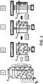
- Figs. 1a and 1b show a lateral and top view of the magnetophoresis process according to the invention.
- the light propagates in a perpendicular direction to the magnetic force (F mag ) across the suspension to reach the optical detector placed at the other side of the transparent vessel.
- F mag the magnetic force
- the homogeneously dispersed aggregates start moving towards the vessel wall due to the magnetic force (F mag ).
- F mag the magnetic force
- All the magnetic particles are close to the vessel wall and the suspension becomes transparent to the incident light.
- the transmitted light is detected by an optical detector indicating the end of the separation process.
- a constant magnetic force is generated on the whole sample volume.
- the magnetic force must be perpendicular to the light's propagation direction.
- the magnetic force acting over the magnetic particles is the gradient of the product of the magnetic moment by the applied magnetic field. If the magnetic moment of the particles is constant, the force is constant when the magnetic field gradient is also constant. At the same time, the magnetic moment of the particles depends on the applied magnetic field. When the applied field is small, the magnetic moment is proportional to the latter.
- the resultant magnetic moment is then the product of the volume (or mass) of the particle by the value of the magnetization of the magnetic nanoparticles embedded in the non-magnetic matrix (magnetic particles).
- the magnetization is the product of the magnetic susceptibility (a constant which is intrinsic to the material) multiplied by the applied field.
- the magnetization When the magnetic field reaches a particular value, the magnetization remains almost constant, i.e. becomes saturated, and the magnetic moment of each particle is constant.
- saturation field B s .
- the magnetic force generator according to the invention is a magnetic field source that generates a magnetic field with a constant gradient and absolute value higher than the saturation field in the region where the samples are placed for measuring the transparency changes. For practical purposes, a 0.1T field is sufficient to guarantee the saturation of any commercial particles suitable for use with the invention.
- the speed of the magnetic particles placed at the sample holder is the result of the competition between the magnetic force and the drag force generated by the viscosity of the buffer suspension. The speed resultant of the balance of these force is proportional to the square of the magnetic bead diameter, the gradient of the applied magnetic field, the magnetization and the density of the particle, and it is inversely proportional to the buffer viscosity.
- the separation speed is thus faster due the larger diameter.
- the aggregates act as larger particles and move therefore faster than the single particles.
- magnetic field gradients between 1 T/m and 100 T/m are needed over large volumes if the separation is to be performed in few minutes and not in several hours. These gradients (on relatively large gaps) are very difficult to obtain with electromagnets due to the limitations inherent to the use of soft ferromagnetic pole pieces.
- the optical means can be as simple as a LED that generates the light, and a detector such as a photodiode or a light dependent resistor that measures the amount of light transmitted through the sample.
- a detector such as a photodiode or a light dependent resistor that measures the amount of light transmitted through the sample.
- This simple arrangement allows to place one sample with its own light source and detector to measure a single analyte, or several samples (each with its own light source and detector) inside a cylindrical cavity, allowing a multiplex or mid-plex assay that can simultaneously measure multiple analytes in a single run of the assay. It is distinguished from procedures that measure one analyte at a time.
- the device has a cylindrical configuration.
- the required magnetic field is quadrupolar.
- the radial magnetic field gradient is constant, with zero intensity at the cylinder axis.
- This also has the advantage that the obtained magnetic field profile is large enough to place several samples, where each sample has its light source and optical sensor.
- several magnets are placed in a ring-like support following the Halbach progression for a quadrupole: the magnetization direction of each magnet should be 3 times the angle respect the angular position of its center in the cylindrical coordinates systems defined by the cavity, as described in figure 2a .
- the samples are placed at radial distances where the magnetic field is higher than the saturation field of the magnetic nanoparticle (B s ).
- B s B s / ⁇
- is the value of the radial component of the constant magnetic field gradient generated by the permanent magnet assembly ( Figure 2b ).
- a cylindrical magnetic force generator uses 12 NdFeB permanent magnets of 40 mm height and a square section of 20x20 mm magnetized along one of their sides.
- the magnets can be placed with their centers along a circumference of 56 mm, with an angular distance of 30° between them. As described, the magnetization should rotate 90° (30°x3) between successive magnets.
- This magnetic force generator would generate a magnetic gradient of 8 T/m at the central plane of the cylinder defined by the magnets.
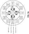
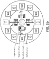
- Figures 3a-c show top-view schemes of the magneto-optical device.
- Four cuvettes containing the samples are introduced in the device. Each sample is illuminated from one side, while the optical detector is placed on the opposite side of the transparent vessel (sample). The magnetic force is perpendicular to the direction of the light propagation.
- a sigmoidal curve showing the transparency behaviour of the suspension versus the time t is obtained.
- the difference on the magnetic separation speed due the presence/absence of aggregates is determined measuring the time necessary to reach a certain level of transparency, for example the 50% between the minimal and maximal transparency.
- the time of reference is obtained using a suspension of magnetic beads without the analyte.
- the same amount of magnetic beads is added, to keep concentration constant.
- the sample is incubated and introduced in the magnetic force generator.
- the change in transparency is monitored and the time necessary to achieve the defined level of transparency determined.
- This time can be equal to the reference time: that would indicate the absence of aggregates that would not be formed if the analyte is not present in the test sample.
- the second possible outcome is that the time necessary to reach the defined level of transparency is shorter than the reference time. This second result indicates the presence of aggregates -that move faster during the separation process-, formed because the analyte is present in the tested sample.
- the experimental data can be fitted to a sigmoidal curve using the minimum squares method (or other similar algorithm). The data can then be normalized between its maximal and minimal transparency. The fitting parameters allow to get an analytical curve and determine with more precision the value of the time.
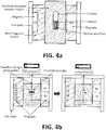
- a rectangular magnetic force generator is proposed, such that it can be incorporated into a spectrophotometer.
- Two sets of permanent magnets comprising two magnets each, is provided, which generates a homogenous magnetic force.
- the magnets have different thickness embedded in two parallel surfaces and with opposite polarities ( Figure 4a-4b ).
- the light source for this embodiment is an spectrophotometer's light source (usually UV-Visible light). Light is transmitted as before in a direction perpendicular to the magnetic force direction.
- the assembly generates a constant gradient in the sample volume (note that the required volume is relatively small) ( Figure 4a ), the same way as in the previous embodiment.
- this rectangular device allows the insertion of the sample in the working area were the magnetic field B r is higher than the saturation magnetic field B s (as shown in figure 4c )
- the use of an iron yoke (or any other soft ferromagnetic material) allows the maximization of the strength of the magnetic field gradient without increasing the size of the device, facilitating the integration within commercial spectrophotometers (as shown in figures 4a-4b ).
- 2 NdFeB magnets of 20x20x40 mm are placed over a 5 mm thick iron plate. Both magnets are magnetized along one of the shorter sides.
- the magnets are placed such that their longer sides are parallel, separated by 1 mm, aligned in its top, and with the magnetization direction pointing out of the iron plate.
- a second set of NdFeB magnets with dimensions 10x10x40 mm, are placed on a second 5 mm thick iron plate.
- the 4 magnets are magnetized along one of the 10 mm directions, and placed parallel along the 40 mm side (separated by 1 mm) and aligned in the top.
- the magnetization direction points out of the iron plate.
- the inner face of the two iron plates should be placed parallel and with the center of the magnets aligned. With this configuration, the magnetic field gradient is constant at the central area, with a value of 7 T/m.
- the value of the magnetic field is zero at 20 mm from the surface of the 10x10x40 magnets, what is 15 mm from plane equidistant to the inner faces of the iron plates.
- the field at the center is 0.113 Tesla, high enough to saturate the magnetic beads.
- the magnetic particles are functionalized with an antibody or antigen, then mixed with the sample to analyse (containing the analyte). After incubation, a shorter separation time indicates the agglutination of the magnetic particles, which can be directly or indirectly proportional to the analyte content present in the sample, depending on whether the format is Immunosandwich or competitive, respectively.
- the system could also work without the use of antibody or antigen as a molecule capture, but with the use of aptamers (both nucleotide or peptide based), with widely used biological pairs (such as streptavidin and biotin...), with molecules that present a natural capacity for binding to another molecule, and with any other alternative where there is a specific or non-specific binding between functionalized or non-functionalized particles with the analyte present in the sample.
- the method includes application to microorganisms and bacteria by mixing functionalized magnetic particles that recognize the microorganism in the sample to analyse.
- the magnetic particles can be functionalized with antibodies (or any molecule capable of recognizing and binding specifically to certain molecules exposed in the microorganism of interest).
- microorganisms-magnetic particle aggregates are formed and monitored by the magneto-optical system. Moreover, the separated microorganism-aggregates can be collected for their incubation and subsequent analyses.
- two populations of magnetic particles are each functionalized with complementary or non-complementary oligonucleotides and mixed with the sample to analyse, which might contain a complementary oligonucleotide to the one or both coated onto the magnetic particles.
- This sample might be the product of a PCR nucleotide amplification (DNA), the result of the DNA or RNA extraction of a particular cell or microorganism, or any other source of DNA or RNA.
- the separation time is shorter than the separation time of the magnetic particles, this indicates the formation of agglomerates, and then the hybridization of the oligonucleotides from both particles, indicating that the sample does not contain the complementary oligonucleotide.
- the aggregation of the particles could be due to hybridization or bridging between the DNA/RNA present in the sample and the oligonucleotides conjugated to the particles.
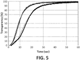
- Figure 5 shows the data of the transparency versus time during the magnetic separation for two suspensions with a concentration of 0,1% w/v.
- the particles have 230 nm of diameter and 60% of magnetite content, and the separation process was done using a cylindrical magnetic force generator with a radial gradient of 14 T/m.
- the transparency is measured by illuminating the sample with white LEDs and placing a LDR at the opposite side.
- the sample, LEDs, and detector are aligned and perpendicular to the radius of the cylinder defined by the magnetic force generator.
- the filled symbols are the transparency versus time data obtained for a magnetic bead functionalized with anti-C-Reactive Protein, (CRP) antibodies suspension incubated with a sample without CRP.
- CRP C-Reactive Protein
- the filled symbols curve corresponds to the suspension incubated with a sample without CRP.
- the open symbols curve corresponds to the suspension incubated with a sample with CRP.
- the t 50 value for the sample without the presence of CRP is 14.5 seconds.
- the open symbol curve has a t 50 of 8.7 seconds, shorter than the reference value of 14.5 seconds, thus indicating the presence of magnetic beads aggregates due the presence of CRP in the sample.
- the method can be applied for detection of proteins, small molecules, microorganisms and DNA between others.
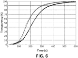
- Figure 6 shows the transparency versus time data during the magnetic separation of magnetic particles (240nm of diameter and 40% of ferrite content), using the device described in figures 4a-4b .
- the described device generates a magnetic field gradient of 7 T/m.
- Two suspensions of magnetic particles (0.001% w/v) were prepared and the magnetic separation process was performed in a commercial spectrophotometer at 350 nm wavelength.
- DNA sequence of interest is not present (filled symbols).
- the DNA sequence of interest is present.
- the magnetic particles in the suspension absorb the incident light and then the light is partially transmitted to the detector (the spectrophotometer detector). As the magnetic particles start moving to the wall under the applied magnetic force, more light is transmitted to the detector. At the end of the process, the transmittance reaches it maximum indicating the end of the process.
- the obtained t 50 is 219 seconds.
- the open symbol graph we obtain a t 50 of 176 seconds, indicating the presence of aggregates caused by the presence of the DNA sequence.
- the separation times are longer because of the lower concentration of the magnetic particles in the suspensions. The separation times can be shortened by using magnetic force generators with higher magnetic gradients.
Landscapes
- Immunology (AREA)
- Physics & Mathematics (AREA)
- Health & Medical Sciences (AREA)
- Chemical & Material Sciences (AREA)
- General Physics & Mathematics (AREA)
- Analytical Chemistry (AREA)
- Biochemistry (AREA)
- General Health & Medical Sciences (AREA)
- Life Sciences & Earth Sciences (AREA)
- Pathology (AREA)
- Fluid Mechanics (AREA)
- Engineering & Computer Science (AREA)
- Chemical Kinetics & Catalysis (AREA)
- Plasma & Fusion (AREA)
- Dispersion Chemistry (AREA)
- Investigating Or Analysing Materials By Optical Means (AREA)
Applications Claiming Priority (1)
| Application Number | Priority Date | Filing Date | Title |
|---|---|---|---|
| PCT/ES2018/070392 WO2019229276A1 (fr) | 2018-05-30 | 2018-05-30 | Procédé optomagnétophorétique pour la détection de substances biologiques et chimiques |
Publications (2)
| Publication Number | Publication Date |
|---|---|
| EP3611491A1 true EP3611491A1 (fr) | 2020-02-19 |
| EP3611491B1 EP3611491B1 (fr) | 2020-07-22 |
Family
ID=63407238
Family Applications (1)
| Application Number | Title | Priority Date | Filing Date |
|---|---|---|---|
| EP18762119.8A Active EP3611491B1 (fr) | 2018-05-30 | 2018-05-30 | Procédé optomagnétophorétique pour la détection de substances biologiques et chimiques |
Country Status (6)
| Country | Link |
|---|---|
| US (1) | US11698381B2 (fr) |
| EP (1) | EP3611491B1 (fr) |
| JP (1) | JP7264998B2 (fr) |
| CN (1) | CN110832301B (fr) |
| ES (1) | ES2827176T3 (fr) |
| WO (1) | WO2019229276A1 (fr) |
Cited By (1)
| Publication number | Priority date | Publication date | Assignee | Title |
|---|---|---|---|---|
| FR3120127A1 (fr) * | 2021-02-24 | 2022-08-26 | Magia Diagnostics | Procede et dispositif d’analyse d’un liquide susceptible de contenir un analyte |
Families Citing this family (4)
| Publication number | Priority date | Publication date | Assignee | Title |
|---|---|---|---|---|
| US20200085340A1 (en) * | 2018-09-18 | 2020-03-19 | Case Western Reserve University | Magneto-optical detection of a disease component using magnetic nanoparticles |
| CN112653249B (zh) * | 2019-10-10 | 2023-06-06 | 北京小米移动软件有限公司 | 无线充电系统,充电区域的确定方法及装置、电子设备 |
| WO2022234680A1 (fr) * | 2021-05-07 | 2022-11-10 | 大平研究所株式会社 | Procédé et système de mesure de liquide de dispersion à fines bulles |
| CN115235958B (zh) * | 2022-07-22 | 2024-04-23 | 中南大学 | 基于光学磁驱相差检测的磁性纳米颗粒粒径分析系统 |
Family Cites Families (21)
| Publication number | Priority date | Publication date | Assignee | Title |
|---|---|---|---|---|
| EP0339623B1 (fr) | 1988-04-26 | 1993-12-15 | Nippon Telegraph And Telephone Corporation | Méthode d'essai immunologique laser-magnétique et appareil à cet effet |
| JP2002357594A (ja) | 2001-03-28 | 2002-12-13 | Olympus Optical Co Ltd | 磁気粒子識別装置及び磁気粒子識別方法 |
| FR2832507B1 (fr) * | 2001-11-20 | 2004-02-20 | Stago Diagnostica | Methode de detection d'analyte(s) a l'aide de particules magnetiques colloidales |
| CN1184482C (zh) * | 2002-12-30 | 2005-01-12 | 上海交通大学 | 磁分离型免疫反应光学检测装置及其检测方法 |
| ATE543428T1 (de) | 2003-04-15 | 2012-02-15 | Koninkl Philips Electronics Nv | Anordnung sowie verfahren zur räumlich aufgelösten bestimmung von zustandsgrössen in einem untersuchungsbereich |
| EP2092339B1 (fr) * | 2006-12-12 | 2012-05-16 | Koninklijke Philips Electronics N.V. | Capteur microélectronique pour détecter des particules de marquage |
| US8821799B2 (en) * | 2007-01-26 | 2014-09-02 | Palo Alto Research Center Incorporated | Method and system implementing spatially modulated excitation or emission for particle characterization with enhanced sensitivity |
| JP5393652B2 (ja) * | 2007-03-23 | 2014-01-22 | ビーエーエスエフ ソシエタス・ヨーロピア | 表面改質ナノ粒状金属酸化物、金属水酸化物および/または金属酸化水酸化物の製造法 |
| US20100129260A1 (en) * | 2007-05-01 | 2010-05-27 | Yoshiaki Shirasawa | Gelation measuring apparatus and sample cell |
| JP5214982B2 (ja) | 2008-01-16 | 2013-06-19 | オーソ・クリニカル・ダイアグノスティックス株式会社 | 検査装置 |
| CN101497036B (zh) * | 2008-02-03 | 2011-12-07 | 陆晓唯 | 利用光的干涉法提高纳米薄膜光催化功能的方法 |
| US8324833B2 (en) * | 2008-02-06 | 2012-12-04 | Nxp B.V. | Light color tunability |
| US8822227B2 (en) * | 2008-02-06 | 2014-09-02 | Koninklijke Philips N.V. | Magnetic bead actuation using feedback for FTIR biosensor |
| EP2108938A1 (fr) * | 2008-04-09 | 2009-10-14 | Koninklijke Philips Electronics N.V. | Support de détection optique dans de petits volumes d'échantillons |
| US9557326B2 (en) * | 2010-06-09 | 2017-01-31 | Hitachi High-Technologies Corporation | Sample analyzing device and sample analyzing method |
| FR2986617B1 (fr) | 2012-02-02 | 2015-03-27 | Horiba Abx Sas | Dispositif et procede pour effectuer des mesures hematologiques et biochimiques a partir d'un echantillon biologique |
| JP6207933B2 (ja) * | 2012-08-31 | 2017-10-04 | 東芝メディカルシステムズ株式会社 | 検体検査装置 |
| AU2014301652B2 (en) * | 2013-06-28 | 2018-04-19 | Cic Nanogune | Biosensor based on measurements of the clustering dynamics of magnetic particles |
| JP6466775B2 (ja) * | 2015-04-30 | 2019-02-06 | シスメックス株式会社 | 検体分析カートリッジを用いた検体分析方法、検体分析カートリッジ、および、検体分析装置 |
| CN104949904B (zh) * | 2015-06-29 | 2017-10-27 | 广州机械科学研究院有限公司 | 一种检测流体磁性颗粒的装置与方法 |
| WO2017053630A1 (fr) * | 2015-09-22 | 2017-03-30 | Purdue Research Foundation | Isolement et détection de cellules rares sans force centrifuge |
-
2018
- 2018-05-30 CN CN201880038673.2A patent/CN110832301B/zh active Active
- 2018-05-30 EP EP18762119.8A patent/EP3611491B1/fr active Active
- 2018-05-30 US US16/613,401 patent/US11698381B2/en active Active
- 2018-05-30 WO PCT/ES2018/070392 patent/WO2019229276A1/fr not_active Ceased
- 2018-05-30 ES ES18762119T patent/ES2827176T3/es active Active
- 2018-05-30 JP JP2021517532A patent/JP7264998B2/ja active Active
Cited By (2)
| Publication number | Priority date | Publication date | Assignee | Title |
|---|---|---|---|---|
| FR3120127A1 (fr) * | 2021-02-24 | 2022-08-26 | Magia Diagnostics | Procede et dispositif d’analyse d’un liquide susceptible de contenir un analyte |
| WO2022180334A1 (fr) * | 2021-02-24 | 2022-09-01 | Magia Diagnostics | Procede et dispositif d'analyse d'un liquide susceptible de contenir un analyte |
Also Published As
| Publication number | Publication date |
|---|---|
| JP2022503880A (ja) | 2022-01-12 |
| EP3611491B1 (fr) | 2020-07-22 |
| CN110832301B (zh) | 2022-05-27 |
| JP7264998B2 (ja) | 2023-04-25 |
| US11698381B2 (en) | 2023-07-11 |
| CN110832301A (zh) | 2020-02-21 |
| ES2827176T3 (es) | 2021-05-20 |
| US20210333296A1 (en) | 2021-10-28 |
| WO2019229276A1 (fr) | 2019-12-05 |
Similar Documents
| Publication | Publication Date | Title |
|---|---|---|
| EP3611491B1 (fr) | Procédé optomagnétophorétique pour la détection de substances biologiques et chimiques | |
| US20230071162A1 (en) | Methods and apparatus for magnetic multi-bead assays | |
| Moser et al. | On-chip immuno-agglutination assay with analyte capture by dynamic manipulation of superparamagnetic beads | |
| JP5970153B2 (ja) | 凝集パラメータの測定 | |
| US7332353B2 (en) | Method for detecting analyte(s) using magnetic colloidal particles | |
| JP2000513437A (ja) | 外部及び内部勾配を有する磁気分離 | |
| WO2011026030A1 (fr) | Système intégré de préparation d'échantillons et de détection d'analytes | |
| WO2008156688A2 (fr) | Séparation magnétophorétique non-linéaire de substances biologiques | |
| JP2010060567A (ja) | 粒子に基づく結合アッセイ法 | |
| CN101627297B (zh) | 测量凝集参数 | |
| JP2021103183A (ja) | アナライトの検出およびそのための方法 | |
| WO2021096725A1 (fr) | Systèmes de perles, procédés, et appareil pour la détection d'analytes basée sur des perles magnétiques | |
| Kim et al. | Utilization of microparticles in next-generation assays for microflow cytometers | |
| Giacometti et al. | On‐chip magnetophoretic capture in a model of malaria‐infected red blood cells | |
| US20130078615A1 (en) | Device and Method for Detection and Quantification of Immunological Proteins, Pathogenic and Microbial Agents and Cells | |
| Bakhshayesh et al. | Magnetic-material-assisted bioassays: From millimeter magnetic bars to nanometer magnetic particles | |
| Van Ommering | Dynamics of individual magnetic particles near a biosensor surface | |
| Class et al. | Patent application title: METHOD FOR CAPTURING, METHOD FOR DETECTING AND KIT FOR CAPTURING A MOLECULE IN A SAMPLE Inventors: Guillaume Blair (Magland, FR) Luiz Fernando Zanini (Grenoble, FR) Gilbert Reyne (Marseille, FR) Nora Dempsey (Grenoble, FR) Marianne Weidenhaupt (St Joseph De Rivière, FR) Franz Bruckert (Grenoble, FR) Orphee Cugat (Poisat, FR) Assignees: Centre National De La Recherche Scientifique (CNRS) | |
| Dosev et al. | Multiplexed Immunoassays for Proteins Using Magnetic Luminescent Nanoparticles for Internal Calibration |
Legal Events
| Date | Code | Title | Description |
|---|---|---|---|
| STAA | Information on the status of an ep patent application or granted ep patent |
Free format text: STATUS: UNKNOWN |
|
| STAA | Information on the status of an ep patent application or granted ep patent |
Free format text: STATUS: THE INTERNATIONAL PUBLICATION HAS BEEN MADE |
|
| PUAI | Public reference made under article 153(3) epc to a published international application that has entered the european phase |
Free format text: ORIGINAL CODE: 0009012 |
|
| STAA | Information on the status of an ep patent application or granted ep patent |
Free format text: STATUS: REQUEST FOR EXAMINATION WAS MADE |
|
| 17P | Request for examination filed |
Effective date: 20191115 |
|
| AK | Designated contracting states |
Kind code of ref document: A1 Designated state(s): AL AT BE BG CH CY CZ DE DK EE ES FI FR GB GR HR HU IE IS IT LI LT LU LV MC MK MT NL NO PL PT RO RS SE SI SK SM TR |
|
| AX | Request for extension of the european patent |
Extension state: BA ME |
|
| GRAP | Despatch of communication of intention to grant a patent |
Free format text: ORIGINAL CODE: EPIDOSNIGR1 |
|
| STAA | Information on the status of an ep patent application or granted ep patent |
Free format text: STATUS: GRANT OF PATENT IS INTENDED |
|
| DAV | Request for validation of the european patent (deleted) | ||
| DAX | Request for extension of the european patent (deleted) | ||
| INTG | Intention to grant announced |
Effective date: 20200320 |
|
| RIN1 | Information on inventor provided before grant (corrected) |
Inventor name: GASSO PONS, SERGI Inventor name: BENELMEKKI ERRETBY, MARIA Inventor name: MARTINEZ GARCIA, LLUIS MIQUEL |
|
| GRAS | Grant fee paid |
Free format text: ORIGINAL CODE: EPIDOSNIGR3 |
|
| GRAA | (expected) grant |
Free format text: ORIGINAL CODE: 0009210 |
|
| STAA | Information on the status of an ep patent application or granted ep patent |
Free format text: STATUS: THE PATENT HAS BEEN GRANTED |
|
| AK | Designated contracting states |
Kind code of ref document: B1 Designated state(s): AL AT BE BG CH CY CZ DE DK EE ES FI FR GB GR HR HU IE IS IT LI LT LU LV MC MK MT NL NO PL PT RO RS SE SI SK SM TR |
|
| REG | Reference to a national code |
Ref country code: GB Ref legal event code: FG4D |
|
| REG | Reference to a national code |
Ref country code: CH Ref legal event code: EP |
|
| REG | Reference to a national code |
Ref country code: DE Ref legal event code: R096 Ref document number: 602018006287 Country of ref document: DE |
|
| REG | Reference to a national code |
Ref country code: AT Ref legal event code: REF Ref document number: 1293861 Country of ref document: AT Kind code of ref document: T Effective date: 20200815 |
|
| REG | Reference to a national code |
Ref country code: IE Ref legal event code: FG4D |
|
| REG | Reference to a national code |
Ref country code: CH Ref legal event code: NV Representative=s name: CABINET GERMAIN AND MAUREAU, CH |
|
| REG | Reference to a national code |
Ref country code: LT Ref legal event code: MG4D |
|
| REG | Reference to a national code |
Ref country code: AT Ref legal event code: MK05 Ref document number: 1293861 Country of ref document: AT Kind code of ref document: T Effective date: 20200722 |
|
| PG25 | Lapsed in a contracting state [announced via postgrant information from national office to epo] |
Ref country code: NO Free format text: LAPSE BECAUSE OF FAILURE TO SUBMIT A TRANSLATION OF THE DESCRIPTION OR TO PAY THE FEE WITHIN THE PRESCRIBED TIME-LIMIT Effective date: 20201022 Ref country code: BG Free format text: LAPSE BECAUSE OF FAILURE TO SUBMIT A TRANSLATION OF THE DESCRIPTION OR TO PAY THE FEE WITHIN THE PRESCRIBED TIME-LIMIT Effective date: 20201022 Ref country code: GR Free format text: LAPSE BECAUSE OF FAILURE TO SUBMIT A TRANSLATION OF THE DESCRIPTION OR TO PAY THE FEE WITHIN THE PRESCRIBED TIME-LIMIT Effective date: 20201023 Ref country code: LT Free format text: LAPSE BECAUSE OF FAILURE TO SUBMIT A TRANSLATION OF THE DESCRIPTION OR TO PAY THE FEE WITHIN THE PRESCRIBED TIME-LIMIT Effective date: 20200722 Ref country code: PT Free format text: LAPSE BECAUSE OF FAILURE TO SUBMIT A TRANSLATION OF THE DESCRIPTION OR TO PAY THE FEE WITHIN THE PRESCRIBED TIME-LIMIT Effective date: 20201123 Ref country code: AT Free format text: LAPSE BECAUSE OF FAILURE TO SUBMIT A TRANSLATION OF THE DESCRIPTION OR TO PAY THE FEE WITHIN THE PRESCRIBED TIME-LIMIT Effective date: 20200722 Ref country code: FI Free format text: LAPSE BECAUSE OF FAILURE TO SUBMIT A TRANSLATION OF THE DESCRIPTION OR TO PAY THE FEE WITHIN THE PRESCRIBED TIME-LIMIT Effective date: 20200722 Ref country code: HR Free format text: LAPSE BECAUSE OF FAILURE TO SUBMIT A TRANSLATION OF THE DESCRIPTION OR TO PAY THE FEE WITHIN THE PRESCRIBED TIME-LIMIT Effective date: 20200722 Ref country code: SE Free format text: LAPSE BECAUSE OF FAILURE TO SUBMIT A TRANSLATION OF THE DESCRIPTION OR TO PAY THE FEE WITHIN THE PRESCRIBED TIME-LIMIT Effective date: 20200722 |
|
| PG25 | Lapsed in a contracting state [announced via postgrant information from national office to epo] |
Ref country code: RS Free format text: LAPSE BECAUSE OF FAILURE TO SUBMIT A TRANSLATION OF THE DESCRIPTION OR TO PAY THE FEE WITHIN THE PRESCRIBED TIME-LIMIT Effective date: 20200722 Ref country code: LV Free format text: LAPSE BECAUSE OF FAILURE TO SUBMIT A TRANSLATION OF THE DESCRIPTION OR TO PAY THE FEE WITHIN THE PRESCRIBED TIME-LIMIT Effective date: 20200722 Ref country code: PL Free format text: LAPSE BECAUSE OF FAILURE TO SUBMIT A TRANSLATION OF THE DESCRIPTION OR TO PAY THE FEE WITHIN THE PRESCRIBED TIME-LIMIT Effective date: 20200722 Ref country code: IS Free format text: LAPSE BECAUSE OF FAILURE TO SUBMIT A TRANSLATION OF THE DESCRIPTION OR TO PAY THE FEE WITHIN THE PRESCRIBED TIME-LIMIT Effective date: 20201122 |
|
| PG25 | Lapsed in a contracting state [announced via postgrant information from national office to epo] |
Ref country code: NL Free format text: LAPSE BECAUSE OF FAILURE TO SUBMIT A TRANSLATION OF THE DESCRIPTION OR TO PAY THE FEE WITHIN THE PRESCRIBED TIME-LIMIT Effective date: 20200722 |
|
| REG | Reference to a national code |
Ref country code: DE Ref legal event code: R097 Ref document number: 602018006287 Country of ref document: DE |
|
| PG25 | Lapsed in a contracting state [announced via postgrant information from national office to epo] |
Ref country code: RO Free format text: LAPSE BECAUSE OF FAILURE TO SUBMIT A TRANSLATION OF THE DESCRIPTION OR TO PAY THE FEE WITHIN THE PRESCRIBED TIME-LIMIT Effective date: 20200722 Ref country code: DK Free format text: LAPSE BECAUSE OF FAILURE TO SUBMIT A TRANSLATION OF THE DESCRIPTION OR TO PAY THE FEE WITHIN THE PRESCRIBED TIME-LIMIT Effective date: 20200722 Ref country code: CZ Free format text: LAPSE BECAUSE OF FAILURE TO SUBMIT A TRANSLATION OF THE DESCRIPTION OR TO PAY THE FEE WITHIN THE PRESCRIBED TIME-LIMIT Effective date: 20200722 Ref country code: EE Free format text: LAPSE BECAUSE OF FAILURE TO SUBMIT A TRANSLATION OF THE DESCRIPTION OR TO PAY THE FEE WITHIN THE PRESCRIBED TIME-LIMIT Effective date: 20200722 Ref country code: SM Free format text: LAPSE BECAUSE OF FAILURE TO SUBMIT A TRANSLATION OF THE DESCRIPTION OR TO PAY THE FEE WITHIN THE PRESCRIBED TIME-LIMIT Effective date: 20200722 |
|
| REG | Reference to a national code |
Ref country code: ES Ref legal event code: FG2A Ref document number: 2827176 Country of ref document: ES Kind code of ref document: T3 Effective date: 20210520 |
|
| PLBE | No opposition filed within time limit |
Free format text: ORIGINAL CODE: 0009261 |
|
| STAA | Information on the status of an ep patent application or granted ep patent |
Free format text: STATUS: NO OPPOSITION FILED WITHIN TIME LIMIT |
|
| PG25 | Lapsed in a contracting state [announced via postgrant information from national office to epo] |
Ref country code: AL Free format text: LAPSE BECAUSE OF FAILURE TO SUBMIT A TRANSLATION OF THE DESCRIPTION OR TO PAY THE FEE WITHIN THE PRESCRIBED TIME-LIMIT Effective date: 20200722 |
|
| 26N | No opposition filed |
Effective date: 20210423 |
|
| PG25 | Lapsed in a contracting state [announced via postgrant information from national office to epo] |
Ref country code: SK Free format text: LAPSE BECAUSE OF FAILURE TO SUBMIT A TRANSLATION OF THE DESCRIPTION OR TO PAY THE FEE WITHIN THE PRESCRIBED TIME-LIMIT Effective date: 20200722 |
|
| REG | Reference to a national code |
Ref country code: NL Ref legal event code: MP Effective date: 20200722 |
|
| PG25 | Lapsed in a contracting state [announced via postgrant information from national office to epo] |
Ref country code: LU Free format text: LAPSE BECAUSE OF NON-PAYMENT OF DUE FEES Effective date: 20210530 Ref country code: MC Free format text: LAPSE BECAUSE OF FAILURE TO SUBMIT A TRANSLATION OF THE DESCRIPTION OR TO PAY THE FEE WITHIN THE PRESCRIBED TIME-LIMIT Effective date: 20200722 |
|
| REG | Reference to a national code |
Ref country code: BE Ref legal event code: MM Effective date: 20210531 |
|
| PG25 | Lapsed in a contracting state [announced via postgrant information from national office to epo] |
Ref country code: IE Free format text: LAPSE BECAUSE OF NON-PAYMENT OF DUE FEES Effective date: 20210530 |
|
| PG25 | Lapsed in a contracting state [announced via postgrant information from national office to epo] |
Ref country code: BE Free format text: LAPSE BECAUSE OF NON-PAYMENT OF DUE FEES Effective date: 20210531 |
|
| P01 | Opt-out of the competence of the unified patent court (upc) registered |
Effective date: 20230421 |
|
| PG25 | Lapsed in a contracting state [announced via postgrant information from national office to epo] |
Ref country code: CY Free format text: LAPSE BECAUSE OF FAILURE TO SUBMIT A TRANSLATION OF THE DESCRIPTION OR TO PAY THE FEE WITHIN THE PRESCRIBED TIME-LIMIT Effective date: 20200722 |
|
| PG25 | Lapsed in a contracting state [announced via postgrant information from national office to epo] |
Ref country code: HU Free format text: LAPSE BECAUSE OF FAILURE TO SUBMIT A TRANSLATION OF THE DESCRIPTION OR TO PAY THE FEE WITHIN THE PRESCRIBED TIME-LIMIT; INVALID AB INITIO Effective date: 20180530 |
|
| PG25 | Lapsed in a contracting state [announced via postgrant information from national office to epo] |
Ref country code: SI Free format text: LAPSE BECAUSE OF FAILURE TO SUBMIT A TRANSLATION OF THE DESCRIPTION OR TO PAY THE FEE WITHIN THE PRESCRIBED TIME-LIMIT Effective date: 20200722 |
|
| REG | Reference to a national code |
Ref country code: DE Ref legal event code: R082 Ref document number: 602018006287 Country of ref document: DE Representative=s name: KRAUS & LEDERER PARTGMBB, DE |
|
| PG25 | Lapsed in a contracting state [announced via postgrant information from national office to epo] |
Ref country code: MK Free format text: LAPSE BECAUSE OF FAILURE TO SUBMIT A TRANSLATION OF THE DESCRIPTION OR TO PAY THE FEE WITHIN THE PRESCRIBED TIME-LIMIT Effective date: 20200722 |
|
| PG25 | Lapsed in a contracting state [announced via postgrant information from national office to epo] |
Ref country code: TR Free format text: LAPSE BECAUSE OF FAILURE TO SUBMIT A TRANSLATION OF THE DESCRIPTION OR TO PAY THE FEE WITHIN THE PRESCRIBED TIME-LIMIT Effective date: 20200722 |
|
| PG25 | Lapsed in a contracting state [announced via postgrant information from national office to epo] |
Ref country code: MT Free format text: LAPSE BECAUSE OF FAILURE TO SUBMIT A TRANSLATION OF THE DESCRIPTION OR TO PAY THE FEE WITHIN THE PRESCRIBED TIME-LIMIT Effective date: 20200722 |
|
| REG | Reference to a national code |
Ref country code: ES Ref legal event code: PC2A Owner name: SEPMAG SYSTEMS, S.L. Effective date: 20250307 |
|
| PGFP | Annual fee paid to national office [announced via postgrant information from national office to epo] |
Ref country code: DE Payment date: 20250520 Year of fee payment: 8 |
|
| PGFP | Annual fee paid to national office [announced via postgrant information from national office to epo] |
Ref country code: ES Payment date: 20250603 Year of fee payment: 8 |
|
| PGFP | Annual fee paid to national office [announced via postgrant information from national office to epo] |
Ref country code: IT Payment date: 20250527 Year of fee payment: 8 |
|
| PGFP | Annual fee paid to national office [announced via postgrant information from national office to epo] |
Ref country code: FR Payment date: 20250411 Year of fee payment: 8 |
|
| PGFP | Annual fee paid to national office [announced via postgrant information from national office to epo] |
Ref country code: CH Payment date: 20250601 Year of fee payment: 8 |
|
| REG | Reference to a national code |
Ref country code: DE Ref legal event code: R081 Ref document number: 602018006287 Country of ref document: DE Owner name: SEPMAG SYSTEMS, S.L., CERDANYOLA DEL VALLES, ES Free format text: FORMER OWNERS: PRAGMATIC DIAGNOSTICS, S.L., SANT PRIVAT D'EN BAS, GIRONA, ES; SEPMAG SYSTEMS, S.L., CERDANYOLA DEL VALLES, BARCELONA, ES |
|
| REG | Reference to a national code |
Ref country code: GB Ref legal event code: 732E Free format text: REGISTERED BETWEEN 20250731 AND 20250806 |
|
| PGFP | Annual fee paid to national office [announced via postgrant information from national office to epo] |
Ref country code: GB Payment date: 20260324 Year of fee payment: 9 |