EP3611537A2 - Radarsysteme und verfahren zum betrieb von radarsystemen - Google Patents
Radarsysteme und verfahren zum betrieb von radarsystemen Download PDFInfo
- Publication number
- EP3611537A2 EP3611537A2 EP19190585.0A EP19190585A EP3611537A2 EP 3611537 A2 EP3611537 A2 EP 3611537A2 EP 19190585 A EP19190585 A EP 19190585A EP 3611537 A2 EP3611537 A2 EP 3611537A2
- Authority
- EP
- European Patent Office
- Prior art keywords
- chirp
- chirps
- repeating pattern
- signal
- radar
- Prior art date
- Legal status (The legal status is an assumption and is not a legal conclusion. Google has not performed a legal analysis and makes no representation as to the accuracy of the status listed.)
- Ceased
Links
- 238000000034 method Methods 0.000 title claims abstract description 36
- 238000004891 communication Methods 0.000 description 8
- 230000000116 mitigating effect Effects 0.000 description 7
- 238000001514 detection method Methods 0.000 description 4
- 230000003287 optical effect Effects 0.000 description 3
- 235000008694 Humulus lupulus Nutrition 0.000 description 2
- 239000013078 crystal Substances 0.000 description 2
- 238000010586 diagram Methods 0.000 description 2
- 230000006870 function Effects 0.000 description 2
- 230000002452 interceptive effect Effects 0.000 description 2
- 230000002093 peripheral effect Effects 0.000 description 2
- 230000010287 polarization Effects 0.000 description 2
- 239000004065 semiconductor Substances 0.000 description 2
- 230000004075 alteration Effects 0.000 description 1
- 230000005540 biological transmission Effects 0.000 description 1
- 238000006243 chemical reaction Methods 0.000 description 1
- 230000001427 coherent effect Effects 0.000 description 1
- 238000004590 computer program Methods 0.000 description 1
- 238000010295 mobile communication Methods 0.000 description 1
- 230000003252 repetitive effect Effects 0.000 description 1
- 230000011664 signaling Effects 0.000 description 1
- 239000007787 solid Substances 0.000 description 1
- 238000001228 spectrum Methods 0.000 description 1
- 230000001360 synchronised effect Effects 0.000 description 1
Images


Classifications
-
- G—PHYSICS
- G01—MEASURING; TESTING
- G01S—RADIO DIRECTION-FINDING; RADIO NAVIGATION; DETERMINING DISTANCE OR VELOCITY BY USE OF RADIO WAVES; LOCATING OR PRESENCE-DETECTING BY USE OF THE REFLECTION OR RERADIATION OF RADIO WAVES; ANALOGOUS ARRANGEMENTS USING OTHER WAVES
- G01S13/00—Systems using the reflection or reradiation of radio waves, e.g. radar systems; Analogous systems using reflection or reradiation of waves whose nature or wavelength is irrelevant or unspecified
- G01S13/02—Systems using reflection of radio waves, e.g. primary radar systems; Analogous systems
- G01S13/06—Systems determining position data of a target
- G01S13/08—Systems for measuring distance only
- G01S13/32—Systems for measuring distance only using transmission of continuous waves, whether amplitude-, frequency-, or phase-modulated, or unmodulated
- G01S13/34—Systems for measuring distance only using transmission of continuous waves, whether amplitude-, frequency-, or phase-modulated, or unmodulated using transmission of continuous, frequency-modulated waves while heterodyning the received signal, or a signal derived therefrom, with a locally-generated signal related to the contemporaneously transmitted signal
- G01S13/343—Systems for measuring distance only using transmission of continuous waves, whether amplitude-, frequency-, or phase-modulated, or unmodulated using transmission of continuous, frequency-modulated waves while heterodyning the received signal, or a signal derived therefrom, with a locally-generated signal related to the contemporaneously transmitted signal using sawtooth modulation
-
- G—PHYSICS
- G01—MEASURING; TESTING
- G01S—RADIO DIRECTION-FINDING; RADIO NAVIGATION; DETERMINING DISTANCE OR VELOCITY BY USE OF RADIO WAVES; LOCATING OR PRESENCE-DETECTING BY USE OF THE REFLECTION OR RERADIATION OF RADIO WAVES; ANALOGOUS ARRANGEMENTS USING OTHER WAVES
- G01S7/00—Details of systems according to groups G01S13/00, G01S15/00, G01S17/00
- G01S7/02—Details of systems according to groups G01S13/00, G01S15/00, G01S17/00 of systems according to group G01S13/00
- G01S7/023—Interference mitigation, e.g. reducing or avoiding non-intentional interference with other HF-transmitters, base station transmitters for mobile communication or other radar systems, e.g. using electro-magnetic interference [EMI] reduction techniques
-
- G—PHYSICS
- G01—MEASURING; TESTING
- G01S—RADIO DIRECTION-FINDING; RADIO NAVIGATION; DETERMINING DISTANCE OR VELOCITY BY USE OF RADIO WAVES; LOCATING OR PRESENCE-DETECTING BY USE OF THE REFLECTION OR RERADIATION OF RADIO WAVES; ANALOGOUS ARRANGEMENTS USING OTHER WAVES
- G01S13/00—Systems using the reflection or reradiation of radio waves, e.g. radar systems; Analogous systems using reflection or reradiation of waves whose nature or wavelength is irrelevant or unspecified
- G01S13/02—Systems using reflection of radio waves, e.g. primary radar systems; Analogous systems
- G01S13/50—Systems of measurement based on relative movement of target
- G01S13/58—Velocity or trajectory determination systems; Sense-of-movement determination systems
- G01S13/583—Velocity or trajectory determination systems; Sense-of-movement determination systems using transmission of continuous unmodulated waves, amplitude-, frequency-, or phase-modulated waves and based upon the Doppler effect resulting from movement of targets
- G01S13/584—Velocity or trajectory determination systems; Sense-of-movement determination systems using transmission of continuous unmodulated waves, amplitude-, frequency-, or phase-modulated waves and based upon the Doppler effect resulting from movement of targets adapted for simultaneous range and velocity measurements
-
- G—PHYSICS
- G01—MEASURING; TESTING
- G01S—RADIO DIRECTION-FINDING; RADIO NAVIGATION; DETERMINING DISTANCE OR VELOCITY BY USE OF RADIO WAVES; LOCATING OR PRESENCE-DETECTING BY USE OF THE REFLECTION OR RERADIATION OF RADIO WAVES; ANALOGOUS ARRANGEMENTS USING OTHER WAVES
- G01S13/00—Systems using the reflection or reradiation of radio waves, e.g. radar systems; Analogous systems using reflection or reradiation of waves whose nature or wavelength is irrelevant or unspecified
- G01S13/88—Radar or analogous systems specially adapted for specific applications
- G01S13/93—Radar or analogous systems specially adapted for specific applications for anti-collision purposes
- G01S13/931—Radar or analogous systems specially adapted for specific applications for anti-collision purposes of land vehicles
-
- G—PHYSICS
- G01—MEASURING; TESTING
- G01S—RADIO DIRECTION-FINDING; RADIO NAVIGATION; DETERMINING DISTANCE OR VELOCITY BY USE OF RADIO WAVES; LOCATING OR PRESENCE-DETECTING BY USE OF THE REFLECTION OR RERADIATION OF RADIO WAVES; ANALOGOUS ARRANGEMENTS USING OTHER WAVES
- G01S7/00—Details of systems according to groups G01S13/00, G01S15/00, G01S17/00
- G01S7/02—Details of systems according to groups G01S13/00, G01S15/00, G01S17/00 of systems according to group G01S13/00
- G01S7/023—Interference mitigation, e.g. reducing or avoiding non-intentional interference with other HF-transmitters, base station transmitters for mobile communication or other radar systems, e.g. using electro-magnetic interference [EMI] reduction techniques
- G01S7/0232—Avoidance by frequency multiplex
-
- G—PHYSICS
- G01—MEASURING; TESTING
- G01S—RADIO DIRECTION-FINDING; RADIO NAVIGATION; DETERMINING DISTANCE OR VELOCITY BY USE OF RADIO WAVES; LOCATING OR PRESENCE-DETECTING BY USE OF THE REFLECTION OR RERADIATION OF RADIO WAVES; ANALOGOUS ARRANGEMENTS USING OTHER WAVES
- G01S7/00—Details of systems according to groups G01S13/00, G01S15/00, G01S17/00
- G01S7/02—Details of systems according to groups G01S13/00, G01S15/00, G01S17/00 of systems according to group G01S13/00
- G01S7/023—Interference mitigation, e.g. reducing or avoiding non-intentional interference with other HF-transmitters, base station transmitters for mobile communication or other radar systems, e.g. using electro-magnetic interference [EMI] reduction techniques
- G01S7/0234—Avoidance by code multiplex
-
- G—PHYSICS
- G01—MEASURING; TESTING
- G01S—RADIO DIRECTION-FINDING; RADIO NAVIGATION; DETERMINING DISTANCE OR VELOCITY BY USE OF RADIO WAVES; LOCATING OR PRESENCE-DETECTING BY USE OF THE REFLECTION OR RERADIATION OF RADIO WAVES; ANALOGOUS ARRANGEMENTS USING OTHER WAVES
- G01S7/00—Details of systems according to groups G01S13/00, G01S15/00, G01S17/00
- G01S7/02—Details of systems according to groups G01S13/00, G01S15/00, G01S17/00 of systems according to group G01S13/00
- G01S7/35—Details of non-pulse systems
- G01S7/352—Receivers
-
- G—PHYSICS
- G01—MEASURING; TESTING
- G01S—RADIO DIRECTION-FINDING; RADIO NAVIGATION; DETERMINING DISTANCE OR VELOCITY BY USE OF RADIO WAVES; LOCATING OR PRESENCE-DETECTING BY USE OF THE REFLECTION OR RERADIATION OF RADIO WAVES; ANALOGOUS ARRANGEMENTS USING OTHER WAVES
- G01S7/00—Details of systems according to groups G01S13/00, G01S15/00, G01S17/00
- G01S7/02—Details of systems according to groups G01S13/00, G01S15/00, G01S17/00 of systems according to group G01S13/00
- G01S7/40—Means for monitoring or calibrating
- G01S7/4052—Means for monitoring or calibrating by simulation of echoes
- G01S7/4056—Means for monitoring or calibrating by simulation of echoes specially adapted to FMCW
-
- G—PHYSICS
- G01—MEASURING; TESTING
- G01S—RADIO DIRECTION-FINDING; RADIO NAVIGATION; DETERMINING DISTANCE OR VELOCITY BY USE OF RADIO WAVES; LOCATING OR PRESENCE-DETECTING BY USE OF THE REFLECTION OR RERADIATION OF RADIO WAVES; ANALOGOUS ARRANGEMENTS USING OTHER WAVES
- G01S7/00—Details of systems according to groups G01S13/00, G01S15/00, G01S17/00
- G01S7/02—Details of systems according to groups G01S13/00, G01S15/00, G01S17/00 of systems according to group G01S13/00
- G01S7/41—Details of systems according to groups G01S13/00, G01S15/00, G01S17/00 of systems according to group G01S13/00 using analysis of echo signal for target characterisation; Target signature; Target cross-section
- G01S7/414—Discriminating targets with respect to background clutter
-
- G—PHYSICS
- G01—MEASURING; TESTING
- G01S—RADIO DIRECTION-FINDING; RADIO NAVIGATION; DETERMINING DISTANCE OR VELOCITY BY USE OF RADIO WAVES; LOCATING OR PRESENCE-DETECTING BY USE OF THE REFLECTION OR RERADIATION OF RADIO WAVES; ANALOGOUS ARRANGEMENTS USING OTHER WAVES
- G01S7/00—Details of systems according to groups G01S13/00, G01S15/00, G01S17/00
- G01S7/003—Transmission of data between radar, sonar or lidar systems and remote stations
-
- G—PHYSICS
- G01—MEASURING; TESTING
- G01S—RADIO DIRECTION-FINDING; RADIO NAVIGATION; DETERMINING DISTANCE OR VELOCITY BY USE OF RADIO WAVES; LOCATING OR PRESENCE-DETECTING BY USE OF THE REFLECTION OR RERADIATION OF RADIO WAVES; ANALOGOUS ARRANGEMENTS USING OTHER WAVES
- G01S7/00—Details of systems according to groups G01S13/00, G01S15/00, G01S17/00
- G01S7/02—Details of systems according to groups G01S13/00, G01S15/00, G01S17/00 of systems according to group G01S13/00
- G01S7/40—Means for monitoring or calibrating
- G01S7/4052—Means for monitoring or calibrating by simulation of echoes
- G01S7/406—Means for monitoring or calibrating by simulation of echoes using internally generated reference signals, e.g. via delay line, via RF or IF signal injection or via integrated reference reflector or transponder
- G01S7/4065—Means for monitoring or calibrating by simulation of echoes using internally generated reference signals, e.g. via delay line, via RF or IF signal injection or via integrated reference reflector or transponder involving a delay line
Definitions
- Sensor systems that utilize radar are increasing being deployed in vehicles (e.g., automobiles) to implement, for example, safety and/or autonomous driving features.
- a radar system transmits radio waves and receives a reflected portion of the radio waves and then uses the round trip delay to detect the presence of an object.
- radar works well to detect the presence of objects, radar systems are subject to interference that can degrade the accuracy of object detection. For example, when a large number of vehicles that are using radar systems are located near each other, the radar signals from the different vehicles may interfere with each other and the detection of objects can become unreliable.
- radar systems are employed to implement safety and/or autonomous driving features, the reliability of radar systems is of utmost importance.
- Embodiments of a method and a device are disclosed.
- a method for operating a radar system involves generating a chirp signal having a repeating pattern of chirps, each chirp in the repeating pattern of chirps having a base frequency, a chirp bandwidth, and a chirp duration, wherein the repeating pattern of chirps includes at least two chirps that differ from each other in at least one of base frequency, chirp bandwidth, and chirp duration, transmitting a radar signal according to the chirp signal, receiving radio frequency energy that includes a reflected portion of the radar signal, and selecting for processing from the received radio frequency energy a signal that matches the repeating pattern of chirps of the chirp signal.
- the repeating pattern of chirps comprises a fixed number of chirps in each repeating pattern.
- the repeating pattern of chirps includes at least two chirps that have different base frequencies.
- the repeating pattern of chirps includes at least two chirps that have different chirp bandwidths.
- the repeating pattern of chirps includes at least two chirps that have different base frequencies and at least two chirps that have different chirp bandwidths.
- the repeating pattern of chirps comprises a fixed number of chirps in each repeating pattern and wherein the repeating pattern of chirps includes at least two chirps that have different base frequencies and at least two chirps that have different chirp bandwidths.
- generating the chirp signal involves accessing a chirp code stored in the radar system, wherein the chirp code defines the pattern of chirps.
- a radar system includes a waveform generator configured to generate a chirp signal having a repeating pattern of chirps, each chirp in the repeating pattern of chirps having a base frequency, a chirp bandwidth, and a chirp duration, wherein the repeating pattern of chirps includes at least two chirps that differ from each other in at least one of base frequency, chirp bandwidth, and chirp duration, transmitter circuitry configured to transmit a radar signal according to the chirp signal, receiver circuitry configured to receive radio frequency energy that includes a reflected portion of the radar signal, wherein the radar system is configured to select, from the received radio frequency energy a signal that matches the repeating pattern of chirps of the chirp signal.
- the repeating pattern of chirps comprises a fixed number of chirps in each repeating pattern.
- the repeating pattern of chirps includes at least two chirps that have different base frequencies.
- the repeating pattern of chirps includes at least two chirps that have different chirp bandwidths.
- the repeating pattern of chirps includes at least two chirps that have different base frequencies and at least two chirps that have different chirp bandwidths.
- the repeating pattern of chirps comprises a fixed number of chirps in each repeating pattern and wherein the repeating pattern of chirps includes at least two chirps that have different base frequencies and at least two chirps that have different chirp bandwidths.
- generating the chirp signal involves accessing a chirp code stored in the radar system, wherein the chirp code defines the pattern of chirps.
- a packaged device for a radar system includes a waveform generator configured to generate a chirp signal having a repeating pattern of chirps, each chirp in the repeating pattern of chirps having a base frequency, a chirp bandwidth, and a chirp duration, wherein the repeating pattern of chirps includes at least two chirps that differ from each other in at least one of base frequency, chirp bandwidth, and chirp duration, transmitter circuitry configured to transmit a radar signal according to the chirp signal, and a receiver circuitry configured to receive radio frequency energy that includes a reflected portion of the radar signal.
- the packaged device includes a memory on which a chirp code is stored, wherein the chirp code defines the pattern of chirps.
- the packaged device is configured to select, from the received radio frequency energy, a signal that matches the repeating pattern of chirps of the chirp signal.
- the repeating pattern of chirps comprises a fixed number of chirps in each repeating pattern.
- the repeating pattern of chirps includes at least two chirps that have different base frequencies or at least two chirps that have different chirp bandwidths.
- the repeating pattern of chirps includes at least two chirps that have different base frequencies and at least two chirps that have different chirp bandwidths.
- Radar interference may arise from, for example: emissions from non-transmitting devices (e.g., such as high power electronics); spurious, in-band, or out-of-band emissions from incumbent users in the same or similar frequency range (e.g., mobile communications and aerospace radar); and spurious, in-band, or out-of-band emissions from different vehicle radar systems of the same or similar kind, in the same or close-by vehicles. Radio frequency energy from the same or similar type of radar systems can result in particularly harmful interference that affects the primary function of the system or its functional safety.
- radar interference mitigation techniques are important, especially in multiple-vehicle or multiple-sensors-per-vehicle situations. Interference can result in, for example, ghost targets or in real targets, which are falsely interpreted as ghost targets and neglected for the wrong reason. Real targets also can be misinterpreted in terms of, for example, their proximity, speed, and/or size.
- Interference can occur if the following conditions are simultaneously met: a) the interference signal occupies the same bandwidth; b) at the same time; c) at the same location; d) with a common interference path (either line of sight or reflection/diffraction); e) with the same polarization; f) with different, uncorrelated carrier(s); g) with different, uncorrelated modulation schemes; and h) with received interference power that is perceivable, e.g., in terms of the interference to noise (I/N) power ratio.
- I/N interference to noise
- Interference mitigation or avoidance can be implemented by influencing one or more of the above mentioned parameters.
- interfering signals are present at the same time, at the same location, and with a common interference path.
- interference mitigation or avoidance techniques typically involve manipulating the carrier frequency, the carrier polarization, and/or the modulation scheme.
- One approach to interference mitigation in vehicle radar systems utilizes random frequency hopping. According to the approach, a radar signal is distributed randomly over the entire band, then backwards convoluted to eliminate the interference. Such an approach can be considered as a special "spread spectrum" approach that is well known in the field.
- conventional systems require considerable computing power to provide an acceptable correlation between the sent and the received signal.
- interference mitigation or avoidance techniques do not rely on vehicle-to-vehicle or sensor-to-sensor communication, which would impose an additional layer of complexity and risk of failure and may require a standardized communications protocol.
- FMCW frequency-modulated continuous wave
- a (quasi-) continuous carrier frequency of for example, 77 GHz is modulated by a "fast" sequence of quick upward (or downward) frequency sweeps of around, for example, 1-2 GHz.
- the quick upward (or downward) frequency sweeps typically have a duration (in time) in the range of about 100us, in some applications the duration is in the range of 20 - 50us, and are often referred to as "chirps" or "ramps.”
- Fig. 1 depicts a continuous wave carrier that is modulated by a fast sequence of chirps, e.g., an FMCW signal.
- Fig. 1 depicts a radar transmitter 100 and time synchronized representations of the continuous wave carrier signal in a wave form 102 and the continuous wave carrier signal in a graph form 106 of frequency vs. time.
- the quick upward frequency sweeps ("chirps" or "ramps") of the FMCW signal are identifiable in both representations of the continuous wave carrier.
- Some known vehicle radar systems operate in a 77 GHz band that ranges from 76 GHz - 81 GHz, although the system described herein is not limited to such a band.
- a portion of the transmitted radar signal 106 is reflected by relatively large objects and the reflected portion of the radar signal 108 is received by an antenna system.
- the frequency difference between the transmitted and reflected chirp (caused by the flight time of the radar signal), referred to as the round-trip delay, provides information on the distance between the transmitter and the object off which the signal is reflected (i.e., the reflector).
- the relative speed between the transmitter and the reflector causes a Doppler shift that can be evaluated to obtain information on the relative speed between the transmitter and the reflector.
- Fig. 1 depicts only a small portion of an FMCW signal
- Fig. 2 depicts a larger portion of an FMCW signal 206 that includes a repeating pattern of 25 chirp frames 210, wherein each chirp frame includes the same number of chirps, e.g., 32 or 64 chirps, with each chirp having the same chirp duration.
- each chirp in the chirp frames has a base frequency of 77 GHz and a chirp bandwidth of 1 GHz.
- twenty-five chirp frames are transmitted per second (e.g., 25 frames-per-second (fps)).
- a method for operating a radar system for a vehicle to mitigate interference involves generating a chirp signal having a repeating pattern of chirps, with each chirp in the repeating pattern of chirps having a base frequency, a chirp bandwidth, and a chirp duration, wherein the repeating pattern of chirps includes at least two chirps that differ from each other in at least one of base frequency, chirp bandwidth, and chirp duration, transmitting a radar signal according to the chirp signal, receiving radio frequency energy that includes a reflected portion of the radar signal, and selecting for processing from the received radio frequency energy a signal that matches the repeating pattern of chirps of the chirp signal.
- the base frequency, chirp bandwidth, and/or chirp duration of a repeating pattern of chirps can be used to create a large enough pool of unique patterns or "fingerprints" that interference amongst nearby vehicles is highly unlikely or avoided altogether.
- other parameters such as the number of chirps in a chirp frame or the wait time between two chirps, can be used to create a large pool of unique patterns or "fingerprints.”
- the use of a large pool of unique patterns to mitigate interference from nearby vehicles does not rely on vehicle-to-vehicle communications, thus eliminating the need for additional communications equipment and/or communications protocols.
- the technique can be used in an environment that includes vehicles that are equipped with radar systems that implement the technique described herein and vehicles that are not equipped with such radar systems (e.g., including vehicles that are equipped with legacy radar systems).
- Figs. 3A - 3D depict examples of a chirp frame in which the base frequency, chirp bandwidth, and/or chirp duration of a repeating pattern of chirps is used to create a unique pattern or "fingerprint.”
- Fig. 3A depicts an example of a chirp frame 310 in a portion of an FMCW signal 306 that uses two different base frequencies to create a unique pattern or "fingerprint" of chirps.
- the chirp frame has thirty-two chirps, with thirty-one of the thirty-two chirps having a base frequency of 76 GHz and one chirp of the thirty-two chirps having a base frequency of 78 GHz.
- each chirp has the same chirp bandwidth (e.g., 2 GHz) and the base frequency is used to create the unique pattern of chirps.
- the unique pattern of chirps shown in Fig. 3A can be represented as, for example, low(1), low(2), high(3), low(4), low(5),..., low(32).
- chirps 1, 2, and 4-32 have a base frequency of 76 GHz and a chirp bandwidth of 2 GHz and chirp 3 has a base frequency of 78 GHz and a chirp bandwidth of 2 GHz.
- a chirp frame can have 2 32 (or 4.3 x 10 9 ) unique chirp patterns or fingerprints.
- the chirp frame 310 with the unique chirp pattern is repeated with a pause in between chirp frames.
- Fig. 3B depicts an example of a chirp frame 310 in a portion of an FMCW signal 306 that uses two different chirp bandwidths to create a unique pattern or "fingerprint" of chirps.
- the chirp frame has thirty-two chirps, with thirty-one of the thirty-two chirps having a chirp bandwidth of 2 GHz and one chirp of the thirty-two chirps having a chirp bandwidth of 4 GHz.
- each chirp has the same base frequency (e.g., 76 GHz) and the chirp bandwidth is used to create the unique pattern of chirps.
- Fig. 3C depicts an example of a chirp frame 310 in a portion of an FMCW signal 306 that uses two different chirp durations to create a unique pattern or "fingerprint" of chirps.
- the chirp frame has thirty-two chirps, with thirty-one of the thirty-two chirps having a first chirp duration and one chirp of the thirty-two chirps having a second chirp duration (e.g., twice as long as the first chirp duration).
- each chirp has the same base frequency (e.g., 76 GHz) and the same chirp bandwidth (e.g., 2 GHz) and the chirp duration is used to create the unique pattern of chirps.
- Fig. 3D depicts an example of a chirp frame 310 in a portion of an FMCW signal 306 that uses a combination of different base frequencies, chirp bandwidths, and chirp durations in the same chirp frame to create a unique pattern or "fingerprint" of chirps.
- Fig. 3D depicts an example of a chirp frame 310 in a portion of an FMCW signal 306 that uses a combination of different base frequencies, chirp bandwidths, and chirp durations in the same chirp frame to create a unique pattern or "fingerprint" of chirps.
- the chirp frame has thirty-two chirps, with at least one chirp having a base frequency of 78 GHz (as opposed to 76 GHz), with at least one chirp having a chirp duration different from the other chirps (e.g., one chirp having a chirp duration that is twice as long as the other chirps), and with at least one chirp having a chirp bandwidth of 4 GHz (as opposed to 2 GHz).
- a combination of three variable parameters is shown in Fig. 3D , a combination of just two of the variable parameters (e.g., base frequency/chirp bandwidth, base frequency/chirp duration, chirp bandwidth/chirp duration) is also possible.
- Figs. 3A - 3C involve a chirp frame 310 with thirty-two chirps and one variable parameter (i.e., base frequency, chirp bandwidth, and chirp duration, respectively) and Fig. 3D depicts a chirp pattern with three variables (i.e., base frequency, chirp bandwidth, and chirp duration).
- Other combinations of variable parameters e.g., base frequency, chirp bandwidth, and chirp duration
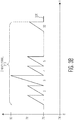
- FIGS. 4A - 4D depict four different examples of unique patterns, or fingerprints, which can be created by manipulating a combination of the number of chirps per chirp frame, the base frequency of each chirp, and the chirp bandwidth of each chirp.
- the chirps of the FMCW signal are represented as vertical lines in which the bottom end of the line corresponds to the base frequency of the chirp and the length of the vertical line corresponds to the chirp bandwidth (e.g., the increase in the chirp frequency over the duration of the chirp) over the chirp duration.
- the chirp duration is the time over which a chirp occurs (e.g., the distance on the time axis from the beginning to the end of a single chirp).
- each vertical line illustrates a chirp of the FMCW signal.
- Fig. 4A depicts a repeating pattern of N chirp frames 410-1 - 410-N, where N is an integer greater than zero.
- the chirp frames depicted in Fig. 4A include four chirps 414 of equal chirp duration per chirp frame (numbered 1 - 4), with the four chirps having four different possible base frequencies (76 GHz, 77 GHz, 78 GHz, and 79 GHz) and with each chirp having the same chirp bandwidth, 2 GHz.
- each chirp has four degrees of freedom (76 GHz, 77 GHz, 78 GHz, and 79 GHz) and there are four chirps per frame.
- a chirp frame can have 4 4 (or 256) unique chirp patterns or fingerprints.
- Fig. 4B depicts a repeating pattern of N chirp frames 410-1 - 410-N, where N is an integer greater than zero.
- the chirp frames depicted in Fig. 4B include eight chirps 414 of equal chirp duration per chirp frame (numbered 1 - 8), with the eight chirps having five different possible base frequencies (76 GHz, 77 GHz, 78 GHz, 79 GHz, and 80 GHz) and with each chirp having the same chirp bandwidth, 1 GHz.
- each chirp has five degrees of freedom (76 GHz, 77 GHz, 78 GHz, 79 GHz, and 80 GHz) and there are eight chirps per frame).
- a chirp frame can have 5 8 (or 390,625) unique chirp patterns or fingerprints.
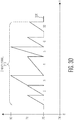
- Fig. 4C depicts a repeating pattern of N chirp frames 410-1 - 410-N, where N is an integer greater than zero.
- each chirp has two degrees of freedom (76 GHz and 78 GHz) and there are n chirps per frame).
- the base frequency and the chirp bandwidth can be varied within a single chirp frame to increase the degrees of freedom.
- Fig. 4D depicts a repeating pattern of N chirp frames 410-1 - 410-N of equal chirp duration, where N is an integer greater than zero, in which the base frequency and the chirp bandwidth are varied within a single chirp frame to increase the degrees of freedom.
- the chirp frames depicted in Fig. 4D include four chirps 414 per chirp frame (numbered 1 - 4), with the four chirps having base frequencies of 76 GHz, 78 GHz, 80 GHz, and 78 GHz and with the chirps having a chirp bandwidth of either 1 GHz or 2 GHz.
- a pattern that includes 24 chirps per frame, 5 different base frequencies, and 2 different chirp bandwidths produces a pool of (2x5) 24 (or 10 24 ) unique chirp patterns.
- the chirp duration may be varied to provide another degree of freedom. For practical purposes, such a large pool of unique chirp patterns is enough to allow each radar system to be considered "quasi-unique" without taking further measures to ensure absolute uniqueness. Larger chirp frames (e.g., more chirps per chirp frame) and the use of different alterations of base frequency and chirp bandwidth can be used to increase the number of unique chirp patterns.
- a radar system such as a radar system that is deployed in a vehicle (e.g., an automobile) to implement, for example, safety and/or autonomous driving features.
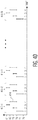
- Fig. 5 depicts an example embodiment of a radar system 500 that is configured to implement the above-described technique.
- the radar system 500 generally includes a front end 502 and a back end 504 generally demarcated by dashed line 106.
- the back end 504 includes a power management system 508, a data processor 510, which may be a microprocessor, micro controller, digital signal processor, system on chip or similar or any combination thereof, a crystal oscillator 512, and a bus or other communications interface 514 via which the processor 510 can communicate with other parts of the back end (not shown) and/or with other systems or sub-systems of a vehicle.
- interface 514 may provide an Ethernet, controller area network (CAN) or FlexRay communications interface.
- CAN controller area network
- FlexRay communications interface Various conventional parts of the radar system 500 are omitted for the sake of clarity of explanation. However, such parts will be apparent to a person of ordinary skill in the art.
- the radar system 500 is particularly suitable for automotive applications, however, the radar system can also be used in other applications.
- the front end 502 is generally an analogue front end and includes one or more radar transmitter antennas 520 and one or more radar receiver antennas 522.
- the front end 502 also includes transmitter circuitry 524, including a respective transmit path circuit, 526, for each transmitter antenna.
- the front end 502 also includes receiver circuitry 528, including a receive path circuit 530 for each respective receiver antenna 522.
- a waveform generator circuit 532 is also provided and which supplies a master local oscillator (LO) signal to each of the transmitter and receiver circuits.
- a serializer circuit 534 is also provided and includes a respective receive path serializer circuit 536 for each receive path circuit.
- a master clock generation circuit 538 is also provided and receives a signal from a crystal oscillator 512 and outputs a master clock signal to the wave form generator 532 and also to the serializer circuit 534.
- a master serial peripheral interface 540 is also provided in communication with the data processor 510, via which the data processor 510 can communicate with various parts of the analogue front end. It will be appreciated that in other embodiments, another type of control bus can be used.
- the serializer circuit 534 includes line driver circuitry via which digitized data is transmitted in low voltage differential signaling (LVDS) serial format over a pair of lines, e.g. 542, to the data processor 510. It will be appreciated that in other embodiments, other types of serial data transmission can be used.
- LVDS low voltage differential signaling
- the serializer circuit provides the general analogue to digital conversion and interface between the analogue front end and the digital data processor 510 being the digital base band.
- the serializer circuit provides the general analogue to digital conversion and interface between the analogue front end and the digital data processor 510 being the digital base band.
- the transmitter circuitry 524, the receiver circuitry 528, the waveform generator 532, the serializer circuit 534, the master clock generator 538, and the master serial peripheral interface 540 are embodied as a packaged device 550.
- the packaged device may include one or more integrated circuit (IC) devices that is/are packaged and sold as a distinct standalone packaged device that can be attached to a printed circuit board (PCB) along with other components to form a radar system.
- IC integrated circuit
- a chirp signal having a unique chirp pattern as described above is generated in the waveform generator 532.
- a radar signal is then generated by the transmitter circuit 124 according to the chirp signal and transmitted from at least one of the antenna 520.
- a stream of chirp frames, with each frame having the same pattern of chirps is transmitted from the radar system 500 as a radar signal.
- Radio frequency (RF) energy which may include a reflected portion of the transmitted radar signal, is received by the antennas 522 and processed by the receiver circuitry 528 and the serializer circuit 534.
- the serializer circuit is configured to select a signal from the received RF energy that matches the repeating pattern of chirps that was transmitted from the transmitter circuitry 524.
- the selection of the signal that matches the repeating pattern of chirps can be implemented entirely in the receiver circuitry 528 and/or the serializer circuit 534 (e.g., on the IC device 550) and in another embodiment, the selection of the signal that matches the repeating pattern of chirps can be implemented entirely in the data processor 110. In still another embodiment, the selection of the signal that matches the repeating pattern of chirps can be implemented in some combination of the receiver circuitry 528, serializer circuit 534, and/or the data processor 110.
- the repeating pattern of chirps is communicated to the receiver circuitry 528 so that the receiver circuit can filter the incoming analog signals for signals that match the transmitted chirp pattern.
- a chirp code 560 is stored in a memory 562 (e.g., a one-time programmable (OTP) memory) that is integrated into the IC device 550, where the chirp code is a digital code that indicates the specifics of the chirp pattern, e.g., how many chirps per frame, the base frequency/frequencies, chirp bandwidth(s), and chirp duration(s).
- a memory 562 e.g., a one-time programmable (OTP) memory
- OTP one-time programmable
- the receiver circuitry uses the chirp code to program an analog filter that is used to at least partially select a signal that matches the repeating pattern of chirps.
- the radar system is coherent (e.g., same pattern at the input of the transmitter and receiver) and the received signal is downconverted with knowledge of the chirp code.
- at least a portion of the selection of a signal that matches the repeating pattern of chirps is done in software in the data processor 110 using the chirp code.
- chirp codes for multiple different chirp patterns may be stored on OTP memory. In an embodiment, it is desirable to store the chirp code on the IC device so that the security of the chirp code can be ensured.
- multiple different chirp codes are stored on the same IC device and a command is sent to the IC device to select or "activate" a particular chirp code.
- the chirp codes are stored on the IC device, it is possible that the chirp code is stored "off-chip” and communicated to the chip.
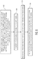
- Fig. 6 is a process flow diagram of a method for operating a radar system.
- a chirp signal having a repeating pattern of chirps is generated, each chirp in the repeating pattern of chirps having a base frequency, a chirp bandwidth, and a chirp duration, wherein the repeating pattern of chirps includes at least two chirps that differ from each other in at least one of base frequency, chirp bandwidth, and chirp duration.
- a radar signal is transmitted according to the chirp signal.
- radio frequency energy that includes a reflected portion of the radar signal is received.
- a signal that matches the repeating pattern of chirps of the chirp signal is selected for processing from the received radio frequency energy.
- the selection of the signal that matches the repeating pattern of chirps can be implemented entirely in the receiver circuitry 528 and/or the serializer circuit 534 (e.g., on the IC device 550) and in another embodiment, the selection of the signal that matches the repeating pattern of chirps can be implemented entirely in the data processor 110. In still another embodiment, the selection of the signal that matches the repeating pattern of chirps can be implemented in some combination of the receiver circuitry 528, serializer circuit 534, and/or the data processor 110.
- a unique chirp code or "fingerprint” being tied to a particular radar system (and thus to a particular vehicle), is much like a fingerprint is tied to a particular person.
- the radar system maker or governing body
- IP Internet Protocol
- a chirp code can be embedded in a radar IC device to control uniqueness of the IC device.
- a radar system is coded with the unique pattern or "fingerprint.”
- a pattern of pre-defined frequency hops can be coded into a radar IC device by a manufacturer of the IC device, e.g., making use of OTP memory.
- an IC device can be updatable “over the air” while the radar IC device is operated in a vehicle.
- a chirp pattern starts after a silent period, which is long enough to be understood as “start of pattern” or after a specific "start pattern word,” which is repetitive.
- the selection process will allow each first vehicle to use (one of) its own individual radar pattern(s).
- a "sea" of reflected radar signals it is possible to filter for any first vehicle on its specific, individual chirp pattern.
- a transmitter of a radar system emits a radar pattern of base frequencies and chirp bandwidths over its antenna and selects from the received signals only those signals where signals fall in the same pattern of base frequencies and chirp bandwidths as were emitted by the same radar system.
- multiple vehicles can transmit simultaneously in the same frequency band without creating debilitating interference as long as the vehicles use different chirp patterns.
- an embodiment of a computer program product includes a computer useable storage medium to store a computer readable program.
- the computer-useable or computer-readable storage medium can be an electronic, magnetic, optical, electromagnetic, infrared, or semiconductor system (or apparatus or device).
- Examples of non-transitory computer-useable and computer-readable storage media include a semiconductor or solid state memory, magnetic tape, a removable computer diskette, a random access memory (RAM), a read-only memory (ROM), a rigid magnetic disk, and an optical disk.
- Current examples of optical disks include a compact disk with read only memory (CD-ROM), a compact disk with read/write (CD-R/W), and a digital video disk (DVD).
- embodiments of the invention may be implemented entirely in hardware or in an implementation containing both hardware and software elements.
- the software may include but is not limited to firmware, resident software, microcode, etc.
Landscapes
- Engineering & Computer Science (AREA)
- Radar, Positioning & Navigation (AREA)
- Remote Sensing (AREA)
- Computer Networks & Wireless Communication (AREA)
- Physics & Mathematics (AREA)
- General Physics & Mathematics (AREA)
- Electromagnetism (AREA)
- Radar Systems Or Details Thereof (AREA)
Applications Claiming Priority (1)
| Application Number | Priority Date | Filing Date | Title |
|---|---|---|---|
| US16/103,866 US11187783B2 (en) | 2018-08-14 | 2018-08-14 | Radar systems and methods for operating radar systems |
Publications (2)
| Publication Number | Publication Date |
|---|---|
| EP3611537A2 true EP3611537A2 (de) | 2020-02-19 |
| EP3611537A3 EP3611537A3 (de) | 2020-02-26 |
Family
ID=67587414
Family Applications (1)
| Application Number | Title | Priority Date | Filing Date |
|---|---|---|---|
| EP19190585.0A Ceased EP3611537A3 (de) | 2018-08-14 | 2019-08-07 | Radarsysteme und verfahren zum betrieb von radarsystemen |
Country Status (3)
| Country | Link |
|---|---|
| US (1) | US11187783B2 (de) |
| EP (1) | EP3611537A3 (de) |
| CN (1) | CN110824431B (de) |
Cited By (1)
| Publication number | Priority date | Publication date | Assignee | Title |
|---|---|---|---|---|
| WO2024263284A1 (en) * | 2023-06-21 | 2024-12-26 | Qualcomm Incorporated | Signal sets for doppler and range estimation in a cellular communication system |
Families Citing this family (14)
| Publication number | Priority date | Publication date | Assignee | Title |
|---|---|---|---|---|
| DE102018222415A1 (de) * | 2018-12-20 | 2020-06-25 | Robert Bosch Gmbh | Multikanal-Analog-Digital-Wandlervorrichtung für einen optoelektronischen Sensor, Verfahren zur Signalmodulation in einem optoelektronischen Sensor und laserbasierter Entfernungs- und/oder Geschwindigkeitssensor |
| US11099265B2 (en) * | 2019-04-05 | 2021-08-24 | The Mitre Corporation | System and methods for generating and receiving doppler tolerant multipurpose communication waveforms |
| DE102019135473A1 (de) * | 2019-12-20 | 2021-06-24 | Infineon Technologies Ag | Fmcw-radar mit frequenzspringen |
| EP3862773A1 (de) * | 2020-02-04 | 2021-08-11 | Aptiv Technologies Limited | Radarvorrichtung |
| WO2022026033A1 (en) * | 2020-06-16 | 2022-02-03 | Oculii Corp. | System and method for radar interference mitigation |
| US11994575B2 (en) * | 2020-10-16 | 2024-05-28 | Texas Instruments Incorporated | Frequency modulated continuous wave radar system with interference mitigation |
| CN114584988A (zh) * | 2020-11-28 | 2022-06-03 | 华为技术有限公司 | 用于感知和通信的方法和装置 |
| EP4012443A1 (de) * | 2020-12-08 | 2022-06-15 | Veoneer Sweden AB | Fahrzeugradarsystem |
| EP4012448B1 (de) * | 2020-12-11 | 2025-05-21 | Semtech Corporation | Doppler-entfernungsmesssystem |
| JP2022126258A (ja) * | 2021-02-18 | 2022-08-30 | ルネサスエレクトロニクス株式会社 | レーダ距離計測装置およびレーダ距離計測方法 |
| US20240319332A1 (en) * | 2021-09-23 | 2024-09-26 | Intel Corporation | Apparatus, system, and method of scheduling radar transmissions |
| US11536801B1 (en) * | 2021-10-27 | 2022-12-27 | Aurora Operations, Inc. | Vehicle radar sensor utilizing non-uniform frequency modulated continuous wave (FMCW) chirps |
| DE102022128752A1 (de) * | 2022-10-28 | 2024-05-08 | Infineon Technologies Ag | Verarbeiten von Radarsignalen |
| US20250199112A1 (en) * | 2023-12-19 | 2025-06-19 | Nxp B.V. | Interference sensing and adaptation |
Citations (1)
| Publication number | Priority date | Publication date | Assignee | Title |
|---|---|---|---|---|
| WO2017165556A1 (en) | 2016-03-23 | 2017-09-28 | The Regents Of The University Of California | Interference-tolerant multiple-user radar system |
Family Cites Families (54)
| Publication number | Priority date | Publication date | Assignee | Title |
|---|---|---|---|---|
| US5410621A (en) * | 1970-12-28 | 1995-04-25 | Hyatt; Gilbert P. | Image processing system having a sampled filter |
| US4309703A (en) * | 1979-12-28 | 1982-01-05 | International Business Machines Corporation | Segmented chirp waveform implemented radar system |
| US5121408A (en) | 1989-10-16 | 1992-06-09 | Hughes Aircraft Company | Synchronization for entry to a network in a frequency hopping communication system |
| US5351053A (en) * | 1993-07-30 | 1994-09-27 | The United States Of America As Represented By The Secretary Of The Air Force | Ultra wideband radar signal processor for electronically scanned arrays |
| CA2201262C (en) * | 1997-03-27 | 2006-06-13 | Cal Corporation | Synthetic aperture radar |
| US5966371A (en) * | 1997-10-17 | 1999-10-12 | At&T Corp. | Method and system for reducing interbeam interference and multipath fading in bent-pipe satellite communications systems |
| BRPI0408255A (pt) * | 2003-03-12 | 2006-03-01 | Joule Microsystems Canada Inc | sistema de processamento de sinal e método |
| US7215278B2 (en) * | 2003-11-16 | 2007-05-08 | Preco Electronics, Inc | Radar frequency hopping |
| JP2005195450A (ja) | 2004-01-07 | 2005-07-21 | Mitsubishi Electric Corp | 電波干渉対応型レーダ装置 |
| EP1718179A2 (de) * | 2004-01-16 | 2006-11-08 | GHZ TR Corporation | Verfahren und vorrichtung für kraftfahrzeugradarsensoren |
| US8232907B2 (en) * | 2004-08-23 | 2012-07-31 | Telephonics Corporation | Step frequency high resolution radar |
| US20060239119A1 (en) * | 2005-03-08 | 2006-10-26 | Northrop Grumman Corporation | Multiple projectors for increased resolution receive beam processing of echoing sonars and radars |
| US20060227316A1 (en) * | 2005-04-06 | 2006-10-12 | Phillip Gatt | Three-dimensional imaging device |
| US7323991B1 (en) * | 2005-05-12 | 2008-01-29 | Exavera Technologies Incorporated | System and method for locating and communicating with personnel and equipment in a facility |
| US20070080852A1 (en) * | 2005-10-07 | 2007-04-12 | Blumke Joel C | Phase locked loop as linear chirp extender |
| US9019143B2 (en) * | 2006-11-30 | 2015-04-28 | Henry K. Obermeyer | Spectrometric synthetic aperture radar |
| EP2183894B1 (de) * | 2007-08-08 | 2016-03-30 | Telefonaktiebolaget LM Ericsson (publ) | Expliziten frequenzsprung verwendendes mehrträgerkommunikationssystem |
| GB2462148A (en) * | 2008-07-31 | 2010-02-03 | Mitsubishi Electric Inf Tech | Automotive FMCW radar with multiple frequency chirps |
| US20100234071A1 (en) * | 2009-03-12 | 2010-09-16 | Comsys Communication & Signal Processing Ltd. | Vehicle integrated communications system |
| KR101135982B1 (ko) | 2010-04-14 | 2012-04-17 | 국방과학연구소 | 주파수 변조 연속파 레이다에서 간섭 제거를 위한 시스템 간 동기화 방법 |
| GB2487374B (en) * | 2011-01-18 | 2016-07-27 | Thales Holdings Uk Plc | Radar system synthesising a broadband waveform from a series of narrowband chirps and accounting for Doppler of a target between chirps |
| EP2699937A4 (de) * | 2011-04-20 | 2015-02-25 | Freescale Semiconductor Inc | Empfängervorrichtung, mehrfrequenzradarsystem und fahrzeug |
| US10419907B2 (en) * | 2012-02-22 | 2019-09-17 | Qualcomm Incorporated | Proximity application discovery and provisioning |
| US9658319B2 (en) * | 2013-03-15 | 2017-05-23 | Valentine Research, Inc. | High probability of intercept radar detector |
| US10514441B2 (en) * | 2013-03-15 | 2019-12-24 | Valentine Research, Inc. | High probability of intercept radar detector |
| CN103138799B (zh) | 2013-03-21 | 2014-12-17 | 哈尔滨工业大学 | 一种低旁瓣随机跳频脉冲信号的调制方法 |
| DE102013210256A1 (de) * | 2013-06-03 | 2014-12-04 | Robert Bosch Gmbh | Interferenzunterdrückung bei einem fmcw-radar |
| KR101551811B1 (ko) * | 2014-05-19 | 2015-09-10 | 최수호 | 레이더 장치 및 그의 주파수 간섭 제거방법 |
| US9829566B2 (en) * | 2014-11-25 | 2017-11-28 | Texas Instruments Incorporated | Controlling radar transmission to enable interference mitigation |
| DE102015103149B4 (de) * | 2015-03-04 | 2024-06-06 | HELLA GmbH & Co. KGaA | Radarvorrichtung |
| US9853365B2 (en) * | 2015-05-05 | 2017-12-26 | Texas Instruments Incorporated | Dynamic programming of chirps in a frequency modulated continuous wave (FMCW) radar system |
| EP3096160B1 (de) * | 2015-05-20 | 2020-02-26 | Veoneer Sweden AB | Fmcw-kraftfahrzeug-radarsystem |
| EP3098623A1 (de) * | 2015-05-25 | 2016-11-30 | Autoliv Development AB | Fahrzeugradarsystem |
| JP6696678B2 (ja) * | 2015-09-17 | 2020-05-20 | 株式会社デンソーテン | レーダ装置、レーダ装置用の信号処理装置及び測速方法 |
| SE541162C2 (en) | 2015-10-20 | 2019-04-23 | Qamcom Tech Ab | Radar system with auxiliary channel and method |
| CN105676199B (zh) * | 2015-12-31 | 2017-12-05 | 天津大学 | 基于通信/雷达一体化的单通道lte雷达系统 |
| US10261179B2 (en) * | 2016-04-07 | 2019-04-16 | Uhnder, Inc. | Software defined automotive radar |
| US11002829B2 (en) * | 2016-04-15 | 2021-05-11 | Mediatek Inc. | Radar interference mitigation method and apparatus |
| US10334519B2 (en) * | 2016-04-22 | 2019-06-25 | Qualcomm Incorporated | Chirp signal formats and techniques |
| EP3247046B1 (de) * | 2016-05-20 | 2019-03-27 | Semtech Corporation | Drahtloskommunikationssystem mit makro-diversität |
| DE102016109910B4 (de) * | 2016-05-30 | 2017-12-07 | Infineon Technologies Ag | Radarsysteme und Verfahren zum Betreiben eines Radarsystems |
| CN106454981B (zh) | 2016-08-31 | 2019-10-11 | 天津远翥科技有限公司 | 一种随机跳频方法、通讯设备及随机跳频系统 |
| US10359504B2 (en) * | 2016-09-30 | 2019-07-23 | Veoneer Us, Inc. | Apparatus and method for mitigating interference in an automotive radar system |
| JP2018059813A (ja) * | 2016-10-05 | 2018-04-12 | 株式会社デンソーテン | レーダ装置および物標検出方法 |
| US10520583B2 (en) * | 2016-10-25 | 2019-12-31 | GM Global Technology Operations LLC | Chirp modulation via chirp slope switching |
| US10379201B2 (en) * | 2016-10-26 | 2019-08-13 | GM Global Technology Operations LLC | Radar interference mitigation and collaborative operation |
| EP3327460B1 (de) * | 2016-11-28 | 2021-05-05 | Nxp B.V. | Radar |
| CN106680790B (zh) | 2016-12-29 | 2019-05-17 | 中国电子科技集团公司第五十四研究所 | 一种伪码调相连续波雷达干扰检测方法 |
| CN107167775B (zh) | 2017-05-23 | 2020-05-19 | 哈尔滨工业大学 | 一种基于认知雷达抗多跳杂波干扰波形设计方法 |
| US10401495B2 (en) * | 2017-07-10 | 2019-09-03 | Blackmore Sensors and Analytics Inc. | Method and system for time separated quadrature detection of doppler effects in optical range measurements |
| US10788584B2 (en) * | 2017-08-22 | 2020-09-29 | Michael Leon Scott | Apparatus and method for determining defects in dielectric materials and detecting subsurface objects |
| EP3531162B1 (de) * | 2018-02-27 | 2024-01-17 | NXP USA, Inc. | Chirp-linearitätsdetektor für radar |
| IL259190A (en) * | 2018-05-07 | 2018-06-28 | Arbe Robotics Ltd | System and method of fmcw time multiplexed mimo imaging radar using multi-band chirps |
| US10802112B2 (en) * | 2018-09-17 | 2020-10-13 | United States Of America As Represented By The Secretary Of The Navy | Method, device, and system for simultaneously detecting different weapon threats using reflected radar return signals |
-
2018
- 2018-08-14 US US16/103,866 patent/US11187783B2/en active Active
-
2019
- 2019-08-07 EP EP19190585.0A patent/EP3611537A3/de not_active Ceased
- 2019-08-14 CN CN201910752324.3A patent/CN110824431B/zh active Active
Patent Citations (1)
| Publication number | Priority date | Publication date | Assignee | Title |
|---|---|---|---|---|
| WO2017165556A1 (en) | 2016-03-23 | 2017-09-28 | The Regents Of The University Of California | Interference-tolerant multiple-user radar system |
Cited By (1)
| Publication number | Priority date | Publication date | Assignee | Title |
|---|---|---|---|---|
| WO2024263284A1 (en) * | 2023-06-21 | 2024-12-26 | Qualcomm Incorporated | Signal sets for doppler and range estimation in a cellular communication system |
Also Published As
| Publication number | Publication date |
|---|---|
| CN110824431A (zh) | 2020-02-21 |
| US11187783B2 (en) | 2021-11-30 |
| US20200057136A1 (en) | 2020-02-20 |
| CN110824431B (zh) | 2023-11-28 |
| EP3611537A3 (de) | 2020-02-26 |
Similar Documents
| Publication | Publication Date | Title |
|---|---|---|
| US11187783B2 (en) | Radar systems and methods for operating radar systems | |
| KR101199169B1 (ko) | 타깃물체 감지 방법 및 레이더 장치 | |
| US11520003B2 (en) | Detection, mitigation and avoidance of mutual interference between automotive radars | |
| CN114072688A (zh) | 用于多雷达共存的干扰抑制 | |
| KR101199202B1 (ko) | 타깃 물체 감지 방법 및 레이더 장치 | |
| US10359504B2 (en) | Apparatus and method for mitigating interference in an automotive radar system | |
| US8982668B2 (en) | Semiconductor device and method of forming same for correlation detection | |
| EP3757597B1 (de) | Interferenz-vermeidung für radarsensor und radarsensor-ic | |
| US20150338507A1 (en) | Radar signal processing method and apparatus | |
| KR102678058B1 (ko) | 검출 방법, 검출 장치 및 시스템 | |
| US10036800B2 (en) | Systems and methods for using coherent noise filtering | |
| CN112639519A (zh) | 雷达系统中的两阶段信号处理的装置和方法 | |
| WO2012037680A1 (en) | Radar system with integrated communication functionality | |
| WO2019113723A1 (zh) | 激光探测方法及系统 | |
| WO1997045752A1 (en) | Virtual noise radar waveform for reduced radar detectability | |
| US10852389B2 (en) | Interference-tolerant multiple-user radar system | |
| CN111880169A (zh) | 雷达感测 | |
| JP2004271529A (ja) | レーダ信号送信方法、複数のレーダ送信器の送信方法、レーダ、及びレーダ送信器 | |
| CN119148073B (zh) | 接收信号补偿方法、装置、集成电路及无线电器件 | |
| CN112433214B (zh) | 一种雷达信号发送方法及装置 | |
| CN108027420A (zh) | 模块式车辆雷达 | |
| CN101248367A (zh) | 雷达装置和雷达站间调整方法 | |
| CN118233268A (zh) | 用于车辆中的干扰减轻的时频传感器编码的方法和系统 | |
| KR20160019802A (ko) | 전송 모드에 따른 레이더 신호 처리 방법 및 장치 | |
| KR101339755B1 (ko) | 스크램블된 신호를 송수신하는 레이더 신호 송수신 방법 및 이를 적용한 레이더 장치 |
Legal Events
| Date | Code | Title | Description |
|---|---|---|---|
| PUAI | Public reference made under article 153(3) epc to a published international application that has entered the european phase |
Free format text: ORIGINAL CODE: 0009012 |
|
| REG | Reference to a national code |
Ref country code: DE Ref legal event code: R079 Free format text: PREVIOUS MAIN CLASS: G01S0013340000 Ipc: G01S0007020000 |
|
| STAA | Information on the status of an ep patent application or granted ep patent |
Free format text: STATUS: THE APPLICATION HAS BEEN PUBLISHED |
|
| PUAL | Search report despatched |
Free format text: ORIGINAL CODE: 0009013 |
|
| AK | Designated contracting states |
Kind code of ref document: A2 Designated state(s): AL AT BE BG CH CY CZ DE DK EE ES FI FR GB GR HR HU IE IS IT LI LT LU LV MC MK MT NL NO PL PT RO RS SE SI SK SM TR |
|
| AX | Request for extension of the european patent |
Extension state: BA ME |
|
| AK | Designated contracting states |
Kind code of ref document: A3 Designated state(s): AL AT BE BG CH CY CZ DE DK EE ES FI FR GB GR HR HU IE IS IT LI LT LU LV MC MK MT NL NO PL PT RO RS SE SI SK SM TR |
|
| AX | Request for extension of the european patent |
Extension state: BA ME |
|
| RIC1 | Information provided on ipc code assigned before grant |
Ipc: G01S 13/931 20200101ALI20200117BHEP Ipc: G01S 7/02 20060101AFI20200117BHEP Ipc: G01S 13/34 20060101ALI20200117BHEP |
|
| STAA | Information on the status of an ep patent application or granted ep patent |
Free format text: STATUS: REQUEST FOR EXAMINATION WAS MADE |
|
| 17P | Request for examination filed |
Effective date: 20200826 |
|
| RBV | Designated contracting states (corrected) |
Designated state(s): AL AT BE BG CH CY CZ DE DK EE ES FI FR GB GR HR HU IE IS IT LI LT LU LV MC MK MT NL NO PL PT RO RS SE SI SK SM TR |
|
| STAA | Information on the status of an ep patent application or granted ep patent |
Free format text: STATUS: EXAMINATION IS IN PROGRESS |
|
| 17Q | First examination report despatched |
Effective date: 20210423 |
|
| STAA | Information on the status of an ep patent application or granted ep patent |
Free format text: STATUS: THE APPLICATION HAS BEEN REFUSED |
|
| 18R | Application refused |
Effective date: 20221024 |