EP3611713A1 - Système et procédé pour modifier une trajectoire de vol d'un aéronef - Google Patents
Système et procédé pour modifier une trajectoire de vol d'un aéronef Download PDFInfo
- Publication number
- EP3611713A1 EP3611713A1 EP19191085.0A EP19191085A EP3611713A1 EP 3611713 A1 EP3611713 A1 EP 3611713A1 EP 19191085 A EP19191085 A EP 19191085A EP 3611713 A1 EP3611713 A1 EP 3611713A1
- Authority
- EP
- European Patent Office
- Prior art keywords
- turn
- trajectory profile
- waypoint
- flight
- initial trajectory
- Prior art date
- Legal status (The legal status is an assumption and is not a legal conclusion. Google has not performed a legal analysis and makes no representation as to the accuracy of the status listed.)
- Withdrawn
Links
- 238000000034 method Methods 0.000 title claims abstract description 212
- 230000007704 transition Effects 0.000 claims description 27
- 238000010276 construction Methods 0.000 claims description 17
- 230000004044 response Effects 0.000 claims description 14
- 230000000977 initiatory effect Effects 0.000 claims description 5
- 230000008569 process Effects 0.000 description 141
- 238000010586 diagram Methods 0.000 description 71
- 238000012937 correction Methods 0.000 description 11
- 230000004048 modification Effects 0.000 description 10
- 238000012986 modification Methods 0.000 description 10
- 230000008859 change Effects 0.000 description 9
- 241000251468 Actinopterygii Species 0.000 description 5
- 238000012360 testing method Methods 0.000 description 4
- 101100509394 Ustilago maydis ITP1 gene Proteins 0.000 description 3
- 230000007613 environmental effect Effects 0.000 description 3
- 238000013519 translation Methods 0.000 description 3
- 230000008901 benefit Effects 0.000 description 2
- 238000001514 detection method Methods 0.000 description 2
- 230000001133 acceleration Effects 0.000 description 1
- 230000006978 adaptation Effects 0.000 description 1
- 230000006870 function Effects 0.000 description 1
- 238000006467 substitution reaction Methods 0.000 description 1
Images


Classifications
-
- B—PERFORMING OPERATIONS; TRANSPORTING
- B64—AIRCRAFT; AVIATION; COSMONAUTICS
- B64C—AEROPLANES; HELICOPTERS
- B64C13/00—Control systems or transmitting systems for actuating flying-control surfaces, lift-increasing flaps, air brakes, or spoilers
- B64C13/02—Initiating means
- B64C13/16—Initiating means actuated automatically, e.g. responsive to gust detectors
- B64C13/18—Initiating means actuated automatically, e.g. responsive to gust detectors using automatic pilot
-
- G—PHYSICS
- G08—SIGNALLING
- G08G—TRAFFIC CONTROL SYSTEMS
- G08G5/00—Traffic control systems for aircraft
- G08G5/30—Flight plan management
- G08G5/32—Flight plan management for flight plan preparation
-
- G—PHYSICS
- G08—SIGNALLING
- G08G—TRAFFIC CONTROL SYSTEMS
- G08G5/00—Traffic control systems for aircraft
- G08G5/30—Flight plan management
- G08G5/34—Flight plan management for flight plan modification
-
- B—PERFORMING OPERATIONS; TRANSPORTING
- B64—AIRCRAFT; AVIATION; COSMONAUTICS
- B64C—AEROPLANES; HELICOPTERS
- B64C13/00—Control systems or transmitting systems for actuating flying-control surfaces, lift-increasing flaps, air brakes, or spoilers
- B64C13/02—Initiating means
- B64C13/16—Initiating means actuated automatically, e.g. responsive to gust detectors
-
- G—PHYSICS
- G08—SIGNALLING
- G08G—TRAFFIC CONTROL SYSTEMS
- G08G5/00—Traffic control systems for aircraft
- G08G5/30—Flight plan management
Definitions
- the present disclosure is related to modifying a trajectory profile for an aircraft.
- An aircraft can include a flight management system that generates a trajectory profile for the aircraft based on a flight plan.
- the flight plan includes multiple waypoints (e.g., intermediate points) between a starting point of a flight (e.g., a take-off position) and a destination point (e.g., a landing position) of the flight.
- the trajectory profile is intended to produce a continuous and flyable flight path for the aircraft while complying with industry guidelines (e.g., Federal Aviation Administration (FAA) guidelines).
- FAA Federal Aviation Administration
- the trajectory profile is generated using algorithms designed to achieve the flight plan.
- the algorithms convert a flight plan into a trajectory profile which is a flyable, optimized, four-dimensional path (latitude, longitude, altitude and time) through space that the aircraft is predicted to fly.
- the algorithm is designed to produce the continuous and flyable path for the aircraft from the starting point to the destination point via the waypoints in the flight plan.
- the flight management system displays the trajectory profile on a screen within a cockpit of the aircraft, and a pilot of the aircraft can maneuver (or use an autopilot to control) the aircraft to fly the trajectory profile to reach the destination point.
- flight conditions are permissible to enable the pilot to smoothly maneuver the aircraft past each waypoint along the path.
- flight conditions can change during the flight and the pilot (or autopilot) is not able to smoothly maneuver the aircraft through each waypoint.
- the speed of the aircraft can prevent the pilot from maneuvering (or make it difficult for the pilot to maneuver) the aircraft along a particular trajectory through a particular waypoint.
- the trajectory of the aircraft can deviate from the trajectory profile.
- a method includes generating, at a processor, a flight plan of an aircraft.
- the flight plan is based on at least one waypoint and a set of operational rules associated with the aircraft.
- the method also includes generating an initial trajectory profile based on the at least one waypoint and the set of operational rules.
- the method further includes identifying an impermissible flight condition associated with the initial trajectory profile.
- the impermissible flight condition violates at least one operational rule of the set of operational rules.
- the method further includes generating a modified trajectory profile by modifying at least one aspect of the initial trajectory profile to remove the impermissible flight condition.
- the method also includes generating data representing the modified trajectory profile in at least one form that accommodates other flight management systems of the aircraft or other pilots to fly the aircraft along the modified trajectory profile.
- an aircraft includes a memory storing a set of operational rules associated with the aircraft.
- the aircraft also includes a flight management system coupled to the memory.
- the flight management system is configured to generate a flight plan of an aircraft based on at least one waypoint and the set of operational rules.
- the flight management system is also configured to generate an initial trajectory profile based on the at least one waypoint and the set of operational rules.
- the flight management system is further configured to identify an impermissible flight condition associated with the initial trajectory profile.
- the impermissible flight condition violates at least one operational rule of the set of operational rules.
- the flight management system is also configured to generate a modified trajectory profile by modifying at least one aspect of the initial trajectory profile to remove the impermissible flight condition.
- the flight management system is also configured to generate data representing the modified trajectory profile in at least one form that accommodates other flight management systems of the aircraft or other pilots to fly the aircraft along the modified trajectory profile.
- a non-transitory computer-readable medium stores instructions that, when executed by a processor, cause the processor to perform operations including generating a flight plan of an aircraft.
- the flight plan is based on at least one waypoint and a set of operational rules associated with the aircraft.
- the initial trajectory profile also includes generating an initial trajectory profile based on the at least one waypoint and the set of operational rules.
- the operations further include identifying an impermissible flight condition associated with the initial trajectory profile. The impermissible flight condition violates at least one operational rule of the set of operational rules.
- the operations also include generating a modified trajectory profile by modifying at least one aspect of the initial trajectory profile to remove the impermissible flight condition.
- the operations also include generating data representing the modified trajectory profile in at least one form that accommodates other flight management systems of the aircraft or other pilots to fly the aircraft along the modified trajectory profile.
- the initial flight plan can indicate that an aircraft is to have a turn radius of 10 kilometers to pass by a waypoint in the initial flight plan.
- impermissible flight conditions e.g., unexpected tail wind
- completion of the turn at the turn radius would violate the airplane's operational capability (e.g., the bank angle would be too steep) so the aircraft would be unable to stay on the trajectory profile.
- a flight management system can modify the initial trajectory profile during the flight to modify a turn transition (e.g., move the turn initiation point upwind on the trajectory profile 0.5 kilometers) so that the airplane can initiate the turn sooner and, therefore, comply with the rules for the given flight plan.
- a turn transition e.g., move the turn initiation point upwind on the trajectory profile 0.5 kilometers
- an initial flight plan includes an initial flight trajectory that, when followed, guides the aircraft through one or more waypoints of the initial flight plan. If an impermissible flight condition is present, maneuvering the aircraft along the initial flight trajectory can cause the autopilot to disengage.
- the speed of the aircraft could result in a turn radius that forces the aircraft to maneuver outside of the airspace required by the flight plan.
- the flight management system modifies the initial trajectory profile to generate a modified flight trajectory profile.
- the initial trajectory is modified such that the turn initiation points are relocated in a manner to produce a smooth, flyable profile that is within the allowable airplane limitations and follows closely the intent of the original trajectory profile, as a non-limiting example.
- the turn centers in the initial trajectory profile are moved in the modified trajectory profile to accommodate for an increased turn radius.
- FIG. 1 is a diagram of an aircraft 100.
- the aircraft 100 includes a cockpit 102, a cabin 104, a wing 106, and a wing 108.
- the cockpit 102 includes a system 200 that is operable to dynamically modify an initial trajectory profile of the aircraft 100 during flight in response to identifying an impermissible flight condition. For example, while the aircraft 100 is travelling between a starting point and a destination point, the system 200 can modify the initial trajectory profile (e.g. modify a turn center location) in response to a determination that flight conditions of the aircraft 100 make travelling along the initial trajectory profile "impermissible" according to one or more operational rules associated with the aircraft 100.
- the system 200 is described in greater detail with respect to FIG. 2 .
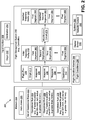
- the system 200 includes a flight management system 202 (e.g., a controller), a memory 204 coupled to the flight management system 202, an input interface 206 coupled to the flight management system 202, a flight condition monitor 208 coupled to the flight management system 202, a display screen 210 coupled to the flight management system 202, and one or more systems 290 coupled to the flight management system 202.
- the one or more systems 290 include an autopilot system 292.
- one or more components of the system 200 are integrated into the flight management system 202.
- the input interface 206 and the flight condition monitor 208 can be integrated into the flight management system 202.
- the memory 204 is a non-transitory computer-readable medium that stores instructions 220 that are executable by the flight management system 202 to perform the operations described below.
- the memory 204 also stores a set of operational rules 222 associated with the aircraft 100.
- the set of operational rules 222 includes an operational rule 224, an operational rule 226, and an operational rule 228. Although three operational rules are illustrated, in other implementations, the set of operational rules 222 can include additional (or fewer) operational rules.
- the set of operational rules 222 includes forty-five operational rules.
- the set of operational rules 222 includes a single operational rule.
- Each operational rule 224-228 of the set of operational rules 222 indicates a different rule for operating the aircraft 100.
- the operational rule 224 indicates that a turn radius for the aircraft 100 is not to be less than 5 kilometers if the aircraft 100 is travelling at a speed greater than 825 kilometers per hour.
- the operational rule 226 indicates that a turn radius for the aircraft 100 is not to be less than 10 kilometers if the aircraft 100 is travelling at a speed greater than 875 kilometers per hour.
- the operational rule 228 indicates that a turn radius for the aircraft 100 is not to be less than 15 kilometers if the aircraft 100 is travelling at a speed greater than 925 kilometers per hour.
- operational rules 224-228 are merely illustrative examples and should not be construed to as limiting. Additionally, in some implementations, one or more operational rules 224-228 of the set of operational rules 222 are included in or correspond to an industry guideline (e.g., a Federal Aviation Administration (FAA) guideline). In other implementations, the set of operational rules 222 includes rules specified by a manufacturer of the aircraft 100, rules specified by a government agency, user-entered rules, or a combination thereof.
- FAA Federal Aviation Administration
- the input interface 206 can be a keypad, a voice input device, a touch screen device, or any other device that is operable to receive an input.
- the input interface 206 is used to provide an origin 212 and a destination 214 to the flight management system 202.
- the origin 212 corresponds to a starting location of the flight
- the destination 214 corresponds to an ending location of the flight.
- a pilot or co-pilot can provide longitude and latitude coordinates of the origin 212 to the flight management system 202 via the input interface 206.
- the longitude and the latitude coordinates of the origin 212 are automatically determined using a global positioning system (GPS).
- GPS global positioning system
- the GPS determines the location of the aircraft 100 and set the location as the origin 212.
- the pilot or co-pilot can provide longitude and latitude coordinates of the destination 214 to the flight management system 202 via the input interface 206.
- the pilot provides the longitude and the latitude coordinates of a destination airport to the flight management system 202.
- the pilot provides the airport code of the destination airport to the flight management system 202, and the flight management system 202 determines the longitude and the latitude coordinates of the destination 214 based on the airport code.
- the flight management system 202 is configured to generate a flight plan 230 that, when followed, enables the aircraft 100 to safely navigate from the origin 212 to the destination 214.
- the flight plan 230 may include one or more discontinuities (e.g., based on two waypoints being too close).
- the flight plan 230 is displayed at the display screen 210.
- the flight plan 230 includes a plurality of waypoints 234-238 that the aircraft 100 is to pass through in route to the destination 214. For example, during flight, the flight plan 230 projects the aircraft 100 to pass through a waypoint 234, pass through a waypoint 236, pass through a waypoint 238, and finally arrive at the destination 214.
- "passing through" a waypoint includes flying within a particular distance of the waypoint.
- the flight management system 202 To ensure that the aircraft 100 is travelling along the projected route (e.g., through the waypoints 234-238), the flight management system 202 generates an initial trajectory profile 232 that, when followed, ensures that the aircraft 100 stays on course.
- the initial trajectory profile 232 indicates when the aircraft 100 is to turn, a turn radius for each turn of the aircraft 100, an altitude for the aircraft 100 at different instances during the flight, etc.
- the initial trajectory profile 232 includes a first segment 260, a second segment, 262, a third segment 264, and a final segment 266. Although four segments are illustrated, in other implementations, the initial trajectory profile 232 can include additional (or fewer) segments.
- Each segment 260-266 may include flight trajectory information (e.g., flight trajectory paths) that indicates initial turn points, turn centers, final turn points, turn radii, altitude, speed, etc.
- the initial trajectory profile 232 is based on the set of operational rules 222.
- the turn radius (or bank angle) for each turn in the initial trajectory profile 232 is constructed to satisfy each operational rule 224-228 in the set of operational rules 222.
- flight conditions during the course of the flight can change in such a manner to cause the aircraft 100 to violate at least one of the operational rules 224-228 if the initial trajectory profile 232 is followed.
- the flight crew may be asked by air traffic control to deviate from their flight plan (e.g., the flight plan 230) temporarily.
- the flight crew may be asked to return to their filed flight plan (e.g., the flight plan 230), but because of the position, velocity, and track angle of the aircraft 100 at the time they are asked to return to the flight plan 230, the geometry of the initial trajectory profile 232 may not allow for the path to meet the intent of the flight plan 230.
- the flight plan 230 may be populated with a Standard Instrument Departure (SID) with a series of waypoints that are closely-spaced, and the procedure designer may assume a certain level of aircraft performance to ensure the speed of the aircraft 100 is low enough to accomplish the desired trajectory.
- the aircraft 100 may have actual performance (e.g., acceleration) that exceeds the procedure designer's assumptions, and the resulting turn radii may not allow for a trajectory that meets the procedure's intent.
- SID Standard Instrument Departure
- the flight management system 202 compares flight conditions 250 of the aircraft 100 to segment information in the initial trajectory profile 232.
- the flight conditions 250 of the aircraft 100 can include the speed of the aircraft 100 at a particular instance, the expected maximum allowable bank angle, weather conditions, altitude, etc.
- the flight condition monitor 208 is configured to monitor the flight conditions 250 of the aircraft 100 and provide the flight conditions 250 to the flight management system 202.
- the flight condition monitor 208 can include a sensor (such as GPS) configured to determine the ground speed of the aircraft 100, an air data computer configured to determine the airspeed of the aircraft 100, an altimeter configured to determine an altitude of the aircraft 100, other systems, or a combination thereof.
- a sensor such as GPS
- an air data computer configured to determine the airspeed of the aircraft 100
- an altimeter configured to determine an altitude of the aircraft 100, other systems, or a combination thereof.
- the flight management system 202 is configured to compare the flight conditions 250 of the aircraft 100 to the segment information in the initial trajectory profile 232 to determine whether at least one flight condition is an impermissible flight condition.
- an "impermissible flight condition” is a flight condition that would result in the aircraft 100 violating at least one operational rule of the set of operational rules 222 if the aircraft 100 travels according to a trajectory profile. For example, if the flight conditions 250 indicate that the aircraft 100 would need to initiate a turn prior to the previous turn being completed, the flight management system 202 can indicate that the flight conditions 250 are impermissible. Examples of identifying impermissible flight conditions are described with respect to FIGS. 3-11 .
- the impermissible flight condition is identified based on a first distance between a first waypoint (e.g., the waypoint 234) and a final point of a first turn included in the initial trajectory profile 232 and a second distance between a second waypoint (e.g., the waypoint 236) and the first waypoint.
- the impermissible flight condition is identified based on a first distance between the final point of the first turn and the first waypoint (e.g., the waypoint 234) and a second distance between an initial point of a second turn included in the initial trajectory profile 232 and the first waypoint.
- the impermissible flight condition is identified based on a comparison of a bank angle included in the initial trajectory profile 232 and a bank angle determined based on an groundspeed of the aircraft 100. For example, if the required bank angle in the initial trajectory profile 232 is not achievable due to the predicted state of the aircraft causing the bank angle to be limited, an impermissible fight condition is identified.
- the impermissible flight condition can also be based on detection of an incomplete turn within the initial trajectory profile 232. As used herein, an "incomplete turn" corresponds to a turn that that has not been fully completed by the aircraft 100.
- a modification circuit 270 of the flight management system 202 In response to determining that the flight conditions 250 are impermissible according to the set of operational rules 222, a modification circuit 270 of the flight management system 202 generates a modified trajectory profile 242 by modifying at least one aspect of the initial trajectory profile 232 to remove the impermissible flight conditions.
- the second segment 262 of the initial trajectory profile 232 is modified to generate a modified second segment 282.
- the flight management system 202 can modify the initial trajectory profile 232 (e.g., modify the turn starting and end points of turns in the initial trajectory profile 232, insert straight segments between turns in the initial trajectory profile 232, relocate the position of turn centers, etc.) to generate the modified trajectory profile 242. Examples of modifying an initial trajectory profile are described with respect to FIGS.
- the display screen 210 is configured to display the modified trajectory profile 242.
- the flight management system 202 also can update at least one of the one or more systems 290 with the modified trajectory profile 242.
- the flight management system 202 can update the autopilot system 292 with the modified trajectory profile 242 to enable the aircraft 100 to fly along the modified trajectory profile 242 when the autopilot is engaged.
- Modifying at least one aspect (e.g., the second segment 262) of the initial trajectory profile 232 can include modifying a location of a center of the first turn included in the initial trajectory profile 232, modifying a location of a center of a second turn included in the initial trajectory profile 232, or both.
- the second turn may be immediately subsequent to the first turn in the initial trajectory profile 232.
- the modification circuit 270 can determine the distance to move the turn centers of each turn described herein using a closed-form technique based on one or more algorithms or using an iterative technique. According to one implementation, the location of the center of the first turn is moved along an axis that intersects the center of the first turn and a center of the second turn included in the initial trajectory profile.
- the location of the center of the first turn is moved along an axis that is parallel to an inbound course of the first turn
- the location of the center of the second turn is moved along an axis that is parallel to an outbound course of the second turn.
- modifying the second segment 262 of the initial trajectory profile 232 can also include inserting a straight segment between the first turn of the initial trajectory profile 232 and the second turn of the initial trajectory profile 232.
- the straight segment can also be rotated to modify the second segment 262 to generate the modified second segment 282.
- modifying the second segment 262 of the initial trajectory profile 232 can include performing a course capture. Additionally, modifying the second segment 262 may include projecting a line segment from an outbound course by a course capture intercept angle.
- modifying the second segment 262 can also include constructing a flight trajectory between the waypoint 234 and the waypoint 238 of the flight plan 230.
- the modification circuit 270 can bypass construction of a flight trajectory between the waypoint 234 and the waypoint 236 of the flight plan 230.
- the waypoint 236 is subsequent to the waypoint 234, and the waypoint 238 is subsequent to the waypoint 236.
- modifying the initial trajectory profile 232 can include modifying a trajectory to ignore a waypoint in the flight plan 230.
- Modifying at least one aspect of the initial trajectory profile 232 can also include generating a virtual waypoint that replaces two or more waypoints in the flight plan 230.
- a virtual waypoint 246 may replace the waypoints 234, 236.
- the aircraft 100 travels past the virtual waypoint 246 instead of the waypoints 234, 236.
- Modifying at least one aspect of the initial trajectory profile 232 can include modifying a final point of the first turn in the initial trajectory profile 232 and performing a course capture on an outbound course associated with the second turn included in the initial trajectory profile 232.
- the system 200 of FIG. 2 thus enables dynamic modification to the initial trajectory profile 232 in response to impermissible flight conditions.
- the initial trajectory profile 232 can indicate that the first turn terminates past the point that the next turn must be initiated and thus results in a violation of one of the set of operational rules 222.
- the aircraft 100 cannot start the turn for the next leg until it completes the turn for the previous leg, which violates the operational rule 226.
- the flight management system 202 modifies the initial trajectory profile 232 to generate the modified trajectory profile 242 to facilitate compliance with the operational rule 226.
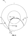
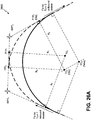
- a diagram of a flight plan 230A having a trajectory profile 232A (e.g., a non-flyable trajectory profile) based on an impermissible flight condition is shown.
- the flight plan 230A corresponds to the flight plan 230 of FIG. 2 .
- the flight plan 230A includes a first waypoint 234A, a second waypoint 236A, and a third waypoint 238A. If the aircraft 100 travels according to the trajectory profile 232A, the aircraft 100 is to fly proximate to the first waypoint 234A and turn towards the second waypoint 236A. After flying proximate to the second waypoint 236A, the aircraft 100 is to turn towards the third waypoint 238A.
- the speed of the aircraft 100 creates an impermissible flight condition (e.g., a "fish-tail" bypass condition) that results in a flight path that violates at least one operational rule (e.g., a non-flyable path).
- an "impermissible flight condition” may also be referred to as a "bypass condition.”
- the impermissible flight condition corresponds to the aircraft 100 flying at a relatively high speed that results in the aircraft completing the turn past the waypoint.
- the impermissible flight condition violates at least one operational rule of the set of operational rules 222 (e.g., the turn must be completed prior to reaching the second waypoint 236A).
- the trajectory profile 232A for the aircraft 100 between the second waypoint 236A and the third waypoint 238A is non-flyable (e.g., includes an impermissible flight condition), and following the trajectory profile 232A would result in autopilot disengaging or the flight crew unable to stay on course.
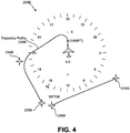
- FIG. 4 a diagram of another flight plan 230B having a trajectory profile 232B (e.g., a non-continuous trajectory profile) based on an impermissible flight condition is shown.
- the flight plan 230B corresponds to the flight plan 230 of FIG. 2 .
- the flight plan 230B includes a first waypoint 234B, a second waypoint 236B, a third waypoint 238B, and a destination 214B. If the aircraft 100 travels according to the trajectory profile 22B, the aircraft 100 is to fly past the first waypoint 234B and turn towards the second waypoint 236B. After flying past the second waypoint 236B, the aircraft 100 is to turn towards the third waypoint 238B. After flying past the third waypoint 238B, the aircraft 100 is to turn towards the destination 214B.
- an impermissible flight condition results in a flight path that violates at least one operational rule (e.g., a non-continuous path).
- at least one operational rule e.g., a non-continuous path.
- the aircraft 100 is unable to perform a turn that travels through the second waypoints 236B and the third waypoint 238B and that complies with the set of operational rules 222. Because the impermissible flight condition violates at least one operational rule of the set of operational rules 222, the impermissible flight condition creates a discontinuity between the second waypoint 236B and the third waypoint 238B.
- the impermissible flight condition can be caused by the speed of the aircraft 100, the proximity of the second waypoint 236B, the proximity of the third waypoint 238B, etc.
- a trajectory profile 232B for the aircraft 100 between the second waypoint 236B and the third waypoint 238B is non-continuous, and following the trajectory profile 232B would result in an error condition.
- FIG. 5 is a diagram that is indicative of a process 500 to determine whether an impermissible flight condition is present.
- the process 500 can be performed using a rule-based decision engine, such as flight management system 202, to detect if an impermissible flight condition is present. If an impermissible flight condition is present, one or more corrective algorithms are performed by the flight management system 202 to generate a smooth and continuous flight trajectory profile (e.g., the modified trajectory profile 242).
- a rule-based decision engine such as flight management system 202
- the process 500 determines whether a turn cannot achieve tangency with a way-line between two waypoints 234C, 236C, whether the turn is tangent on the way-line in a manner that otherwise results in a same-side turn or an S-turn, or both.
- a "same-side turn” refers to a flight condition where a turn transitions to the same side (e.g., either the left or right) for two consecutive waypoints.
- an "S-turn” refers to a flight condition where the turn transitions in opposite directions for two consecutive waypoints.
- each turn may have an initial/beginning turn point (ITP) and a final/end turn point (FTP).
- an impermissible flight condition is present if an end of a first turn (FTP1) does not lie on the way-line between the waypoint (WTP1) and a subsequent waypoint (WTP2).
- the impermissible flight condition is present if the end of the first turn (FTP1) lies on the way-line but is located outside the line bounded between the waypoint 234C and the waypoint 236C.
- the test to determine whether the impermissible flight condition exists can be performed by comparing the absolute value of respective segment lengths
- FIG. 6 is a diagram that is indicative of a process 600 to determine whether an impermissible flight condition is present.
- the process 600 can be performed using a rule-based decision engine, such as flight management system 202, to detect if an impermissible flight condition is present. If an impermissible flight condition is present, one or more corrective algorithms are performed by the flight management system 202 to generate a smooth and continuous trajectory profile (e.g., the modified trajectory profile 242).
- a rule-based decision engine such as flight management system 202
- an impermissible flight condition is present if an end of a first turn (FTP1) lies on a way-line between the waypoint 234D and a subsequent waypoint 236D, but a beginning of a second turn (ITP2) is between the end of the first turn (FTP1) and the waypoint 234D.
- FTP1 first turn
- ITP2 second turn
- ) is true, the end of the first turn (FTP1) is too far past the beginning of the second turn (ITP2) and the impermissible flight condition is present.
- AF leg for an arc to fixed (AF) leg if the course change at the start and/or end of the leg is large, and the groundspeed of the aircraft 100 is also high, then it may be impossible for the normal path construction routines to result in a path that converges on the desired flight plan intent, resulting in an impermissible flight condition.
- a bypass detection scenario for an AF leg is described in greater detail with respect to FIG. 7
- a bypass resolution for an AF leg is described in greater detail with respect to FIG. 31 .
- a test for consecutive bypass conditions can be performed by the flight management system 202.
- the flight management system 202 can execute an algorithm where an intermediate waypoint is dropped in the construction of a trajectory profile to create a smooth and continuous trajectory.
- the test includes identifying scenarios where three or more bypass waypoints (e.g., waypoints associated with an impermissible flight condition) are in adjacent flight plan legs. If there are three or more bypass waypoints in succession, a subsequent test can check to verify whether there are more than two waypoints within a turn radius of each other. Additional details are provided with respect to FIG. 22 .
- the flight management system 202 can verify whether a transition can be constructed with a straight section between the first two turns and the end of the second turn is on the arc prior to the arc departure point. If the construction cannot include a straight segment without extending the end of the second turn (FTP2) past the beginning of the third turn (ITP3), then an impermissible flight condition is present. If the entry to the arc is greater than ninety degrees, the flight management system 202 can verify whether the arc radius is greater than the turn radius for the current environment and airplane speed. If the speed and winds prevent capture and tracking the arc, an impermissible flight condition is present.
- FIG. 7 is a diagram that is indicative of a process 700 to determine whether an impermissible flight condition is present.
- the process 700 can be performed using a rule-based decision engine, such as flight management system 202, to detect if an impermissible flight condition is present. If an impermissible flight condition is present, one or more corrective algorithms can be performed by the flight management system 202 to generate a smooth and continuous flight trajectory profile (e.g., the modified trajectory profile 242).
- a rule-based decision engine such as flight management system 202
- the flight management system 202 can determine a course from the turn center of the end of a first turn (FTP1) and the angle to the AF/RF waypoint (e.g., the waypoint 236E). If the end of the first turn (FTP1) is past the waypoint 236E on the arc, then an impermissible flight condition is present. In order to determine whether the end of the first turn (FTP1) is past the waypoint 236E, the flight management system 202 can compare the cosine of the angle between the course from distance measuring equipment (DME) to the end of the first turn (FTP1) and the angle between the DME to the outbound course. An impermissible flight condition is present if the cosines are opposite signs.
- DME distance measuring equipment
- the flight management system 202 can determine the course change between the AF/RF turn center to TC1 and the AF/RF turn center to the waypoint 234E.
- An impermissible flight condition is present if the course change is smaller than the AF/RF turn center to TC1 and AF/RF turn center to the end of the first turn (FTP1).
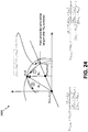
- FIG. 8 depicts a diagram that illustrates hold entry sectors 800.
- the hold entry sectors 800 include a first sector (Sector 1), a second sector (Sector 2), a third sector (Sector 3), and a fourth sector (Sector 4).
- the hold entry is associated with the aircraft 100 flying in a hold pattern through waypoint (A).
- the flight management system 202 can apply algorithms to different sectors of the hold entry sectors 800 to detect if an impermissible flight condition is present. If an impermissible flight condition is present, one or more corrective algorithms are performed by the flight management system 202 to generate a smooth and continuous trajectory profile. If the aircraft's position and velocity are such that the standard hold entry procedure does not result in successfully entering the hold, an impermissible flight condition is present.
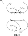
- FIG. 9 depicts diagrams 900 that are indicative of a process to determine whether an impermissible flight condition is present using the third sector (Sector 3).
- the flight management system 202 determines an angle (a) as the angle the intercept vector crosses the segment.
- the flight management system 202 determines the point (P) from the tangent of the turn radius centered at TC1 if the angle (a1) is less than or equal to ninety degrees. Otherwise, the flight management system 202 determines the point (P) from the tangent of the turn radius centered at TC2. If the angle (a) is less than or equal to thirty degrees, the flight management system 202 determines the destination point is point (4) if the intercept point is left of the point (P). Otherwise, the destination point is point (2). If the angle (a) is greater than thirty degrees and less than one hundred and fifty degrees, the flight management system 202 determines the destination point is point (3) if the intercept point is left of the point (P). Otherwise, the intercept point is point (2). If the angle (a) is greater than one hundred and fifty degrees, the flight management system 202 determines the destination point is point (3) if the intercept point is left of the point (P). Otherwise, the intercept point is point (2). If the angle (a) is greater than one hundred and fifty degrees, the flight management system
- FIG. 10 depicts a diagram 1000 that is indicative of a process to determine whether an impermissible flight condition is present using the second sector (Sector 2).
- the flight management system 202 determines an angle (a) as the angle the intercept vector crosses the segment relative to the inbound course of the holding fix. For the second sector (Sector 2), if the angle (a) is greater than zero degrees, the flight management system 202 determines the destination point is point (3). Otherwise, the destination point is point (1).
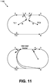
- FIG. 11 depicts diagrams 1100 that are indicative of a process to determine whether an impermissible flight condition is present using the first sector (Sector 1).
- the flight management system 202 determines an angle (a) as the angle the intercept vector crosses the segment.
- the flight management system 202 determines the point (P) from the tangent of the turn radius centered at TC2 if the angle (a) is less than or equal to ninety degrees. Otherwise, the flight management system 202 determines the point (P) from the tangent of the turn radius centered at TC1. If the angle (a) is less than or equal to one hundred and fifty degrees but greater than ninety degrees, the flight management system 202 determines the destination point is point (4) if the intercept point is left of the point (P). Otherwise, the destination point is point (1). If the angle (a) is greater than one hundred and fifty degrees, the flight management system 202 determines the destination point is point (3) if the intercept point is left of the point (P). Otherwise, the intercept point is point (1).
- the process 1200 can be performed by flight management system 202 of FIG. 2 .
- the process 1200 illustrates an example of modifying at least one aspect (e.g., the second segment 262) of the initial trajectory profile 232 by modifying at least one of a location of a center of a first turn included in the second segment 262 of the initial trajectory profile 232, modifying a location of a center of a second turn included in the second segment 262 of the initial trajectory profile 232, or both.
- the second turn may be immediately subsequent to the first turn in the initial trajectory profile 232.
- the flight management system 202 applies one or more correction algorithms to create a smooth and continuous trajectory profile (e.g., the modified trajectory profile 242) for the aircraft 100 based on the flight conditions 250.
- a smooth and continuous trajectory profile e.g., the modified trajectory profile 242
- the flight management system 202 can select an algorithm described with respect to FIG. 12 using a rule-based decision.
- one of the two turn centers is translated along the line formed between the turn centers deterministically such that the intersection of the turn arcs, independent of radius, are tangent and lie on the line formed between the two waypoints. Tangency is achieved when the length of the distance between the turn centers is (R1 +R2).
- the resulting trajectory moves the end of the first turn (FTP1) and the beginning of the second turn (ITP2) such that they meet at a tangent point on their respective turn arcs.
- FIG. 12 also illustrates a closed-form algorithm (e.g., equations) used by the modification circuit 270 to determine distance to move the turn centers.
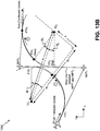
- FIGS. 13A-13B a diagram of processes 1300, 1350 for adjusting a trajectory profile is shown.
- the processes 1300, 1350 can be performed by flight management system 202 of FIG. 2 .
- the processes 1300, 1350 illustrate examples of modifying at least one aspect (e.g., the second segment 262) of the initial trajectory profile 232 by modifying at least one of a location of a center of a first turn included in the second segment 262 of the initial trajectory profile 232, modifying a location of a center of a second turn included in the second segment 262 of the initial trajectory profile 232, or both.
- the second turn may be immediately subsequent to the first turn in the initial trajectory profile 232.
- the flight management system 202 can apply one or more correction algorithms to create a smooth and continuous trajectory profile (e.g., the modified trajectory profile 242) for the aircraft 100 based on the flight conditions 250.
- a smooth and continuous trajectory profile e.g., the modified trajectory profile 242
- the flight management system 202 can select algorithms described with respect to FIGS. 13A-13B using a rule-based decision.
- the two turn centers are translated along lines parallel to their respective first turn (Turn 1) inbound course and second turn (Turn 2) outbound course.
- the resulting trajectory from the method described in Fig. 12 results in the end of the first turn (FTP1) being coincident to the beginning of the second turn (ITP2) so the aircraft 100 follows a trajectory between the waypoints where the two turns are connected.
- the resulting trajectory includes a straight section. While an autopilot could connect the two turns with a smooth, constant roll rate, pilots can have a level flight segment between the turns to allow for roll-anticipation allowance to mitigate the risk of departing the trajectory profile.
- the process 1400 can be performed by flight management system 202 of FIG. 2 .
- the process 1400 illustrates an example of modifying at least one aspect (e.g., the second segment 262) of the initial trajectory profile 232 by modifying at least one of a location of a center of a first turn included in the second segment 262 of the initial trajectory profile 232, modifying a location of a center of a second turn included in the second segment 262 of the initial trajectory profile 232, or both.
- the second turn may be immediately subsequent to the first turn in the initial trajectory profile 232.
- the process 1400 also implements a course capture routine to modify the initial trajectory profile 232.
- the flight management system 202 applies one or more correction algorithms to create a smooth and continuous trajectory profile (e.g., the modified trajectory profile 242) for the aircraft 100 based on the flight conditions 250.
- a smooth and continuous trajectory profile e.g., the modified trajectory profile 242
- the flight management system 202 can select an algorithm described with respect to FIG. 14 using a rule-based decision.
- a turn-straight-turn transition correction can be constructed for the S-turn impermissible flight condition. For example, a line is formed that connects a first turn (Turn 1) and a second turn (Turn 2) tangent to both arcs.
- the end of the first turn (FTP1) is moved from a first waypoint (WPT1) outbound course to the intersection of a new line and a corresponding arc.
- the beginning of the second turn (ITP2) is moved from the second waypoint (WPT2) inbound course to the tangent point intersection with the second turn (Turn 2) arc.
- the process 1400 adds a straight segment between two turns.
- the process 1400 can also constructs a turn-straight-turn transition correction for the S-turn impermissible flight condition.
- a point on the first waypoint (WPT1) inbound course is selected such that when a line is extended from that point at a predetermined departure angle from the inbound course, the intercept point on the second waypoint (WPT2) outbound course is approximately the same distance to the second waypoint (WPT2) as the departure point is on its inbound course to the first waypoint (WPT1).
- Course-capture maneuvers can be utilized to transition from the inbound course to the straight section and to intercept the second waypoint (WPT2) outbound course.
- first turn (ITP1) and the target point on the second waypoint (WPT2) outbound course are found by geodetic projection from the respective waypoints using an offset distance. If the construction of the bypass result in a trajectory that does not cross the way-line between the waypoints, the distance from the waypoints can be reduced to ensure that the aircraft 100 passes between the waypoints on the S-turn bypass.
- the process 1400 can be enhanced by utilizing different distances for the inbound and outbound turn points.
- the inbound and outbound distances from the waypoints are determined such that the straight segment intersects at (or near) the midpoint of the way-line between the first waypoint (WPT1) and the second waypoint (WPT2).
- the flight path of the transition is reduced and the course departure and intercept angles are within a particular range.
- the flight path is aesthetically acceptable to flight crews and the straight segment is equal to (or greater than) the roll-anticipation-distance for the second turn in the transition.
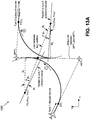
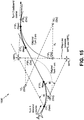
- FIG. 15 a diagram of a process 1500 for adjusting a trajectory profile is shown.
- the process 1500 can be performed by flight management system 202 of FIG. 2 .
- the process 1500 illustrates an example of modifying at least one aspect (e.g., the second segment 262) of the initial trajectory profile 232 by inserting a straight segment between a first turn included in the second segment 262 of the initial trajectory profile 232 and a second turn included in the second segment 262 of the initial trajectory profile.
- the flight management system 202 applies one or more correction algorithms to create a smooth and continuous trajectory profile (e.g., the modified trajectory profile 242) for the aircraft 100 based on the flight conditions 250.
- a smooth and continuous trajectory profile e.g., the modified trajectory profile 242
- the flight management system 202 can select an algorithm described with respect to FIG. 15 using a rule-based decision.
- a point on the inbound course is selected where a line is extended from that point at a predetermined departure angle from the inbound course that would intercept the second waypoint (WPT2). If the angle between the new segment and the second waypoint (WPT2) outbound course results in a fly-by turn (i.e., the trajectory crosses the way-line between waypoints), a course capture is formed from the new line to the second waypoint (WPT2) outbound course. If the turn from the new segment to the second waypoint (WPT2) outbound course would result in the trajectory crossing the way-line outside of the two waypoints, the departure angle can be adjusted.
- FIG. 16 a diagram of a process 1600 for adjusting a trajectory profile is shown.
- the process 1600 can be performed by flight management system 202 of FIG. 2 .
- the process 1600 illustrates an example of modifying at least one aspect (e.g., the second segment 262) of the initial trajectory profile 232 by inserting a straight segment between a first turn included in the second segment 262 of the initial trajectory profile 232 and a second turn included in the second segment 262 of the initial trajectory profile.
- the flight management system 202 applies one or more correction algorithms to create a smooth and continuous trajectory profile (e.g., the modified trajectory profile 242) for the aircraft 100 based on the flight conditions 250.
- a smooth and continuous trajectory profile e.g., the modified trajectory profile 242
- the flight management system 202 can select an algorithm described with respect to FIG. 16 using a rule-based decision.
- a point on the inbound course is selected where a line extended from that point at a predetermined departure angle from the inbound course would intercept the first waypoint (WPT1).
- the straight segment is added on a course that is parallel to the projection and that intersects the first waypoint (WPT1).
- the trajectory tracks closer to the first waypoint (WPT1) and intersects the second waypoint (WPT2) outbound course further down path.
- the departure angle is selected so that the turn can be constructed given the environmental conditions and the aircraft 100 speed.
- FIG. 17 a diagram of a process 1700 for adjusting a trajectory profile is shown.
- the process 1700 can be performed by flight management system 202 of FIG. 2 .
- the process 1700 illustrates an example of modifying at least one aspect (e.g., the second segment 262) of the initial trajectory profile 232 by inserting a straight segment between a first turn included in the second segment 262 of the initial trajectory profile 232 and a second turn included in the second segment 262 of the initial trajectory profile.
- the straight segment may be rotated.
- the flight management system 202 applies one or more correction algorithms to create a smooth and continuous trajectory profile (e.g., the modified trajectory profile 242) for the aircraft 100 based on the flight conditions 250.
- a smooth and continuous trajectory profile e.g., the modified trajectory profile 242
- the flight management system 202 can select an algorithm described with respect to FIG. 17 using a rule-based decision.
- turn centers are translated and then moved apart.
- the first turn center (TC1) is moved along a line parallel to its inbound course and the second turn center (TC2) is moved along a line parallel to its outbound course until a straight segment tangent to the two turn arcs reaches a fixed distance.
- the fixed distance can be set to accomplish a maneuver goal such as being sufficient to achieve a particular roll-anticipation-distance for a particular turn radius and speed of the aircraft 100.
- a straight segment is rotated about the tangent point on the way-line between the first waypoint (WPT1) and the second waypoint (WPT2).
- the turn centers on the respective inbound and outbound courses are translated until a desired distance of the straight segment is achieved, desired departure and intercept angles are achieved, or the total course change is reduced to achieve a desired sum of the first turn (Turn 1) course change angle and the second turn (Turn2) course change angle.
- FIG. 18 a diagram of a process 1800 for adjusting a trajectory profile is shown.
- the process 1800 can be performed by flight management system 202 of FIG. 2 .
- the process 1800 illustrates an example of modifying at least one aspect (e.g., the second segment 262) of the initial trajectory profile 232 by inserting a straight segment between a first turn included in the second segment 262 of the initial trajectory profile 232 and a second turn included in the second segment 262 of the initial trajectory profile.
- the flight management system 202 applies one or more correction algorithms to create a smooth and continuous trajectory profile (e.g., the modified trajectory profile 242) for the aircraft 100 based on the flight conditions 250.
- a smooth and continuous trajectory profile e.g., the modified trajectory profile 242
- the flight management system 202 can select an algorithm described with respect to FIG. 18 using a rule-based decision.
- turn centers are translated and then moved apart.
- the first turn center (TC1) is moved along a line parallel to its inbound course and the second turn center (TC2) is moved along a line parallel to its outbound course until a straight segment tangent to the two turn arcs reaches a fixed distance.
- the fixed distance can be set to accomplish a maneuver goal such as being sufficient to achieve a particular roll-anticipation-distance for a particular turn radius and aircraft 100 speed.
- the first turn center (TC1) and the second turn center (TC2) are moved equal distances along their respective inbound and outbound courses until the straight segment is a particular distance.
- an additional process will gauge the impact of moving the beginning of the first turn (ITP1) and the end of the second turn (FPT2) on the previous and subsequent leg transitions.
- FIG. 19 a diagram of a process 1900 for adjusting a trajectory profile is shown.
- the process 1900 can be performed by the flight management system 202 of FIG. 2 .
- the process 1900 illustrates an example of modifying at least one aspect (e.g., the second segment 262) of the initial trajectory profile 232 by projecting a line segment from an outbound course by a course capture intercept angle.
- fly-over of the first waypoint (WPT1) results in course capture that is closer to the second waypoint (WPT2) than the beginning of the second turn (ITP2) or that is past the second waypoint (WPT2). If the second waypoint (WPT2) is a fly-by transition, the process 1900 creates a course capture to the second waypoint (WPT2) outbound course using a predetermined intercept angle or angle range.
- the bearing from the waypoint (WPT1) to the waypoint (WPT2) may be given from initial construction as is the bearing from the waypoint (WPT1) to the turn center (TC1).
- the construction is the same as described with respect to FIG. 19 .
- the process 2000 can be performed by the flight management system 202 of FIG. 2 .
- the process 2000 illustrates an example of modifying at least one aspect (e.g., the second segment 262) of the initial trajectory profile 232 by constructing a flight trajectory between a first waypoint of the flight plan 230 and a third waypoint of the flight plan 230.
- the process 2000 also bypasses construction of a flight trajectory between the first waypoint and a second waypoint of the flight plan 230.
- the second waypoint is subsequent to the first waypoint
- the third waypoint is subsequent to the second waypoint.
- the process 2000 constructs a trajectory that effectively removes (or ignores) a waypoint in the flight plan 230.
- the next waypoint is bypassed (e.g., dropped) from the construction and a course capture (or nominal construction) to the subsequent flight plan leg is attempted.
- a diagram of a process 2100 for adjusting a trajectory profile is shown.
- the process 2100 can be performed by the flight management system 202 of FIG. 2 .
- the process 2100 illustrates an example of modifying at least one aspect (e.g., the second segment 262) of the initial trajectory profile 232 by constructing a flight trajectory between a first waypoint of the flight plan 230 and a third waypoint of the flight plan 230.
- the process 2100 also bypasses construction of a flight trajectory between the first waypoint and a second waypoint of the flight plan 230.
- the second waypoint is subsequent to the first waypoint
- the third waypoint is subsequent to the second waypoint.
- the process 2200 constructs a trajectory that effectively removes (or ignores) a waypoint in the flight plan 230.
- the intermediate waypoint is dropped and a trajectory to the subsequent waypoint is constructed.
- the trajectory connects the turn arc from the turn prior to the dropped waypoint to the turn arc of the waypoint after the dropped one.
- the process 2200 can be performed by the flight management system 202 of FIG. 2 .
- the process 2200 illustrates an example of modifying at least one aspect (e.g., the second segment 262) of the initial trajectory profile 232 by constructing a flight trajectory between a first waypoint of the flight plan 230 and a third waypoint of the flight plan 230.
- the process 2200 also bypasses construction of a flight trajectory between the first waypoint and a second waypoint of the flight plan 230.
- the second waypoint is subsequent to the first waypoint
- the third waypoint is subsequent to the second waypoint.
- the process 2200 constructs a trajectory that effectively removes (or ignores) a waypoint in the flight plan 230.
- the center of the waypoint cluster for all waypoints within one turn radius of each other is determined.
- a fly-over transition turn is constructed to that location, and the fly-over transition connects the inbound and outbound course and a course capture to the next waypoint.
- a virtual waypoint is added to the modified flight plan.
- the distance between each waypoint is identified as being in an impermissible flight condition and previous and subsequent waypoints to the first and last waypoints are determined and compared to the turn radius. Waypoints that are within one turn radius of points (both before and after the cluster) are determined to be within the cluster.
- FIG. 23 a diagram of a process 2300 for adjusting a flight plan is shown.
- the process 2300 can be performed by the flight management system 202 of FIG. 2 .
- the process 2300 illustrates an example of modifying at least one aspect (e.g., the second segment 262) of the initial trajectory profile 232 by inserting a straight segment between a first turn included in the second segment 262 of the initial trajectory profile 232 and a second turn included in the second segment 262 of the initial trajectory profile.
- the impermissible flight conditions are solved in a similar manner as described with respect to FIGS. 13A-19 .
- the impermissible flight condition indicates that the turn radius due to a speed of aircraft 100 and environmental conditions allows for a bank angle higher than what is called for in the leg transition
- the turn radius is increased and the transition is re-calculated. If a nominal turn transition construction uses a limit of half the course change up to twenty-five percent, a rule based decision engine can allow the twenty-five percent of the bank angle if an impermissible flight condition for a shallow angle is encountered.
- the process 2400 illustrates an example of modifying at least one aspect (e.g., the second segment 262) of the initial trajectory profile 232 by modifying at least one of a location of a center of a first turn included in the second segment 262 of the initial trajectory profile 232, modifying a location of a center of a second turn included in the second segment 262 of the initial trajectory profile 232, or both.
- the second turn may be immediately subsequent to the first turn in the initial trajectory profile 232.
- the process 2400 can be implemented by the flight management system 202 for the scenario where a same-side turn produces a "fish tail" impermissible flight condition.
- the turn center for the second turn is translated towards the turn center for the second turn along a path parallel to a line between the turn centers until the end of the first turn (FTP1) is coincident with the beginning of the second turn (ITP2).
- FIG. 24 also illustrates a closed-form algorithm (e.g., equations) used by the modification circuit 270 to determine distance to move the turn centers.
- FIG. 25 a diagram of a process 2500 for adjusting a flight plan is shown.
- the process 2500 can be implemented by the flight management system 202 for the scenario where a same-side turn produces a "fish tail" impermissible flight condition.
- the turn center for the second turn is translated on a path parallel to a line between the first waypoint (WPT1) and the second waypoint (WPT2) until a tangent is achieved on the way-line between the first waypoint (WPT1) and the second waypoint (WPT2).
- the translation is completed with a course-capture on the outbound second waypoint (WPT2) course.
- the process 2600 illustrates an example of modifying at least one aspect (e.g., the second segment 262) of the initial trajectory profile 232 by modifying at least one of a location of a center of a first turn included in the second segment 262 of the initial trajectory profile 232, modifying a location of a center of a second turn included in the second segment 262 of the initial trajectory profile 232, or both.
- the second turn may be immediately subsequent to the first turn in the initial trajectory profile 232.
- the process 2600 can be implemented by the flight management system 202 for the scenario where a same-side turn produces a "fish tail" impermissible flight condition.
- the turn center for the second turn is translated along a path parallel to a line on the second waypoint (WPT2) output course until a tangent is achieved with the arc from the first turn center (TC1).
- the second turn center (TC2) (Old) may be translated to the second turn center (TC2) (New).
- the first turn center (TC1) can be translated along a path parallel to its inbound course until tangency is achieved with the second waypoint (WPT2) outbound course.
- the first turn center (TC1) can be translated using an iterative translation or a closed-form translation.
- the process 2650 illustrates an example of modifying at least one aspect (e.g., the second segment 262) of the initial trajectory profile 232 by modifying at least one of a location of a center of a first turn included in the second segment 262 of the initial trajectory profile 232, modifying a location of a center of a second turn included in the second segment 262 of the initial trajectory profile 232, or both.
- the second turn may be immediately subsequent to the first turn in the initial trajectory profile 232.
- the process 2650 can be implemented by the flight management system 202 for the scenario where a same-side turn produces a "fish tail" impermissible flight condition.
- a diagram of a process 2700 for adjusting a trajectory profile is shown.
- the process 2700 can be implemented by the flight management system 202 for the scenario where a same-side turn produces an impermissible flight condition.
- the construction is for the first waypoint (WPT1) overfly transition that intercepts the first waypoint (WPT1) outbound course closer to the second waypoint (WPT2) than the beginning of the second turn (ITP2).
- WPT1 first waypoint
- WPT2 second waypoint
- ITP2 beginning of the second turn
- a co-tangent straight segment is added at a point tangent to both arcs.
- a diagram of a process 2800 for adjusting a trajectory profile is shown.
- the process 2800 can be implemented by the flight management system 202 for the scenario where a same-side turn produces an impermissible flight condition.
- the process 2800 illustrates an example of modifying at least one aspect (e.g., the second segment 262) of the initial trajectory profile 232 by modifying a final point of a first turn included in the second segment 262 of the initial trajectory profile 232 and performing a course capture on an outbound course associated with a second turn included in the second segment 262 of the initial trajectory profile 232.
- the impermissible flight condition is removed by continuing the first turn until a course capture to intercept the second waypoint (WPT2) outbound course can be constructed.
- the process 2800 can also be applied to a scenario where the waypoint (WPT1) is an under-fly and the speed of the aircraft 100 is high enough that the trajectory results in course capture past the waypoint (WPT2).
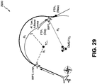
- the process 2900 illustrates an example of modifying at least one aspect (e.g., the second segment 262) of the initial trajectory profile 232 by inserting a straight segment between a first turn included in the second segment 262 of the initial trajectory profile 232 and a second turn included in the second segment 262 of the initial trajectory profile.
- the process 2900 can be implemented by the flight management system 202 for the scenario where a same-side turn produces an impermissible flight condition.
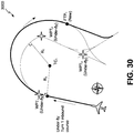
- FIG. 30 a diagram of a process 3000 for adjusting a trajectory profile is shown.
- the process 3000 can be implemented by the flight management system 202 for the scenario where a same-side turn produces a "fish tail" impermissible flight condition.
- the process 3000 illustrates an example of modifying at least one aspect (e.g., the second segment 262) of the initial trajectory profile 232 by modifying a final point of a first turn included in the second segment 262 of the initial trajectory profile 232 and performing a course capture on an outbound course associated with a second turn included in the second segment 262 of the initial trajectory profile 232.
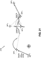
- a diagram of a process 3100 for adjusting a trajectory profile is shown.
- the process 3100 uses a nominal fly-over to circular arc transition to adjust the trajectory profile.
- the process 3100 for adjusting a trajectory profile can be implemented by the flight management system 202 for the scenario where a same-side turn produces an impermissible flight condition.
- the impermissible flight condition is resolved by constructing a course capture to the second waypoint (WPT2) outbound course.
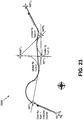
- FIG. 32 a diagram for of a process 3200 of adjusting a trajectory profile is shown.
- the process 3200 can be implemented by the flight management system 202.
- the initial turn radius for the first turn is too large to capture the AF leg between the first waypoint (WPT1) and the second waypoint (WPT2).
- WPT1 first waypoint
- WPT2 second waypoint
- an impermissible flight condition is created.
- the first turn is extended and a course capture to the second waypoint outbound course is constructed.
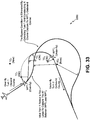
- FIG. 33 a diagram for of a process 3300 of adjusting a trajectory profile is shown.
- the process 3300 can be implemented by the flight management system 202.
- the initial turn radius for the first turn is too large to capture the AF leg between the first waypoint (WPT1) and the second waypoint (WPT2).
- WPT1 first waypoint
- WPT2 second waypoint
- an impermissible flight condition is created.
- the first turn is extended and a course capture to the second waypoint outbound course is constructed.
- a flowchart of a method 3400 for modifying a flight trajectory profile in response to identification of an impermissible flight condition can be performed by the system 200 of FIG. 2 .
- the method 3400 can be performed by the flight management system 202.
- the method 3400 includes generating, at a processor, a flight plan of an aircraft, at 3402.
- the flight plan is based on at least one waypoint and a set of operational rules associated with the aircraft.
- the flight management system 202 generates the flight plan 230.
- the flight plan 230 is based on the waypoints 234-238 and the set of operational rules 222.
- the method 3400 also includes generating, at the processor, an initial trajectory profile based on the at least one waypoint and the set of operational rules, at 3404. For example, referring to FIG. 2 , the flight management system 202 generate the initial trajectory profile 232 based on the at least one waypoint and the set of operational rules 222.
- the method 3400 also includes identifying, at the processor, an impermissible flight condition associated with the initial trajectory profile, at 3406.
- the impermissible flight condition violates at least one operational rule of the set of operational rules. For example, referring to FIG. 2 , the flight management system 202 identifies an impermissible flight condition associated with the initial trajectory profile 232. The impermissible flight condition violates at least one of the operational rules 224-228.
- the impermissible flight condition is identified based on a flight time associated with the initial trajectory profile exceeding a particular flight time or a flight distance associated with the initial trajectory profile exceeding a particular flight distance. According to another implementation, the impermissible flight condition is identified based on a turn radius of a particular turn within the initial trajectory profile being greater than a threshold radius associated with capturing a hold.
- the method 3400 also includes generating, at the processor, a modified trajectory profile by modifying at least one aspect of the initial trajectory profile to remove the impermissible flight condition, at 3408.
- the modification circuit 270 generates the modified trajectory profile 242 by modifying the initial trajectory profile 232 to remove the impermissible flight condition.
- the method 3400 also includes initiating display of the modified trajectory profile, at 3408.
- the flight management system 202 displays the modified trajectory profile 242 on the display screen 210. Identifying the impermissible flight condition and modifying the at least one aspect of the initial trajectory profile may include performing at least one flight plan correction (e.g., one of the techniques described with respect to FIGS. 1-33 ) with a path capture transition.
- modifying the at least one aspect of the initial trajectory profile includes translating a turn center for a second turn within the initial trajectory profile until an end of a first turn within the initial trajectory profile is coincident with a beginning of the second turn.
- modifying the at least one aspect of the initial trajectory profile includes translating a turn center for a second turn within the initial trajectory profile along a path parallel to a line between a first waypoint of the flight plan and a second waypoint of the flight plan.
- modifying the at least one aspect of the initial trajectory profile includes translating a turn center for a second turn within the initial trajectory profile along a path parallel to a line outbound from a second waypoint of the flight plan.
- modifying the at least one aspect of the initial trajectory profile includes adding a co-tangent straight segment at one or more points tangent to a first turn arc and a second turn arc based on a first waypoint overfly transition intercepting a first waypoint outbound course closer to a second waypoint than to a beginning of a second turn.
- the method 3400 includes determining whether at least three bypass waypoints are included in adjacent legs of the flight plan.
- the method 3400 may also include in response to a determination that at least three bypass waypoints are included in the adjacent legs, determining whether more than two bypass waypoints of the at least three bypass waypoints are located within a particular turn radius.
- the method 3400 may also include grouping the more than two bypass waypoints based on a centroid of the more than two bypass waypoints.
- the method 3400 of FIG. 34 thus enables dynamic modification to the initial trajectory profile 232 in response to impermissible flight conditions.
- the initial trajectory profile 232 can indicate that the first turn has a turn radius of 5 kilometers to pass through the waypoint 234.
- impermissible flight conditions e.g., an airspeed of 880 kilometers per hour
- completion of the first turn at the turn radius can result in an error condition.
- completing the first turn at the airspeed of 880 kilometers per hour violates the operational rule 226.
- the flight management system 202 modifies the initial trajectory profile 232 to comply with the operational rule 226.
- FIG. 35 is a block diagram of an illustrative implementation of the aircraft 100 that includes components of the system 200.
- the aircraft 100 includes an airframe 3518, a plurality of systems 3520, and an interior 3522.
- the plurality of systems 3520 include one or more of a propulsion system 3524, an electrical system 3526, an environmental system 3528, the system 200, and a sensor system 3532.
- the sensor system 3532 includes one or more sensors onboard the aircraft 100 and configured to generate sensor data during operation of the aircraft 100.
- the system 200 includes the flight management system 202, the memory 204, the input interface 206, the flight condition monitor 208, and the display screen 210.
Landscapes
- Engineering & Computer Science (AREA)
- Aviation & Aerospace Engineering (AREA)
- Physics & Mathematics (AREA)
- General Physics & Mathematics (AREA)
- Automation & Control Theory (AREA)
- Traffic Control Systems (AREA)
- Navigation (AREA)
Applications Claiming Priority (1)
| Application Number | Priority Date | Filing Date | Title |
|---|---|---|---|
| US16/103,454 US10867520B2 (en) | 2018-08-14 | 2018-08-14 | System and method to modify an aircraft flight trajectory |
Publications (1)
| Publication Number | Publication Date |
|---|---|
| EP3611713A1 true EP3611713A1 (fr) | 2020-02-19 |
Family
ID=67658639
Family Applications (1)
| Application Number | Title | Priority Date | Filing Date |
|---|---|---|---|
| EP19191085.0A Withdrawn EP3611713A1 (fr) | 2018-08-14 | 2019-08-09 | Système et procédé pour modifier une trajectoire de vol d'un aéronef |
Country Status (5)
| Country | Link |
|---|---|
| US (1) | US10867520B2 (fr) |
| EP (1) | EP3611713A1 (fr) |
| JP (1) | JP7525987B2 (fr) |
| CN (1) | CN110827581B (fr) |
| CA (1) | CA3051925A1 (fr) |
Families Citing this family (12)
| Publication number | Priority date | Publication date | Assignee | Title |
|---|---|---|---|---|
| DE102018120675A1 (de) * | 2018-08-23 | 2020-02-27 | Autel Robotics Europe Gmbh | Verfahren, Vorrichtung und System zum Betreiben von Wegpunkt, Bodenstation und computerlesbarem Speichermedium |
| JP7602145B2 (ja) | 2020-03-27 | 2024-12-18 | セントラル硝子株式会社 | ノボラック樹脂、エポキシ樹脂、感光性樹脂組成物、硬化性樹脂組成物、硬化物、電子デバイス、ノボラック樹脂の製造方法、エポキシ樹脂の製造方法および活性エステル樹脂の製造方法 |
| RU2749167C1 (ru) * | 2020-07-02 | 2021-06-07 | Акционерное общество "Российская самолетостроительная корпорация "МиГ" (АО "РСК "МиГ") | Способ управления самолетом при возврате на аэродром в условиях экономии топлива |
| CN111968410A (zh) * | 2020-08-14 | 2020-11-20 | 成都民航空管科技发展有限公司 | 基于atc系统的航班经过航路点识别方法、系统及介质 |
| US12462695B2 (en) * | 2022-03-29 | 2025-11-04 | Glass Aviation Holdings, Inc. | Conflict resolution for malformed blocked airspace designations |
| CN115031897A (zh) * | 2022-04-20 | 2022-09-09 | 中国航空工业集团公司沈阳飞机设计研究所 | 一种飞机试飞测试方法 |
| CN114721417B (zh) * | 2022-04-21 | 2025-07-04 | 四川傲势科技有限公司 | 无人飞行器测绘航线规划方法、系统、设备及介质 |
| CN114912222B (zh) * | 2022-05-17 | 2025-06-24 | 中电科航空电子有限公司 | 用于飞行管理系统的航段间过渡段航迹的构造方法和装置 |
| CN115292895B (zh) * | 2022-07-05 | 2025-12-19 | 电子科技大学长三角研究院(湖州) | 一种基于水平航线和地速剖面的飞行时间间隔计算方法 |
| US12293671B2 (en) | 2022-11-21 | 2025-05-06 | Rockwell Collins, Inc. | Flight plan rules based conformity check |
| US12586473B2 (en) * | 2023-09-07 | 2026-03-24 | The Boeing Company | System and method to build a flyable holding pattern entry trajectory when the available space is limited |
| CN118031973B (zh) * | 2024-04-12 | 2024-07-23 | 四川腾盾科技有限公司 | 一种基于无人机约束的航路简化方法、设备及介质 |
Citations (5)
| Publication number | Priority date | Publication date | Assignee | Title |
|---|---|---|---|---|
| US5646854A (en) * | 1989-11-14 | 1997-07-08 | Honeywell Inc. | Lateral guidance transition control apparatus for aircraft area navigation systems |
| US20020133294A1 (en) * | 1993-05-14 | 2002-09-19 | Farmakis Tom S. | Satellite based collision avoidance system |
| US20120150367A1 (en) * | 2010-12-09 | 2012-06-14 | Airbus Operations (S.A.S.) | Method And Device For Automatically Monitoring The Ability Of An Aircraft To Follow A Flight Trajectory With At Least One Turn |
| US20140257602A1 (en) * | 2013-03-06 | 2014-09-11 | Gulfstream Aerospace Corporation | Methods and systems for instructing an aircraft to perform a go-around maneuver |
| EP3089115A1 (fr) * | 2015-04-29 | 2016-11-02 | Rosemount Aerospace Inc. | Détection d'anomalie de fonctionnement d'un aéronef |
Family Cites Families (17)
| Publication number | Priority date | Publication date | Assignee | Title |
|---|---|---|---|---|
| US6606034B1 (en) * | 1995-07-31 | 2003-08-12 | Honeywell International Inc. | Terrain awareness system |
| US7568662B1 (en) * | 2001-09-12 | 2009-08-04 | Honeywell International Inc. | Emergency flight control system |
| ITRM20020371A1 (it) * | 2002-07-10 | 2004-01-12 | Maurizio Catello Pennarola | Sistema di gestione della navigazione di velivoli fuori rotta e comunicazioni di allarme. |
| DE50312100D1 (de) * | 2003-07-25 | 2009-12-17 | Nikolai Alekseevich Baranov | Verfahren und system zur verhinderung, dass ein fl eines wirbelerzeugers eindringt |
| EP1653250B1 (fr) * | 2003-07-25 | 2011-02-23 | Nikolai Alekseevich Baranov | Systeme integre de securite en matiere de tourbillons pour aeronef |
| US7908078B2 (en) * | 2005-10-13 | 2011-03-15 | Honeywell International Inc. | Perspective-view visual runway awareness and advisory display |
| FR2896072B1 (fr) * | 2006-01-11 | 2013-07-05 | Airbus France | Procede et dispositif d'aide au pilotage d'un aeronef. |
| DE102006033347A1 (de) * | 2006-07-19 | 2008-01-31 | Eads Deutschland Gmbh | Verfahren zur Ermittlung optimierter Bewegungsbahnen von Fahrzeugen |
| US8527118B2 (en) * | 2007-10-17 | 2013-09-03 | The Boeing Company | Automated safe flight vehicle |
| US8538673B2 (en) * | 2008-10-31 | 2013-09-17 | Czech Technical University In Prague | System and method for planning/replanning collision free flight plans in real or accelerated time |
| US8718839B2 (en) * | 2009-12-06 | 2014-05-06 | Evolved Aircraft Systems, L.L.C. | Method and apparatus for automatically controlling aircraft flight control trim systems |
| FR2985074B1 (fr) | 2011-12-22 | 2014-02-21 | Thales Sa | Procede et dispositif pour la determination d'une trajectoire laterale d'un aeronef et systeme de gestion du vol associe |
| RU2550887C2 (ru) * | 2013-06-13 | 2015-05-20 | Открытое акционерное общество "Научно-производственный комплекс "ЭЛАРА" имени Г.А. Ильенко" (ОАО "ЭЛАРА") | Бортовая интегрированная система информационной поддержки экипажа и когнитивный формат представления полетной информации на этапе "взлет" многодвигательного воздушного судна |
| CN103970143B (zh) * | 2013-08-27 | 2017-03-29 | 清华大学 | 一种无人飞行器自主巡点飞行的智能优化方法 |
| EP3170166A1 (fr) | 2014-07-18 | 2017-05-24 | The University Of Malta | Optimisation de trajectoire de vol et outil de visualisation |
| FR3036511B1 (fr) * | 2015-05-19 | 2019-12-20 | Dassault Aviation | Systeme de visualisation d'informations relatives a un vol d'un aeronef et procede associe |
| AT517443B1 (de) * | 2015-07-14 | 2021-04-15 | Frequentis Ag | Verfahren zur Anzeige von relevanten Informationen in einem Luftfahrzeug |
-
2018
- 2018-08-14 US US16/103,454 patent/US10867520B2/en active Active
-
2019
- 2019-08-09 JP JP2019147383A patent/JP7525987B2/ja active Active
- 2019-08-09 EP EP19191085.0A patent/EP3611713A1/fr not_active Withdrawn
- 2019-08-13 CN CN201910747419.6A patent/CN110827581B/zh active Active
- 2019-08-13 CA CA3051925A patent/CA3051925A1/fr active Pending
Patent Citations (5)
| Publication number | Priority date | Publication date | Assignee | Title |
|---|---|---|---|---|
| US5646854A (en) * | 1989-11-14 | 1997-07-08 | Honeywell Inc. | Lateral guidance transition control apparatus for aircraft area navigation systems |
| US20020133294A1 (en) * | 1993-05-14 | 2002-09-19 | Farmakis Tom S. | Satellite based collision avoidance system |
| US20120150367A1 (en) * | 2010-12-09 | 2012-06-14 | Airbus Operations (S.A.S.) | Method And Device For Automatically Monitoring The Ability Of An Aircraft To Follow A Flight Trajectory With At Least One Turn |
| US20140257602A1 (en) * | 2013-03-06 | 2014-09-11 | Gulfstream Aerospace Corporation | Methods and systems for instructing an aircraft to perform a go-around maneuver |
| EP3089115A1 (fr) * | 2015-04-29 | 2016-11-02 | Rosemount Aerospace Inc. | Détection d'anomalie de fonctionnement d'un aéronef |
Also Published As
| Publication number | Publication date |
|---|---|
| US20200058225A1 (en) | 2020-02-20 |
| CN110827581A (zh) | 2020-02-21 |
| CN110827581B (zh) | 2023-06-27 |
| US10867520B2 (en) | 2020-12-15 |
| JP7525987B2 (ja) | 2024-07-31 |
| CA3051925A1 (fr) | 2020-02-14 |
| JP2020057369A (ja) | 2020-04-09 |
| BR102019016788A2 (pt) | 2020-04-07 |
Similar Documents
| Publication | Publication Date | Title |
|---|---|---|
| EP3611713A1 (fr) | Système et procédé pour modifier une trajectoire de vol d'un aéronef | |
| US11619953B2 (en) | Three dimensional aircraft autonomous navigation under constraints | |
| US8126599B2 (en) | Method of calculating approach trajectory for aircraft | |
| US7917254B2 (en) | Aircraft guidance using localizer capture criteria for rectilinear displacement data | |
| EP3671395A1 (fr) | Système de décollage à faible visibilité/sans visibilité | |
| CN104252797B (zh) | 基于虚拟管制员的空域仿真方法及其装置 | |
| US11842629B2 (en) | Dynamic radar vectoring guidance methods and systems | |
| KR20230078097A (ko) | 도심항공교통 실증 관리를 위한 디지털 트윈 기술에 기반한 3d 가시화 방법 | |
| US7941251B2 (en) | Consistent localizer captures | |
| US7698027B2 (en) | Aircraft path verification assistance method | |
| KR101731609B1 (ko) | 계기 착륙 장치 및 공항지리정보를 이용한 공항주변 항공기 궤적 생성 시스템 | |
| Paielli | Trajectory Specification for Terminal Air Traffic: Conflict Detection and Resolution | |
| JP2020184316A (ja) | 都市航空ビークルの航法性能 | |
| Salgueiro et al. | Identifying, Visualizing and Communicating Constraints in PBN Flight Procedure Design | |
| Paielli | Evaluation of tactical conflict resolution algorithms for enroute airspace | |
| Korn et al. | Stepwise integration of UAS in non-segregated airspace-The potential of tailored uas atm procedures | |
| US12586473B2 (en) | System and method to build a flyable holding pattern entry trajectory when the available space is limited | |
| Masson et al. | Diverging Engine Failure Paths on Standard Instrument Departures | |
| Adami et al. | An energy management display for general aviation safety enhancements | |
| Hansman et al. | Block 1 procedure recommendations for Logan Airport community noise reduction | |
| BR102019016788B1 (pt) | Método para modificar uma trajetória de voo de aeronave, aeronave, meio legível por computador não transitório | |
| CN114898597A (zh) | 一种目视航线导航方法及系统 | |
| Hrdlička et al. | Design of the vertical trajectory for arrival and departure routes at Prague airport | |
| Miquel | Airspeed And Height Profiles Setting For Time Based Flight Arrivals | |
| Degtyarev et al. | Broadcast algorithms for detection and decentralized resolution of unsafe approach of airborne aircraft based on the force field method |
Legal Events
| Date | Code | Title | Description |
|---|---|---|---|
| PUAI | Public reference made under article 153(3) epc to a published international application that has entered the european phase |
Free format text: ORIGINAL CODE: 0009012 |
|
| STAA | Information on the status of an ep patent application or granted ep patent |
Free format text: STATUS: THE APPLICATION HAS BEEN PUBLISHED |
|
| AK | Designated contracting states |
Kind code of ref document: A1 Designated state(s): AL AT BE BG CH CY CZ DE DK EE ES FI FR GB GR HR HU IE IS IT LI LT LU LV MC MK MT NL NO PL PT RO RS SE SI SK SM TR |
|
| AX | Request for extension of the european patent |
Extension state: BA ME |
|
| STAA | Information on the status of an ep patent application or granted ep patent |
Free format text: STATUS: REQUEST FOR EXAMINATION WAS MADE |
|
| 17P | Request for examination filed |
Effective date: 20200805 |
|
| RBV | Designated contracting states (corrected) |
Designated state(s): AL AT BE BG CH CY CZ DE DK EE ES FI FR GB GR HR HU IE IS IT LI LT LU LV MC MK MT NL NO PL PT RO RS SE SI SK SM TR |
|
| STAA | Information on the status of an ep patent application or granted ep patent |
Free format text: STATUS: EXAMINATION IS IN PROGRESS |
|
| 17Q | First examination report despatched |
Effective date: 20220103 |
|
| RAP3 | Party data changed (applicant data changed or rights of an application transferred) |
Owner name: THE BOEING COMPANY |
|
| STAA | Information on the status of an ep patent application or granted ep patent |
Free format text: STATUS: THE APPLICATION HAS BEEN WITHDRAWN |
|
| 18W | Application withdrawn |
Effective date: 20241212 |