EP3611769A1 - Système de récupération de chaleur - Google Patents
Système de récupération de chaleur Download PDFInfo
- Publication number
- EP3611769A1 EP3611769A1 EP19190903.5A EP19190903A EP3611769A1 EP 3611769 A1 EP3611769 A1 EP 3611769A1 EP 19190903 A EP19190903 A EP 19190903A EP 3611769 A1 EP3611769 A1 EP 3611769A1
- Authority
- EP
- European Patent Office
- Prior art keywords
- heat
- vapour
- target application
- spreader
- recovery system
- Prior art date
- Legal status (The legal status is an assumption and is not a legal conclusion. Google has not performed a legal analysis and makes no representation as to the accuracy of the status listed.)
- Withdrawn
Links
Images


Classifications
-
- F—MECHANICAL ENGINEERING; LIGHTING; HEATING; WEAPONS; BLASTING
- F28—HEAT EXCHANGE IN GENERAL
- F28D—HEAT-EXCHANGE APPARATUS, NOT PROVIDED FOR IN ANOTHER SUBCLASS, IN WHICH THE HEAT-EXCHANGE MEDIA DO NOT COME INTO DIRECT CONTACT
- F28D15/00—Heat-exchange apparatus with the intermediate heat-transfer medium in closed tubes passing into or through the conduit walls ; Heat-exchange apparatus employing intermediate heat-transfer medium or bodies
- F28D15/02—Heat-exchange apparatus with the intermediate heat-transfer medium in closed tubes passing into or through the conduit walls ; Heat-exchange apparatus employing intermediate heat-transfer medium or bodies in which the medium condenses and evaporates, e.g. heat pipes
- F28D15/0266—Heat-exchange apparatus with the intermediate heat-transfer medium in closed tubes passing into or through the conduit walls ; Heat-exchange apparatus employing intermediate heat-transfer medium or bodies in which the medium condenses and evaporates, e.g. heat pipes with separate evaporating and condensing chambers connected by at least one conduit; Loop-type heat pipes; with multiple or common evaporating or condensing chambers
-
- F—MECHANICAL ENGINEERING; LIGHTING; HEATING; WEAPONS; BLASTING
- F01—MACHINES OR ENGINES IN GENERAL; ENGINE PLANTS IN GENERAL; STEAM ENGINES
- F01N—GAS-FLOW SILENCERS OR EXHAUST APPARATUS FOR MACHINES OR ENGINES IN GENERAL; GAS-FLOW SILENCERS OR EXHAUST APPARATUS FOR INTERNAL-COMBUSTION ENGINES
- F01N5/00—Exhaust or silencing apparatus combined or associated with devices profiting by exhaust energy
- F01N5/02—Exhaust or silencing apparatus combined or associated with devices profiting by exhaust energy the devices using heat
- F01N5/025—Exhaust or silencing apparatus combined or associated with devices profiting by exhaust energy the devices using heat the device being thermoelectric generators
-
- F—MECHANICAL ENGINEERING; LIGHTING; HEATING; WEAPONS; BLASTING
- F01—MACHINES OR ENGINES IN GENERAL; ENGINE PLANTS IN GENERAL; STEAM ENGINES
- F01N—GAS-FLOW SILENCERS OR EXHAUST APPARATUS FOR MACHINES OR ENGINES IN GENERAL; GAS-FLOW SILENCERS OR EXHAUST APPARATUS FOR INTERNAL-COMBUSTION ENGINES
- F01N3/00—Exhaust or silencing apparatus having means for purifying, rendering innocuous, or otherwise treating exhaust
- F01N3/02—Exhaust or silencing apparatus having means for purifying, rendering innocuous, or otherwise treating exhaust for cooling, or for removing solid constituents of, exhaust
- F01N3/0205—Exhaust or silencing apparatus having means for purifying, rendering innocuous, or otherwise treating exhaust for cooling, or for removing solid constituents of, exhaust using heat exchangers
-
- F—MECHANICAL ENGINEERING; LIGHTING; HEATING; WEAPONS; BLASTING
- F01—MACHINES OR ENGINES IN GENERAL; ENGINE PLANTS IN GENERAL; STEAM ENGINES
- F01N—GAS-FLOW SILENCERS OR EXHAUST APPARATUS FOR MACHINES OR ENGINES IN GENERAL; GAS-FLOW SILENCERS OR EXHAUST APPARATUS FOR INTERNAL-COMBUSTION ENGINES
- F01N3/00—Exhaust or silencing apparatus having means for purifying, rendering innocuous, or otherwise treating exhaust
- F01N3/02—Exhaust or silencing apparatus having means for purifying, rendering innocuous, or otherwise treating exhaust for cooling, or for removing solid constituents of, exhaust
- F01N3/04—Exhaust or silencing apparatus having means for purifying, rendering innocuous, or otherwise treating exhaust for cooling, or for removing solid constituents of, exhaust using liquids
-
- F—MECHANICAL ENGINEERING; LIGHTING; HEATING; WEAPONS; BLASTING
- F02—COMBUSTION ENGINES; HOT-GAS OR COMBUSTION-PRODUCT ENGINE PLANTS
- F02G—HOT GAS OR COMBUSTION-PRODUCT POSITIVE-DISPLACEMENT ENGINE PLANTS; USE OF WASTE HEAT OF COMBUSTION ENGINES; NOT OTHERWISE PROVIDED FOR
- F02G5/00—Profiting from waste heat of combustion engines, not otherwise provided for
- F02G5/02—Profiting from waste heat of exhaust gases
-
- F—MECHANICAL ENGINEERING; LIGHTING; HEATING; WEAPONS; BLASTING
- F28—HEAT EXCHANGE IN GENERAL
- F28D—HEAT-EXCHANGE APPARATUS, NOT PROVIDED FOR IN ANOTHER SUBCLASS, IN WHICH THE HEAT-EXCHANGE MEDIA DO NOT COME INTO DIRECT CONTACT
- F28D15/00—Heat-exchange apparatus with the intermediate heat-transfer medium in closed tubes passing into or through the conduit walls ; Heat-exchange apparatus employing intermediate heat-transfer medium or bodies
- F28D15/02—Heat-exchange apparatus with the intermediate heat-transfer medium in closed tubes passing into or through the conduit walls ; Heat-exchange apparatus employing intermediate heat-transfer medium or bodies in which the medium condenses and evaporates, e.g. heat pipes
-
- F—MECHANICAL ENGINEERING; LIGHTING; HEATING; WEAPONS; BLASTING
- F28—HEAT EXCHANGE IN GENERAL
- F28D—HEAT-EXCHANGE APPARATUS, NOT PROVIDED FOR IN ANOTHER SUBCLASS, IN WHICH THE HEAT-EXCHANGE MEDIA DO NOT COME INTO DIRECT CONTACT
- F28D15/00—Heat-exchange apparatus with the intermediate heat-transfer medium in closed tubes passing into or through the conduit walls ; Heat-exchange apparatus employing intermediate heat-transfer medium or bodies
- F28D15/02—Heat-exchange apparatus with the intermediate heat-transfer medium in closed tubes passing into or through the conduit walls ; Heat-exchange apparatus employing intermediate heat-transfer medium or bodies in which the medium condenses and evaporates, e.g. heat pipes
- F28D15/0233—Heat-exchange apparatus with the intermediate heat-transfer medium in closed tubes passing into or through the conduit walls ; Heat-exchange apparatus employing intermediate heat-transfer medium or bodies in which the medium condenses and evaporates, e.g. heat pipes the conduits having a particular shape, e.g. non-circular cross-section, annular
-
- F—MECHANICAL ENGINEERING; LIGHTING; HEATING; WEAPONS; BLASTING
- F28—HEAT EXCHANGE IN GENERAL
- F28D—HEAT-EXCHANGE APPARATUS, NOT PROVIDED FOR IN ANOTHER SUBCLASS, IN WHICH THE HEAT-EXCHANGE MEDIA DO NOT COME INTO DIRECT CONTACT
- F28D15/00—Heat-exchange apparatus with the intermediate heat-transfer medium in closed tubes passing into or through the conduit walls ; Heat-exchange apparatus employing intermediate heat-transfer medium or bodies
- F28D15/02—Heat-exchange apparatus with the intermediate heat-transfer medium in closed tubes passing into or through the conduit walls ; Heat-exchange apparatus employing intermediate heat-transfer medium or bodies in which the medium condenses and evaporates, e.g. heat pipes
- F28D15/0275—Arrangements for coupling heat-pipes together or with other structures, e.g. with base blocks; Heat pipe cores
-
- F—MECHANICAL ENGINEERING; LIGHTING; HEATING; WEAPONS; BLASTING
- F28—HEAT EXCHANGE IN GENERAL
- F28D—HEAT-EXCHANGE APPARATUS, NOT PROVIDED FOR IN ANOTHER SUBCLASS, IN WHICH THE HEAT-EXCHANGE MEDIA DO NOT COME INTO DIRECT CONTACT
- F28D15/00—Heat-exchange apparatus with the intermediate heat-transfer medium in closed tubes passing into or through the conduit walls ; Heat-exchange apparatus employing intermediate heat-transfer medium or bodies
- F28D15/02—Heat-exchange apparatus with the intermediate heat-transfer medium in closed tubes passing into or through the conduit walls ; Heat-exchange apparatus employing intermediate heat-transfer medium or bodies in which the medium condenses and evaporates, e.g. heat pipes
- F28D15/04—Heat-exchange apparatus with the intermediate heat-transfer medium in closed tubes passing into or through the conduit walls ; Heat-exchange apparatus employing intermediate heat-transfer medium or bodies in which the medium condenses and evaporates, e.g. heat pipes with tubes having a capillary structure
-
- F—MECHANICAL ENGINEERING; LIGHTING; HEATING; WEAPONS; BLASTING
- F28—HEAT EXCHANGE IN GENERAL
- F28D—HEAT-EXCHANGE APPARATUS, NOT PROVIDED FOR IN ANOTHER SUBCLASS, IN WHICH THE HEAT-EXCHANGE MEDIA DO NOT COME INTO DIRECT CONTACT
- F28D15/00—Heat-exchange apparatus with the intermediate heat-transfer medium in closed tubes passing into or through the conduit walls ; Heat-exchange apparatus employing intermediate heat-transfer medium or bodies
- F28D15/02—Heat-exchange apparatus with the intermediate heat-transfer medium in closed tubes passing into or through the conduit walls ; Heat-exchange apparatus employing intermediate heat-transfer medium or bodies in which the medium condenses and evaporates, e.g. heat pipes
- F28D15/06—Control arrangements therefor
-
- F—MECHANICAL ENGINEERING; LIGHTING; HEATING; WEAPONS; BLASTING
- F28—HEAT EXCHANGE IN GENERAL
- F28D—HEAT-EXCHANGE APPARATUS, NOT PROVIDED FOR IN ANOTHER SUBCLASS, IN WHICH THE HEAT-EXCHANGE MEDIA DO NOT COME INTO DIRECT CONTACT
- F28D21/00—Heat-exchange apparatus not covered by any of the groups F28D1/00 - F28D20/00
- F28D21/0001—Recuperative heat exchangers
- F28D21/0003—Recuperative heat exchangers the heat being recuperated from exhaust gases
-
- H—ELECTRICITY
- H10—SEMICONDUCTOR DEVICES; ELECTRIC SOLID-STATE DEVICES NOT OTHERWISE PROVIDED FOR
- H10N—ELECTRIC SOLID-STATE DEVICES NOT OTHERWISE PROVIDED FOR
- H10N10/00—Thermoelectric devices comprising a junction of dissimilar materials, i.e. devices exhibiting Seebeck or Peltier effects
- H10N10/10—Thermoelectric devices comprising a junction of dissimilar materials, i.e. devices exhibiting Seebeck or Peltier effects operating with only the Peltier or Seebeck effects
- H10N10/13—Thermoelectric devices comprising a junction of dissimilar materials, i.e. devices exhibiting Seebeck or Peltier effects operating with only the Peltier or Seebeck effects characterised by the heat-exchanging means at the junction
-
- F—MECHANICAL ENGINEERING; LIGHTING; HEATING; WEAPONS; BLASTING
- F01—MACHINES OR ENGINES IN GENERAL; ENGINE PLANTS IN GENERAL; STEAM ENGINES
- F01N—GAS-FLOW SILENCERS OR EXHAUST APPARATUS FOR MACHINES OR ENGINES IN GENERAL; GAS-FLOW SILENCERS OR EXHAUST APPARATUS FOR INTERNAL-COMBUSTION ENGINES
- F01N2240/00—Combination or association of two or more different exhaust treating devices, or of at least one such device with an auxiliary device, not covered by indexing codes F01N2230/00 or F01N2250/00, one of the devices being
- F01N2240/02—Combination or association of two or more different exhaust treating devices, or of at least one such device with an auxiliary device, not covered by indexing codes F01N2230/00 or F01N2250/00, one of the devices being a heat exchanger
-
- F—MECHANICAL ENGINEERING; LIGHTING; HEATING; WEAPONS; BLASTING
- F28—HEAT EXCHANGE IN GENERAL
- F28D—HEAT-EXCHANGE APPARATUS, NOT PROVIDED FOR IN ANOTHER SUBCLASS, IN WHICH THE HEAT-EXCHANGE MEDIA DO NOT COME INTO DIRECT CONTACT
- F28D21/00—Heat-exchange apparatus not covered by any of the groups F28D1/00 - F28D20/00
- F28D2021/0019—Other heat exchangers for particular applications; Heat exchange systems not otherwise provided for
- F28D2021/008—Other heat exchangers for particular applications; Heat exchange systems not otherwise provided for for vehicles
Definitions
- PCMs solid to liquid phase change materials
- Another aspect of the present disclosure relates to the use of the device in target applications where overheating and thermal dilution are to be avoided, namely in highly variable thermal sources.
- An example will be thermoelectric generation in the recovery of waste heat involved in engine operation and industrial processes.
- the materials of the disclosure are important insofar as they affect the thermal, mechanical and corrosion resistance of the application.
- thermoelectric generators While this is an especially useful application of the disclosure, it is not limited to this use and the thermoelectric devices are not mandatory. They are commercially available.
- This disclosure includes a concept which may be applied in different ways to several different products incorporating energy recovery such as vehicles, industrial processes, etc.
- the heat transferred by phase change will only occur when boiling conditions are met within the chambers.
- the heat which crosses the heat spreader coming from the hot source heat exchanger to the target application will cross it exclusively by conduction (or no heat transfer will occur if conduction is not present) across the heat spreader body, as long as the temperature of the phase change fluid inside the chambers does not achieve the boiling temperature and once this temperature is achieved, the spreading feature will start occurring along the length of the heat spreader, with vapour being generated in the hotter regions of the heat spreader where boiling conditions are present and with the vapour spreading along the length of the heat spreader, condensing and releasing its latent heat in the cooler regions of the heat spreader where condensation conditions are present, and transmitting this heat to the target application.
- the return of the condensates to the vaporization region and the wetting of these surfaces is made by
- the inner surface of these chambers has capillarity pumping inducing structures such as wicks, meshes, metallic foams, arteries, grooves, channels and other suitable features to promote capillary flow as found in established heat pipe and vapour chamber literature.
- capillarity pumping inducing structures such as wicks, meshes, metallic foams, arteries, grooves, channels and other suitable features to promote capillary flow as found in established heat pipe and vapour chamber literature.
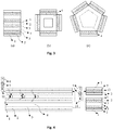
- the geometry of these chambers should be suitable both for the capillary pumping effect and for withstanding the inner pressure present inside the system.
- the geometry should also be optimized to minimize thermal resistance to the conductive heat transfer across the spreader which is a feature of this embodiment.
- the extra volume downstream of the excess vapour condenser (5) is called the expansion tank volume (6).
- the expansion tank volume (6) function is to increase the operating pressure and temperature stability of the system if desired. Unlike the buffer volume (11), it cannot be used for vapour accumulation, only non-condensable gas, because it is located downstream of the excess vapour condenser (5), which will condense all vapour reaching it. However, this component is important for pressure stabilization (the higher the total volume, the more stable will be the system pressure and temperature).
- the buffer volume (11) and expansion tank volume (6) volumes are optional and may have any shape or volume. On one hand, the thermal load peaks will be wasted if there is no buffer volume (11). On the other hand, the pressure and temperature will be less controllable if the expansion tank volume (6) is small or non-existent.
- embodiment #2 does not have a relevant conductive heat transfer area across the thickness of the heat spreader unlike the latter, which will rely on conduction across the spreader to transfer heat across the spreader (see Fig. 1 ). However, this causes them to operate in a substantially different way. While embodiment #1 will practically only use the heat spreader (3) to spread the excess heat ( Fig.1 ), embodiment #2 will use the heat spreader (3) to spread all the heat along its active length, from the hot source to the target application.
- the line through which the condensates will fall back to the evaporator (8) should be located at the lowest point of the standalone heat spreader/condenser (12). It can be the liquid line (10) located at the downstream end of the system, as displayed in Fig. 7 . With this configuration the system will display a loop characteristic, eliminating the typical entrainment limit of thermosiphons and heat pipes. Nevertheless, another alternative is for the condensates to fall back towards the upstream tip of the standalone heat spreader (condenser) (12) and descend back towards the evaporator (8) through a dedicated liquid line (10) or through the same line (9) from which the vapour is reaching the condenser (8). Under these conditions, the liquid will return in counter-current to the vapour having the entrainment limitation, but allowing the vapour line to be always wet, favouring a rapid vaporization.
Landscapes
- Engineering & Computer Science (AREA)
- Mechanical Engineering (AREA)
- General Engineering & Computer Science (AREA)
- Physics & Mathematics (AREA)
- Thermal Sciences (AREA)
- Life Sciences & Earth Sciences (AREA)
- Sustainable Development (AREA)
- Chemical & Material Sciences (AREA)
- Combustion & Propulsion (AREA)
- Heat-Exchange Devices With Radiators And Conduit Assemblies (AREA)
Applications Claiming Priority (1)
| Application Number | Priority Date | Filing Date | Title |
|---|---|---|---|
| PT11110618 | 2018-08-08 |
Publications (1)
| Publication Number | Publication Date |
|---|---|
| EP3611769A1 true EP3611769A1 (fr) | 2020-02-19 |
Family
ID=67587576
Family Applications (1)
| Application Number | Title | Priority Date | Filing Date |
|---|---|---|---|
| EP19190903.5A Withdrawn EP3611769A1 (fr) | 2018-08-08 | 2019-08-08 | Système de récupération de chaleur |
Country Status (2)
| Country | Link |
|---|---|
| US (1) | US20200049053A1 (fr) |
| EP (1) | EP3611769A1 (fr) |
Families Citing this family (4)
| Publication number | Priority date | Publication date | Assignee | Title |
|---|---|---|---|---|
| JP2021158169A (ja) * | 2020-03-25 | 2021-10-07 | 学校法人東京理科大学 | 熱電装置 |
| CN114370354A (zh) * | 2021-12-31 | 2022-04-19 | 中国重汽集团济南动力有限公司 | 一种适用于发动机变工况的余热回收系统及方法 |
| CN115297680A (zh) * | 2022-08-02 | 2022-11-04 | 宁波生久科技有限公司 | 新型热压转换式均温板散热器 |
| CN121969432A (zh) * | 2023-07-25 | 2026-05-01 | 曼特捕集公司 | 用于热回收的系统和方法 |
Citations (11)
| Publication number | Priority date | Publication date | Assignee | Title |
|---|---|---|---|---|
| JP2001280870A (ja) * | 2000-03-30 | 2001-10-10 | Furukawa Electric Co Ltd:The | 可変コンダクタンスヒートパイプ |
| EP1855328A2 (fr) * | 2006-05-10 | 2007-11-14 | The Boeing Company | Générateur d'alimentation thermoélectrique avec réglage de température incorporé |
| US20090126772A1 (en) * | 2004-10-27 | 2009-05-21 | Hino Motors Ltd | Thermoelectric generating device |
| DE102008037342A1 (de) * | 2008-08-11 | 2010-03-04 | Siemens Aktiengesellschaft | Kühlung eines Kühlfluids in Hybrid-Fahrzeugen |
| US20100186398A1 (en) | 2006-08-31 | 2010-07-29 | Norbert Huber | Thermoelectric facility comprising a thermoelectric generator and means for limiting the temperature on the generator |
| US20100186399A1 (en) * | 2006-08-31 | 2010-07-29 | Huettinger Simon | Thermoelectric facility comprising a thermoelectric generator and means for limiting the temperature on the generator |
| WO2012038917A1 (fr) | 2010-09-23 | 2012-03-29 | Basf Se | Protection thermique de module thermoélectrique et/ou de générateur thermoélectrique au moyen de matériaux à changement de phase |
| DE102012202150A1 (de) | 2012-02-13 | 2013-08-14 | Behr Gmbh & Co. Kg | Vorrichtung zum thermoelektrischen Erzeugen von Energie für ein Fahrzeug |
| US20140007915A1 (en) | 2012-07-03 | 2014-01-09 | Robert Bosch Gmbh | Thermoelectric generator for a vehicle and heat storage device for a thermoelectric generator of a vehicle |
| CN105429510A (zh) | 2015-11-30 | 2016-03-23 | 河南工程学院 | 基于热管技术的发动机冷却系统能量回收装置及方法 |
| CN106329998A (zh) | 2016-09-13 | 2017-01-11 | 天津大学 | 一种采用相变材料的汽车尾气余热温差发电装置 |
-
2019
- 2019-08-08 US US16/535,895 patent/US20200049053A1/en not_active Abandoned
- 2019-08-08 EP EP19190903.5A patent/EP3611769A1/fr not_active Withdrawn
Patent Citations (11)
| Publication number | Priority date | Publication date | Assignee | Title |
|---|---|---|---|---|
| JP2001280870A (ja) * | 2000-03-30 | 2001-10-10 | Furukawa Electric Co Ltd:The | 可変コンダクタンスヒートパイプ |
| US20090126772A1 (en) * | 2004-10-27 | 2009-05-21 | Hino Motors Ltd | Thermoelectric generating device |
| EP1855328A2 (fr) * | 2006-05-10 | 2007-11-14 | The Boeing Company | Générateur d'alimentation thermoélectrique avec réglage de température incorporé |
| US20100186398A1 (en) | 2006-08-31 | 2010-07-29 | Norbert Huber | Thermoelectric facility comprising a thermoelectric generator and means for limiting the temperature on the generator |
| US20100186399A1 (en) * | 2006-08-31 | 2010-07-29 | Huettinger Simon | Thermoelectric facility comprising a thermoelectric generator and means for limiting the temperature on the generator |
| DE102008037342A1 (de) * | 2008-08-11 | 2010-03-04 | Siemens Aktiengesellschaft | Kühlung eines Kühlfluids in Hybrid-Fahrzeugen |
| WO2012038917A1 (fr) | 2010-09-23 | 2012-03-29 | Basf Se | Protection thermique de module thermoélectrique et/ou de générateur thermoélectrique au moyen de matériaux à changement de phase |
| DE102012202150A1 (de) | 2012-02-13 | 2013-08-14 | Behr Gmbh & Co. Kg | Vorrichtung zum thermoelektrischen Erzeugen von Energie für ein Fahrzeug |
| US20140007915A1 (en) | 2012-07-03 | 2014-01-09 | Robert Bosch Gmbh | Thermoelectric generator for a vehicle and heat storage device for a thermoelectric generator of a vehicle |
| CN105429510A (zh) | 2015-11-30 | 2016-03-23 | 河南工程学院 | 基于热管技术的发动机冷却系统能量回收装置及方法 |
| CN106329998A (zh) | 2016-09-13 | 2017-01-11 | 天津大学 | 一种采用相变材料的汽车尾气余热温差发电装置 |
Also Published As
| Publication number | Publication date |
|---|---|
| US20200049053A1 (en) | 2020-02-13 |
Similar Documents
| Publication | Publication Date | Title |
|---|---|---|
| EP3611769A1 (fr) | Système de récupération de chaleur | |
| EP2238400B1 (fr) | Caloducs intégrant des échangeurs thermiques à microcanaux | |
| US8109325B2 (en) | Heat transfer system | |
| Vasiliev | Heat pipes in modern heat exchangers | |
| Maydanik | Loop heat pipes | |
| Cai et al. | Experimental investigation on a novel multi-branch heat pipe for multi-heat source electronics | |
| CN104040280B (zh) | 冷却装置 | |
| CN111642103A (zh) | 高热流密度多孔热沉流动冷却装置 | |
| US20070227703A1 (en) | Evaporatively cooled thermosiphon | |
| US20040206479A1 (en) | Heat transfer system | |
| JP2013506109A (ja) | 熱エネルギー貯蔵材料を利用した熱伝達システム | |
| Bai et al. | Experimental investigation of startup behaviors of a dual compensation chamber loop heat pipe with insufficient fluid inventory | |
| US20150308750A1 (en) | Slug Pump Heat Pipe | |
| Hendrayanto et al. | Experimental study on Start-Up and heat transfer characteristics in loop heat pipes with dual heat sources for battery thermal management system | |
| US9899789B2 (en) | Thermal management systems | |
| CN100334931C (zh) | 用于cpl的带散热片的平面式毛细芯蒸发器 | |
| JP4998933B2 (ja) | 熱伝達システム | |
| WO2013069318A1 (fr) | Chauffe-eau solaire | |
| CN100449244C (zh) | 传热系统 | |
| JP2011027321A (ja) | ループ型ヒートパイプ、電子装置 | |
| EP1549897B1 (fr) | Evaporateur pour systeme de transfert thermique | |
| AU2014250674B2 (en) | Heat pipes incorporating microchannel heat exchangers | |
| MXPA06004692A (es) | Fabricacion de un sistema de transferencia de calor. | |
| CN116424579A (zh) | 用于航天器散热的两相流体回路系统 | |
| Egbo et al. | A review of composite wicks for high heat flux heat pipes and vapor chambers |
Legal Events
| Date | Code | Title | Description |
|---|---|---|---|
| PUAI | Public reference made under article 153(3) epc to a published international application that has entered the european phase |
Free format text: ORIGINAL CODE: 0009012 |
|
| STAA | Information on the status of an ep patent application or granted ep patent |
Free format text: STATUS: THE APPLICATION HAS BEEN PUBLISHED |
|
| AK | Designated contracting states |
Kind code of ref document: A1 Designated state(s): AL AT BE BG CH CY CZ DE DK EE ES FI FR GB GR HR HU IE IS IT LI LT LU LV MC MK MT NL NO PL PT RO RS SE SI SK SM TR |
|
| AX | Request for extension of the european patent |
Extension state: BA ME |
|
| STAA | Information on the status of an ep patent application or granted ep patent |
Free format text: STATUS: REQUEST FOR EXAMINATION WAS MADE |
|
| 17P | Request for examination filed |
Effective date: 20200819 |
|
| RBV | Designated contracting states (corrected) |
Designated state(s): AL AT BE BG CH CY CZ DE DK EE ES FI FR GB GR HR HU IE IS IT LI LT LU LV MC MK MT NL NO PL PT RO RS SE SI SK SM TR |
|
| STAA | Information on the status of an ep patent application or granted ep patent |
Free format text: STATUS: EXAMINATION IS IN PROGRESS |
|
| 17Q | First examination report despatched |
Effective date: 20220408 |
|
| STAA | Information on the status of an ep patent application or granted ep patent |
Free format text: STATUS: THE APPLICATION IS DEEMED TO BE WITHDRAWN |
|
| 18D | Application deemed to be withdrawn |
Effective date: 20220823 |