EP3611802B1 - Multifunktionaler hochspannungsverbinder und batterieprodukt - Google Patents
Multifunktionaler hochspannungsverbinder und batterieprodukt Download PDFInfo
- Publication number
- EP3611802B1 EP3611802B1 EP19188026.9A EP19188026A EP3611802B1 EP 3611802 B1 EP3611802 B1 EP 3611802B1 EP 19188026 A EP19188026 A EP 19188026A EP 3611802 B1 EP3611802 B1 EP 3611802B1
- Authority
- EP
- European Patent Office
- Prior art keywords
- connecting portion
- length direction
- voltage connector
- pedestal
- mating terminals
- Prior art date
- Legal status (The legal status is an assumption and is not a legal conclusion. Google has not performed a legal analysis and makes no representation as to the accuracy of the status listed.)
- Active
Links
Images








Classifications
-
- H—ELECTRICITY
- H01—ELECTRIC ELEMENTS
- H01R—ELECTRICALLY-CONDUCTIVE CONNECTIONS; STRUCTURAL ASSOCIATIONS OF A PLURALITY OF MUTUALLY-INSULATED ELECTRICAL CONNECTING ELEMENTS; COUPLING DEVICES; CURRENT COLLECTORS
- H01R13/00—Details of coupling devices of the kinds covered by groups H01R12/70 or H01R24/00 - H01R33/00
- H01R13/46—Bases; Cases
- H01R13/502—Bases; Cases composed of different pieces
-
- H—ELECTRICITY
- H01—ELECTRIC ELEMENTS
- H01R—ELECTRICALLY-CONDUCTIVE CONNECTIONS; STRUCTURAL ASSOCIATIONS OF A PLURALITY OF MUTUALLY-INSULATED ELECTRICAL CONNECTING ELEMENTS; COUPLING DEVICES; CURRENT COLLECTORS
- H01R13/00—Details of coupling devices of the kinds covered by groups H01R12/70 or H01R24/00 - H01R33/00
- H01R13/02—Contact members
- H01R13/10—Sockets for co-operation with pins or blades
- H01R13/11—Resilient sockets
- H01R13/113—Resilient sockets co-operating with pins or blades having a rectangular transverse section
-
- H—ELECTRICITY
- H01—ELECTRIC ELEMENTS
- H01M—PROCESSES OR MEANS, e.g. BATTERIES, FOR THE DIRECT CONVERSION OF CHEMICAL ENERGY INTO ELECTRICAL ENERGY
- H01M50/00—Constructional details or processes of manufacture of the non-active parts of electrochemical cells other than fuel cells, e.g. hybrid cells
- H01M50/50—Current conducting connections for cells or batteries
- H01M50/502—Interconnectors for connecting terminals of adjacent batteries; Interconnectors for connecting cells outside a battery casing
-
- H—ELECTRICITY
- H01—ELECTRIC ELEMENTS
- H01R—ELECTRICALLY-CONDUCTIVE CONNECTIONS; STRUCTURAL ASSOCIATIONS OF A PLURALITY OF MUTUALLY-INSULATED ELECTRICAL CONNECTING ELEMENTS; COUPLING DEVICES; CURRENT COLLECTORS
- H01R11/00—Individual connecting elements providing two or more spaced connecting locations for conductive members which are, or may be, thereby interconnected, e.g. end pieces for wires or cables supported by the wire or cable and having means for facilitating electrical connection to some other wire, terminal, or conductive member, blocks of binding posts
- H01R11/11—End pieces or tapping pieces for wires, supported by the wire and for facilitating electrical connection to some other wire, terminal or conductive member
- H01R11/28—End pieces consisting of a ferrule or sleeve
- H01R11/281—End pieces consisting of a ferrule or sleeve for connections to batteries
- H01R11/287—Intermediate parts between battery post and cable end piece
-
- H—ELECTRICITY
- H01—ELECTRIC ELEMENTS
- H01R—ELECTRICALLY-CONDUCTIVE CONNECTIONS; STRUCTURAL ASSOCIATIONS OF A PLURALITY OF MUTUALLY-INSULATED ELECTRICAL CONNECTING ELEMENTS; COUPLING DEVICES; CURRENT COLLECTORS
- H01R13/00—Details of coupling devices of the kinds covered by groups H01R12/70 or H01R24/00 - H01R33/00
- H01R13/02—Contact members
- H01R13/22—Contacts for co-operating by abutting
- H01R13/24—Contacts for co-operating by abutting resilient; resiliently-mounted
-
- H—ELECTRICITY
- H01—ELECTRIC ELEMENTS
- H01R—ELECTRICALLY-CONDUCTIVE CONNECTIONS; STRUCTURAL ASSOCIATIONS OF A PLURALITY OF MUTUALLY-INSULATED ELECTRICAL CONNECTING ELEMENTS; COUPLING DEVICES; CURRENT COLLECTORS
- H01R13/00—Details of coupling devices of the kinds covered by groups H01R12/70 or H01R24/00 - H01R33/00
- H01R13/40—Securing contact members in or to a base or case; Insulating of contact members
- H01R13/42—Securing in a demountable manner
-
- H—ELECTRICITY
- H01—ELECTRIC ELEMENTS
- H01R—ELECTRICALLY-CONDUCTIVE CONNECTIONS; STRUCTURAL ASSOCIATIONS OF A PLURALITY OF MUTUALLY-INSULATED ELECTRICAL CONNECTING ELEMENTS; COUPLING DEVICES; CURRENT COLLECTORS
- H01R13/00—Details of coupling devices of the kinds covered by groups H01R12/70 or H01R24/00 - H01R33/00
- H01R13/46—Bases; Cases
- H01R13/53—Bases or cases for heavy duty; Bases or cases for high voltage with means for preventing corona or arcing
-
- H—ELECTRICITY
- H01—ELECTRIC ELEMENTS
- H01R—ELECTRICALLY-CONDUCTIVE CONNECTIONS; STRUCTURAL ASSOCIATIONS OF A PLURALITY OF MUTUALLY-INSULATED ELECTRICAL CONNECTING ELEMENTS; COUPLING DEVICES; CURRENT COLLECTORS
- H01R13/00—Details of coupling devices of the kinds covered by groups H01R12/70 or H01R24/00 - H01R33/00
- H01R13/58—Means for relieving strain on wire connection, e.g. cord grip, for avoiding loosening of connections between wires and terminals within a coupling device terminating a cable
- H01R13/5804—Means for relieving strain on wire connection, e.g. cord grip, for avoiding loosening of connections between wires and terminals within a coupling device terminating a cable comprising a separate cable clamping part
- H01R13/5812—Means for relieving strain on wire connection, e.g. cord grip, for avoiding loosening of connections between wires and terminals within a coupling device terminating a cable comprising a separate cable clamping part the cable clamping being achieved by mounting the separate part on the housing of the coupling device
-
- H—ELECTRICITY
- H01—ELECTRIC ELEMENTS
- H01R—ELECTRICALLY-CONDUCTIVE CONNECTIONS; STRUCTURAL ASSOCIATIONS OF A PLURALITY OF MUTUALLY-INSULATED ELECTRICAL CONNECTING ELEMENTS; COUPLING DEVICES; CURRENT COLLECTORS
- H01R13/00—Details of coupling devices of the kinds covered by groups H01R12/70 or H01R24/00 - H01R33/00
- H01R13/648—Protective earth or shield arrangements on coupling devices, e.g. anti-static shielding
- H01R13/658—High frequency shielding arrangements, e.g. against EMI [Electro-Magnetic Interference] or EMP [Electro-Magnetic Pulse]
- H01R13/6581—Shield structure
- H01R13/6582—Shield structure with resilient means for engaging mating connector
-
- H—ELECTRICITY
- H01—ELECTRIC ELEMENTS
- H01R—ELECTRICALLY-CONDUCTIVE CONNECTIONS; STRUCTURAL ASSOCIATIONS OF A PLURALITY OF MUTUALLY-INSULATED ELECTRICAL CONNECTING ELEMENTS; COUPLING DEVICES; CURRENT COLLECTORS
- H01R13/00—Details of coupling devices of the kinds covered by groups H01R12/70 or H01R24/00 - H01R33/00
- H01R13/66—Structural association with built-in electrical component
- H01R13/68—Structural association with built-in electrical component with built-in fuse
- H01R13/696—Structural association with built-in electrical component with built-in fuse the fuse being integral with the terminal, e.g. pin or socket
-
- H—ELECTRICITY
- H01—ELECTRIC ELEMENTS
- H01M—PROCESSES OR MEANS, e.g. BATTERIES, FOR THE DIRECT CONVERSION OF CHEMICAL ENERGY INTO ELECTRICAL ENERGY
- H01M50/00—Constructional details or processes of manufacture of the non-active parts of electrochemical cells other than fuel cells, e.g. hybrid cells
- H01M50/20—Mountings; Secondary casings or frames; Racks, modules or packs; Suspension devices; Shock absorbers; Transport or carrying devices; Holders
- H01M50/204—Racks, modules or packs for multiple batteries or multiple cells
-
- Y—GENERAL TAGGING OF NEW TECHNOLOGICAL DEVELOPMENTS; GENERAL TAGGING OF CROSS-SECTIONAL TECHNOLOGIES SPANNING OVER SEVERAL SECTIONS OF THE IPC; TECHNICAL SUBJECTS COVERED BY FORMER USPC CROSS-REFERENCE ART COLLECTIONS [XRACs] AND DIGESTS
- Y02—TECHNOLOGIES OR APPLICATIONS FOR MITIGATION OR ADAPTATION AGAINST CLIMATE CHANGE
- Y02E—REDUCTION OF GREENHOUSE GAS [GHG] EMISSIONS, RELATED TO ENERGY GENERATION, TRANSMISSION OR DISTRIBUTION
- Y02E60/00—Enabling technologies; Technologies with a potential or indirect contribution to GHG emissions mitigation
- Y02E60/10—Energy storage using batteries
Definitions
- the present invention relates to the field of connector technology, and particularly relates to a multifunctional high-voltage connector and a battery product.
- the features of the preamble of the independent claim are known from US 2009/309689 A1 .
- Related technologies are known from CN 204 304 143 U , US 2009/047814 A1 and US 2018/076575 A1 .
- the second contact segment 1322 may be provided with: a first avoiding hole 13221 aligned with the first connection hole 13212 in the length direction L; and a second avoiding hole 13222 aligned with the third connection hole 13214 in the length direction L.
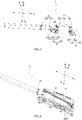
- the upper cover 11 may comprise: an outer shell 111; an inner shell 112 fixed inside the outer shell 111, and the inner shell 112 is provided with an opening facing the outer shell 111 in the height direction H; and at least one insulation sheet 113, each insulation sheet 113 is fixed to the inner shell 112.
- Each conductive connection portion 132 and the main body portion 131 of the conductive connection structure 13 are accommodated in the inner shell 112 via the opening of the inner shell 112, the insulation sheet 113 isolates the conductive connection structure 13 from the outer shell 111 at the opening of the inner shell 112.
- the inner shell 112 may have: a first receiving portion 1121; second receiving portions 1122 respectively formed on both sides of the first receiving portion 1121 in the length direction L; and extending portions 1123 respectively formed outside the second receiving portions 1122 in the length direction L.
- the first receiving portion 1121 and the second receiving portion 1122 of the inner shell 112 are communicated with the opening of the inner shell 112, the first receiving portion 1121 receives the main body portion 131 of the conductive connection structure 13, the second receiving portion 1122 receives the corresponding conductive connection portion 132, and the extending portion 1123 is fixedly connected to the outer shell 111.
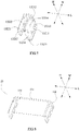
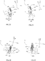
- each of the mating terminals 14 may comprise: two elastic sheets 141 disposed facing each other in the length direction L; and a connection sheet 142.
- Each of the elastic sheets 141 may have: a body portion 1411; and an elastic contact portion 1412 protruding from the body portion 1411 in the height direction H.
- the connection sheet 142 may have: a first connecting portion 1421 extending in the height direction H; and a second connecting portion 1422 extending in the length direction L.
- the first connecting portion 1421 of the connection sheet 142 is fixed between the body portions 1411 of the two elastic sheets 141, the second connecting portion 1422 is positioned outside the two elastic sheets 141 in the length direction L.
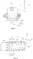
- the elastic contact portions 1412 of the two elastic sheets 141 of the mating terminal 14 directly clamp the second contact segment 1322 of the corresponding conductive connection portion 132 of the conductive connection structure 13.
- the conductive connection portion 132 of the conductive connection structure 13 is firmly fixed between the two elastic sheets 141 of the corresponding mating terminal 14, thereby improving the connection reliability between the conductive connection structure 13 and the mating terminal 14.
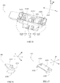
- the base 121 may have a first latching portion 1214 disposed on the assembling portion 1212.
- the protective shell 143 of the mating terminal 14 may further have a second latching portion 1434 latched with the first latching portion 1213 of the base 121 of the pedestal 12 (such as a concave-convex fit) so as to be fixed to the pedestal 12.
- the first latching portion 1214 may be a protrusion
- the second latching portion 1434 may be a through-hole structure
- the first latching portion 1214 may be a through-hole structure
- the second latching portion 1434 may be a protrusion.
- the pedestal 12 may further comprise a mounting seat 122 fixedly mounting the base 121.
- the mounting seat 122 of the pedestal 12 and the box of the battery product may be different components, and the pedestal 12 is fixed to the box via the mounting seat 122.
- the mounting seat 122 may also be one of side walls of the box of the battery product.
- the mounting seat 122 may have: a second bottom plate portion 1221; and a mounting portion 1222 protruding from the second bottom plate portion 1221 in the height direction H.
- the two side plate portions 1213 of the base 121 are positioned in the mounting portion 1222 of the mounting seat 122, and the upper cover 11 is fixedly connected to the mounting portion 1222 of the mounting seat 122.
Landscapes
- Chemical & Material Sciences (AREA)
- Chemical Kinetics & Catalysis (AREA)
- Electrochemistry (AREA)
- General Chemical & Material Sciences (AREA)
- Coupling Device And Connection With Printed Circuit (AREA)
- Battery Mounting, Suspending (AREA)
- Connection Of Batteries Or Terminals (AREA)
- Details Of Connecting Devices For Male And Female Coupling (AREA)
Claims (10)
- Multifunktions-Hochspannungsverbinder (1), aufweisend:eine obere Abdeckung (11);einen mit der oberen Abdeckung (11) zusammengebauten Sockel (12);eine leitfähige Verbindungskonstruktion (13), die fest an der oberen Abdeckung (11) angebracht ist;zwei Gegenklemmen (14); undeine Kabelbaumanordnung (15), die fest an dem Sockel (12) angebracht ist,wobeijede der zwei Gegenklemmen (14) zwei elastische Flächengebilde (141), die einander in einer Längenrichtung (L) gegenüberliegend angeordnet sind, undein Verbindungsflächengebilde (142) beinhaltet;jedes der zwei elastischen Flächengebilde (141) ein Körperstück (1411) und einen elastischen Kontaktteil (1412), der in einer Höhenrichtung (H) aus dem Körperstück (1411) vorsteht, aufweist;das Verbindungsflächengebilde (142) einen ersten Verbindungsteil (1421), der sich in der Höhenrichtung (H) erstreckt, und einen zweiten Verbindungsteil (1422), der sich in der Längenrichtung (L) erstreckt, aufweist;der erste Verbindungsteil (1421) des Verbindungsflächengebildes (142) zwischen den Körperstücken (1411) der zwei elastischen Flächengebilde (141) befestigt ist, der zweite Verbindungsteil (1422) in der Längenrichtung (L) außerhalb der zwei elastischen Flächengebilde (141) positioniert ist;die zwei Gegenklemmen (14) in der Längenrichtung (L) voneinander beabstandet sind und die Gegenklemmen (14) jeweils fest an dem Sockel (12) angebracht sind, die elastischen Kontaktteile (1412) der zwei elastischen Flächengebilde (141) jeder Gegenklemme (14) zum Festklemmen der leitfähigen Verbindungskonstruktion (13) verwendet werden;der zweite Verbindungsteil (1422) von einer der Gegenklemmen (14) von dem ersten Verbindungsteil (1421) der einen der Gegenklemmen (14) in der Längenrichtung (L) beabstandet ist und das Verbindungsflächengebilde (142) der einen der Gegenklemmen (14) ferner einen dritten Verbindungsteil (1423) aufweist, der zwischen dem ersten Verbindungsteil (1421) und dem zweiten Verbindungsteil (1422) der einen der Gegenklemmen (14) positioniert ist, und der dritte Verbindungsteil (1423) mit dem ersten Verbindungsteil (1421) unddem zweiten Verbindungsteil (1422) der einen der Gegenklemmen (14) verbunden ist;der zweite Verbindungsteil (1422) des Verbindungsflächengebildes (142) der anderen der Gegenklemmen (14) direkt mit dem ersten Verbindungsteil (1421) der anderen der Gegenklemmen (14) verbunden ist,dadurch gekennzeichnet, dassdie obere Abdeckung (11) mit einer abgeschrägten Anschlusskonstruktion ausgebildet ist und der Sockel (12) mit einer abgeschrägten Anschlusskonstruktion ausgebildet ist,wobei der Sockel (12) eine Basis (121) und einen fest auf der Basis (121) angebrachten Anbringungssitz (122) beinhaltet und der Anbringungssitz (122) einen zweiten Bodenplattenteil (1221) und einen von dem zweiten Bodenplattenteil (1221) in der Höhenrichtung (H) vorstehenden Anbringungsteil (1222) beinhaltet,wobei in der abgeschrägten Anschlusskonstruktion des Sockels (12) ein Ende des Anbringungsteils (1222) in der Längenrichtung (L) in der Längenrichtung (L) höher ist als das andere Ende des Anbringungsteils (1222),die Kabelbaumanordnung (15) über ein Durchgangsloch in der Längenrichtung (L) durch das eine Ende des Anbringungsteils (1222) verläuft,das Durchgangsloch dem einen Ende des Anbringungsteils (1222) in der Längenrichtung (L) bereitgestellt ist und die Kabelbaumanordnung (15) direkt mit dem zweiten Verbindungsteil (1422) der einen der Gegenklemmen (14) verbunden ist.
- Multifunktions-Hochspannungsverbinder (1) nach Anspruch 1, wobei der elastische Kontaktteil (1412) von jedem elastischen Flächengebilde (141) Folgendes aufweist: ein erstes Erstreckungssegment (14121), das mit dem Körperstück (1411) verbunden ist und sich in der Höhenrichtung (H) schräg zu dem anderen elastischen Flächengebilde (141) hin erstreckt; und ein zweites Erstreckungssegment (14122), das mit dem ersten Erstreckungssegment (14121) verbunden ist und sich in der Höhenrichtung (H) schräg von dem anderen elastischen Flächengebilde (141) weg erstreckt.
- Multifunktions-Hochspannungsverbinder (1) nach Anspruch 1, wobei der elastische Kontaktteil (1412) jedes elastischen Flächengebildes (141) als zahlenmäßiges Mehrfaches bereitgestellt ist, wobei die mehreren elastischen Kontaktteile (1412) in einer Breitenrichtung (W) voneinander beabstandet sind.
- Multifunktions-Hochspannungsverbinder (1) nach Anspruch 1, wobeidie Gegenklemme (14) eine Schutzhülse (143) mit zwei ersten Seitenwänden (1431), die einander in der Längenrichtung (L) gegenüberliegend angeordnet sind, beinhaltet;der elastische Kontaktteil (1412) jedes elastischen Flächengebildes (141) zwischen den zwei ersten Seitenwänden (1431) der Schutzhülse (143) positioniert ist und elastisch gegen die entsprechende erste Seitenwand (1431) drückt, um an der Schutzhülse (143) befestigt zu sein.
- Multifunktions-Hochspannungsverbinder (1) nach Anspruch 4, wobeidie Schutzhülse (143) ferner Folgendes aufweist: zwei obere Wände (1433), die in der Längenrichtung (L) voneinander beabstandet sind, wobei die oberen Wände (1433) jeweils entsprechend mit einer der ersten Seitenwände (1431) verbunden sind und sich in der Längenrichtung (L) zu der anderen der ersten Seitenwände (1431) erstrecken;ein oberes Ende des elastischen Kontaktteils (1412) des elastischen Flächengebildes (141), das von dem Hauptkörperstück (1411) entfernt ist, von unter der oberen Wand (1433) der Schutzhülse (143) elastisch gegen die obere Wand (1433) drückt.
- Multifunktions-Hochspannungsverbinder (1) nach einem der Ansprüche 1 bis 5, wobei
die zwei Gegenklemmen (14) an der Basis (121) angebracht sind. - Multifunktions-Hochspannungsverbinder (1) nach einem der Ansprüche 1 bis 5, wobei der Anbringungsteil (1222) mit der oberen Abdeckung (11) verbunden ist.
- Multifunktions-Hochspannungsverbinder (1) nach Anspruch 1 bis 7, wobei die Kabelbaumanordnung (15) eine Verbindungsklemme (151) und ein mit der Verbindungsklemme (151) verbundenes Kabel (152) beinhaltet, die Verbindungsklemme (151) in dem Sockel (12) positioniert ist und mit der Gegenklemme (14) verbunden ist und der Draht (152) sich durch das Durchgangsloch aus dem Sockel (12) herauserstreckt.
- Multifunktions-Hochspannungsverbinder (1) nach Anspruch 6 oder 8, wobei die Basis (121) Folgendes beinhaltet: einen ersten Bodenplattenteil (1211); zwei Montageteile (1212), die in der Längenrichtung (L) voneinander beabstandet sind und von dem ersten Bodenplattenteil (1211) vorstehen;die zwei Montageteile (1212) zwischen dem ersten Endteil und dem zweiten Endteil positioniert sind;die zwei Gegenklemmen (14) jeweilig mit den zwei Montageteilen (1212) befestigt sind.
- Batterieprodukt, das eine Batterieanordnung und ein Gehäuse aufweist, wobei das Batterieprodukt den Multifunktions-Hochspannungsverbinder (1) nach einem der Anschlüsse 1 bis 9 aufweist, der Sockel (12) des Multifunktions-Hochspannungsverbinders (1) fest an dem Gehäuse angebracht ist, die Batterieanordnung direkt mit der anderen der Gegenklemmen (14) verbunden ist.
Applications Claiming Priority (1)
| Application Number | Priority Date | Filing Date | Title |
|---|---|---|---|
| CN201821314004.7U CN208690572U (zh) | 2018-08-15 | 2018-08-15 | 插接端子、多功能高压连接器及电池产品 |
Publications (2)
| Publication Number | Publication Date |
|---|---|
| EP3611802A1 EP3611802A1 (de) | 2020-02-19 |
| EP3611802B1 true EP3611802B1 (de) | 2023-01-11 |
Family
ID=65885174
Family Applications (1)
| Application Number | Title | Priority Date | Filing Date |
|---|---|---|---|
| EP19188026.9A Active EP3611802B1 (de) | 2018-08-15 | 2019-07-24 | Multifunktionaler hochspannungsverbinder und batterieprodukt |
Country Status (4)
| Country | Link |
|---|---|
| US (1) | US10777930B2 (de) |
| EP (1) | EP3611802B1 (de) |
| CN (1) | CN208690572U (de) |
| PL (1) | PL3611802T3 (de) |
Families Citing this family (8)
| Publication number | Priority date | Publication date | Assignee | Title |
|---|---|---|---|---|
| CN208690601U (zh) * | 2018-08-15 | 2019-04-02 | 宁德时代新能源科技股份有限公司 | 导电连接结构、多功能高压连接器及电池产品 |
| CN208690572U (zh) * | 2018-08-15 | 2019-04-02 | 宁德时代新能源科技股份有限公司 | 插接端子、多功能高压连接器及电池产品 |
| CN208508146U (zh) * | 2018-08-15 | 2019-02-15 | 宁德时代新能源科技股份有限公司 | 多功能高压连接器及电池产品 |
| CN208955294U (zh) * | 2018-11-08 | 2019-06-07 | 宁德时代新能源科技股份有限公司 | 多功能高压连接器 |
| CN111668633B (zh) * | 2020-05-19 | 2024-12-17 | 江西巴斯巴新能源技术有限公司 | 一种大电流连接结构 |
| CN113346265B (zh) * | 2021-06-07 | 2023-03-10 | 江苏开云通讯科技有限公司 | 一种电连接器结构及其组装方法 |
| CN114976416B (zh) * | 2022-06-08 | 2024-05-31 | 一汽解放汽车有限公司 | 一种换电系统及车辆 |
| TWI805401B (zh) * | 2022-06-09 | 2023-06-11 | 貝爾威勒電子股份有限公司 | 具有可替換保險絲的匯流排連接器 |
Family Cites Families (11)
| Publication number | Priority date | Publication date | Assignee | Title |
|---|---|---|---|---|
| US2009A (en) * | 1841-03-18 | Improvement in machines for boring war-rockets | ||
| US8242874B2 (en) * | 2005-08-23 | 2012-08-14 | Lear Corporation | Electrical connector housing |
| EP2048746B1 (de) * | 2007-08-13 | 2016-10-05 | Tyco Electronics Nederland B.V. | Stromschienenanschlusssystem |
| US9099814B2 (en) * | 2013-07-16 | 2015-08-04 | Delphi Technologies, Inc. | Shielded electrical header assembly |
| US9831482B2 (en) * | 2013-09-06 | 2017-11-28 | Johnson Controls Technology Company | Battery module lid system and method |
| CN204304143U (zh) * | 2014-12-02 | 2015-04-29 | 苏州华旃航天电器有限公司 | 一种能够热插拔的保险管组件及连接器 |
| RS61754B1 (sr) * | 2015-03-12 | 2021-05-31 | Aees Inc | Sklop priključne stezaljke niskog profila |
| CN206947673U (zh) * | 2017-06-27 | 2018-01-30 | 东莞能连电子科技有限公司 | 一种新型手动维护开关 |
| CN208690601U (zh) * | 2018-08-15 | 2019-04-02 | 宁德时代新能源科技股份有限公司 | 导电连接结构、多功能高压连接器及电池产品 |
| CN208690572U (zh) * | 2018-08-15 | 2019-04-02 | 宁德时代新能源科技股份有限公司 | 插接端子、多功能高压连接器及电池产品 |
| CN208508146U (zh) * | 2018-08-15 | 2019-02-15 | 宁德时代新能源科技股份有限公司 | 多功能高压连接器及电池产品 |
-
2018
- 2018-08-15 CN CN201821314004.7U patent/CN208690572U/zh active Active
-
2019
- 2019-07-24 EP EP19188026.9A patent/EP3611802B1/de active Active
- 2019-07-24 PL PL19188026.9T patent/PL3611802T3/pl unknown
- 2019-08-14 US US16/540,965 patent/US10777930B2/en active Active
Also Published As
| Publication number | Publication date |
|---|---|
| PL3611802T3 (pl) | 2023-03-20 |
| EP3611802A1 (de) | 2020-02-19 |
| US20200059031A1 (en) | 2020-02-20 |
| US10777930B2 (en) | 2020-09-15 |
| CN208690572U (zh) | 2019-04-02 |
Similar Documents
| Publication | Publication Date | Title |
|---|---|---|
| EP3611802B1 (de) | Multifunktionaler hochspannungsverbinder und batterieprodukt | |
| US11990694B2 (en) | Multifunctional high-voltage connector and battery product | |
| EP3611751B1 (de) | Leitfähige verbindungsstruktur, multifunktioneller hochspannungsverbinder und batterieprodukt | |
| RU2006133325A (ru) | Компоновочный блок колпачка унифицированного типа, содержащий плату защитной схемы, и вторичный аккумулятор, содержащий его | |
| JP2005185032A (ja) | 電気接続箱 | |
| US10770700B2 (en) | Battery pack | |
| EP3651279B1 (de) | Multifunktionaler hochspannungsverbinder und batterieprodukt | |
| WO2016082715A1 (zh) | 一种时间继电器插座 | |
| JP6554038B2 (ja) | 蓄電装置 | |
| EP3896794B1 (de) | Verbinder | |
| CN215183842U (zh) | 一种接触-熔断组合电器、配电盒、电池总成及车辆 | |
| US11476060B1 (en) | Manual service disconnect for in-vehicle electric current | |
| JP7234847B2 (ja) | 電子モジュール | |
| CN208507617U (zh) | 手动维护开关 | |
| CN220065609U (zh) | 一种线束保险丝 | |
| CN222995240U (zh) | 一种电容器上盖组件及电容器 | |
| CN220291250U (zh) | 一种新能源充电接插件 | |
| CN221041790U (zh) | 一种高压屏蔽连接器 | |
| CN222655542U (zh) | 电器盒及车辆 | |
| JP2025168659A (ja) | 電力伝送構成要素および電気接続アセンブリ | |
| CN121922917A (zh) | 一种高压插座、高压连接器、电池包和用电装置 | |
| KR20250157980A (ko) | 전기 연결 제품 | |
| CN120749367A (zh) | 电池包正极断路单元 | |
| JP2025168661A (ja) | 電気接続アセンブリおよび電気接続製品 | |
| CN116683097A (zh) | 电池盖板组件及电池 |
Legal Events
| Date | Code | Title | Description |
|---|---|---|---|
| PUAI | Public reference made under article 153(3) epc to a published international application that has entered the european phase |
Free format text: ORIGINAL CODE: 0009012 |
|
| STAA | Information on the status of an ep patent application or granted ep patent |
Free format text: STATUS: REQUEST FOR EXAMINATION WAS MADE |
|
| 17P | Request for examination filed |
Effective date: 20190724 |
|
| AK | Designated contracting states |
Kind code of ref document: A1 Designated state(s): AL AT BE BG CH CY CZ DE DK EE ES FI FR GB GR HR HU IE IS IT LI LT LU LV MC MK MT NL NO PL PT RO RS SE SI SK SM TR |
|
| AX | Request for extension of the european patent |
Extension state: BA ME |
|
| STAA | Information on the status of an ep patent application or granted ep patent |
Free format text: STATUS: EXAMINATION IS IN PROGRESS |
|
| 17Q | First examination report despatched |
Effective date: 20210720 |
|
| REG | Reference to a national code |
Ref country code: DE Ref legal event code: R079 Ref document number: 602019024211 Country of ref document: DE Free format text: PREVIOUS MAIN CLASS: H01R0011280000 Ipc: H01M0050502000 |
|
| GRAP | Despatch of communication of intention to grant a patent |
Free format text: ORIGINAL CODE: EPIDOSNIGR1 |
|
| STAA | Information on the status of an ep patent application or granted ep patent |
Free format text: STATUS: GRANT OF PATENT IS INTENDED |
|
| RIC1 | Information provided on ipc code assigned before grant |
Ipc: H01M 50/204 20210101ALN20221005BHEP Ipc: H01R 11/28 20060101ALI20221005BHEP Ipc: H01R 13/11 20060101ALI20221005BHEP Ipc: H01M 50/502 20210101AFI20221005BHEP |
|
| INTG | Intention to grant announced |
Effective date: 20221024 |
|
| GRAS | Grant fee paid |
Free format text: ORIGINAL CODE: EPIDOSNIGR3 |
|
| GRAA | (expected) grant |
Free format text: ORIGINAL CODE: 0009210 |
|
| STAA | Information on the status of an ep patent application or granted ep patent |
Free format text: STATUS: THE PATENT HAS BEEN GRANTED |
|
| AK | Designated contracting states |
Kind code of ref document: B1 Designated state(s): AL AT BE BG CH CY CZ DE DK EE ES FI FR GB GR HR HU IE IS IT LI LT LU LV MC MK MT NL NO PL PT RO RS SE SI SK SM TR |
|
| REG | Reference to a national code |
Ref country code: GB Ref legal event code: FG4D |
|
| REG | Reference to a national code |
Ref country code: CH Ref legal event code: EP |
|
| REG | Reference to a national code |
Ref country code: DE Ref legal event code: R096 Ref document number: 602019024211 Country of ref document: DE |
|
| REG | Reference to a national code |
Ref country code: IE Ref legal event code: FG4D |
|
| REG | Reference to a national code |
Ref country code: AT Ref legal event code: REF Ref document number: 1543966 Country of ref document: AT Kind code of ref document: T Effective date: 20230215 |
|
| REG | Reference to a national code |
Ref country code: LT Ref legal event code: MG9D |
|
| REG | Reference to a national code |
Ref country code: NL Ref legal event code: MP Effective date: 20230111 |
|
| REG | Reference to a national code |
Ref country code: AT Ref legal event code: MK05 Ref document number: 1543966 Country of ref document: AT Kind code of ref document: T Effective date: 20230111 |
|
| P01 | Opt-out of the competence of the unified patent court (upc) registered |
Effective date: 20230516 |
|
| PG25 | Lapsed in a contracting state [announced via postgrant information from national office to epo] |
Ref country code: NL Free format text: LAPSE BECAUSE OF FAILURE TO SUBMIT A TRANSLATION OF THE DESCRIPTION OR TO PAY THE FEE WITHIN THE PRESCRIBED TIME-LIMIT Effective date: 20230111 |
|
| PG25 | Lapsed in a contracting state [announced via postgrant information from national office to epo] |
Ref country code: RS Free format text: LAPSE BECAUSE OF FAILURE TO SUBMIT A TRANSLATION OF THE DESCRIPTION OR TO PAY THE FEE WITHIN THE PRESCRIBED TIME-LIMIT Effective date: 20230111 Ref country code: PT Free format text: LAPSE BECAUSE OF FAILURE TO SUBMIT A TRANSLATION OF THE DESCRIPTION OR TO PAY THE FEE WITHIN THE PRESCRIBED TIME-LIMIT Effective date: 20230511 Ref country code: NO Free format text: LAPSE BECAUSE OF FAILURE TO SUBMIT A TRANSLATION OF THE DESCRIPTION OR TO PAY THE FEE WITHIN THE PRESCRIBED TIME-LIMIT Effective date: 20230411 Ref country code: LV Free format text: LAPSE BECAUSE OF FAILURE TO SUBMIT A TRANSLATION OF THE DESCRIPTION OR TO PAY THE FEE WITHIN THE PRESCRIBED TIME-LIMIT Effective date: 20230111 Ref country code: LT Free format text: LAPSE BECAUSE OF FAILURE TO SUBMIT A TRANSLATION OF THE DESCRIPTION OR TO PAY THE FEE WITHIN THE PRESCRIBED TIME-LIMIT Effective date: 20230111 Ref country code: HR Free format text: LAPSE BECAUSE OF FAILURE TO SUBMIT A TRANSLATION OF THE DESCRIPTION OR TO PAY THE FEE WITHIN THE PRESCRIBED TIME-LIMIT Effective date: 20230111 Ref country code: ES Free format text: LAPSE BECAUSE OF FAILURE TO SUBMIT A TRANSLATION OF THE DESCRIPTION OR TO PAY THE FEE WITHIN THE PRESCRIBED TIME-LIMIT Effective date: 20230111 Ref country code: AT Free format text: LAPSE BECAUSE OF FAILURE TO SUBMIT A TRANSLATION OF THE DESCRIPTION OR TO PAY THE FEE WITHIN THE PRESCRIBED TIME-LIMIT Effective date: 20230111 |
|
| PG25 | Lapsed in a contracting state [announced via postgrant information from national office to epo] |
Ref country code: SE Free format text: LAPSE BECAUSE OF FAILURE TO SUBMIT A TRANSLATION OF THE DESCRIPTION OR TO PAY THE FEE WITHIN THE PRESCRIBED TIME-LIMIT Effective date: 20230111 Ref country code: IS Free format text: LAPSE BECAUSE OF FAILURE TO SUBMIT A TRANSLATION OF THE DESCRIPTION OR TO PAY THE FEE WITHIN THE PRESCRIBED TIME-LIMIT Effective date: 20230511 Ref country code: GR Free format text: LAPSE BECAUSE OF FAILURE TO SUBMIT A TRANSLATION OF THE DESCRIPTION OR TO PAY THE FEE WITHIN THE PRESCRIBED TIME-LIMIT Effective date: 20230412 Ref country code: FI Free format text: LAPSE BECAUSE OF FAILURE TO SUBMIT A TRANSLATION OF THE DESCRIPTION OR TO PAY THE FEE WITHIN THE PRESCRIBED TIME-LIMIT Effective date: 20230111 |
|
| REG | Reference to a national code |
Ref country code: DE Ref legal event code: R097 Ref document number: 602019024211 Country of ref document: DE |
|
| PG25 | Lapsed in a contracting state [announced via postgrant information from national office to epo] |
Ref country code: SM Free format text: LAPSE BECAUSE OF FAILURE TO SUBMIT A TRANSLATION OF THE DESCRIPTION OR TO PAY THE FEE WITHIN THE PRESCRIBED TIME-LIMIT Effective date: 20230111 Ref country code: RO Free format text: LAPSE BECAUSE OF FAILURE TO SUBMIT A TRANSLATION OF THE DESCRIPTION OR TO PAY THE FEE WITHIN THE PRESCRIBED TIME-LIMIT Effective date: 20230111 Ref country code: EE Free format text: LAPSE BECAUSE OF FAILURE TO SUBMIT A TRANSLATION OF THE DESCRIPTION OR TO PAY THE FEE WITHIN THE PRESCRIBED TIME-LIMIT Effective date: 20230111 Ref country code: DK Free format text: LAPSE BECAUSE OF FAILURE TO SUBMIT A TRANSLATION OF THE DESCRIPTION OR TO PAY THE FEE WITHIN THE PRESCRIBED TIME-LIMIT Effective date: 20230111 Ref country code: CZ Free format text: LAPSE BECAUSE OF FAILURE TO SUBMIT A TRANSLATION OF THE DESCRIPTION OR TO PAY THE FEE WITHIN THE PRESCRIBED TIME-LIMIT Effective date: 20230111 |
|
| PLBE | No opposition filed within time limit |
Free format text: ORIGINAL CODE: 0009261 |
|
| STAA | Information on the status of an ep patent application or granted ep patent |
Free format text: STATUS: NO OPPOSITION FILED WITHIN TIME LIMIT |
|
| PG25 | Lapsed in a contracting state [announced via postgrant information from national office to epo] |
Ref country code: SK Free format text: LAPSE BECAUSE OF FAILURE TO SUBMIT A TRANSLATION OF THE DESCRIPTION OR TO PAY THE FEE WITHIN THE PRESCRIBED TIME-LIMIT Effective date: 20230111 |
|
| 26N | No opposition filed |
Effective date: 20231012 |
|
| PG25 | Lapsed in a contracting state [announced via postgrant information from national office to epo] |
Ref country code: SI Free format text: LAPSE BECAUSE OF FAILURE TO SUBMIT A TRANSLATION OF THE DESCRIPTION OR TO PAY THE FEE WITHIN THE PRESCRIBED TIME-LIMIT Effective date: 20230111 |
|
| PG25 | Lapsed in a contracting state [announced via postgrant information from national office to epo] |
Ref country code: MC Free format text: LAPSE BECAUSE OF FAILURE TO SUBMIT A TRANSLATION OF THE DESCRIPTION OR TO PAY THE FEE WITHIN THE PRESCRIBED TIME-LIMIT Effective date: 20230111 |
|
| PG25 | Lapsed in a contracting state [announced via postgrant information from national office to epo] |
Ref country code: MC Free format text: LAPSE BECAUSE OF FAILURE TO SUBMIT A TRANSLATION OF THE DESCRIPTION OR TO PAY THE FEE WITHIN THE PRESCRIBED TIME-LIMIT Effective date: 20230111 |
|
| REG | Reference to a national code |
Ref country code: CH Ref legal event code: PL |
|
| REG | Reference to a national code |
Ref country code: BE Ref legal event code: MM Effective date: 20230731 |
|
| PG25 | Lapsed in a contracting state [announced via postgrant information from national office to epo] |
Ref country code: LU Free format text: LAPSE BECAUSE OF NON-PAYMENT OF DUE FEES Effective date: 20230724 |
|
| PG25 | Lapsed in a contracting state [announced via postgrant information from national office to epo] |
Ref country code: LU Free format text: LAPSE BECAUSE OF NON-PAYMENT OF DUE FEES Effective date: 20230724 |
|
| REG | Reference to a national code |
Ref country code: IE Ref legal event code: MM4A |
|
| PG25 | Lapsed in a contracting state [announced via postgrant information from national office to epo] |
Ref country code: CH Free format text: LAPSE BECAUSE OF NON-PAYMENT OF DUE FEES Effective date: 20230731 |
|
| PG25 | Lapsed in a contracting state [announced via postgrant information from national office to epo] |
Ref country code: IT Free format text: LAPSE BECAUSE OF FAILURE TO SUBMIT A TRANSLATION OF THE DESCRIPTION OR TO PAY THE FEE WITHIN THE PRESCRIBED TIME-LIMIT Effective date: 20230111 Ref country code: BE Free format text: LAPSE BECAUSE OF NON-PAYMENT OF DUE FEES Effective date: 20230731 |
|
| PG25 | Lapsed in a contracting state [announced via postgrant information from national office to epo] |
Ref country code: IE Free format text: LAPSE BECAUSE OF NON-PAYMENT OF DUE FEES Effective date: 20230724 |
|
| PG25 | Lapsed in a contracting state [announced via postgrant information from national office to epo] |
Ref country code: IE Free format text: LAPSE BECAUSE OF NON-PAYMENT OF DUE FEES Effective date: 20230724 |
|
| REG | Reference to a national code |
Ref country code: DE Ref legal event code: R081 Ref document number: 602019024211 Country of ref document: DE Owner name: CONTEMPORARY AMPEREX TECHNOLOGY (HONG KONG) LI, HK Free format text: FORMER OWNER: CONTEMPORARY AMPEREX TECHNOLOGY CO., LIMITED, NINGDE CITY, FUJIAN, CN |
|
| REG | Reference to a national code |
Ref country code: GB Ref legal event code: 732E Free format text: REGISTERED BETWEEN 20240815 AND 20240821 |
|
| PG25 | Lapsed in a contracting state [announced via postgrant information from national office to epo] |
Ref country code: BG Free format text: LAPSE BECAUSE OF FAILURE TO SUBMIT A TRANSLATION OF THE DESCRIPTION OR TO PAY THE FEE WITHIN THE PRESCRIBED TIME-LIMIT Effective date: 20230111 |
|
| PG25 | Lapsed in a contracting state [announced via postgrant information from national office to epo] |
Ref country code: BG Free format text: LAPSE BECAUSE OF FAILURE TO SUBMIT A TRANSLATION OF THE DESCRIPTION OR TO PAY THE FEE WITHIN THE PRESCRIBED TIME-LIMIT Effective date: 20230111 |
|
| PGFP | Annual fee paid to national office [announced via postgrant information from national office to epo] |
Ref country code: PL Payment date: 20250515 Year of fee payment: 7 |
|
| PGFP | Annual fee paid to national office [announced via postgrant information from national office to epo] |
Ref country code: GB Payment date: 20250605 Year of fee payment: 7 |
|
| PGFP | Annual fee paid to national office [announced via postgrant information from national office to epo] |
Ref country code: FR Payment date: 20250610 Year of fee payment: 7 |
|
| PG25 | Lapsed in a contracting state [announced via postgrant information from national office to epo] |
Ref country code: CY Free format text: LAPSE BECAUSE OF FAILURE TO SUBMIT A TRANSLATION OF THE DESCRIPTION OR TO PAY THE FEE WITHIN THE PRESCRIBED TIME-LIMIT; INVALID AB INITIO Effective date: 20190724 |
|
| PG25 | Lapsed in a contracting state [announced via postgrant information from national office to epo] |
Ref country code: HU Free format text: LAPSE BECAUSE OF FAILURE TO SUBMIT A TRANSLATION OF THE DESCRIPTION OR TO PAY THE FEE WITHIN THE PRESCRIBED TIME-LIMIT; INVALID AB INITIO Effective date: 20190724 |
|
| PGFP | Annual fee paid to national office [announced via postgrant information from national office to epo] |
Ref country code: DE Payment date: 20250528 Year of fee payment: 7 |
|
| PG25 | Lapsed in a contracting state [announced via postgrant information from national office to epo] |
Ref country code: TR Free format text: LAPSE BECAUSE OF FAILURE TO SUBMIT A TRANSLATION OF THE DESCRIPTION OR TO PAY THE FEE WITHIN THE PRESCRIBED TIME-LIMIT Effective date: 20230111 |