EP3611806B1 - Adaptateur et système à vide - Google Patents
Adaptateur et système à vide Download PDFInfo
- Publication number
- EP3611806B1 EP3611806B1 EP19214555.5A EP19214555A EP3611806B1 EP 3611806 B1 EP3611806 B1 EP 3611806B1 EP 19214555 A EP19214555 A EP 19214555A EP 3611806 B1 EP3611806 B1 EP 3611806B1
- Authority
- EP
- European Patent Office
- Prior art keywords
- module
- connector
- base element
- primary
- connectors
- Prior art date
- Legal status (The legal status is an assumption and is not a legal conclusion. Google has not performed a legal analysis and makes no representation as to the accuracy of the status listed.)
- Active
Links
Images
Classifications
-
- H—ELECTRICITY
- H01—ELECTRIC ELEMENTS
- H01R—ELECTRICALLY-CONDUCTIVE CONNECTIONS; STRUCTURAL ASSOCIATIONS OF A PLURALITY OF MUTUALLY-INSULATED ELECTRICAL CONNECTING ELEMENTS; COUPLING DEVICES; CURRENT COLLECTORS
- H01R13/00—Details of coupling devices of the kinds covered by groups H01R12/70 or H01R24/00 - H01R33/00
- H01R13/44—Means for preventing access to live contacts
- H01R13/447—Shutter or cover plate
-
- H—ELECTRICITY
- H01—ELECTRIC ELEMENTS
- H01R—ELECTRICALLY-CONDUCTIVE CONNECTIONS; STRUCTURAL ASSOCIATIONS OF A PLURALITY OF MUTUALLY-INSULATED ELECTRICAL CONNECTING ELEMENTS; COUPLING DEVICES; CURRENT COLLECTORS
- H01R31/00—Coupling parts supported only by co-operation with counterpart
- H01R31/06—Intermediate parts for linking two coupling parts, e.g. adapter
-
- F—MECHANICAL ENGINEERING; LIGHTING; HEATING; WEAPONS; BLASTING
- F04—POSITIVE - DISPLACEMENT MACHINES FOR LIQUIDS; PUMPS FOR LIQUIDS OR ELASTIC FLUIDS
- F04B—POSITIVE-DISPLACEMENT MACHINES FOR LIQUIDS; PUMPS
- F04B45/00—Pumps or pumping installations having flexible working members and specially adapted for elastic fluids
- F04B45/04—Pumps or pumping installations having flexible working members and specially adapted for elastic fluids having plate-like flexible members, e.g. diaphragms
- F04B45/047—Pumps having electric drive
-
- H—ELECTRICITY
- H01—ELECTRIC ELEMENTS
- H01R—ELECTRICALLY-CONDUCTIVE CONNECTIONS; STRUCTURAL ASSOCIATIONS OF A PLURALITY OF MUTUALLY-INSULATED ELECTRICAL CONNECTING ELEMENTS; COUPLING DEVICES; CURRENT COLLECTORS
- H01R13/00—Details of coupling devices of the kinds covered by groups H01R12/70 or H01R24/00 - H01R33/00
- H01R13/64—Means for preventing incorrect coupling
Definitions
- the present invention relates in principle to an adapter for the information technology connection of a vacuum device to a functional element for the vacuum device.
- the invention relates to a vacuum system with a vacuum device, functional element and adapter.
- Vacuum devices are often optimized for certain properties, e.g. in terms of mechanics, attachment, size and manufacturing costs, in order to be able to be used in the best possible way in the respective applications. However, this is usually accompanied by the restriction or waiver of certain functions, such as connection options for accessories, communication interfaces, control inputs/outputs, separate inputs for power supply, operating and display elements, etc.
- connection options for accessories e.g. in terms of mechanics, attachment, size and manufacturing costs
- connection options for accessories e.g. in terms of mechanics, attachment, size and manufacturing costs
- connection options for accessories e.g. in terms of mechanics, attachment, size and manufacturing costs
- connection options for accessories e.g. in terms of mechanics, attachment, size and manufacturing costs
- connection options for accessories e.g. in terms of mechanics, attachment, size and manufacturing costs
- control inputs/outputs e.g. data acquisition via Ethernet for the purpose of condition monitoring or new applications
- accessories e.g. integrated pressure measurement technology
- adapters e.g. to connect an RS485 interface and accessories
- connection components e.g. accessory connections and switches in DC cables
- the adapters are then adapted to an application, ie plug-in direction, cable outlets, positioning of the respective elements, such as connections, controls and labeling, are based on a specific application and can possibly be do not use in other applications.
- adapters for accessories e.g. plug connectors integrated in the DC cable
- cables on adapters exit in different directions due to different mounting orientations of different pumps.
- the EP 3 029 327 A1 discloses a vacuum system with a vacuum device and a functional element.
- the US 8,708,722 B1 discloses a power adapter for USB devices, the power adapter having a base element with a USB connection and an interchangeable head with contacts for plugging into a mains socket, different heads with different types of contacts for different country standards being connectable to the base element.
- an adapter which comprises: a base element, a first and a second primary connector, each for connection to one of the vacuum device and functional element, the primary connectors being connected to one another, a module which is separate from the base element and has the first primary connector and attached to the base member, the base member and the module each having an interconnector which together form an interconnect through which the first primary connector is connected to the second primary connector.
- the intermediate connector and the separate design of the module or the first primary connector enable particular flexibility and a reduction in the number of adapters required.
- this allows different modules to be used as required, with one and the same basic element being able to be used in particular.
- the modules can fundamentally differ in their function or also in their spatial orientation of the first primary connector relative to the intermediate connector.
- this enables the module to be arranged on the base element in different arrangements or with different relative orientations of the first primary connector to the second primary connector.
- connection and “connect” are used here in the sense of an electrical and/or information technology connection.
- a mechanical coupling of two elements, on the other hand, is referred to in particular as “fastening”.
- the adapter forms at least one information technology connection. In principle, the adapter can also form an electrical connection.
- connection between the primary plug connectors is made possible by the intermediate connection or is established in the connected state.
- the Intermediate connectors can be brought together to make the connection, for example at the manufacture of the adapter or by its user.
- the present invention aims in particular to design parts of the adapter in such a way that the overall product can be adapted to the circumstances in the best possible way, if necessary also by the user himself be provided uniform controls.
- these can be oriented or configured differently due to the assembly on the overall system.
- these are always designed the same way, but differ in details or optional functions depending on the device.
- the connector is only used as a signal or analog input, for example.
- Accessories are also supported on some devices and not on others. However, the alternative uses are defined in such a way that no incompatibilities arise.
- an adapter of the present invention should preferably support the maximum set of possible configurations. In a classic design according to the state of the art, this would amount to a device with a fixed assignment of all elements, which can then only be used to a limited extent in other vacuum solutions.
- the module of the adapter is preferably designed in such a way that it can be mounted at different angles and/or in different places on the base element. The assembly can be done at or before delivery and/or by the user.
- the parts of the adapter in particular the intermediate connectors are preferably designed in such a way that no impermissible access to certain parts of the adapter, in particular an interior of the base element and/or, for example, sensitive electronic assemblies, can take place.
- the adapter has a function that goes beyond pure contacting or connection.
- the adapter has the features according to the invention with particular flexibility, in particular spatial flexibility.
- the adapter can include a Profinet gateway, the provision of functions or signals and/or signal conversions derived from the primary connectors to other connectors, whereby in particular the connection of the primary connectors can be retained in order to keep the other functions present on these connectors untouched or at least continue to do so to be usable.
- a supply voltage for a vacuum device in particular a turbomolecular pump
- the supply voltage can then be passed on to the vacuum device via the first primary connector, for example.
- other signals for the function can be derived, converted or interrupted, for example RS485 signals, which are only required for a Profinet gateway function and are not forwarded.
- the invention thus makes it possible in particular to allow as many vacuum devices as possible to benefit from the advantageous function of the adapter.
- the orientation of the vacuum device and functional element can be chosen advantageously by rotating the module or mounting it at a different location or using a different connector (e.g. HD-Sub-26 instead of D-Sub-15). for example, to design cable outlets advantageously, to take into account the given space conditions or to enable assembly in principle.
- the module can be arranged and/or fastened in at least two different spatial configurations on the base element. Accordingly, in particular the spatial arrangement of the first primary connector, which is part of the module, is different. This makes it possible in a simple manner for functional elements with differently arranged plug connectors to be connected to the vacuum device.
- a difference between two possible arrangements of the module can include, for example, a rotation of the first primary connector, preferably by 90° or 180°.
- the difference can also include several turns, for example.
- the axis of rotation of the rotation can preferably be the plug-in axis of the first or second primary connector and/or a connection axis, in particular a plug-in axis, of the intermediate connector or, for example, an axis that runs perpendicular to both plug-in axes.
- a development provides that an assignment of contacts of the first primary connector to contacts of the second primary connector is the same in both arrangements. This can be achieved, for example, by appropriate wiring or, for example, by appropriate programming of a logic element of the base element or of the module. In particular, the assignment is the same for at least some of the contacts of the connector or for all contacts. In particular, the assignment can be the same for several or all possible arrangements of the at least one module.
- the base element and/or the intermediate connector of the base element can be designed to have different modules with a primary connector can be attached to the base element.
- the intermediate connector can thus be used for a wide variety of modules, which are each adapted for different functional elements or vacuum devices or their connections.
- the intermediate connectors on the base element can be designed in such a way that they can be used to connect to functionally different modules.
- a module of the first type for example with a 15-pin D-Sub socket
- a module of the second type for example with a 26-pin HD-Sub socket
- the assembly of a large number of different modules can also be provided.
- the second primary connector retains its function, in particular regardless of which module is connected. This further increases the possible field of application of such an adapter.
- a pure plug adaptation can be implemented by the adapter, for example between D-Sub-15 and HD-Sub-26.
- the module can have a first primary connector with a function that is not provided for in the second primary connector or in the vacuum device or functional element that is connected to the second primary connector.
- the module can have a Profinet connection that can be used, for example, for different drive devices.
- the adapter can therefore generally have functions that the vacuum device or the functional element do not have. The adapter thus enables in particular a connection with old devices and, thanks to the additional functions, their upgrading.
- a computing unit such as a microcontroller
- the base part which, for example, provides a conversion of information between two connectors, in particular the primary connectors.
- the computing unit can thus provide, for example, a bus connection for a vacuum device which—for example because of its age—does not have such a bus connection.
- An adapter set for the information technology connection of a vacuum device to a functional element for the vacuum device can advantageously be provided, the adapter set comprising: a base element with a first intermediate connector and a second primary connector or a second intermediate connector for connection to a module with a second primary connector; a first module, separate from the base, having a first primary connector and an intermediate connector for connection to the first interconnect of the base; and a second module, separate from the base, having a third primary connector and an intermediate connector for connection to the first interconnect of the base.
- the modules can be different, in particular have different primary connectors.
- three or more modules can also be provided.
- one or more modules with intermediate connectors for connection to the second intermediate connector of the base element can also be provided, in particular with different second primary connectors.
- the intermediate connectors are designed as plug connectors.
- connectors in particular the intermediate connectors and/or at least one of the primary connectors, can preferably be designed as a socket or plug.
- the intermediate connection can preferably be designed as a detachable connection. This enables particular flexibility and in particular a repeatable change in the configuration, in particular by a service employee of the manufacturer or by the user himself.
- the module can be detachably attached to the base element, in particular screwed.
- the intermediate connection is designed in such a way that the intermediate connector of the module can be connected to the intermediate connector of the base element when the module is in different orientations.
- the Function of the module or the first primary connector at least partially, in particular fully guaranteed.
- the module can be attached or fastened to the base element in a technically functioning manner, in particular in different orientations and/or at different positions relative to the base element.
- the information technology connection is provided in the different orientations or positions and is established in particular by or when attaching or fastening the module to the base element in the selected orientation or position.
- an arrangement of the first primary connector is fixed relative to the intermediate connector of the module.
- the module is designed as a fixed structure and/or the first primary connector and the intermediate connector of the module are positioned relative to one another and/or connected to one another by a fixed structure, e.g. by a circuit board, in particular not just by a cable.
- a fixed structure e.g. by a circuit board, in particular not just by a cable.
- an arrangement of the second primary connector or of a second intermediate connector upstream of the second primary connector is fixed relative to the first intermediate connector of the base element.
- the relative arrangement and/or connection of the (first) intermediate connector to the second primary connector or the second intermediate connector can preferably be formed by a fixed structure, for example a circuit board, and in particular not by a cable.
- a particular idea of the invention is that the base element and the module or modules can be flexibly connected to one another as fixed units and that different spatial arrangements and/or different functions can be implemented in this way, and in particular with fewer parts than if - as in State of the art - a specific adapter is provided for each desired configuration.
- the base element and/or the module can preferably be designed as a solid body.
- a base element which is essentially cuboid and/or box-shaped is particularly advantageous.
- the base element has a second intermediate connector for connecting a module with a primary connector.
- a further or another module can be connectable to the second intermediate connector.
- the module can be, for example, a module with the second primary connector or a module with a further first primary connector or a third primary connector.
- the second intermediate connector can therefore be provided either for the second primary connector or for a first primary connector.
- the adapter in principle, it is possible for the adapter to offer a number of mounting positions for mounting at least one module on the base element, which can in particular be assigned once, multiple times or completely. Exactly one of several mounting positions can therefore be selected in a suitable position and orientation, but several modules can also be mounted on these several mounting positions, e.g. to provide a variable number of accessory connections.
- primary connectors and/or accessory connection points which include, for example, connectors, LEDs, switches and/or the like
- the second intermediate connector can be covered by a cover.
- the cover can be provided on any intermediate connector in particular in the event that no module is connected to this intermediate connector. If, for example, two intermediate connectors are provided for realizing two possible assembly positions of the module on the base element, the module can be connected to one of the intermediate connectors and the second intermediate connector can be covered by the cover.
- the cover is detachably fastened to the base element. When changing the module from one possible mounting position to another, the cover can also be attached to the previous mounting position of the module, ie cover the corresponding intermediate connector.
- the cover can be designed, for example, as a plate, in particular a dummy plate, and/or can be detachably fastened, in particular screwed, to the base element.
- the cover can preferably have a fastening interface which corresponds to a fastening interface of the module. In this case, the module and the cover are easily interchangeable.
- the module can be arranged and/or fastened optionally on a first side of the base element or on a second side of the base element, preferably opposite the first. This makes it possible in a simple manner for the adapter to be able to be used to connect the vacuum device and functional element in different spatial configurations.
- the adapter can also comprise a second module, which has the second primary connector, with an intermediate connector being provided on the base element and on the second module, which together form a second intermediate connection.
- the connection between the first and the second primary connector takes place in particular via the second intermediate connection.
- the connection is realized via the first and the second intermediate connection, wherein, in particular, further conductors are also provided in the modules and/or the base element.
- At least one of the primary connectors can preferably be designed as a D-Sub connector.
- a module can have one or more primary connectors.
- a primary connector can be designed as a plug or socket, for example.
- a fixed assignment of contacts of its intermediate connector and/or the first primary connector to contacts of the second primary connector and/or possibly a second intermediate connector of the base element is provided in the base element.
- the fixed assignment can be wired and/or the base element can have a logic element for assigning contacts and/or converting information.
- the fixed assignment can also be the same or provided in particular when the module is arranged in at least two different mounting positions or arrangements on the base element.
- the second primary connector can therefore be arranged either directly on the base element or on a module.
- several primary connectors can each be provided on the base element or on the module.
- a vacuum device can be connected to the first primary connector, for example, and at least two additional primary connectors can be provided, each for connecting a functional element.
- a primary connector can be designed for connection to a bus system, for example as a Profinet and/or Ethernet connection.
- a connection for a bus system can be provided in particular in addition to a first and second primary connector.
- the adapter is designed for the transmission of information, analog and/or digital.
- it can be designed to transmit electrical power, in particular a drive power of the vacuum device or generally a power supply of the functional element or vacuum device.
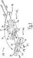
- an adapter 10 is shown in an exploded view. This comprises, in particular, a base element 12, a module 14 and an optional cover 16, which are connected to a functional element (not shown) with the screws shown to form a ready-to-use adapter for the purpose of connecting a vacuum device.
- the module 14 includes a first primary connector 18, which is designed here by way of example as a D-Sub connector.
- the primary connector 18 therefore only allows a connection with a specific orientation of the module 14 relative to the connector to be connected to the vacuum device or the functional element.
- the primary connector 18 is preferably connected to a panel 20 of the module 14 and is releasably attached to the panel 20 by two screws 22 on the base member 12 in particular.
- the base element 12 includes a second primary connector 24, which is also designed here as a D-Sub connector.
- the second primary connector 24 is connected to an intermediate connector 26 of the base element 12, namely by lines (not shown) inside the cuboid body of the base element 12.
- the second primary connector 24 can be provided for connection to a vacuum device, with the first primary connector 18 being provided for connection to a functional element for the vacuum device.
- a reverse configuration is also possible.
- the base element 12 also includes two plug connectors 25, which in particular also form primary plug connectors. At least one of the plug connectors 25 can form a communication and/or bus connection, e.g. a Profinet connection.
- the vacuum device can be integrated into a process control system via the connection, for example.
- a computing unit for example, can be provided in the base part, which defines an interface for the connection.
- the connection can be designed for a vacuum device which itself does not have such a connection or a corresponding interface.
- the adapter 10 can provide such a connection to an older vacuum device.
- the plug connectors 25 could also be arranged on a module that is separate from the base element 12 .
- the module 14 also comprises an intermediate connector 28 which is arranged on the side of the module 14 which faces the intermediate connector 26 and is therefore in 1 is not visible. Upon attachment of module 14 to base member 12 in the configuration illustrated herein, intermediate connectors 26 and 28 are brought together and then form an interconnection between primary connectors 18 and 24.
- the base element 12 also includes a second intermediate connector 30, specifically in this embodiment on the side of the base element 12 opposite or facing away from the first intermediate connector 26. Due to the in 1 selected perspective, the second intermediate connector 30 is not visible.
- the second intermediate connector 30 is designed in particular to correspond to the intermediate connector 26 .
- the module 14 can be selectively connected to the intermediate connector 26 or to the intermediate connector 30 .
- At least two different mounting positions for the module 14 are therefore provided, as indicated by an arrow 32 . Different arrangements of the module 14 or of the first primary connector 18 relative to the second primary connector 24 are thus possible, namely simply by selecting one of the possible assembly positions.
- the interposer 30 is covered by the cover 16 to protect the interposer 30 .
- the cover 16 and the module 14 can be interchanged in their assembly position.
- an intermediate connector or a mounting position for a module can also be provided on another or further side 34 of the base element 12 .
- the intermediate connectors 26 and 28 are designed in such a way that they can be functionally connected in different spatial configurations, that is to say with different relative orientations of the module 14 relative to the base element 12 .
- this embodiment in addition to the in 1 shown orientation of the module 14 another orientation possible, in which the module 14 is rotated 180 ° about the plug-in axis of the first primary connector 18, as it is indicated by the arrow 36.
- the plug-in axis of the first primary connector 18 corresponds here to the connection axis of the intermediate connectors 26 and 28.
- the module 14 or the intermediate connector 28 can also be attached to the intermediate connector 30 or the corresponding side of the base element 12 in different orientations, namely also in different orientations by 180°. A total of four different arrangements of the module 14 on the base element 12 are therefore possible in the embodiment shown.
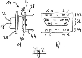
- FIG. 2 illustrates the structure of a module, in particular the module 14 of 1 . while showing Figure 2a the module 14 in a side view.
- the D-sub connector or first primary connector 18 is attached to the board 20 such that its male contacts 36 in Figure 2a to the left and in 1 or are directed outwards in the assembly.
- the plug contacts 36 have extensions 38 which are connected to a circuit board 40 .
- Also connected to the circuit board 40 are a plurality of contacts 42 and 44 associated with the extensions 38 and the plug contacts 36, respectively, in particular by conductors formed on the circuit board 40. In Figure 2a only one contact of a respective row 42 or 44 is visible.
- the contacts 42 and 44 form an intermediate connector 28 of the module 14 and are designed here as pins. They are respectively to be mated with associated contacts 46 and 48 of the interconnector 26 of the base 12 to form an interconnection.
- the contacts 46 and 48 are designed as sockets for the pins.
- the contacts 42 and 44 are arranged such that the interconnection is maintained at various orientations of the module 14 relative to the Base part 12 can be produced. For this purpose, the contacts 42 and 44 on the one hand and 46 and 48 on the other hand are arranged in corresponding rows.
- two orientations of the module 14 are possible, namely firstly by plugging in the in Figure 2a upper row of contacts 42 in the in 1 top row of contacts 46 and the in Figure 2a bottom row 44 into the in 1 lower row 48 and secondly by inserting the in Figure 2a top row 42 into the in 1 lower row 48 and the in Figure 2a bottom row 44 into the in 1 upper row 46.
- FIG. 2b An assignment of the plug contacts 36 or their extensions 38 to the contacts 42, 44 is in Figure 2b illustrated by numbering each contact.
- the male contacts 36 include 15 contacts and the contacts 42 and 44 each include 15 contacts.
- the contacts 36 are assigned to the contacts 42 or 44 with a corresponding number, ie the contact 36.1 is assigned to both the contact 42.1 and the contact 44.1, etc.
- the adapter 10 includes a first primary connector 18 which can be arranged on the base part 12 at two different locations or sides of the base part 12 in two orientations and thus in four different ways. This enables a large number of different alignments that are optimal for the application, especially with regard to the alignment of cable outlets or control elements.
- the module 14 can be mounted in two orientations rotated by 180°, the other side of the base part 12 has a cover 16, here in the form of a blind plate. However, it is also possible to swap the positions of the cover 16 and the module 14.
- the remaining elements of the adapter retain their position in this example, so that there is a selection of possible orientations and cable outlets depending on the spatial configuration of the module and cover.
- the intermediate connectors 26 and 28 of the base part 12 are designed in such a way that the parts lying behind them, ie the interior of the base part 12, are inaccessible, so that the user does not have direct access to them during configuration. This ensures safe operation despite the flexible configuration.
- the number and type of primary connectors are arbitrary.
- a single module 14 in this case with a D-Sub connector
- the orientation of the module 14 relative to the base 12 is selectable either at the time of manufacture, factory assembly, and/or by the user. Depending on the type and arrangement of other modules on the base part, the same module can also be installed elsewhere in the same way. Depending on requirements, either the module 14 can be mounted at different points on the base part 12 and/or in different orientations, which then leads to different accessibility and orientations of the other elements on the adapter.
- the number of modules that can be mounted in different ways is flexible, as is the position on which the other elements can be mounted. So their orientation and number are also flexible. Generally For example, orientations in 90° steps and/or generally more than two assembly positions can also be conceivable.
- the advantages of the adapter include an advantageous arrangement of cable outlets, controls and displays while still allowing the use of standard accessories (e.g. connection, DC cable), mastering the variety of variants with the maximum possible area of application and use with a large number of devices or functional elements.
- standard accessories e.g. connection, DC cable
- the adapter can advantageously be used to connect essentially all types of vacuum components, especially small devices (e.g. small turbomolecular pumps or diaphragm vacuum pumps) or older devices of all types, which are functionally expanded by external adapters or newer conditions (e.g. Industry 4.0, industrial communication, accessories ) must be adjusted.
- the adapter includes a Profinet connection for a vacuum pump, for example.
- the adapter can generally advantageously be designed for use with a vacuum pump, eg a turbomolecular pump, a diaphragm vacuum pump, a rotary vane pump, a Roots pump and/or a scroll pump.
Landscapes
- Details Of Connecting Devices For Male And Female Coupling (AREA)
- Coupling Device And Connection With Printed Circuit (AREA)
Claims (14)
- Système sous vide comprenantun dispositif à vide, en particulier une pompe à vide,un élément fonctionnel, en particulier un dispositif d'entraînement, pour le dispositif à vide, etun adaptateur (10) au moyen duquel le dispositif à vide est ou peut être connecté à l'élément fonctionnel par voie informatique,l'adaptateur (10) comprenant :un élément de base (12),un premier et un second connecteur à fiches primaire (18, 24), destiné chacun à être connecté à l'un parmi le dispositif à vide et l'élément fonctionnel,les connecteur à fiches primaires (18, 24) étant connectés l'un à l'autre, etun module (14) séparé de l'élément de base (12), comprenant le premier connecteur à fiches primaire (18) et fixé à l'élément de base (12), l'élément de base (12) et le module (14) comprenant chacun un connecteur intermédiaire (26, 28) qui forment ensemble une connexion intermédiaire par laquelle le premier connecteur à fiches primaire (18) est connecté au second connecteur à fiches primaire (24).
- Système sous vide selon la revendication 1,
dans lequel le module (14) peut être disposé dans au moins deux dispositions spatiales différentes sur l'élément de base (12). - Système sous vide selon la revendication 2,
dans lequel une différence entre deux dispositions possibles du module (14) inclut une rotation du premier connecteur à fiches primaire (18), de préférence de 90° ou 180°. - Système sous vide selon la revendication 2 ou 3,
dans lequel une affectation des contacts (36) du premier connecteur à fiches primaire (18) aux contacts du second connecteur à fiches primaire (24) est la même pour les deux dispositions. - Système sous vide selon l'une au moins des revendications précédentes, dans lequel l'élément de base (12) et le connecteur intermédiaire (26) de l'élément de base (12) sont réalisés de telle sorte que différents modules (14) ayant des connecteurs à fiches primaires (18) peuvent être fixés à l'élément de base (12).
- Système sous vide selon l'une au moins des revendications précédentes, dans lequel les connecteurs intermédiaires (26, 28) sont réalisés sous forme de connecteurs à fiches.
- Système sous vide selon l'une au moins des revendications précédentes, dans lequel la connexion intermédiaire (26, 28) est réalisée sous forme de connexion détachable.
- Système sous vide selon l'une au moins des revendications précédentes, dans lequel la connexion intermédiaire (26, 28) est réalisée de telle sorte que le connecteur intermédiaire (28) du module (14) peut être connecté au connecteur intermédiaire (26) de l'élément de base (12) dans différentes orientations du module (14).
- Système sous vide selon l'une au moins des revendications précédentes, dans lequel l'élément de base (12) et/ou le module (14) est réalisé sous forme de corps solide.
- Système sous vide selon l'une au moins des revendications précédentes, dans lequel l'élément de base (12) comprend un second connecteur intermédiaire (30) pour connecter un module ayant un connecteur à fiches primaire.
- Système sous vide selon la revendication 10,
dans lequel le second connecteur intermédiaire (30) est recouvert par un couvercle (16). - Système sous vide selon l'une au moins des revendications précédentes, dans lequel le module (14) peut être disposé sélectivement sur un premier côté de l'élément de base (12) ou sur un second côté de l'élément de base (12), de préférence opposé au premier côté.
- Système sous vide selon l'une au moins des revendications précédentes, comprenant un second module qui présente le second connecteur à fiches primaire, un connecteur intermédiaire respectif étant prévu sur l'élément de base et sur le second module, qui forment ensemble une seconde connexion intermédiaire.
- Système sous vide selon l'une au moins des revendications précédentes, dans lequel l'un au moins des connecteurs à fiches primaires (18, 24) est un connecteur de type D-Sub.
Priority Applications (1)
| Application Number | Priority Date | Filing Date | Title |
|---|---|---|---|
| EP19214555.5A EP3611806B1 (fr) | 2019-12-09 | 2019-12-09 | Adaptateur et système à vide |
Applications Claiming Priority (1)
| Application Number | Priority Date | Filing Date | Title |
|---|---|---|---|
| EP19214555.5A EP3611806B1 (fr) | 2019-12-09 | 2019-12-09 | Adaptateur et système à vide |
Publications (3)
| Publication Number | Publication Date |
|---|---|
| EP3611806A2 EP3611806A2 (fr) | 2020-02-19 |
| EP3611806A3 EP3611806A3 (fr) | 2020-06-17 |
| EP3611806B1 true EP3611806B1 (fr) | 2022-02-09 |
Family
ID=68840974
Family Applications (1)
| Application Number | Title | Priority Date | Filing Date |
|---|---|---|---|
| EP19214555.5A Active EP3611806B1 (fr) | 2019-12-09 | 2019-12-09 | Adaptateur et système à vide |
Country Status (1)
| Country | Link |
|---|---|
| EP (1) | EP3611806B1 (fr) |
Families Citing this family (2)
| Publication number | Priority date | Publication date | Assignee | Title |
|---|---|---|---|---|
| CN111725772B (zh) * | 2020-07-05 | 2021-12-31 | 广西阳工电线电缆有限公司 | 一种抗氧化电缆 |
| DE102023210300B3 (de) | 2023-10-19 | 2025-02-13 | Deutsches Zentrum für Luft- und Raumfahrt e.V. | Vakuum-Durchführung für SpaceWire-Kabel |
Citations (1)
| Publication number | Priority date | Publication date | Assignee | Title |
|---|---|---|---|---|
| EP3029327A1 (fr) * | 2014-12-02 | 2016-06-08 | Pfeiffer Vacuum Gmbh | Système constitué d'appareil à vide et d'unité de fonctionnement |
Family Cites Families (6)
| Publication number | Priority date | Publication date | Assignee | Title |
|---|---|---|---|---|
| DE9116707U1 (de) * | 1991-02-07 | 1993-06-24 | Dr. Johannes Heidenhain Gmbh, 8225 Traunreut | Positionsmeßeinrichtung |
| DE29504835U1 (de) * | 1995-03-22 | 1995-06-08 | Zettler GmbH, 80469 München | Zugentlastung für einen Sub-D-Steckverbinder |
| CH703465A1 (de) * | 2010-07-21 | 2012-01-31 | Uster Technologies Ag | Elektrische Schaltung mit verpolungsgeschütztem Verbindungsteil. |
| US8398430B1 (en) * | 2011-03-14 | 2013-03-19 | Google Inc. | Multi-orientation plug |
| US8708722B1 (en) * | 2012-09-13 | 2014-04-29 | Amazon Technologies, Inc. | Power adapter with interchangeable heads |
| CN209266678U (zh) * | 2019-01-15 | 2019-08-16 | 浙江爱建机电工程有限公司 | 一种新型插头 |
-
2019
- 2019-12-09 EP EP19214555.5A patent/EP3611806B1/fr active Active
Patent Citations (1)
| Publication number | Priority date | Publication date | Assignee | Title |
|---|---|---|---|---|
| EP3029327A1 (fr) * | 2014-12-02 | 2016-06-08 | Pfeiffer Vacuum Gmbh | Système constitué d'appareil à vide et d'unité de fonctionnement |
Also Published As
| Publication number | Publication date |
|---|---|
| EP3611806A2 (fr) | 2020-02-19 |
| EP3611806A3 (fr) | 2020-06-17 |
Similar Documents
| Publication | Publication Date | Title |
|---|---|---|
| EP2023705B1 (fr) | Plaque d'adaptation, connecteur femelle et dispositif de liaison d'une commande électronique dotée de sa conduite de raccordement | |
| EP0909122B1 (fr) | Appareil électrique | |
| EP0710064A1 (fr) | Module de connexion de bus de secteur | |
| EP0230637B1 (fr) | Circuit d'alimentation ou d'adaptation | |
| EP1815728B1 (fr) | Systeme d'automatisation modulaire | |
| EP1174781A2 (fr) | Appareil de transmission de signal | |
| EP2683227B1 (fr) | Module électronique destiné à être inséré dans une unité de support | |
| EP1779496B1 (fr) | Dispositif de raccordement d'une machine electrique | |
| DE102019127195A1 (de) | Modulares Interfacesystem zum Anschließen einer Steuerungseinrichtung und von Feldgeräte | |
| EP3611806B1 (fr) | Adaptateur et système à vide | |
| EP2258153B1 (fr) | Système modulaire électrique comprenant un module de bus de terrain à utilisation variable | |
| DE102017108183B4 (de) | Elektronikmodul zum Ankoppeln an eine Modulanordnung und Modulanordnung | |
| DE10302485B4 (de) | Feldbusanschaltung in Schaltanlagen | |
| EP3981046B1 (fr) | Connecteur de carte de circuit imprimé modulaire | |
| EP1576867B1 (fr) | Carte orientee processus a integration et extension modulaire d'automate programmable | |
| EP1039589A1 (fr) | Distributeur pour connecter des actionneurs et/ou des detecteurs | |
| DE102016013789A1 (de) | Module in Sandwichbauweise mit mindestens einem Terminalblock mit integriertem Stecker für den Anschluss feldseitiger Hardwarekomponenten eines Automatisierungs- oder Steuerungssystems | |
| EP1180602B1 (fr) | Aménagement de soupapes de commandes, et soupape pour celle-çi | |
| EP0984169B1 (fr) | Arrangement de soupapes avec au moins une unité composée de plusieurs soupapes à actionnement électrique | |
| EP2217811B1 (fr) | Systeme d'installation electrique de type modulaire | |
| EP3777226A1 (fr) | Unité de communication intégrée | |
| EP3500075B1 (fr) | Module de communication pour un appareil de communication ou d'automatisation | |
| EP3660603B1 (fr) | Module fonctionnel pouvant être disposé en rang, adapté bus | |
| DE19840597A1 (de) | Ventilanordnung mit mindestens einer aus mehreren elektrisch betätigbaren Ventilen bestehenden Ventileinheit | |
| DE10145517A1 (de) | Antriebssystem, insbesondere für Positionierantriebe im Kleinleistungsbereich |
Legal Events
| Date | Code | Title | Description |
|---|---|---|---|
| PUAI | Public reference made under article 153(3) epc to a published international application that has entered the european phase |
Free format text: ORIGINAL CODE: 0009012 |
|
| STAA | Information on the status of an ep patent application or granted ep patent |
Free format text: STATUS: THE APPLICATION HAS BEEN PUBLISHED |
|
| AK | Designated contracting states |
Kind code of ref document: A2 Designated state(s): AL AT BE BG CH CY CZ DE DK EE ES FI FR GB GR HR HU IE IS IT LI LT LU LV MC MK MT NL NO PL PT RO RS SE SI SK SM TR |
|
| AX | Request for extension of the european patent |
Extension state: BA ME |
|
| PUAL | Search report despatched |
Free format text: ORIGINAL CODE: 0009013 |
|
| AK | Designated contracting states |
Kind code of ref document: A3 Designated state(s): AL AT BE BG CH CY CZ DE DK EE ES FI FR GB GR HR HU IE IS IT LI LT LU LV MC MK MT NL NO PL PT RO RS SE SI SK SM TR |
|
| AX | Request for extension of the european patent |
Extension state: BA ME |
|
| RIC1 | Information provided on ipc code assigned before grant |
Ipc: H01R 13/447 20060101AFI20200513BHEP Ipc: H01R 13/64 20060101ALN20200513BHEP Ipc: H01R 31/06 20060101ALI20200513BHEP |
|
| STAA | Information on the status of an ep patent application or granted ep patent |
Free format text: STATUS: REQUEST FOR EXAMINATION WAS MADE |
|
| 17P | Request for examination filed |
Effective date: 20200916 |
|
| RBV | Designated contracting states (corrected) |
Designated state(s): AL AT BE BG CH CY CZ DE DK EE ES FI FR GB GR HR HU IE IS IT LI LT LU LV MC MK MT NL NO PL PT RO RS SE SI SK SM TR |
|
| STAA | Information on the status of an ep patent application or granted ep patent |
Free format text: STATUS: EXAMINATION IS IN PROGRESS |
|
| 17Q | First examination report despatched |
Effective date: 20201116 |
|
| GRAP | Despatch of communication of intention to grant a patent |
Free format text: ORIGINAL CODE: EPIDOSNIGR1 |
|
| STAA | Information on the status of an ep patent application or granted ep patent |
Free format text: STATUS: GRANT OF PATENT IS INTENDED |
|
| RIC1 | Information provided on ipc code assigned before grant |
Ipc: F04B 45/047 20060101ALN20210817BHEP Ipc: H01R 13/64 20060101ALN20210817BHEP Ipc: F04D 19/04 20060101ALI20210817BHEP Ipc: H01R 31/06 20060101ALI20210817BHEP Ipc: H01R 13/447 20060101AFI20210817BHEP |
|
| INTG | Intention to grant announced |
Effective date: 20210913 |
|
| GRAS | Grant fee paid |
Free format text: ORIGINAL CODE: EPIDOSNIGR3 |
|
| GRAA | (expected) grant |
Free format text: ORIGINAL CODE: 0009210 |
|
| STAA | Information on the status of an ep patent application or granted ep patent |
Free format text: STATUS: THE PATENT HAS BEEN GRANTED |
|
| AK | Designated contracting states |
Kind code of ref document: B1 Designated state(s): AL AT BE BG CH CY CZ DE DK EE ES FI FR GB GR HR HU IE IS IT LI LT LU LV MC MK MT NL NO PL PT RO RS SE SI SK SM TR |
|
| REG | Reference to a national code |
Ref country code: GB Ref legal event code: FG4D Free format text: NOT ENGLISH |
|
| REG | Reference to a national code |
Ref country code: CH Ref legal event code: EP Ref country code: AT Ref legal event code: REF Ref document number: 1468072 Country of ref document: AT Kind code of ref document: T Effective date: 20220215 |
|
| REG | Reference to a national code |
Ref country code: DE Ref legal event code: R096 Ref document number: 502019003393 Country of ref document: DE |
|
| REG | Reference to a national code |
Ref country code: IE Ref legal event code: FG4D Free format text: LANGUAGE OF EP DOCUMENT: GERMAN |
|
| REG | Reference to a national code |
Ref country code: LT Ref legal event code: MG9D |
|
| REG | Reference to a national code |
Ref country code: NL Ref legal event code: MP Effective date: 20220209 |
|
| PG25 | Lapsed in a contracting state [announced via postgrant information from national office to epo] |
Ref country code: SE Free format text: LAPSE BECAUSE OF FAILURE TO SUBMIT A TRANSLATION OF THE DESCRIPTION OR TO PAY THE FEE WITHIN THE PRESCRIBED TIME-LIMIT Effective date: 20220209 Ref country code: RS Free format text: LAPSE BECAUSE OF FAILURE TO SUBMIT A TRANSLATION OF THE DESCRIPTION OR TO PAY THE FEE WITHIN THE PRESCRIBED TIME-LIMIT Effective date: 20220209 Ref country code: PT Free format text: LAPSE BECAUSE OF FAILURE TO SUBMIT A TRANSLATION OF THE DESCRIPTION OR TO PAY THE FEE WITHIN THE PRESCRIBED TIME-LIMIT Effective date: 20220609 Ref country code: NO Free format text: LAPSE BECAUSE OF FAILURE TO SUBMIT A TRANSLATION OF THE DESCRIPTION OR TO PAY THE FEE WITHIN THE PRESCRIBED TIME-LIMIT Effective date: 20220509 Ref country code: NL Free format text: LAPSE BECAUSE OF FAILURE TO SUBMIT A TRANSLATION OF THE DESCRIPTION OR TO PAY THE FEE WITHIN THE PRESCRIBED TIME-LIMIT Effective date: 20220209 Ref country code: LT Free format text: LAPSE BECAUSE OF FAILURE TO SUBMIT A TRANSLATION OF THE DESCRIPTION OR TO PAY THE FEE WITHIN THE PRESCRIBED TIME-LIMIT Effective date: 20220209 Ref country code: HR Free format text: LAPSE BECAUSE OF FAILURE TO SUBMIT A TRANSLATION OF THE DESCRIPTION OR TO PAY THE FEE WITHIN THE PRESCRIBED TIME-LIMIT Effective date: 20220209 Ref country code: ES Free format text: LAPSE BECAUSE OF FAILURE TO SUBMIT A TRANSLATION OF THE DESCRIPTION OR TO PAY THE FEE WITHIN THE PRESCRIBED TIME-LIMIT Effective date: 20220209 Ref country code: BG Free format text: LAPSE BECAUSE OF FAILURE TO SUBMIT A TRANSLATION OF THE DESCRIPTION OR TO PAY THE FEE WITHIN THE PRESCRIBED TIME-LIMIT Effective date: 20220509 |
|
| PG25 | Lapsed in a contracting state [announced via postgrant information from national office to epo] |
Ref country code: PL Free format text: LAPSE BECAUSE OF FAILURE TO SUBMIT A TRANSLATION OF THE DESCRIPTION OR TO PAY THE FEE WITHIN THE PRESCRIBED TIME-LIMIT Effective date: 20220209 Ref country code: LV Free format text: LAPSE BECAUSE OF FAILURE TO SUBMIT A TRANSLATION OF THE DESCRIPTION OR TO PAY THE FEE WITHIN THE PRESCRIBED TIME-LIMIT Effective date: 20220209 Ref country code: GR Free format text: LAPSE BECAUSE OF FAILURE TO SUBMIT A TRANSLATION OF THE DESCRIPTION OR TO PAY THE FEE WITHIN THE PRESCRIBED TIME-LIMIT Effective date: 20220510 Ref country code: FI Free format text: LAPSE BECAUSE OF FAILURE TO SUBMIT A TRANSLATION OF THE DESCRIPTION OR TO PAY THE FEE WITHIN THE PRESCRIBED TIME-LIMIT Effective date: 20220209 |
|
| PG25 | Lapsed in a contracting state [announced via postgrant information from national office to epo] |
Ref country code: IS Free format text: LAPSE BECAUSE OF FAILURE TO SUBMIT A TRANSLATION OF THE DESCRIPTION OR TO PAY THE FEE WITHIN THE PRESCRIBED TIME-LIMIT Effective date: 20220609 |
|
| PG25 | Lapsed in a contracting state [announced via postgrant information from national office to epo] |
Ref country code: SM Free format text: LAPSE BECAUSE OF FAILURE TO SUBMIT A TRANSLATION OF THE DESCRIPTION OR TO PAY THE FEE WITHIN THE PRESCRIBED TIME-LIMIT Effective date: 20220209 Ref country code: SK Free format text: LAPSE BECAUSE OF FAILURE TO SUBMIT A TRANSLATION OF THE DESCRIPTION OR TO PAY THE FEE WITHIN THE PRESCRIBED TIME-LIMIT Effective date: 20220209 Ref country code: RO Free format text: LAPSE BECAUSE OF FAILURE TO SUBMIT A TRANSLATION OF THE DESCRIPTION OR TO PAY THE FEE WITHIN THE PRESCRIBED TIME-LIMIT Effective date: 20220209 Ref country code: EE Free format text: LAPSE BECAUSE OF FAILURE TO SUBMIT A TRANSLATION OF THE DESCRIPTION OR TO PAY THE FEE WITHIN THE PRESCRIBED TIME-LIMIT Effective date: 20220209 Ref country code: DK Free format text: LAPSE BECAUSE OF FAILURE TO SUBMIT A TRANSLATION OF THE DESCRIPTION OR TO PAY THE FEE WITHIN THE PRESCRIBED TIME-LIMIT Effective date: 20220209 |
|
| REG | Reference to a national code |
Ref country code: DE Ref legal event code: R097 Ref document number: 502019003393 Country of ref document: DE |
|
| PG25 | Lapsed in a contracting state [announced via postgrant information from national office to epo] |
Ref country code: AL Free format text: LAPSE BECAUSE OF FAILURE TO SUBMIT A TRANSLATION OF THE DESCRIPTION OR TO PAY THE FEE WITHIN THE PRESCRIBED TIME-LIMIT Effective date: 20220209 |
|
| PLBE | No opposition filed within time limit |
Free format text: ORIGINAL CODE: 0009261 |
|
| STAA | Information on the status of an ep patent application or granted ep patent |
Free format text: STATUS: NO OPPOSITION FILED WITHIN TIME LIMIT |
|
| 26N | No opposition filed |
Effective date: 20221110 |
|
| PG25 | Lapsed in a contracting state [announced via postgrant information from national office to epo] |
Ref country code: SI Free format text: LAPSE BECAUSE OF FAILURE TO SUBMIT A TRANSLATION OF THE DESCRIPTION OR TO PAY THE FEE WITHIN THE PRESCRIBED TIME-LIMIT Effective date: 20220209 |
|
| REG | Reference to a national code |
Ref country code: CH Ref legal event code: PL |
|
| REG | Reference to a national code |
Ref country code: BE Ref legal event code: MM Effective date: 20221231 |
|
| PG25 | Lapsed in a contracting state [announced via postgrant information from national office to epo] |
Ref country code: LU Free format text: LAPSE BECAUSE OF NON-PAYMENT OF DUE FEES Effective date: 20221209 |
|
| PG25 | Lapsed in a contracting state [announced via postgrant information from national office to epo] |
Ref country code: LI Free format text: LAPSE BECAUSE OF NON-PAYMENT OF DUE FEES Effective date: 20221231 Ref country code: IE Free format text: LAPSE BECAUSE OF NON-PAYMENT OF DUE FEES Effective date: 20221209 Ref country code: CH Free format text: LAPSE BECAUSE OF NON-PAYMENT OF DUE FEES Effective date: 20221231 |
|
| PG25 | Lapsed in a contracting state [announced via postgrant information from national office to epo] |
Ref country code: FR Free format text: LAPSE BECAUSE OF NON-PAYMENT OF DUE FEES Effective date: 20221231 Ref country code: BE Free format text: LAPSE BECAUSE OF NON-PAYMENT OF DUE FEES Effective date: 20221231 |
|
| PG25 | Lapsed in a contracting state [announced via postgrant information from national office to epo] |
Ref country code: HU Free format text: LAPSE BECAUSE OF FAILURE TO SUBMIT A TRANSLATION OF THE DESCRIPTION OR TO PAY THE FEE WITHIN THE PRESCRIBED TIME-LIMIT; INVALID AB INITIO Effective date: 20191209 |
|
| PG25 | Lapsed in a contracting state [announced via postgrant information from national office to epo] |
Ref country code: CY Free format text: LAPSE BECAUSE OF FAILURE TO SUBMIT A TRANSLATION OF THE DESCRIPTION OR TO PAY THE FEE WITHIN THE PRESCRIBED TIME-LIMIT Effective date: 20220209 |
|
| PG25 | Lapsed in a contracting state [announced via postgrant information from national office to epo] |
Ref country code: MK Free format text: LAPSE BECAUSE OF FAILURE TO SUBMIT A TRANSLATION OF THE DESCRIPTION OR TO PAY THE FEE WITHIN THE PRESCRIBED TIME-LIMIT Effective date: 20220209 |
|
| PG25 | Lapsed in a contracting state [announced via postgrant information from national office to epo] |
Ref country code: MC Free format text: LAPSE BECAUSE OF FAILURE TO SUBMIT A TRANSLATION OF THE DESCRIPTION OR TO PAY THE FEE WITHIN THE PRESCRIBED TIME-LIMIT Effective date: 20220209 |
|
| PG25 | Lapsed in a contracting state [announced via postgrant information from national office to epo] |
Ref country code: MC Free format text: LAPSE BECAUSE OF FAILURE TO SUBMIT A TRANSLATION OF THE DESCRIPTION OR TO PAY THE FEE WITHIN THE PRESCRIBED TIME-LIMIT Effective date: 20220209 |
|
| PG25 | Lapsed in a contracting state [announced via postgrant information from national office to epo] |
Ref country code: MT Free format text: LAPSE BECAUSE OF FAILURE TO SUBMIT A TRANSLATION OF THE DESCRIPTION OR TO PAY THE FEE WITHIN THE PRESCRIBED TIME-LIMIT Effective date: 20220209 |
|
| PG25 | Lapsed in a contracting state [announced via postgrant information from national office to epo] |
Ref country code: TR Free format text: LAPSE BECAUSE OF FAILURE TO SUBMIT A TRANSLATION OF THE DESCRIPTION OR TO PAY THE FEE WITHIN THE PRESCRIBED TIME-LIMIT Effective date: 20220209 |
|
| PGFP | Annual fee paid to national office [announced via postgrant information from national office to epo] |
Ref country code: GB Payment date: 20251219 Year of fee payment: 7 |
|
| PGFP | Annual fee paid to national office [announced via postgrant information from national office to epo] |
Ref country code: IT Payment date: 20251223 Year of fee payment: 7 |
|
| PGFP | Annual fee paid to national office [announced via postgrant information from national office to epo] |
Ref country code: CZ Payment date: 20251203 Year of fee payment: 7 |
|
| REG | Reference to a national code |
Ref country code: AT Ref legal event code: MM01 Ref document number: 1468072 Country of ref document: AT Kind code of ref document: T Effective date: 20241209 |
|
| PGFP | Annual fee paid to national office [announced via postgrant information from national office to epo] |
Ref country code: DE Payment date: 20260224 Year of fee payment: 7 |
|
| PG25 | Lapsed in a contracting state [announced via postgrant information from national office to epo] |
Ref country code: AT Free format text: LAPSE BECAUSE OF NON-PAYMENT OF DUE FEES Effective date: 20241209 |
|
| PGFP | Annual fee paid to national office [announced via postgrant information from national office to epo] |
Ref country code: AT Payment date: 20260410 Year of fee payment: 5 |