EP3612769B1 - Chaudière thermodynamique à co2 et compresseur thermique - Google Patents
Chaudière thermodynamique à co2 et compresseur thermique Download PDFInfo
- Publication number
- EP3612769B1 EP3612769B1 EP18720327.8A EP18720327A EP3612769B1 EP 3612769 B1 EP3612769 B1 EP 3612769B1 EP 18720327 A EP18720327 A EP 18720327A EP 3612769 B1 EP3612769 B1 EP 3612769B1
- Authority
- EP
- European Patent Office
- Prior art keywords
- compressor
- circuit
- heating system
- burner
- boiler
- Prior art date
- Legal status (The legal status is an assumption and is not a legal conclusion. Google has not performed a legal analysis and makes no representation as to the accuracy of the status listed.)
- Active
Links
Images

Classifications
-
- F—MECHANICAL ENGINEERING; LIGHTING; HEATING; WEAPONS; BLASTING
- F24—HEATING; RANGES; VENTILATING
- F24D—DOMESTIC- OR SPACE-HEATING SYSTEMS, e.g. CENTRAL HEATING SYSTEMS; DOMESTIC HOT-WATER SUPPLY SYSTEMS; ELEMENTS OR COMPONENTS THEREFOR
- F24D3/00—Hot-water central heating systems
- F24D3/18—Hot-water central heating systems using heat pumps
-
- F—MECHANICAL ENGINEERING; LIGHTING; HEATING; WEAPONS; BLASTING
- F04—POSITIVE - DISPLACEMENT MACHINES FOR LIQUIDS; PUMPS FOR LIQUIDS OR ELASTIC FLUIDS
- F04B—POSITIVE-DISPLACEMENT MACHINES FOR LIQUIDS; PUMPS
- F04B27/00—Multi-cylinder pumps specially adapted for elastic fluids and characterised by number or arrangement of cylinders
- F04B27/04—Multi-cylinder pumps specially adapted for elastic fluids and characterised by number or arrangement of cylinders having cylinders in star- or fan-arrangement
- F04B27/053—Multi-cylinder pumps specially adapted for elastic fluids and characterised by number or arrangement of cylinders having cylinders in star- or fan-arrangement with an actuating element at the inner ends of the cylinders
-
- F—MECHANICAL ENGINEERING; LIGHTING; HEATING; WEAPONS; BLASTING
- F04—POSITIVE - DISPLACEMENT MACHINES FOR LIQUIDS; PUMPS FOR LIQUIDS OR ELASTIC FLUIDS
- F04B—POSITIVE-DISPLACEMENT MACHINES FOR LIQUIDS; PUMPS
- F04B35/00—Piston pumps specially adapted for elastic fluids and characterised by the driving means to their working members, or by combination with, or adaptation to, specific driving engines or motors, not otherwise provided for
-
- F—MECHANICAL ENGINEERING; LIGHTING; HEATING; WEAPONS; BLASTING
- F04—POSITIVE - DISPLACEMENT MACHINES FOR LIQUIDS; PUMPS FOR LIQUIDS OR ELASTIC FLUIDS
- F04B—POSITIVE-DISPLACEMENT MACHINES FOR LIQUIDS; PUMPS
- F04B35/00—Piston pumps specially adapted for elastic fluids and characterised by the driving means to their working members, or by combination with, or adaptation to, specific driving engines or motors, not otherwise provided for
- F04B35/002—Piston pumps specially adapted for elastic fluids and characterised by the driving means to their working members, or by combination with, or adaptation to, specific driving engines or motors, not otherwise provided for driven by internal combustion engines
-
- F—MECHANICAL ENGINEERING; LIGHTING; HEATING; WEAPONS; BLASTING
- F04—POSITIVE - DISPLACEMENT MACHINES FOR LIQUIDS; PUMPS FOR LIQUIDS OR ELASTIC FLUIDS
- F04B—POSITIVE-DISPLACEMENT MACHINES FOR LIQUIDS; PUMPS
- F04B35/00—Piston pumps specially adapted for elastic fluids and characterised by the driving means to their working members, or by combination with, or adaptation to, specific driving engines or motors, not otherwise provided for
- F04B35/01—Piston pumps specially adapted for elastic fluids and characterised by the driving means to their working members, or by combination with, or adaptation to, specific driving engines or motors, not otherwise provided for the means being mechanical
-
- F—MECHANICAL ENGINEERING; LIGHTING; HEATING; WEAPONS; BLASTING
- F04—POSITIVE - DISPLACEMENT MACHINES FOR LIQUIDS; PUMPS FOR LIQUIDS OR ELASTIC FLUIDS
- F04B—POSITIVE-DISPLACEMENT MACHINES FOR LIQUIDS; PUMPS
- F04B35/00—Piston pumps specially adapted for elastic fluids and characterised by the driving means to their working members, or by combination with, or adaptation to, specific driving engines or motors, not otherwise provided for
- F04B35/04—Piston pumps specially adapted for elastic fluids and characterised by the driving means to their working members, or by combination with, or adaptation to, specific driving engines or motors, not otherwise provided for the means being electric
-
- F—MECHANICAL ENGINEERING; LIGHTING; HEATING; WEAPONS; BLASTING
- F04—POSITIVE - DISPLACEMENT MACHINES FOR LIQUIDS; PUMPS FOR LIQUIDS OR ELASTIC FLUIDS
- F04B—POSITIVE-DISPLACEMENT MACHINES FOR LIQUIDS; PUMPS
- F04B41/00—Pumping installations or systems specially adapted for elastic fluids
- F04B41/06—Combinations of two or more pumps
-
- F—MECHANICAL ENGINEERING; LIGHTING; HEATING; WEAPONS; BLASTING
- F04—POSITIVE - DISPLACEMENT MACHINES FOR LIQUIDS; PUMPS FOR LIQUIDS OR ELASTIC FLUIDS
- F04B—POSITIVE-DISPLACEMENT MACHINES FOR LIQUIDS; PUMPS
- F04B49/00—Control, e.g. of pump delivery, or pump pressure of, or safety measures for, machines, pumps, or pumping installations, not otherwise provided for, or of interest apart from, groups F04B1/00 - F04B47/00
- F04B49/20—Control, e.g. of pump delivery, or pump pressure of, or safety measures for, machines, pumps, or pumping installations, not otherwise provided for, or of interest apart from, groups F04B1/00 - F04B47/00 by changing the driving speed
-
- F—MECHANICAL ENGINEERING; LIGHTING; HEATING; WEAPONS; BLASTING
- F24—HEATING; RANGES; VENTILATING
- F24D—DOMESTIC- OR SPACE-HEATING SYSTEMS, e.g. CENTRAL HEATING SYSTEMS; DOMESTIC HOT-WATER SUPPLY SYSTEMS; ELEMENTS OR COMPONENTS THEREFOR
- F24D17/00—Domestic hot-water supply systems
- F24D17/02—Domestic hot-water supply systems using heat pumps
-
- F—MECHANICAL ENGINEERING; LIGHTING; HEATING; WEAPONS; BLASTING
- F24—HEATING; RANGES; VENTILATING
- F24D—DOMESTIC- OR SPACE-HEATING SYSTEMS, e.g. CENTRAL HEATING SYSTEMS; DOMESTIC HOT-WATER SUPPLY SYSTEMS; ELEMENTS OR COMPONENTS THEREFOR
- F24D3/00—Hot-water central heating systems
- F24D3/08—Hot-water central heating systems in combination with systems for domestic hot-water supply
-
- F—MECHANICAL ENGINEERING; LIGHTING; HEATING; WEAPONS; BLASTING
- F24—HEATING; RANGES; VENTILATING
- F24H—FLUID HEATERS, e.g. WATER OR AIR HEATERS, HAVING HEAT-GENERATING MEANS, e.g. HEAT PUMPS, IN GENERAL
- F24H9/00—Details
- F24H9/0084—Combustion air preheating
-
- F—MECHANICAL ENGINEERING; LIGHTING; HEATING; WEAPONS; BLASTING
- F25—REFRIGERATION OR COOLING; COMBINED HEATING AND REFRIGERATION SYSTEMS; HEAT PUMP SYSTEMS; MANUFACTURE OR STORAGE OF ICE; LIQUEFACTION SOLIDIFICATION OF GASES
- F25B—REFRIGERATION MACHINES, PLANTS OR SYSTEMS; COMBINED HEATING AND REFRIGERATION SYSTEMS; HEAT PUMP SYSTEMS
- F25B30/00—Heat pumps
- F25B30/02—Heat pumps of the compression type
-
- F—MECHANICAL ENGINEERING; LIGHTING; HEATING; WEAPONS; BLASTING
- F25—REFRIGERATION OR COOLING; COMBINED HEATING AND REFRIGERATION SYSTEMS; HEAT PUMP SYSTEMS; MANUFACTURE OR STORAGE OF ICE; LIQUEFACTION SOLIDIFICATION OF GASES
- F25B—REFRIGERATION MACHINES, PLANTS OR SYSTEMS; COMBINED HEATING AND REFRIGERATION SYSTEMS; HEAT PUMP SYSTEMS
- F25B9/00—Compression machines, plants or systems, in which the refrigerant is air or other gas of low boiling point
- F25B9/002—Compression machines, plants or systems, in which the refrigerant is air or other gas of low boiling point characterised by the refrigerant
- F25B9/008—Compression machines, plants or systems, in which the refrigerant is air or other gas of low boiling point characterised by the refrigerant the refrigerant being carbon dioxide
-
- F—MECHANICAL ENGINEERING; LIGHTING; HEATING; WEAPONS; BLASTING
- F24—HEATING; RANGES; VENTILATING
- F24D—DOMESTIC- OR SPACE-HEATING SYSTEMS, e.g. CENTRAL HEATING SYSTEMS; DOMESTIC HOT-WATER SUPPLY SYSTEMS; ELEMENTS OR COMPONENTS THEREFOR
- F24D2200/00—Heat sources or energy sources
- F24D2200/04—Gas or oil fired boiler
-
- F—MECHANICAL ENGINEERING; LIGHTING; HEATING; WEAPONS; BLASTING
- F24—HEATING; RANGES; VENTILATING
- F24D—DOMESTIC- OR SPACE-HEATING SYSTEMS, e.g. CENTRAL HEATING SYSTEMS; DOMESTIC HOT-WATER SUPPLY SYSTEMS; ELEMENTS OR COMPONENTS THEREFOR
- F24D2200/00—Heat sources or energy sources
- F24D2200/12—Heat pump
- F24D2200/123—Compression type heat pumps
-
- Y—GENERAL TAGGING OF NEW TECHNOLOGICAL DEVELOPMENTS; GENERAL TAGGING OF CROSS-SECTIONAL TECHNOLOGIES SPANNING OVER SEVERAL SECTIONS OF THE IPC; TECHNICAL SUBJECTS COVERED BY FORMER USPC CROSS-REFERENCE ART COLLECTIONS [XRACs] AND DIGESTS
- Y02—TECHNOLOGIES OR APPLICATIONS FOR MITIGATION OR ADAPTATION AGAINST CLIMATE CHANGE
- Y02B—CLIMATE CHANGE MITIGATION TECHNOLOGIES RELATED TO BUILDINGS, e.g. HOUSING, HOUSE APPLIANCES OR RELATED END-USER APPLICATIONS
- Y02B30/00—Energy efficient heating, ventilation or air conditioning [HVAC]
- Y02B30/12—Hot water central heating systems using heat pumps
Definitions
- the present invention relates to heating systems which include devices called boilers. We are particularly interested in thermodynamic boilers taking advantage of a so-called heat pump device (called 'PAC' for short).
- 'PAC' heat pump device
- Gas engine heat pumps (“gas engine heat pumps”) are also known. This system involves the use of an internal combustion engine which is noisy and requires regular maintenance.
- Desorption / adsorption gas heat pumps are also known, such as, for example, those using a water / ammonia or water / zeolite pair. But these devices are complex and expensive; moreover, they use potentially polluting or harmful materials.
- this type of boiler in general, it is preferable for this type of boiler to be adaptable in power and also to be able to supply domestic hot water (called 'DHW') on demand.
- 'DHW' domestic hot water
- thermodynamic boiler systems with a heat pump effect.
- a heating system comprising a heating circuit (30) and a thermodynamic boiler configured to deliver calories in said at least one heating circuit (30), the boiler comprising at least one compressor (M1) forming the compression function of a heat pump type loop (31,34) using a refrigerant, the boiler comprising in besides a fuel burner (11) which delivers calories at least in the refrigerant, the fuel burner delivers the calories in the refrigerant, downstream of the compressor.
- the “make-up” or “back-up” calories are delivered to the refrigerant circuit, which simplifies the architecture of the boiler and makes it possible to preferentially use a single exchanger with the heating circuit for the PAC function and the 'backup' function.
- the compressor is a thermal compressor comprising at least one compression stage with reciprocating piston, the fuel burner also forming the hot source of the compressor and the heating circuit forming the cold source of the compressor.
- the fuel burner also forming the hot source of the compressor and the heating circuit forming the cold source of the compressor.
- thermodynamic boiler comprises a domestic hot water circuit.
- sufficient power can be delivered to have almost instantaneous availability of domestic hot water, without the need for a storage tank of substantial size.
- the compressor burner forms the single burner of the boiler.
- peak peak needs domestic hot water draw, heating of a secondary home.
- thermodynamic boiler comprises a superheating circuit (38) of the compressible fluid which circulates in the burner of the compressor, and an auxiliary regulating valve (75) allowing a controlled part of the compressible fluid to circulate in said circuit. overheating; whereby the boiler can operate with modulated back-up or without back-up depending on the position of the back-up control valve.
- the make-up power is advantageously adjustable according to the quantity of gas injected into the burner and the opening rate of the make-up control valve.
- the burner of the compressor makes it possible to deliver all of the power of the boiler and preferably has a power of between 20 and 25 kW. This power is sufficient for a typical single-family house with, for example, 100 m 2 and 4/6 people.
- thermodynamic boiler can comprise an exchanger (5) forming the essential thermal interface between the heat pump type loop (31) and the heating circuit (30), the exchanger comprising a high temperature exchanger (50 ) and a low temperature exchanger (51), the high temperature exchanger being coupled to the domestic hot water circuit; which makes it possible to have domestic hot water produced at high temperature, available almost immediately.
- the heat pump type loop can comprise two circuits arranged in cascade, namely a compressible gas working circuit R744 (31, M1,5,7,6) and a brine circuit (34, 4.6). So that the CO2 circuit can be confined inside the boiler, without the need for intervention on the CO2 circuit by the plumber installer on the final site.
- the compressor can include at least two compression stages in series, namely a second compression stage (U2).
- a second compression stage U2
- the CO2 type fluid R744
- U2 the CO2 type fluid
- R744 can be used with a large pressure excursion and CO2 fluid temperatures adapted according to the temperatures of the water circuits. to heat. A good overall thermodynamic efficiency is therefore obtained.
- the compressor can include 3 stages; Whereby the staging of the pressure rises and the adequacy of the CO2 fluid temperatures adapted as a function of the temperatures of the water circuits to be heated and the thermal power to be delivered are optimized.
- the floors are advantageously independent. This facilitates sizing and increases the modulation possibilities of each stage.
- the compressor can include at least two compression stages in parallel. This represents an alternative configuration to the serial configuration.
- thermodynamic boiler can include an air preheater (9) at the inlet of the first burner.
- an air preheater (9) at the inlet of the first burner.
- thermodynamic boiler supplies calories to the heating circuit ('heating' or 'winter' mode), and the reversible heat pump type loop takes calories from an outdoor unit.
- thermodynamic boiler takes calories from the heating circuit 30, and delivers these calories either in the domestic hot water circuit DHW or in the outdoor unit 4 (summer mode); thus the boiler can provide an air conditioning function, and moreover energy-free domestic hot water.
- the figure 1 shows an overview of a heating system typically designed to heat an industrial room, an individual or collective dwelling.
- the heating system comprises a boiler 10 which will be described below.
- the system comprises a heating circuit marked 30; as announced at the start, the term “ heating circuit ” does not exclude this circuit taking calories, however in the first example as illustrated, the heating circuit comprises heat receiving entities 3 in the form of radiators / convectors 3 and / or a heated floor, located in the rooms of the room to be heated.
- a circulator M3 circulates water in the heating circuit 30.
- a calorie receiving entity is a swimming pool or a greenhouse
- the heating system can be used in an industrial context with the heat receiving entity in the form of industrial process equipment.
- the volume of the reserve balloon 16 can be very small, for example 5 liters, generally less than 10 liters.
- this DHW exchanger 15 circulates a bypass branch 33 of the heating circuit 30.
- This bypass branch takes calories from a high temperature exchanger (HT) marked 50 and transmits them to domestic hot water via the DHW exchanger 15.
- HT high temperature exchanger
- the flow of fluid which circulates in the bypass branch 33 can be controlled by an ECS control valve 78 known per se. This flow is determined in proportion the requirements of the control system of the domestic hot water reserve tank.
- the boiler 10 comprises a compressor M1 which constitutes the driving component of a heat pump circuit.
- a compressor M1 which constitutes the driving component of a heat pump circuit.
- the outdoor unit marked 4 is arranged outside the room (building, dwelling, etc.) the rest of the main components are arranged inside the room, or even in the envelope of the room. boiler 10.
- the heat pump device comprises on the one hand a brine circuit 34 which circulates in the outdoor unit 4, and a working fluid circuit 31 which passes through the compressor M1.
- the working fluid is R744, in other words CO2, but another fluid with similar properties could be chosen.
- the working fluid of circuit 31 will hereinafter be called the “ compressible ” fluid (also called “refrigerant” in the art). This in opposition to the fluid which circulates to the outside in the outdoor unit (circuit 34 ) which is mainly water-based (glycol water), and also in opposition to the fluid which circulates in the already mentioned heating circuit 30 which is also primarily water-based, so non-compressible.
- the various fluids used in the circuits 30, 31, 34 are heat transfer fluids, whether they are compressible or not, they make it possible to transfer calories mainly from the outdoor unit 4 to the receiving units 3, but also from the burner 11 to receiving entities 3.
- the air conditioning mode also possible, will be described later.
- outdoor unit 4 can be an aerothermal or geothermal unit.
- the brine circuit 34 comprises a circulator M4, recovers calories from the outdoor unit 4 and delivers these calories to the interface exchanger 6. It is noted that the entire compressible fluid circuit 31, namely that CO2, is confined inside the boiler 10 which is prepared in the manufacturing plant; only the brine circuit 34 must be installed by a professional on the target installation.
- the heat pump device comprises an expansion valve 7, known per se, which plays the opposite role of the compressor for the pressure, and an exchanger 5 which thermally couples the compressible fluid circuit 31 at the compressor outlet with the compressor. heating circuit 30.
- the exchanger 5 here comprises two exchangers arranged in series on the CO2 circuit 31: the so-called “high temperature HT” exchanger 50 in which the bypass 33 configured to heat domestic hot water circulates, and the so-called “low heat exchanger”.
- temperature BT ” 51 which forms the main coupling of the CO2 circuit 31 with the heating circuit 30.
- the main exchanger 5 could also form a single exchanger with a first portion coupled to the domestic hot water circuit 33 and a second portion coupled to the heating circuit 30.
- the compressible fluid circuit 31 contains fluid in two-phase form which recovers calories on the interface exchanger 6 (called 'evaporator' side where the two-phase fluid passes from the liquid state to the vapor state) and delivers these calories. on the main exchanger 5 (called 'condenser' side where the two-phase fluid cools).
- the compressible fluid cools in the exchanger 5, but remains essentially in the vapor phase; it is by undergoing an expansion at the level of the expansion valve 7 that it essentially passes into the liquid phase.
- the compressor M1 can be a compressor with an electric motor; in this case, there is provided downstream of the compressor an auxiliary burner 11 which delivers calories directly into the compressible fluid, downstream of the compressor, with a modulated power in line with the energy demand on the heating circuit and / or on the domestic hot water circuit.
- relief calories are delivered in the compressible fluid and not in an exchanger directly coupled to the heating circuit.
- the compressor M1 can be a type compressor driven by a gas engine.
- the gas engine uses a burner marked 11a.
- the gas engine drives said compressor M1 and another burner 11b forms the additional heat on the compressible fluid circuit as in the previous case, that is to say downstream of compressor M1.
- the compressor M1 is a thermal compressor, that is to say it uses heat energy as a hot source and a cold source to activate a piston whose reciprocating movement and the use of non-return valves form the compressor .
- An example of this type of thermal compressor is taught in detail in the document WO2014202885 and at the Fig 6 of this document.
- this circulation circuit in the hot section of the compressor is marked 38. It is also referred to in the remainder of this document as “overheating circuit” 38.
- the overheating circuit 38 comprises a first portion also called upstream portion 38a and a second portion also called downstream portion 38b.
- the circulation in the hot section of the compressor is conditioned by a make-up regulating valve 75 which has any opening rate between two positions, a first extreme position in which all the CO2 is directed towards the hot section of the compressor. compressor (if there is a need for extra), and a second extreme position (fully closed) in which all the CO2 is directed directly to the main exchanger 5 with the heating circuit, without going back to the hot section of the compressor.
- the temperature of the compressible fluid CO2 is between 100 ° C and 300 ° C, depending on the additional power. supplied to the burner.
- the power delivered to the single burner 11 can be modulated between 0 and 20 kW.
- the power delivered is particularly between 3 and 6kW.
- the compressor operates (representing 3 to 6kW) and the rest of the power (representing 2 to 15kW) is supplied from the burner directly to the working fluid which recirculates in the superheating circuit 38.
- the balance of the powers brought into play is illustrated in Figure 5 .
- the curve marked 55 “power available without additional back-up” represents the sum of the power supplied by the compressor and the free withdrawal of energy from the external environment.
- Curves 56a 56b 56c represent the heating requirement of three types of housing in steady state.
- this diagram does not represent the peak needs, such as the production of domestic hot water which depends on the number of people using the equipment of shower, toilet, kitchen, etc.
- This diagram also does not represent the peak need for reheating of a dwelling that is occasionally occupied.
- an air intake preheating exchanger marked 9, by which the calories present in the gas outlet leaving the burner 11 are used to preheat the gas. fresh air 35 admitted to the burner flame.
- the preheating exchanger 9 is here an air / air exchanger, known per se, used with cross-flow in the example illustrated.
- the air which arrives in the injector of the burner 11 is thus at a temperature of between 100 ° C and 200 ° C.
- the quantity of gas introduced and burnt by the burner 11 is controlled by a regulation unit 1 (cf. Fig. 9 ) which contains at least one servo loop to maintain the temperature of the hot part of compressor M1 at a target temperature (typically between 600 ° C and 700 ° C).
- the regulation unit 1 controls not only the quantity of gas delivered to the burner 11 (with richness control) but also the DHW regulation valve 78 and also, if applicable, the speed of rotation of the regulation motor 17 which will be discussed. further.
- the control unit also controls the position of the selection valve 75 which activates or not the superheating circuit 38.
- a temperature sensor 61 is provided which senses the temperature of the casing 110 containing the burner of the compressor (cf. Fig. 6 ).
- the control unit can also receive various temperature and flow rate information 62,63, coming from the domestic hot water circuit, from the general control thermostat of the heating in the home on which the user indicates the setpoint temperature 66, etc.
- the regulation involves, depending on the current configurations and temperatures, all-or-nothing decisions (ON / OFF cycling) and / or continuous slavings on the flow rate to the burner, on the additional regulation valve 75 on the control valve.
- DHW regulation 78 The regulation involves, depending on the current configurations and temperatures, all-or-nothing decisions (ON / OFF cycling) and / or continuous slavings on the flow rate to the burner, on the additional regulation valve 75 on the control valve.
- this is a so-called 'regenerative' thermal compressor with a calorie supply zone (hot zone) a cooling zone (cold zone), a closed enclosure 8 which communicates with the outside thanks to 2 check valves. -return, namely an inlet valve 41 (admission) and an outlet valve 42 (discharge).
- the compressible fluid occupies an almost constant volume, and a displacement piston 71 is configured there to move alternately, from top to bottom in the example illustrated, in order to displace most of the volume of compressible fluid. towards the hot zone or towards the cold zone.
- the piston is connected to a crankshaft and crankshaft drive system in a self-drive system which will be seen later.
- the compressor is structured around an axial direction X, which is preferably arranged vertically, but another arrangement is not excluded. According to this axis can move the piston 71 mounted movably in a cylindrical sleeve 90. Said piston separates the first chamber 81 and the second chamber 82, these two chambers being included in the working chamber 8 with the sum of their volumes V1 + V2 substantially constant.
- the piston 71 has an upper portion in the form of a dome, for example hemispherical.
- the working chamber 8 is structurally contained in an assembly formed of a hot casing 96 and a cold cylinder head 95, with the interposition of a heat insulating ring 97.
- the first chamber 81 also called the “hot chamber”, is arranged above the piston and thermally coupled to a hot source 11 (a fuel burner 11) which supplies calories directly to the gaseous fluid.
- the first chamber is of revolution with a cylindrical portion of diameter corresponding to the diameter D1 of the piston and a hemispherical portion in the upper part, which comprises an opening central 83 for the inlet and outlet of the compressible fluid.
- the hot source 11 forms a cap 110 arranged all around the hot chamber 81, with a burner injector in the center.
- the second chamber 82 also called the “cold chamber”, is arranged below the piston and thermally coupled to a cold source (here the return of the heating circuit 91 ) so as to transfer heat from the compressible fluid to the heating circuit.
- the second chamber is cylindrical, of diameter D1 , and comprises several openings 84 arranged in a circle around the axis, under the piston, for the entry and exit of the compressible fluid.
- This exchanger 19 (which will also be referred to simply as a “regenerator” in the following) comprises fluid channels of small cross section and thermal energy storage elements and / or a tight network of metal wires.
- This regenerator 19 is arranged at an intermediate height between the upper end and the lower end of the enclosure and has a hot side 19a upwards and a cold side 19b downwards.
- the hot side having a temperature close to the temperature of the burner cap, namely 700 ° C
- the cold side having a temperature close to the temperature of the heating circuit, i.e. a temperature between 30 ° C and 70 ° C depending on the entity (ies) present on the heating circuit.
- An annular circulation gap 24 arranged against the internal surface of the hot casing 96 connects the opening 83 of the first chamber to the hot side 19a of the regenerator.
- Channels 25 in the cylinder head 95 connect the openings 84 of the second chamber to the cold side 19b of the regenerator.
- the piston initially at the top, moves downwards and the volume of the first chamber 81 increases while the volume of the second chamber 82 decreases.
- the fluid is pushed through the regenerator 19 from the bottom to the top, and heats up as it passes.
- the pressure Pw increases concomitantly.
- the outlet valve 42 opens and the pressure Pw is established at the outlet pressure P2 of the compressed fluid and the fluid is expelled towards the outlet (the inlet valve 41 remains well sure closed during this time). This continues until the bottom dead center of the piston.
- the piston now moves from bottom to top and the volume of the second chamber increases while the first chamber volume decreases.
- the fluid is pushed through the regenerator 19 from top to bottom, and cools as it passes.
- the pressure Pw decreases concomitantly.
- the outlet valve 42 closes at the start of the rise.
- the inlet valve 41 opens and the pressure Pw is established at the fluid inlet pressure P1 and fluid is drawn in by the inlet (the valve 42 of course remains closed during this time). This continues up to the top dead center of the piston. The inlet valve 41 will close as soon as the piston begins to descend.
- the movements of the rod 18 are controlled by a self-training device 14 acting on one end of the rod.
- This self-training device comprises an inertial flywheel 142 mounted to rotate about an axis Y1, a connecting rod 141 connected to said flywheel by a pivot connection, for example a rolling bearing 143.
- the connecting rod 141 is connected to the rod by another pivot link, for example a rolling bearing 144.
- the auxiliary chamber 88 filled with the gaseous working fluid at a pressure noted Pa.
- the pressure Pa in the auxiliary chamber 88 converges towards an average pressure substantially equal to the half-sum of the minimum pressures P1 and maximum P2 .
- this very small leak does not adversely affect operation and remains negligible.
- the piston sweeps a volume corresponding to the distance between neutral and bottom dead center, multiplied by the diameter Dl.
- thermodynamic cycle as represented in figure 7 provides positive work to the self-training device.
- a motor 17 coupled to the inertial flywheel 142 is provided.
- This motor can advantageously be housed in the auxiliary chamber 88 or outside with a magnetic coupling to the wall.
- the motor 17 is driven by a regulation unit, not shown in the figures; the motor control makes it possible to accelerate or slow down the speed of rotation of the inertial flywheel, the heat fluxes exchanged being in an almost proportional relationship with the speed of rotation of the inertial flywheel. Thanks to the motor 17, the regulation unit can adjust the speed of rotation between typically 100 rpm and 500 rpm, preferably in the range [200 - 300 rpm].
- motor 17 is used to start the self-drive device 14.
- the piston 71 is not a power receiving piston (unlike an internal combustion engine or a conventional Stirling engine) but simply a displacement piston; power is supplied as an increase in working gas pressure.
- V1 + V2 + Vcanal Vtotal if we disregard the variations in the volume of the rod 18, V1 being the volume of the first chamber, V2 being the volume of the second chamber and Vcanal being the volume of the pipes 24.25 .
- arrangements are made to have the lowest possible dead volume with pipes of small cross-section, for example we will obtain Vcanal ⁇ 10% of V1 + V2.
- the second stage U2 and the third stage U3 are similar or analogous in every respect to the first stage U1; each comprises a burner 12,13 at the location where the combustion gas mixed with intake air occurs, and a displacer piston 72,73 similar to that of the first stage and whose movement and speed of rotation are independent of first.
- the stages operate independently, the speed of rotation can be different from one stage to another.
- the heating circuit cools the three cold zones of the compressors, through successive channels 93, 92 and 91.
- the outlet of the first stage that is to say the valve 42 is connected to the inlet of the second stage that is to say the valve 43,
- the outlet of the second stage that is to say the valve 44 is connected to the inlet of the third stage, that is to say the valve 45.
- the outlet of the valve 46 forms the general outlet of the compressor 1.
- the pressure stages can typically be as follows, the inlet pressure of the first stage U1 is of the order of 20 bars, the discharge pressure of the first stage (second stage inlet) is of the order of 40 bars; the discharge pressure of the second stage U2 (third stage intake) is of the order of 60 bars; the output of the third stage U3 can be of the order of 80 bars.
- the fuel used in the burner can be natural gas, or biogas of plant or animal origin, or light hydrocarbon compounds waste from petroleum industrial processes.
- the thermal compressor 1 described above can be used in the context of the diagrams of figures 1 to 3 , of course in a heating mode, but also by means of its reversibility in a so-called air conditioning system.
- calories will be taken from the heating circuit 30 (for example at the level of a heated floor) and the calories taken will be directed either to the domestic hot water circuit 15, 16, or to the outdoor unit 4.
- the four-way valve 77 which makes it possible to reverse the direction of flow of the fluid has not been shown on the figures. figures 1 to 3 , but the principle is represented at figure 10 where the four-way valve 77 has a normal position called heating mode and a special (inverted) position called air conditioning mode, which reverses the roles of the exchangers marked 5 'and 6' as known per se.
Landscapes
- Engineering & Computer Science (AREA)
- General Engineering & Computer Science (AREA)
- Mechanical Engineering (AREA)
- Thermal Sciences (AREA)
- Physics & Mathematics (AREA)
- Chemical & Material Sciences (AREA)
- Combustion & Propulsion (AREA)
- Water Supply & Treatment (AREA)
- Chemical Kinetics & Catalysis (AREA)
- Steam Or Hot-Water Central Heating Systems (AREA)
- Heat-Pump Type And Storage Water Heaters (AREA)
- Compressors, Vaccum Pumps And Other Relevant Systems (AREA)
- Central Heating Systems (AREA)
Description
- La présente invention est relative aux systèmes de chauffage qui incluent des dispositifs appelés chaudières. On s'intéresse en particulier aux chaudières thermodynamiques tirant parti d'un dispositif dit de pompe à chaleur (dit 'PAC' en abrégé). Le document
WO 2014/174199 A1 divulgue un système de chauffage ayant les caractéristiques du préambule de la revendication 1. - Plusieurs solutions techniques existent déjà pour mettre en œuvre un dispositif de pompe à chaleur dans le contexte d'une chaudière.
- Tout d'abord, on connaît l'utilisation de compresseurs électriques pour compresser et faire circuler un fluide de travail caloporteur. On parle aussi de 'PAC électrique'.
- On connaît aussi des pompes à chaleur à moteur au gaz ('PAC à moteur gaz'). Ce système implique l'utilisation d'un moteur à combustion interne qui s'avère bruyant et qui requiert une maintenance régulière.
- On connaît aussi des pompes à chaleur à gaz à désorption/adsorption, comme par exemple celles utilisant un couple eau/ammoniac ou eau/zéolite. Mais ces dispositifs sont complexes et couteux ; de plus ils utilisent des matériaux potentiellement polluants ou nocifs.
- En outre, d'une façon générale, il est préférable que ce type de chaudière soit être adaptable en puissance et soit aussi prévue pour pouvoir fournir l'eau chaude sanitaire (dit 'ECS') à la demande.
- De plus, d'une façon générale, il est bien connu que les performances de la boucle pompe à chaleur diminuent sensiblement lorsque la température extérieure est faible, en particulier en aérothermie, notamment en dessous de 0°C, et le prélèvement des calories à l'extérieur devient quasiment négligeable voire nul par des températures extérieures inférieures à -10°C.
- C'est la raison pour laquelle moultes chaudières sont équipées d'un brûleur d'appoint (ou 'de relève'), distinct du compresseur de la pompe à chaleur, qui délivre des calories dans le circuit de chauffage, comme par exemple enseigné par le document
WO2014083440 . Ces chaudières sont donc appelées 'hybrides' car elles combinent un circuit de pompe à chaleur et un brûleur classique de relève. Toutefois, ces chaudières 'hybrides' sont relativement complexes et couteuses. - Compte tenu de ce contexte, il subsiste donc un besoin de proposer des solutions plus optimisées pour les systèmes de chaudière thermodynamique à effet de pompe à chaleur.
- A cet effet, il est proposé un système de chauffage comprenant un circuit de chauffage (30) et une chaudière thermodynamique configurée pour délivrer des calories dans ledit au moins un circuit de chauffage (30), la chaudière comprenant au moins un compresseur (M1) formant la fonction compression d'une boucle de type pompe à chaleur (31,34) utilisant un fluide frigorigène, la chaudière comprenant en outre un brûleur (11) de combustible qui délivre des calories au moins dans le fluide frigorigène, le brûleur de combustible délivrant les calories dans le fluide frigorigène, en aval du compresseur.
- Grâce à ces dispositions, on délivre les calories « d'appoint » ou « de relève » dans le circuit de fluide frigorigène, ce qui simplifie l'architecture de la chaudière et permet d'utiliser préférentiellement un seul échangeur avec le circuit de chauffage pour la fonction PAC et la fonction 'relève'.
- Avantageusement, on choisit comme fluide frigorigène un fluide compressible de type R744 (c'est-à-dire essentiellement du CO2).
- Nota 1 : Dans la boucle de type pompe à chaleur susmentionnée à fluide compressible de type R744, on met à profit un phénomène d'évaporation sur un échangeur et un phénomène de refroidissement/condensation sur un autre échangeur. Il faut noter que selon la présente invention, on peut aussi bien utiliser tout type de fluide frigorigène ayant des propriétés physiques voisines de celle du R744.
- Nota 2 : À propos du vocabulaire employé dans le présent document, il faut noter que ce qui est appelé ici 'circuit de chauffage' doit être interprété largement comme un circuit d'échange principal de calories avec une entité d'intérêt, le plus souvent un local, l'objectif étant de réchauffer le local, mais dans certains, notamment lorsque la pompe à chaleur est réversible, le système peut servir à rafraichir le local.
- Dans divers modes de réalisation de l'invention, on peut éventuellement avoir recours en outre à l'une et/ou à l'autre des dispositions suivantes.
- Selon un aspect de l'invention, le compresseur est un compresseur thermique comprenant au moins un étage de compression avec piston à déplacement alternatif, le brûleur de combustible formant en outre la source chaude du compresseur et le circuit de chauffage formant la source froide du compresseur. Dans ces conditions, du point de vue efficacité thermique, toute l'énergie développée au brûleur est soit utilisée directement pour la compression, soit diffusée directement dans le fluide compressible, et une partie sous forme de fumées pouvant être diffusée dans le circuit de chauffage.
- Selon un aspect de l'invention, la chaudière thermodynamique comprend un circuit d'eau chaude sanitaire. Avantageusement, on peut délivrer une puissance suffisante pour avoir une disponibilité quasi instantanée de l'eau chaude sanitaire, sans nécessité d'un ballon de stockage de taille conséquente.
- Selon un aspect de l'invention, le brûleur du compresseur forme l'unique brûleur de la chaudière. Moyennant quoi, avec cet unique brûleur, on est capable de répondre aux besoins énergétiques y compris les besoins pic en pointe (tirage d'eau chaude sanitaire, mise en température d'une habitation secondaire).
- Selon un aspect, la chaudière thermodynamique comprend un circuit de surchauffe (38) du fluide compressible qui circule dans le brûleur du compresseur, et une vanne de régulation d'appoint (75) permettant de faire circuler une partie contrôlée du fluide compressible dans ledit circuit de surchauffe ; moyennant quoi la chaudière peut fonctionner avec appoint modulé ou sans appoint selon la position de la vanne de régulation d'appoint. De plus la puissance d'appoint est avantageusement modulable selon la quantité de gaz injecté dans le brûleur et le taux d'ouverture de la vanne de régulation d'appoint.
- Selon un aspect, le brûleur du compresseur permet de délivrer la totalité de la puissance de la chaudière et présente de préférence une puissance comprise entre 20 et 25kW. Cette puissance s'avère suffisante pour une maison individuelle type avec par exemple 100 m2 et 4/6 personnes.
- Selon un aspect, la chaudière thermodynamique peut comprendre un échangeur (5) formant l'interface thermique essentielle entre la boucle de type pompe à chaleur (31) et le circuit de chauffage (30), l'échangeur comprenant un échangeur haute température (50) et un échangeur basse température (51), l'échangeur haute température étant couplé au circuit d'eau chaude sanitaire; ce qui permet d'avoir de l'eau chaude sanitaire produite à température élevée, à disposition quasi immédiate.
- Selon un aspect, la boucle de type pompe à chaleur peut comprendre deux circuits disposés en cascade, à savoir un circuit de travail de gaz compressible R744 (31,M1,5,7,6) et un circuit d'eau glycolée (34,4,6). De sorte que le circuit de CO2 peut être confiné à l'intérieur de la chaudière, sans nécessité d'intervention sur le circuit CO2 par le plombier installateur sur le site final.
- Selon un aspect, il peut être prévu une unité de modulation et un moteur (17) pour réguler, à savoir augmenter et/ou diminuer la vitesse de rotation du compresseur ; on peut ainsi adapter le régime de rotation du compresseur en temps réel au besoin en chauffage et en eau chaude sanitaire.
- Selon un aspect, le compresseur peut comprendre au moins deux étages de compression en série, à savoir un deuxième étage de compression (U2). Moyennant quoi on peut utiliser le fluide de type CO2 (R744) avec une grande excursion en pressions et des températures de fluide CO2 adaptées en fonction des températures des circuits d'eau à chauffer. On obtient donc une bonne efficacité thermodynamique globale.
- Selon un aspect, le compresseur peut comprendre 3 étages ; Moyennant quoi on optimise l'étagement des montées en pression et l'adéquation des températures de fluide CO2 adaptées en fonction des températures des circuits d'eau à chauffer et de la puissance thermique à délivrer.
- Selon un aspect, les étages sont avantageusement indépendants. Ceci facilite le dimensionnement et on augmente les possibilités de modulation de chaque étage.
- Selon un aspect, le compresseur peut comprendre au moins deux étages de compression en parallèle. Ceci représente une configuration alternative à la configuration en série.
- Selon un aspect, la chaudière thermodynamique peut comprendre un préchauffeur d'air (9) à l'entrée du premier brûleur. Ainsi, on récupère des calories dans les fumées de combustion et on les injecte dans l'air à destination du brûleur ; ce qui améliore le coefficient de performance global.
- Selon une configuration, dite de chauffage, la chaudière thermodynamique fournit des calories au circuit de chauffage (mode 'chauffage' ou 'hiver'), et la boucle de type pompe à chaleur réversible prélève des calories dans une unité extérieure.
- Selon une autre configuration, dite de climatisation, la chaudière thermodynamique prélève des calories dans le circuit de chauffage 30, et délivre ces calories soit dans le circuit d'eau chaude sanitaire ECS soit dans l'unité extérieure 4 (mode été) ; ainsi la chaudière peut fournir une fonction climatisation, et en outre de l'eau chaude sanitaire gratuite énergétiquement.
- D'autres aspects, buts et avantages de l'invention apparaîtront à la lecture de la description suivante d'un mode de réalisation de l'invention, donné à titre d'exemple non limitatif. L'invention sera également mieux comprise en regard des dessins joints sur lesquels :
- la
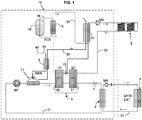
figure 1 représente schématiquement un système de chauffage comprenant une chaudière selon l'invention, - la
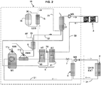
figure 2 représente un système analogue à lafigure 1 , la chaudière comprenant un compresseur thermique, - la
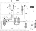
figure 3 représente un système analogue à lafigure 2 , dans lequel l'appoint est délivré directement dans la partie chaude du compresseur thermique, - la
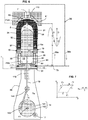
figure 4 représente schématiquement un étage du compresseur thermique, - la
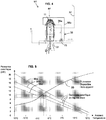
figure 5 illustre un diagramme puissance vs température, - la
figure 6 représente plus en détail un étage du compresseur thermique, - la
figure 7 illustre le cycle thermodynamique, - la
figure 8 illustre la configuration à trois étages du compresseur thermique, - la
figure 9 représente schématiquement un diagramme du système de régulation, - la
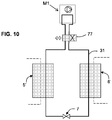
figure 10 illustre la réversibilité de la boucle de pompe à chaleur. - Sur les différentes figures, les mêmes références désignent des éléments identiques ou similaires.
- La
figure 1 montre une vue d'ensemble d'un système de chauffage typiquement prévu pour chauffer un local industriel, une habitation individuelle ou collective. Le système de chauffage comporte une chaudière 10 qui sera décrite dans la suite. - Le système comprend un circuit de chauffage repéré 30 ; comme annoncé au début, le terme « circuit de chauffage » n'exclut pas que ce circuit prélève des calories, toutefois dans le premier exemple tel qu'illustré, le circuit de chauffage comprend des entités réceptrices de calories 3 sous forme des radiateurs/convecteurs 3 et/ou d'un plancher chauffant, situés dans les pièces du local à chauffer.
- Il peut y avoir plusieurs entités réceptrices de calories, par exemple une à basse température (plancher chauffant) et une autre à plus haute température (convecteurs, eau chaude sanitaire). Un circulateur M3 fait circuler de l'eau dans le circuit de chauffage 30.
- Le cas où une entité réceptrice de calories est une piscine ou une serre peut être aussi traité. De même le système de chauffage peut être utilisé dans un contexte industriel avec l'entité réceptrice de calories sous forme d'un équipement de procédé industriel.
- Il est prévu une production d'eau chaude sanitaire ('ECS') avec un ballon de réserve 16 d'eau chaude sanitaire comme connu en soi donc non décrit en détail ici. L'eau de ce ballon de réserve est chauffée par une circulation du fluide 36 lors de son passage dans un échangeur ECS 15.
- Avantageusement dans le cadre de la présente invention, le volume du ballon 16 de réserve peut être très faible par exemple 5 litres, en général inférieur à 10 litres.
- Dans cet échangeur ECS 15 circule une branche de dérivation 33 du circuit de chauffage 30. Cette branche de dérivation prélève des calories dans un échangeur haute température (HT) repéré 50 et les transmet à l'eau chaude sanitaire via l'échangeur ECS 15.
- Le débit de fluide qui circule dans la branche de dérivation 33 peut être commandé par une vanne de régulation ECS 78 connue en soi. Ce débit est déterminé en proportion des besoins du système de régulation du ballon de réserve d'eau chaude sanitaire.
- La chaudière 10 comprend un compresseur M1 qui constitue le composant moteur d'un circuit de pompe à chaleur. Dans l'exemple illustré, seule l'unité extérieure repérée 4 est agencée à l'extérieur du local (bâtiment, habitation, etc) le reste des composants principaux est agencé à l'intérieur du local, voire même dans l'enveloppe de la chaudière 10.
- On note qu'aux figures, les tuyauteries sont représentées de façon symbolique.
- Le dispositif de pompe à chaleur comprend d'une part un circuit d'eau glycolée 34 qui circule dans l'unité extérieure 4, et un circuit 31 de fluide de travail lequel passe au travers du compresseur M1. Dans l'exemple illustré, le fluide de travail est du R744 autrement dit du CO2, mais un autre fluide aux propriétés similaires pourrait être choisi. Afin de le distinguer des autres fluides, on appellera dans la suite le fluide de travail du circuit 31 le fluide « compressible » (aussi appelé dans l'art fluide 'frigorigène'). Ceci par opposition au fluide qui circule vers l'extérieur dans l'unité extérieure (circuit 34) qui est principalement à base d'eau (eau glycolée), et aussi par opposition au fluide qui circule dans le circuit de chauffage 30 déjà mentionné qui est également principalement à base d'eau, donc non compressible.
- Les différents fluides utilisés dans les circuits 30,31,34 sont des fluides caloporteurs, qu'ils soient compressibles ou non, ils permettent de transférer des calories principalement depuis l'unité extérieure 4 vers les entités réceptrices 3, mais aussi depuis le brûleur 11 vers les entités réceptrices 3.
- Le mode de climatisation, aussi possible, sera décrit plus loin.
- Il faut noter que l'unité extérieure 4 peut être une unité aérothermique ou géothermique.
- On remarque que le captage des calories extérieures par l'effet de pompe à chaleur fait appel à deux circuits de fluide en série qui sont interfacés par l'échangeur 6 appelé échangeur d'interface 6, échangeur de préférence à flux croisés. Le circuit d'eau glycolée 34 comprend un circulateur M4, récupère des calories sur l'unité extérieure 4 et délivre ces calories sur l'échangeur d'interface 6. On remarque que l'ensemble du circuit de fluide compressible 31, à savoir celui du CO2, se trouve confiné à l'intérieur de la chaudière 10 ce qui est préparé en usine de fabrication ; seul le circuit d'eau glycolée 34 doit être mis en œuvre par un professionnel sur l'installation cible.
- En outre, le dispositif de pompe à chaleur comprend un détendeur 7, connu en soi, qui joue le rôle inverse du compresseur pour la pression, et un échangeur 5 qui couple thermiquement le circuit du fluide compressible 31 en sortie de compresseur avec le circuit de chauffage 30.
- L'échangeur 5 comprend ici deux échangeurs agencés en série sur le circuit 31 de CO2 : l'échangeur dit «haute température HT » 50 dans lequel circule la dérivation 33 configurée pour réchauffer l'eau chaude sanitaire, et l'échangeur dit « basse température BT » 51 qui forme le couplage principal du circuit de CO2 31 avec le circuit de chauffage 30.
- L'échangeur principal 5 pourrait aussi former un seul échangeur avec une première portion couplée au circuit d'eau chaude sanitaire 33 et une seconde portion couplée au circuit de chauffage 30.
- Le circuit de fluide compressible 31 contient du fluide sous forme diphasique qui récupère des calories sur l'échangeur d'interface 6 (côté dit 'évaporateur' où le fluide diphasique passe de l'état liquide à l'état vapeur) et délivre ces calories sur l'échangeur principal 5 (côté dit 'condenseur' où le fluide diphasique se refroidit). Le fluide compressible se refroidit dans l'échangeur 5, mais reste essentiellement en phase vapeur ; c'est en subissant une détente au niveau du détendeur 7 qu'il passe essentiellement en phase liquide.
- Dans la configuration de la
figure 1 , le compresseur M1 peut être un compresseur à moteur électrique ; dans ce cas, on prévoit en aval du compresseur un brûleur d'appoint 11 qui vient délivrer des calories directement dans le fluide compressible, en aval du compresseur, avec une puissance modulée en adéquation avec la demande d'énergie sur le circuit de chauffage et/ou sur le circuit d'eau chaude sanitaire. - On remarque que les calories de relève sont délivrées dans le fluide compressible et non pas dans un échangeur directement couplé au circuit de chauffage.
- Dans la configuration de la
figure 2 , le compresseur M1 peut être un compresseur de type mû par un moteur à gaz. Le moteur à gaz utilise un brûleur repéré 11a. Le moteur à gaz entraîne ledit compresseur M1 et un autre brûleur 11b forme l'appoint calorifique sur le circuit du fluide compressible comme dans le cas précédent, c'est-à-dire en aval du compresseur M1. - Dans la configuration de la
figure 3 , le compresseur M1 est un compresseur thermique, c'est-à-dire il utilise une énergie calorifique comme source chaude et une source froide ceci pour mettre en action un piston dont le mouvement alternatif et l'utilisation de clapets anti retour forment le compresseur. Un exemple de ce type de compresseur thermique est enseigné en détail dans le documentWO2014202885 et à laFig 6 du présent document. - Dans la configuration de la
figure 3 , il n'y a qu'un seul et unique brûleur 11 qui forme à la fois la source chaude du compresseur thermique M1 et l'appoint calorifique, car en effet avantageusement, à la sortie de l'étage de compression, le fluide compressible R744 est dirigé vers l'environnement brûleur du compresseur et vient y circuler pour prélever des calories du brûleur (sans compression complémentaire à cet endroit). Sur lesFigures 3 ,4 ,6 ,8 , ce circuit de circulation dans la section chaude du compresseur est repéré 38. Il est aussi appelé dans la suite de ce document « circuit de surchauffe » 38. Le circuit de surchauffe 38 comprend une première portion aussi appelée portion amont 38a et une seconde portion aussi appelée portion aval 38b. - On remarque que la circulation dans la section chaude du compresseur est conditionnée par une vanne de régulation d'appoint 75 qui présente un taux d'ouverture quelconque entre deux positions, une première position extrême dans laquelle tout le CO2 est dirigé vers la section chaude du compresseur (cas du besoin d'appoint), et une deuxième position extrême (tout fermé) dans laquelle tout le CO2 est dirigé directement vers l'échangeur principal 5 avec le circuit de chauffage, sans repasser dans la section chaude du compresseur.
- On remarque que lorsque le compresseur M1 fonctionne et le la vanne de sélection 75 est dans la position tout fermé, il se trouve du fluide de travail qui stagne dans le circuit de surchauffe 38, à l'endroit duquel sa température augmente jusqu'à une température voisine de la température du brûleur, à savoir typiquement entre 600°C et 700°C (cf plus loin). Toutefois, en raison des propriétés physiques du fluide choisi, c'est-à-dire le CO2, il n'y a pas de risque de forte surpression voire d'explosion.
- Lorsque le compresseur fonctionne et que la vanne de sélection est dans la première position, dans la partie aval 38b du circuit de recirculation, la température du fluide compressible CO2 est comprise entre 100°C et 300°C et ceci suivant la puissance d'appoint fourni au brûleur.
- Dans la configuration de la
figure 3 , la puissance délivrée au brûleur unique 11 peut être modulée entre 0 et 20kW. Lorsque le compresseur fonctionne sans appoint nécessaire, la puissance délivrée se trouve particulièrement entre 3 et 6kW. Lorsque l'appoint est nécessaire, le compresseur fonctionne (représentant 3 à 6kW) et le reste de la puissance (représentant 2 à 15kW) est apportée depuis le brûleur directement au fluide de travail qui recircule dans le circuit de surchauffe 38. - Le bilan des puissances mises en jeu est illustré à la
Figure 5 . La courbe repérée 55 « puissance disponible hors appoint » représente la somme de la puissance fournie par le compresseur et du prélèvement gratuit d'énergie dans l'environnement extérieur. Les courbes 56a 56b 56c représentent le besoin de chauffage de trois types d'habitation en régime établi. - Le besoin d'appoint se fait sentir lorsque la température extérieure est dans la zone inférieure à un seuil autour de -5° à 0°C.
- En outre, ce diagramme ne représente pas les besoins pic, tels que la production d'eau chaude sanitaire qui dépend du nombre de personnes utilisant les équipements de douche, toilette, cuisine, etc. Ce diagramme ne représente pas non plus le besoin pic de remise en température d'une habitation occupée occasionnellement.
- Dans la configuration des
figures 2 et3 , on remarque que le retour du circuit de chauffage 30 passe d'abord au travers de l'échangeur principal 5,51 puis est dirigé vers la zone froide du compresseur à l'endroit duquel le fluide du circuit de chauffage refroidit le compresseur M1. - On peut prévoir, dans toutes les configurations, que le circuit de sortie des gaz brûlés (noté 32) du brûleur 11 passe à l'intérieur d'un échangeur 21 couplé avec le circuit de chauffage, à l'endroit duquel les fumées (issues de la combustion) cèdent leurs calories au fluide du circuit principal de chauffage 30.
- D'autre part, on peut prévoir, dans toutes les configurations, un échangeur de préchauffage d'admission d'air, repéré 9, par lequel on met à profit des calories présentes dans la sortie des gaz sortant du brûleur 11 pour préchauffer l'air frais 35 admis vers la flamme du brûleur. L'échangeur de préchauffage 9 est ici un échangeur air/air, connu en soi, utilisé à flux croisés dans l'exemple illustré.
- L'air qui arrive dans l'injecteur du brûleur 11 se trouve ainsi à une température comprise entre 100 °C et 200 °C.
- La quantité de gaz introduite et brûlée par le brûleur 11 est commandée par une unité de régulation 1 (cf.
Fig. 9 ) qui contient au moins une boucle d'asservissement pour maintenir la température de la partie chaude du compresseur M1 à une température cible (typiquement entre 600°C et 700°C). L'unité de régulation 1 pilote non seulement la quantité de gaz délivrée au brûleur 11 (avec pilotage de la richesse) mais aussi la vanne 78 de régulation ECS et aussi le cas échéant la vitesse de rotation du moteur de régulation 17 dont il sera question plus loin. En outre, pour gérer le besoin d'appoint de chauffage, l'unité de régulation pilote également la position de la vanne de sélection 75 qui active ou pas le circuit de surchauffe 38. - Plus précisément, on prévoit un capteur de température 61 qui capte la température du carter 110 contenant le brûleur du compresseur (cf.
Fig. 6 ). L'unité de régulation peut aussi recevoir diverses informations de température et de débit 62,63, en provenance du circuit d'eau chaude sanitaire, du thermostat général de régulation du chauffage dans l'habitation sur lequel l'utilisateur indique la température de consigne 66, etc. - La régulation fait intervenir, selon les configurations et les températures courantes, des décisions tout ou rien (cyclage ON/OFF) et/ou des asservissements en continu sur le débit au brûleur, sur la vanne de régulation d'appoint 75 sur la vanne de régulation ECS 78.
- Plus précisément s'agissant de la constitution du compresseur M1, en référence à la
figure 6 , il s'agit d'un compresseur thermique dit 'régénératif' avec une zone d'apport de calories (zone chaude) une zone de refroidissement (zone froide), une enceinte fermée 8 qui communique avec l'extérieur grâce à 2 clapets anti-retour, à savoir un clapet d'entrée 41 (admission) et un clapet de sortie 42 (refoulement). - Dans l'exemple des
Figures 4 et6 , il n'y a qu'un seul étage de compression noté U1, alors que dans l'exemple de laFigure 8 , il s'agit d'une configuration à trois étages de compression autrement dit trois unités de compression U1,U2,U3. - Dans l'enceinte fermée 8, le fluide compressible occupe un volume quasi constant, et un piston déplaceur 71 y est configuré pour se déplacer alternativement, de haut en bas dans l'exemple illustré, afin de déplacer l'essentiel du volume de fluide compressible vers la zone chaude ou vers la zone froide. Le piston est relié à un système d'embiellage et de vilebrequin d'entraînement dans un système d'auto entraînement qui sera vu plus loin.
- Comme représenté à la
Figure 6 , le compresseur est architecturé autour d'une direction axiale X, qui est de préférence disposée verticalement, mais une autre disposition n'est pas exclue. Selon cet axe peut se déplacer le piston 71 monté mobile dans une chemise cylindrique 90. Ledit piston sépare la première chambre 81 et la deuxième chambre 82, ces deux chambres étant incluses dans l'enceinte de travail 8 avec la somme de leurs volumes V1+V2 sensiblement constante. Le piston 71 présente une portion supérieure en forme de dôme, par exemple hémisphérique. - L'enceinte de travail 8 est contenue structurellement dans un assemblage formé d'un carter chaud 96 et d'une culasse froide 95, avec interposition d'un anneau isolateur thermique 97.
- La première chambre 81, dite aussi 'chambre chaude', est agencée au dessus du piston et couplée thermiquement à une source chaude 11 (un brûleur 11 de combustible) qui apporte des calories directement au fluide gazeux. La première chambre est de révolution avec une portion cylindrique de diamètre correspondant au diamètre D1 du piston et une portion hémisphérique en partie supérieure, qui comprend une ouverture centrale 83 pour l'entrée et la sortie du fluide compressible. La source chaude 11 forme une calotte 110 agencée tout autour de la chambre chaude 81, avec un injecteur de brûleur au centre.
- La deuxième chambre 82, dite aussi 'chambre froide', est agencée au dessous du piston et couplée thermiquement à une source froide (ici le retour du circuit de chauffage 91) pour ainsi transférer des calories du fluide compressible vers le circuit de chauffage. La deuxième chambre est cylindrique, de diamètre D1, et comprend plusieurs ouvertures 84 disposées en cercle autour de l'axe, sous le piston, pour l'entrée et la sortie du fluide compressible.
- Autour de la paroi de la chemise cylindrique 90 est agencé un échangeur régénérateur 19, du type de ceux utilisés classiquement dans les machines thermodynamiques de type machine Stirling. Cet échangeur 19 (qu'on appellera aussi simplement 'régénérateur' dans la suite) comprend des canaux fluides de faible section et des éléments de stockage d'énergie thermique et/ou un réseau serré de fils métalliques. Ce régénérateur 19 est agencé à une hauteur intermédiaire entre l'extrémité supérieure et l'extrémité inférieure de l'enceinte et présente un coté chaud 19a vers le haut et un coté froid 19b vers le bas.
- À l'intérieur du régénérateur, on constate entre le côté chaud et le côté froid, un gradient de température important, le côté chaud ayant une température voisine de la température de la calotte du brûleur à savoir 700°C, le côté froid ayant une température voisine de la température du circuit de chauffage à savoir une température comprise entre 30°C et 70°C selon la ou les entité(s) présente(s) sur le circuit de chauffage.
- Un interstice annulaire de circulation 24 agencé contre la surface interne du carter chaud 96 relie l'ouverture 83 de la première chambre jusqu'au côté chaud 19a du régénérateur.
- Des canaux 25 dans la culasse 95 relient les ouvertures 84 de la deuxième chambre jusque au côté froid 19b du régénérateur.
- Ainsi, lorsque le piston monte, le gaz compressible est chassé de la première chambre 81 par l'interstice de circulation 24, le régénérateur 19 et les canaux 25 en direction de la deuxième chambre froide 82. À l'inverse, lorsque le piston redescend, le gaz compressible est chassé de la deuxième chambre froide 82 par les canaux 25, le régénérateur 19 et l'interstice de circulation 24, en direction de la première chambre 81.
- Le fonctionnement du compresseur est assuré par le mouvement alternatif du piston 71 entre le point mort bas PMB et le point de haut PMH, ainsi que par l'action d'un clapet d'aspiration 41 sur l'entrée, d'un clapet anti-retour 42 de refoulement sur la sortie. Les différentes étapes A,B,C,D, décrites ci-après sont représentées sur les figures
- Le piston, initialement en haut, se déplace vers le bas et le volume de la première chambre 81 augmente alors que volume de la deuxième chambre 82 diminue. De par le fait, le fluide est poussé au travers du régénérateur 19 du bas vers le haut, et se réchauffe au passage. La pression Pw augmente de façon concomitante.
- Lorsque la pression Pw dépasse une certaine valeur, le clapet de sortie 42 s'ouvre et la pression Pw s'établit à la pression P2 de sortie du fluide compressé et du fluide est expulsé vers la sortie (le clapet d'entrée 41 reste bien sûr fermé pendant ce temps). Ceci se poursuit jusqu'au point mort bas du piston.
- Le piston, se déplace maintenant du bas vers le haut et le volume de la deuxième chambre augmente alors que première volume de la chambre diminue. De par le fait, le fluide est poussé au travers du régénérateur 19 du haut vers le bas, et se refroidit au passage. La pression Pw diminue de façon concomitante. Le clapet de sortie 42 se ferme en début de montée.
- Lorsque la pression Pw passe en dessous d'une certaine valeur, le clapet d'entrée 41 s'ouvre et la pression Pw s'établit à la pression P1 d'entrée de fluide et du fluide est aspiré par l'entrée (le clapet de sortie 42 reste bien sûr fermé pendant ce temps). Ceci se poursuit jusqu'au point mort haut du piston. Le clapet d'entrée 41 se fermera dès le début de la descente du piston.
- Les mouvements de la tige 18 sont commandés un dispositif d'auto-entrainement 14 agissant sur une extrémité de la tige. Ce dispositif d'auto-entrainement comprend un volant inertiel 142 monté à rotation autour d'un axe Y1, une bielle 141 reliée audit volant par une liaison pivot, par exemple un palier à roulement 143. La bielle 141 est reliée à la tige par une autre liaison pivot, par exemple un palier à roulement 144.
- La chambre auxiliaire 88 remplie du fluide gazeux de travail à une pression notée Pa. Lorsque le dispositif est en fonctionnement, la pression Pa dans la chambre auxiliaire 88 converge vers une pression moyenne sensiblement égale à la demi-somme des pressions mini P1 et maxi P2. En effet, en raison du jeu fonctionnel réduit entre la bague 118 et la tige 18, en régime dynamique, cette très petite fuite ne nuit pas au fonctionnement et reste négligeable.
- Lorsque le volant tourne d'un tour, le piston balaye un volume correspondant à la distance entre le point mort et point mort bas, multipliée par le diamètre Dl.
- Le cycle thermodynamique, tel que représenté à la
figure 7 fournit un travail positif au dispositif d'auto-entrainement. - Toutefois d'une part pour le démarrage initial et pour des besoins de régulation de vitesse de rotation, on prévoit un moteur 17 couplé au volant inertiel 142.
- Ce moteur peut être logé avantageusement dans la chambre auxiliaire 88 ou à l'extérieur avec un couplage magnétique à la paroi.
- Le moteur 17 est piloté par une unité de régulation, non représentée aux figures ; la commande du moteur permet d'accélérer ou de ralentir la vitesse de rotation du volant inertiel, les flux thermiques échangés étant en relation quasi proportionnelle avec la vitesse de rotation du volant inertiel. Grâce au moteur 17, l'unité de régulation peut ajuster la vitesse de rotation entre typiquement 100 trs/m et 500 trs/m, préférentiellement dans la gamme [200 - 300 trs/m].
- On note également que le moteur 17 sert à faire démarrer le dispositif d'auto entraînement 14.
- On remarque que le piston 71 n'est pas un piston récepteur de puissance (à l'inverse d'un moteur à combustion interne ou d'un moteur Stirling classique) mais simplement un piston déplaceur ; la puissance est fournie sous forme d'augmentation de pression de gaz de travail.
- On note que V1 + V2 + Vcanal = Vtotal si on fait abstraction des variations du volume de la tige 18, V1 étant le volume de la première chambre, V2 étant le volume de la deuxième chambre et Vcanal étant le volume des canalisations 24,25 . De préférence on s'arrange pour avoir un volume mort de plus faible possible avec des canalisations de petite section, par exemple on obtiendra Vcanal < 10% de V1+V2.
- On illustre à la
figure 8 une caractéristique complémentaire, à savoir une configuration à trois étages de compression autrement dit trois unités de compression U1,U2,U3. - Le deuxième étage U2 et le troisième étage U3 sont similaires ou analogue en tout point au premier étage Ul; chacun comprend un brûleur 12,13 à l'endroit duquel la combustion de gaz mélangé à l'air admis se produit, et un piston déplaceur 72,73 analogues à celui du premier étage et dont le mouvement et la vitesse de rotation sont indépendants du premier.
- Avantageusement, les étages fonctionnent de manière indépendante, la vitesse de rotation peut être différente d'un étage à l'autre.
- On remarque que le circuit de chauffage refroidit les trois zones froides des compresseurs, par les canaux successifs 93, 92 et 91.
- La sortie du premier étage c'est-à-dire le clapet 42 est reliée à l'entrée du deuxième étage c'est-à-dire le clapet 43, La sortie du deuxième étage c'est-à-dire le clapet 44 est reliée à l'entrée du troisième étage c'est-à-dire le clapet 45. La sortie du clapet 46 forme la sortie générale du compresseur 1.
- L'étagement des pressions peut être typiquement le suivant, la pression d'admission du premier étage U1 est de l'ordre de 20 bars, la pression de refoulement du premier étage (admission deuxième étage) est de l'ordre de 40 bars ; la pression de refoulement du deuxième étage U2 (admission troisième étage) est de l'ordre de 60bars ; la sortie du troisième étage U3 peut être de l'ordre de 80 bars.
- On peut prévoir que les trois zones froides des trois étages U1 U2 U3 forment une seule pièce appelée culasse froide.
- Bien entendu, on peut aussi avoir une configuration à deux étages U1 U2.
- En outre, il est possible de prévoir une configuration dans laquelle deux étages (ou plus) sont disposés en parallèle, les étages étant similaires à ceux décrits ci-dessus.
- D'une façon générale, on remarque que le combustible utilisé dans le brûleur peut être du gaz naturel, ou du bio gaz d'origine végétale ou animale, ou des composés hydrocarbures légers déchets de processus industriels pétroliers.
- Hormis le cas de l'eau chaude sanitaire, un besoin de puissance important existe dans le cas d'une résidence secondaire qui doit être mise en température au moment de l'arrivée des occupants occasionnels. La configuration présentée permet de délivrer plus de 20 kW pendant un temps relativement long pour la mise en température du logement.
- Comme illustré à la
figure 10 , le compresseur thermique 1 décrit ci-dessus peut être utilisé dans le contexte des schémas desfigures 1 à 3 , bien sûr dans un mode de chauffage, mais aussi moyennant sa réversibilité dans un dit de climatisation. - En l'occurrence, dans ce mode climatisation, on va prélever des calories sur le circuit de chauffage 30 (par exemple au niveau d'un plancher chauffant) et les calories prélevées vont être dirigées soient vers le circuit d'eau chaude sanitaire 15,16, soit vers l'unité extérieure 4.
- Ce résultat peut être obtenu en inversant le rôle des échangeurs 5',6' d'évaporation et de condensation sur la boucle du gaz compressible 31.
- Pour des raisons de clarté la vanne 77 à quatre voies qui permet d'inverser le sens de circulation du fluide n'a pas été représentée sur les
figures 1 à 3 , mais le principe est représenté à lafigure 10 où la vanne 77 à quatre voies présente une position normale dite de mode de chauffage et une position spéciale (inversée) dite de mode de climatisation, qui inverse les rôles des échangeurs repérés 5' et 6' comme connu en soi. - Dans le système de la chaudière, pour des raisons de clarté, certains composants n'ont pas été représentés bien qu'ils puissent être également présents. Il s'agit notamment de :
- les vases d'expansion sur des circuits d'eau 34, 30
- les robinets de remplissage et de purge du circuit de chauffage
- les robinets de remplissage et de purge du circuit CO2
- divers manomètres et capteurs de température nécessaires au pilotage du système par l'unité de régulation
-
- 30 : circuit de chauffage
- 31 : fluide compressible CO2
- 32 : fumées de combustion
- 33 : dérivation pour ECS
- 34 : eau glycolée (échange avec l'extérieur)
- 35 : air admis réchauffé
- 36 : circuit spécifique ECS
Claims (12)
- Système de chauffage comprenant un circuit de chauffage (30) et une chaudière thermodynamique configurée pour au moins délivrer des calories dans ledit au moins un circuit de chauffage (30), la chaudière comprenant au moins un compresseur (M1) formant la fonction compression d'une boucle de type pompe à chaleur (31,34) utilisant un fluide frigorigène, la chaudière comprenant en outre un brûleur (11) de combustible qui délivre des calories au moins dans le fluide frigorigène, caractérisée en ce que le brûleur de combustible délivre les calories dans le fluide frigorigène, en aval du compresseur.
- Système de chauffage selon la revendication 1, dans lequel le fluide frigorigène est un fluide compressible de type R744 (CO2).
- Système de chauffage selon l'une des revendications 1 à 2, dans lequel le compresseur est un compresseur thermique comprenant au moins un étage de compression avec piston (71) à déplacement alternatif, le brûleur (11,11a) de combustible formant en outre la source chaude du compresseur et le circuit de chauffage formant la source froide du compresseur.
- Système de chauffage selon la revendication 3, comprenant un circuit d'eau chaude sanitaire (15,16).
- Système de chauffage selon l'une des revendications 3 à 4, dans lequel le brûleur (11) du compresseur forme l'unique brûleur de la chaudière.
- Système de chauffage selon l'une des revendications 3 à 5, comprenant un circuit de surchauffe (38) du fluide compressible dans ou au voisinage immédiat du brûleur, et une vanne de régulation d'appoint (75) permettant de faire sélectivement circuler le fluide compressible dans ledit circuit de surchauffe.
- Système de chauffage selon l'une des revendications 3 à 6, dans lequel le brûleur (11) du compresseur permet de délivrer la totalité de la puissance de la chaudière.
- Système de chauffage selon l'une des revendications 4 ou l'une des revendications 5 à 7 lorsqu'elles dépendent de la revendication 4, comprenant un échangeur (5) formant l'interface thermique essentielle entre la boucle de type pompe à chaleur (31) et le circuit de chauffage (30), l'échangeur (5) comprenant un échangeur haute température (50) et un échangeur basse température (51), l'échangeur haute température étant couplé au circuit d'eau chaude sanitaire (15,16),
- Système de chauffage selon l'une des revendications 3 à 8, dans lequel la boucle de type pompe à chaleur comprend deux circuits disposés en cascade, à savoir un circuit de travail de gaz compressible R744 (31,M1,5,7,6) et un circuit d'eau glycolée (34,4,6).
- Système de chauffage selon l'une des revendications 3 à 9, dans lequel il est prévu une unité de modulation et un moteur (17) pour réguler, à savoir augmenter et/ou diminuer la vitesse de rotation du compresseur.
- Système de chauffage selon l'une des revendications 3 à 10, dans lequel le compresseur comprend au moins deux étages de compression en série, à savoir un premier étage de compression (U1) et un deuxième étage de compression (U2).
- Système de chauffage selon la revendication 11, dans lequel le compresseur comprend trois étages (U1,U2,U3).
Priority Applications (1)
| Application Number | Priority Date | Filing Date | Title |
|---|---|---|---|
| PL18720327T PL3612769T3 (pl) | 2017-04-20 | 2018-04-12 | Kocioł termodynamiczny na CO2 i sprężarka termiczna |
Applications Claiming Priority (2)
| Application Number | Priority Date | Filing Date | Title |
|---|---|---|---|
| FR1753447A FR3065515B1 (fr) | 2017-04-20 | 2017-04-20 | Chaudiere thermodynamique a co2 et compresseur thermique |
| PCT/FR2018/050925 WO2018193188A1 (fr) | 2017-04-20 | 2018-04-12 | Chaudière thermodynamique à co2 et compresseur thermique |
Publications (2)
| Publication Number | Publication Date |
|---|---|
| EP3612769A1 EP3612769A1 (fr) | 2020-02-26 |
| EP3612769B1 true EP3612769B1 (fr) | 2021-03-24 |
Family
ID=59297038
Family Applications (1)
| Application Number | Title | Priority Date | Filing Date |
|---|---|---|---|
| EP18720327.8A Active EP3612769B1 (fr) | 2017-04-20 | 2018-04-12 | Chaudière thermodynamique à co2 et compresseur thermique |
Country Status (13)
| Country | Link |
|---|---|
| US (1) | US20210108804A1 (fr) |
| EP (1) | EP3612769B1 (fr) |
| JP (1) | JP7311426B2 (fr) |
| CN (1) | CN110869675B (fr) |
| CA (1) | CA3060933A1 (fr) |
| CY (1) | CY1124249T1 (fr) |
| DK (1) | DK3612769T3 (fr) |
| ES (1) | ES2872251T3 (fr) |
| FR (1) | FR3065515B1 (fr) |
| PL (1) | PL3612769T3 (fr) |
| PT (1) | PT3612769T (fr) |
| RU (1) | RU2757310C2 (fr) |
| WO (1) | WO2018193188A1 (fr) |
Families Citing this family (5)
| Publication number | Priority date | Publication date | Assignee | Title |
|---|---|---|---|---|
| WO2021094867A1 (fr) | 2019-11-15 | 2021-05-20 | Studieburo B | Dispositif et procédé de compression thermique d'un milieu |
| BE1027752B1 (nl) | 2019-11-15 | 2021-06-14 | Studieburo B | Inrichting en werkwijze voor de thermische compressie van een medium |
| CN113357692A (zh) * | 2021-06-04 | 2021-09-07 | 中国科学院广州能源研究所 | 一种火电厂循环水余热回收系统 |
| CN113959118A (zh) * | 2021-11-29 | 2022-01-21 | 中印恒盛(北京)贸易有限公司 | 一种用于燃煤锅炉快速降温使用的导冷筒 |
| US20250027688A1 (en) * | 2023-07-21 | 2025-01-23 | Trane International Inc | Integrated heating system using a stirling heat pump |
Family Cites Families (24)
| Publication number | Priority date | Publication date | Assignee | Title |
|---|---|---|---|---|
| JPS5021763U (fr) * | 1973-06-20 | 1975-03-12 | ||
| JPS5810938Y2 (ja) * | 1975-04-11 | 1983-02-28 | 松下電器産業株式会社 | レイダンボウキユウトウソウチ |
| DE2758773C2 (de) * | 1977-12-29 | 1981-12-17 | Ask August Schneider Gmbh & Co Kg, 8650 Kulmbach | Bivalente Heizanlage |
| JPS57175858A (en) * | 1981-04-23 | 1982-10-28 | Mitsubishi Electric Corp | Air conditionor |
| JPS5912255A (ja) * | 1982-07-14 | 1984-01-21 | 株式会社日立製作所 | ヒ−トポンプエアコン |
| JPS6196374A (ja) * | 1984-10-16 | 1986-05-15 | サンデン株式会社 | 暖房給湯装置 |
| DE4006742A1 (de) * | 1990-03-03 | 1991-09-05 | Messerschmitt Boelkow Blohm | Heizungs- und stromerzeugungsanlage |
| JP2001280733A (ja) | 2000-03-31 | 2001-10-10 | Daikin Ind Ltd | 加熱装置及びこれを備える空気調和装置 |
| CN2781011Y (zh) * | 2004-11-09 | 2006-05-17 | 青岛威能动力有限公司 | 直线内燃式流体泵 |
| CN100402814C (zh) * | 2005-01-20 | 2008-07-16 | 华南理工大学 | 一种天然气冷热电联供的烟气低温端热利用系统 |
| KR100790378B1 (ko) * | 2006-06-22 | 2008-01-02 | 주식회사 한두아이펨 | 엔진개조형 냉매압축기 및 이를 구비하는 냉난방장치 |
| CN201311057Y (zh) * | 2008-11-01 | 2009-09-16 | 广东万和新电气有限公司 | 带燃气辅助加热工质装置的热泵热水器 |
| FR2971562B1 (fr) * | 2011-02-10 | 2013-03-29 | Jacquet Luc | Dispositif de compression de fluide gazeux |
| JP5636406B2 (ja) * | 2012-09-04 | 2014-12-03 | リンナイ株式会社 | 暖房システム |
| ITBO20120650A1 (it) | 2012-11-30 | 2014-05-31 | Gas Point S R L | Apparecchiatura di riscaldamento comprendente una caldaia a condensazione ed una pompa di calore |
| CN103114941B (zh) * | 2013-02-01 | 2015-04-15 | 中国科学院理化技术研究所 | 一种同时利用高低温热源的自由活塞斯特林发动机系统 |
| FR3005150B1 (fr) * | 2013-04-24 | 2016-11-04 | Boostheat | Methode et dispositif pour indiquer la consommation et/ou l'efficacite d'une installation de chauffage |
| FR3007077B1 (fr) * | 2013-06-18 | 2017-12-22 | Boostheat | Dispositif de compression thermique de fluide gazeux |
| GR1008430B (el) * | 2013-08-30 | 2015-02-13 | ΠΑΠΑΔΙΑΜΑΝΤΗΣ-ΑΡΑΠΚΟΥΛΕΣ ΙΚΕ με δ.τ. "INNOVATIVE DEVELOPMENT PC", | Θερμικος συμπιεστης |
| JP2015068577A (ja) | 2013-09-30 | 2015-04-13 | リンナイ株式会社 | ヒートポンプ装置および給湯暖房装置 |
| US10527294B2 (en) * | 2013-10-14 | 2020-01-07 | Grundfos Holding A/S | Control of a pump to optimize heat transfer |
| CN104456610B (zh) * | 2014-12-02 | 2017-10-17 | 新疆工程学院 | 一种蒸汽喷射式热泵循环的烟气余热回收系统 |
| FR3042857B1 (fr) * | 2015-10-23 | 2019-06-28 | Boostheat | Chaudiere thermodynamique a compresseur thermique |
| RU2736684C1 (ru) * | 2020-03-27 | 2020-11-19 | Михаил Иванович Голубенко | Способ работы отопительного котла в системе отопления |
-
2017
- 2017-04-20 FR FR1753447A patent/FR3065515B1/fr not_active Expired - Fee Related
-
2018
- 2018-04-12 RU RU2019136955A patent/RU2757310C2/ru active
- 2018-04-12 PL PL18720327T patent/PL3612769T3/pl unknown
- 2018-04-12 EP EP18720327.8A patent/EP3612769B1/fr active Active
- 2018-04-12 US US16/606,682 patent/US20210108804A1/en not_active Abandoned
- 2018-04-12 ES ES18720327T patent/ES2872251T3/es active Active
- 2018-04-12 DK DK18720327.8T patent/DK3612769T3/da active
- 2018-04-12 CA CA3060933A patent/CA3060933A1/fr active Pending
- 2018-04-12 CN CN201880040689.7A patent/CN110869675B/zh not_active Expired - Fee Related
- 2018-04-12 JP JP2019556796A patent/JP7311426B2/ja active Active
- 2018-04-12 WO PCT/FR2018/050925 patent/WO2018193188A1/fr not_active Ceased
- 2018-04-12 PT PT187203278T patent/PT3612769T/pt unknown
-
2021
- 2021-05-25 CY CY20211100450T patent/CY1124249T1/el unknown
Non-Patent Citations (1)
| Title |
|---|
| None * |
Also Published As
| Publication number | Publication date |
|---|---|
| CA3060933A1 (fr) | 2018-10-25 |
| FR3065515A1 (fr) | 2018-10-26 |
| JP2020517885A (ja) | 2020-06-18 |
| RU2019136955A3 (fr) | 2021-08-10 |
| CY1124249T1 (el) | 2022-07-22 |
| ES2872251T3 (es) | 2021-11-02 |
| CN110869675B (zh) | 2021-09-24 |
| US20210108804A1 (en) | 2021-04-15 |
| PT3612769T (pt) | 2021-05-25 |
| WO2018193188A1 (fr) | 2018-10-25 |
| JP7311426B2 (ja) | 2023-07-19 |
| EP3612769A1 (fr) | 2020-02-26 |
| PL3612769T3 (pl) | 2021-10-25 |
| CN110869675A (zh) | 2020-03-06 |
| RU2019136955A (ru) | 2021-05-20 |
| FR3065515B1 (fr) | 2019-09-27 |
| DK3612769T3 (da) | 2021-05-31 |
| RU2757310C2 (ru) | 2021-10-13 |
Similar Documents
| Publication | Publication Date | Title |
|---|---|---|
| EP3612769B1 (fr) | Chaudière thermodynamique à co2 et compresseur thermique | |
| FR3042857B1 (fr) | Chaudiere thermodynamique a compresseur thermique | |
| FR2948992A1 (fr) | Dispositif thermodynamique multi-energie modulaire | |
| WO2018125535A1 (fr) | Utilisation d'air externe pour une commande d'inventaire à cycle fermé | |
| EP2729741A1 (fr) | Systeme d'echange thermique et procede de regulation d'une puissance thermique developpee par un tel systeme d'echange thermique | |
| EP2511627A1 (fr) | Pompe à chaleur bi-étagée à hautes performances | |
| WO2014044864A1 (fr) | Installation de chauffe-eau sanitaire à fonction de chauffage | |
| US20210190328A1 (en) | Combined heating and cooling system | |
| WO2008037896A2 (fr) | Module utilisable pour le stockage et le transfert thermique | |
| EP2318783B1 (fr) | Système réversible de récupération d'énergie calorifique par prélèvement et transfert de calories d'un ou plusieurs milieux dans un autre ou plusieurs autres milieux quelconques | |
| EP4644801A1 (fr) | Installation thermique multifonctionnelle, comprenant une pompe à chaleur à quantité réduite de fluide frigorigène | |
| WO2010043829A2 (fr) | Pompe a chaleur | |
| US12287656B2 (en) | Control systems for use in critical power applications | |
| FR2906603A1 (fr) | Module utilisable pour le stockage et le transfert thermique | |
| FR3078387A1 (fr) | Complexe de traitement d'air avec pompe a chaleur hybride reversible et polyvalente | |
| FR2976657A1 (fr) | Echangeur thermique et utilisation d'un tel echangeur thermique pour la recuperation de l'energie d'eaux usees ou eaux a basse temperature. | |
| WO2013104838A1 (fr) | Dispositif thermodynamique pour chauffer et/ou climatiser un volume |
Legal Events
| Date | Code | Title | Description |
|---|---|---|---|
| STAA | Information on the status of an ep patent application or granted ep patent |
Free format text: STATUS: UNKNOWN |
|
| STAA | Information on the status of an ep patent application or granted ep patent |
Free format text: STATUS: THE INTERNATIONAL PUBLICATION HAS BEEN MADE |
|
| PUAI | Public reference made under article 153(3) epc to a published international application that has entered the european phase |
Free format text: ORIGINAL CODE: 0009012 |
|
| STAA | Information on the status of an ep patent application or granted ep patent |
Free format text: STATUS: REQUEST FOR EXAMINATION WAS MADE |
|
| 17P | Request for examination filed |
Effective date: 20191011 |
|
| AK | Designated contracting states |
Kind code of ref document: A1 Designated state(s): AL AT BE BG CH CY CZ DE DK EE ES FI FR GB GR HR HU IE IS IT LI LT LU LV MC MK MT NL NO PL PT RO RS SE SI SK SM TR |
|
| AX | Request for extension of the european patent |
Extension state: BA ME |
|
| DAV | Request for validation of the european patent (deleted) | ||
| DAX | Request for extension of the european patent (deleted) | ||
| GRAP | Despatch of communication of intention to grant a patent |
Free format text: ORIGINAL CODE: EPIDOSNIGR1 |
|
| STAA | Information on the status of an ep patent application or granted ep patent |
Free format text: STATUS: GRANT OF PATENT IS INTENDED |
|
| INTG | Intention to grant announced |
Effective date: 20201110 |
|
| GRAS | Grant fee paid |
Free format text: ORIGINAL CODE: EPIDOSNIGR3 |
|
| GRAA | (expected) grant |
Free format text: ORIGINAL CODE: 0009210 |
|
| STAA | Information on the status of an ep patent application or granted ep patent |
Free format text: STATUS: THE PATENT HAS BEEN GRANTED |
|
| AK | Designated contracting states |
Kind code of ref document: B1 Designated state(s): AL AT BE BG CH CY CZ DE DK EE ES FI FR GB GR HR HU IE IS IT LI LT LU LV MC MK MT NL NO PL PT RO RS SE SI SK SM TR |
|
| REG | Reference to a national code |
Ref country code: GB Ref legal event code: FG4D Free format text: NOT ENGLISH |
|
| REG | Reference to a national code |
Ref country code: CH Ref legal event code: EP |
|
| REG | Reference to a national code |
Ref country code: IE Ref legal event code: FG4D Free format text: LANGUAGE OF EP DOCUMENT: FRENCH |
|
| REG | Reference to a national code |
Ref country code: AT Ref legal event code: REF Ref document number: 1374856 Country of ref document: AT Kind code of ref document: T Effective date: 20210415 Ref country code: DE Ref legal event code: R096 Ref document number: 602018014390 Country of ref document: DE |
|
| REG | Reference to a national code |
Ref country code: FI Ref legal event code: FGE |
|
| REG | Reference to a national code |
Ref country code: PT Ref legal event code: SC4A Ref document number: 3612769 Country of ref document: PT Date of ref document: 20210525 Kind code of ref document: T Free format text: AVAILABILITY OF NATIONAL TRANSLATION Effective date: 20210519 |
|
| REG | Reference to a national code |
Ref country code: NL Ref legal event code: FP |
|
| REG | Reference to a national code |
Ref country code: DK Ref legal event code: T3 Effective date: 20210526 |
|
| REG | Reference to a national code |
Ref country code: SE Ref legal event code: TRGR |
|
| REG | Reference to a national code |
Ref country code: NO Ref legal event code: T2 Effective date: 20210324 |
|
| REG | Reference to a national code |
Ref country code: GR Ref legal event code: EP Ref document number: 20210401627 Country of ref document: GR Effective date: 20210709 |
|
| REG | Reference to a national code |
Ref country code: LT Ref legal event code: MG9D |
|
| PG25 | Lapsed in a contracting state [announced via postgrant information from national office to epo] |
Ref country code: HR Free format text: LAPSE BECAUSE OF FAILURE TO SUBMIT A TRANSLATION OF THE DESCRIPTION OR TO PAY THE FEE WITHIN THE PRESCRIBED TIME-LIMIT Effective date: 20210324 Ref country code: BG Free format text: LAPSE BECAUSE OF FAILURE TO SUBMIT A TRANSLATION OF THE DESCRIPTION OR TO PAY THE FEE WITHIN THE PRESCRIBED TIME-LIMIT Effective date: 20210624 |
|
| PGFP | Annual fee paid to national office [announced via postgrant information from national office to epo] |
Ref country code: PT Payment date: 20210525 Year of fee payment: 4 Ref country code: NO Payment date: 20210521 Year of fee payment: 4 Ref country code: FI Payment date: 20210423 Year of fee payment: 4 Ref country code: MC Payment date: 20210427 Year of fee payment: 4 |
|
| PG25 | Lapsed in a contracting state [announced via postgrant information from national office to epo] |
Ref country code: LV Free format text: LAPSE BECAUSE OF FAILURE TO SUBMIT A TRANSLATION OF THE DESCRIPTION OR TO PAY THE FEE WITHIN THE PRESCRIBED TIME-LIMIT Effective date: 20210324 Ref country code: RS Free format text: LAPSE BECAUSE OF FAILURE TO SUBMIT A TRANSLATION OF THE DESCRIPTION OR TO PAY THE FEE WITHIN THE PRESCRIBED TIME-LIMIT Effective date: 20210324 |
|
| PGFP | Annual fee paid to national office [announced via postgrant information from national office to epo] |
Ref country code: DK Payment date: 20210630 Year of fee payment: 4 Ref country code: ES Payment date: 20210607 Year of fee payment: 4 |
|
| PGFP | Annual fee paid to national office [announced via postgrant information from national office to epo] |
Ref country code: IS Payment date: 20210426 Year of fee payment: 4 |
|
| PG25 | Lapsed in a contracting state [announced via postgrant information from national office to epo] |
Ref country code: SM Free format text: LAPSE BECAUSE OF FAILURE TO SUBMIT A TRANSLATION OF THE DESCRIPTION OR TO PAY THE FEE WITHIN THE PRESCRIBED TIME-LIMIT Effective date: 20210324 Ref country code: LT Free format text: LAPSE BECAUSE OF FAILURE TO SUBMIT A TRANSLATION OF THE DESCRIPTION OR TO PAY THE FEE WITHIN THE PRESCRIBED TIME-LIMIT Effective date: 20210324 Ref country code: EE Free format text: LAPSE BECAUSE OF FAILURE TO SUBMIT A TRANSLATION OF THE DESCRIPTION OR TO PAY THE FEE WITHIN THE PRESCRIBED TIME-LIMIT Effective date: 20210324 Ref country code: CZ Free format text: LAPSE BECAUSE OF FAILURE TO SUBMIT A TRANSLATION OF THE DESCRIPTION OR TO PAY THE FEE WITHIN THE PRESCRIBED TIME-LIMIT Effective date: 20210324 |
|
| PGFP | Annual fee paid to national office [announced via postgrant information from national office to epo] |
Ref country code: NL Payment date: 20210423 Year of fee payment: 4 Ref country code: CY Payment date: 20210426 Year of fee payment: 4 |
|
| REG | Reference to a national code |
Ref country code: ES Ref legal event code: FG2A Ref document number: 2872251 Country of ref document: ES Kind code of ref document: T3 Effective date: 20211102 |
|
| PG25 | Lapsed in a contracting state [announced via postgrant information from national office to epo] |
Ref country code: SK Free format text: LAPSE BECAUSE OF FAILURE TO SUBMIT A TRANSLATION OF THE DESCRIPTION OR TO PAY THE FEE WITHIN THE PRESCRIBED TIME-LIMIT Effective date: 20210324 Ref country code: RO Free format text: LAPSE BECAUSE OF FAILURE TO SUBMIT A TRANSLATION OF THE DESCRIPTION OR TO PAY THE FEE WITHIN THE PRESCRIBED TIME-LIMIT Effective date: 20210324 |
|
| PGFP | Annual fee paid to national office [announced via postgrant information from national office to epo] |
Ref country code: GR Payment date: 20210702 Year of fee payment: 4 |
|
| REG | Reference to a national code |
Ref country code: DE Ref legal event code: R097 Ref document number: 602018014390 Country of ref document: DE |
|
| PG25 | Lapsed in a contracting state [announced via postgrant information from national office to epo] |
Ref country code: AL Free format text: LAPSE BECAUSE OF FAILURE TO SUBMIT A TRANSLATION OF THE DESCRIPTION OR TO PAY THE FEE WITHIN THE PRESCRIBED TIME-LIMIT Effective date: 20210324 |
|
| PGFP | Annual fee paid to national office [announced via postgrant information from national office to epo] |
Ref country code: SE Payment date: 20210423 Year of fee payment: 4 |
|
| PLBE | No opposition filed within time limit |
Free format text: ORIGINAL CODE: 0009261 |
|
| STAA | Information on the status of an ep patent application or granted ep patent |
Free format text: STATUS: NO OPPOSITION FILED WITHIN TIME LIMIT |
|
| PG25 | Lapsed in a contracting state [announced via postgrant information from national office to epo] |
Ref country code: SI Free format text: LAPSE BECAUSE OF FAILURE TO SUBMIT A TRANSLATION OF THE DESCRIPTION OR TO PAY THE FEE WITHIN THE PRESCRIBED TIME-LIMIT Effective date: 20210324 |
|
| 26N | No opposition filed |
Effective date: 20220104 |
|
| PGFP | Annual fee paid to national office [announced via postgrant information from national office to epo] |
Ref country code: PL Payment date: 20210427 Year of fee payment: 4 |
|
| REG | Reference to a national code |
Ref country code: DK Ref legal event code: EBP Effective date: 20220430 |
|
| REG | Reference to a national code |
Ref country code: NO Ref legal event code: MMEP |
|
| REG | Reference to a national code |
Ref country code: SE Ref legal event code: EUG |
|
| REG | Reference to a national code |
Ref country code: NL Ref legal event code: MM Effective date: 20220501 |
|
| PG25 | Lapsed in a contracting state [announced via postgrant information from national office to epo] |
Ref country code: SE Free format text: LAPSE BECAUSE OF NON-PAYMENT OF DUE FEES Effective date: 20220413 Ref country code: NO Free format text: LAPSE BECAUSE OF NON-PAYMENT OF DUE FEES Effective date: 20220430 Ref country code: NL Free format text: LAPSE BECAUSE OF NON-PAYMENT OF DUE FEES Effective date: 20220501 Ref country code: MC Free format text: LAPSE BECAUSE OF NON-PAYMENT OF DUE FEES Effective date: 20220502 Ref country code: FI Free format text: LAPSE BECAUSE OF NON-PAYMENT OF DUE FEES Effective date: 20220412 Ref country code: CY Free format text: LAPSE BECAUSE OF NON-PAYMENT OF DUE FEES Effective date: 20220412 |
|
| PG25 | Lapsed in a contracting state [announced via postgrant information from national office to epo] |
Ref country code: GR Free format text: LAPSE BECAUSE OF NON-PAYMENT OF DUE FEES Effective date: 20221107 |
|
| REG | Reference to a national code |
Ref country code: AT Ref legal event code: UEP Ref document number: 1374856 Country of ref document: AT Kind code of ref document: T Effective date: 20210324 |
|
| PG25 | Lapsed in a contracting state [announced via postgrant information from national office to epo] |
Ref country code: PT Free format text: LAPSE BECAUSE OF NON-PAYMENT OF DUE FEES Effective date: 20230112 Ref country code: DK Free format text: LAPSE BECAUSE OF NON-PAYMENT OF DUE FEES Effective date: 20220430 |
|
| REG | Reference to a national code |
Ref country code: ES Ref legal event code: FD2A Effective date: 20230526 |
|
| PGFP | Annual fee paid to national office [announced via postgrant information from national office to epo] |
Ref country code: LU Payment date: 20230526 Year of fee payment: 6 |
|
| PG25 | Lapsed in a contracting state [announced via postgrant information from national office to epo] |
Ref country code: HU Free format text: LAPSE BECAUSE OF FAILURE TO SUBMIT A TRANSLATION OF THE DESCRIPTION OR TO PAY THE FEE WITHIN THE PRESCRIBED TIME-LIMIT; INVALID AB INITIO Effective date: 20180412 Ref country code: ES Free format text: LAPSE BECAUSE OF NON-PAYMENT OF DUE FEES Effective date: 20220413 |
|
| PGFP | Annual fee paid to national office [announced via postgrant information from national office to epo] |
Ref country code: IT Payment date: 20230609 Year of fee payment: 6 Ref country code: IE Payment date: 20230525 Year of fee payment: 6 Ref country code: FR Payment date: 20230530 Year of fee payment: 6 Ref country code: DE Payment date: 20230613 Year of fee payment: 6 Ref country code: CH Payment date: 20230701 Year of fee payment: 6 |
|
| PGFP | Annual fee paid to national office [announced via postgrant information from national office to epo] |
Ref country code: AT Payment date: 20230321 Year of fee payment: 6 |
|
| PGFP | Annual fee paid to national office [announced via postgrant information from national office to epo] |
Ref country code: BE Payment date: 20230526 Year of fee payment: 6 |
|
| PGFP | Annual fee paid to national office [announced via postgrant information from national office to epo] |
Ref country code: GB Payment date: 20230424 Year of fee payment: 6 |
|
| PG25 | Lapsed in a contracting state [announced via postgrant information from national office to epo] |
Ref country code: MK Free format text: LAPSE BECAUSE OF FAILURE TO SUBMIT A TRANSLATION OF THE DESCRIPTION OR TO PAY THE FEE WITHIN THE PRESCRIBED TIME-LIMIT Effective date: 20210324 |
|
| PG25 | Lapsed in a contracting state [announced via postgrant information from national office to epo] |
Ref country code: PL Free format text: LAPSE BECAUSE OF NON-PAYMENT OF DUE FEES Effective date: 20220412 |
|
| PG25 | Lapsed in a contracting state [announced via postgrant information from national office to epo] |
Ref country code: MT Free format text: LAPSE BECAUSE OF FAILURE TO SUBMIT A TRANSLATION OF THE DESCRIPTION OR TO PAY THE FEE WITHIN THE PRESCRIBED TIME-LIMIT Effective date: 20210324 |
|
| REG | Reference to a national code |
Ref country code: DE Ref legal event code: R119 Ref document number: 602018014390 Country of ref document: DE |
|
| REG | Reference to a national code |
Ref country code: CH Ref legal event code: PL |
|
| REG | Reference to a national code |
Ref country code: AT Ref legal event code: MM01 Ref document number: 1374856 Country of ref document: AT Kind code of ref document: T Effective date: 20240412 |
|
| PG25 | Lapsed in a contracting state [announced via postgrant information from national office to epo] |
Ref country code: LU Free format text: LAPSE BECAUSE OF NON-PAYMENT OF DUE FEES Effective date: 20240412 |
|
| GBPC | Gb: european patent ceased through non-payment of renewal fee |
Effective date: 20240412 |
|
| REG | Reference to a national code |
Ref country code: BE Ref legal event code: MM Effective date: 20240430 |
|
| PG25 | Lapsed in a contracting state [announced via postgrant information from national office to epo] |
Ref country code: LU Free format text: LAPSE BECAUSE OF NON-PAYMENT OF DUE FEES Effective date: 20240412 |
|
| PG25 | Lapsed in a contracting state [announced via postgrant information from national office to epo] |
Ref country code: DE Free format text: LAPSE BECAUSE OF NON-PAYMENT OF DUE FEES Effective date: 20241105 |
|
| PG25 | Lapsed in a contracting state [announced via postgrant information from national office to epo] |
Ref country code: BE Free format text: LAPSE BECAUSE OF NON-PAYMENT OF DUE FEES Effective date: 20240430 |
|
| PG25 | Lapsed in a contracting state [announced via postgrant information from national office to epo] |
Ref country code: GB Free format text: LAPSE BECAUSE OF NON-PAYMENT OF DUE FEES Effective date: 20240412 |
|
| PG25 | Lapsed in a contracting state [announced via postgrant information from national office to epo] |
Ref country code: FR Free format text: LAPSE BECAUSE OF NON-PAYMENT OF DUE FEES Effective date: 20240430 |
|
| PG25 | Lapsed in a contracting state [announced via postgrant information from national office to epo] |
Ref country code: AT Free format text: LAPSE BECAUSE OF NON-PAYMENT OF DUE FEES Effective date: 20240412 |
|
| PG25 | Lapsed in a contracting state [announced via postgrant information from national office to epo] |
Ref country code: GB Free format text: LAPSE BECAUSE OF NON-PAYMENT OF DUE FEES Effective date: 20240412 Ref country code: FR Free format text: LAPSE BECAUSE OF NON-PAYMENT OF DUE FEES Effective date: 20240430 Ref country code: DE Free format text: LAPSE BECAUSE OF NON-PAYMENT OF DUE FEES Effective date: 20241105 Ref country code: BE Free format text: LAPSE BECAUSE OF NON-PAYMENT OF DUE FEES Effective date: 20240430 Ref country code: AT Free format text: LAPSE BECAUSE OF NON-PAYMENT OF DUE FEES Effective date: 20240412 Ref country code: CH Free format text: LAPSE BECAUSE OF NON-PAYMENT OF DUE FEES Effective date: 20240430 |
|
| PG25 | Lapsed in a contracting state [announced via postgrant information from national office to epo] |
Ref country code: IE Free format text: LAPSE BECAUSE OF NON-PAYMENT OF DUE FEES Effective date: 20240412 |
|
| PG25 | Lapsed in a contracting state [announced via postgrant information from national office to epo] |
Ref country code: IT Free format text: LAPSE BECAUSE OF NON-PAYMENT OF DUE FEES Effective date: 20240412 |
|
| PG25 | Lapsed in a contracting state [announced via postgrant information from national office to epo] |
Ref country code: IS Free format text: LAPSE BECAUSE OF NON-PAYMENT OF DUE FEES Effective date: 20221104 |
|
| PG25 | Lapsed in a contracting state [announced via postgrant information from national office to epo] |
Ref country code: TR Free format text: LAPSE BECAUSE OF FAILURE TO SUBMIT A TRANSLATION OF THE DESCRIPTION OR TO PAY THE FEE WITHIN THE PRESCRIBED TIME-LIMIT Effective date: 20210324 |