EP3613331A1 - Endoscope doté d'un composant mobile - Google Patents
Endoscope doté d'un composant mobile Download PDFInfo
- Publication number
- EP3613331A1 EP3613331A1 EP19190235.2A EP19190235A EP3613331A1 EP 3613331 A1 EP3613331 A1 EP 3613331A1 EP 19190235 A EP19190235 A EP 19190235A EP 3613331 A1 EP3613331 A1 EP 3613331A1
- Authority
- EP
- European Patent Office
- Prior art keywords
- shaft
- endoscope
- movable component
- distal end
- optical device
- Prior art date
- Legal status (The legal status is an assumption and is not a legal conclusion. Google has not performed a legal analysis and makes no representation as to the accuracy of the status listed.)
- Granted
Links
Images



Classifications
-
- A—HUMAN NECESSITIES
- A61—MEDICAL OR VETERINARY SCIENCE; HYGIENE
- A61B—DIAGNOSIS; SURGERY; IDENTIFICATION
- A61B1/00—Instruments for performing medical examinations of the interior of cavities or tubes of the body by visual or photographical inspection, e.g. endoscopes; Illuminating arrangements therefor
- A61B1/00163—Optical arrangements
- A61B1/00174—Optical arrangements characterised by the viewing angles
- A61B1/00177—Optical arrangements characterised by the viewing angles for 90 degrees side-viewing
-
- A—HUMAN NECESSITIES
- A61—MEDICAL OR VETERINARY SCIENCE; HYGIENE
- A61B—DIAGNOSIS; SURGERY; IDENTIFICATION
- A61B1/00—Instruments for performing medical examinations of the interior of cavities or tubes of the body by visual or photographical inspection, e.g. endoscopes; Illuminating arrangements therefor
- A61B1/00163—Optical arrangements
- A61B1/00174—Optical arrangements characterised by the viewing angles
- A61B1/00179—Optical arrangements characterised by the viewing angles for off-axis viewing
-
- A—HUMAN NECESSITIES
- A61—MEDICAL OR VETERINARY SCIENCE; HYGIENE
- A61B—DIAGNOSIS; SURGERY; IDENTIFICATION
- A61B1/00—Instruments for performing medical examinations of the interior of cavities or tubes of the body by visual or photographical inspection, e.g. endoscopes; Illuminating arrangements therefor
- A61B1/00163—Optical arrangements
- A61B1/00174—Optical arrangements characterised by the viewing angles
- A61B1/00181—Optical arrangements characterised by the viewing angles for multiple fixed viewing angles
-
- A—HUMAN NECESSITIES
- A61—MEDICAL OR VETERINARY SCIENCE; HYGIENE
- A61B—DIAGNOSIS; SURGERY; IDENTIFICATION
- A61B1/00—Instruments for performing medical examinations of the interior of cavities or tubes of the body by visual or photographical inspection, e.g. endoscopes; Illuminating arrangements therefor
- A61B1/00163—Optical arrangements
- A61B1/00174—Optical arrangements characterised by the viewing angles
- A61B1/00183—Optical arrangements characterised by the viewing angles for variable viewing angles
-
- A—HUMAN NECESSITIES
- A61—MEDICAL OR VETERINARY SCIENCE; HYGIENE
- A61B—DIAGNOSIS; SURGERY; IDENTIFICATION
- A61B1/00—Instruments for performing medical examinations of the interior of cavities or tubes of the body by visual or photographical inspection, e.g. endoscopes; Illuminating arrangements therefor
- A61B1/04—Instruments for performing medical examinations of the interior of cavities or tubes of the body by visual or photographical inspection, e.g. endoscopes; Illuminating arrangements therefor combined with photographic or television appliances
- A61B1/05—Instruments for performing medical examinations of the interior of cavities or tubes of the body by visual or photographical inspection, e.g. endoscopes; Illuminating arrangements therefor combined with photographic or television appliances characterised by the image sensor, e.g. camera, being in the distal end portion
-
- A—HUMAN NECESSITIES
- A61—MEDICAL OR VETERINARY SCIENCE; HYGIENE
- A61B—DIAGNOSIS; SURGERY; IDENTIFICATION
- A61B1/00—Instruments for performing medical examinations of the interior of cavities or tubes of the body by visual or photographical inspection, e.g. endoscopes; Illuminating arrangements therefor
- A61B1/12—Instruments for performing medical examinations of the interior of cavities or tubes of the body by visual or photographical inspection, e.g. endoscopes; Illuminating arrangements therefor with cooling or rinsing arrangements
- A61B1/128—Instruments for performing medical examinations of the interior of cavities or tubes of the body by visual or photographical inspection, e.g. endoscopes; Illuminating arrangements therefor with cooling or rinsing arrangements provided with means for regulating temperature
-
- G—PHYSICS
- G02—OPTICS
- G02B—OPTICAL ELEMENTS, SYSTEMS OR APPARATUS
- G02B23/00—Telescopes, e.g. binoculars; Periscopes; Instruments for viewing the inside of hollow bodies; Viewfinders; Optical aiming or sighting devices
- G02B23/24—Instruments or systems for viewing the inside of hollow bodies, e.g. fibrescopes
- G02B23/2407—Optical details
- G02B23/2415—Stereoscopic endoscopes
-
- G—PHYSICS
- G02—OPTICS
- G02B—OPTICAL ELEMENTS, SYSTEMS OR APPARATUS
- G02B23/00—Telescopes, e.g. binoculars; Periscopes; Instruments for viewing the inside of hollow bodies; Viewfinders; Optical aiming or sighting devices
- G02B23/24—Instruments or systems for viewing the inside of hollow bodies, e.g. fibrescopes
- G02B23/2476—Non-optical details, e.g. housings, mountings, supports
- G02B23/2484—Arrangements in relation to a camera or imaging device
Definitions
- the present invention relates to an endoscope with a shaft and a movable component at a distal end of the shaft.
- DE 34 15 771 A1 describes an endoscope with a flexible shaft, the distal end of which can be pivoted or bent (page 6, lines 10 to 13).
- a housing 26 at the proximal end of the endoscope comprises a pair of racks 36, 37, each connected to a cable or wire 38, 39 (page 13, lines 11 to 22; Figures 3 to 5 ).
- a control device 29 which comprises a lever 42 into which a finger can engage or an actuating disk 45, a gearwheel 41 can be rotated, the rotation of which displaces the toothed racks 36, 37 (ibid.).
- the video unit 1 comprises a lens 10, an image sensor 11 and an illumination unit or a light exit surface 7 '(column 2, lines 28 to 43; column 8, lines 10 to 18; Figure 1 ).
- the video unit 1 is opposite the distal end of the endoscope shaft 2 about an axis parallel to the axis 2 'of the endoscope shaft 2 and eccentric with respect to the end face of the video unit 1 3 can be pivoted out of the contour of the endoscope shaft (column 2, lines 28 to 43; column 8, lines 10 to 18; Figure 1 ).
- two video units 1 ', 1 can be provided at the distal end of the endoscope shaft 2 (column 8, lines 62 to 65). Movement elements 7 of both video units 1, 1' can be in different channels 8 ', 8 "(column 9, lines 2 to 5; Figure 5 ).
- One of the two video units 1, 1 ' can be displaceable in the direction of the longitudinal axis of the endoscope shaft, so that after pivoting out, both video units 1, 1' can be arranged in the same plane perpendicular to the longitudinal axis of the endoscope in order to enable stereoscopic recordings ( Column 9, lines 5 to 12).
- an endoscope with a video unit 1 which can be pivoted about an axis 20 perpendicular to the axis 2 'of the endoscope shaft 2, is also described (column 9, lines 34 to 37; Figure 6 ).
- the video unit 1 has two objectives 10 ', 10 ", the optical axes of which enclose a 180 degree angle, and two image recorders 11', 11" (column 9, lines 37 to 40; Figure 6 ).
- the video unit 1 In a position parallel to the endoscope shaft 2, the video unit 1 can open an opening of a channel 4 in the endoscope shaft 2 (column 9, lines 41 to 48; Figure 6 ).
- One or two lighting units 2 or partial lighting units 2a each comprise a plurality of LED elements 3 and are arranged such that they can be pivoted or angled relative to the distal end of an endoscope shaft 1 (paragraphs [0006], [0007], [0010], [0036], [0043 ], [0048], [0051], [0056], [0061], figures).
- an actuating element in particular a pull / push rod or a Bowden cable, is provided in the endoscope shaft 1 (paragraph [0047]).
- EP 2 394 567 B1 describes an endoscope with a shaft in which a heat pipe in the form of a heat pipe is arranged (paragraph [0001]) in order to dissipate heat generated by LEDs (paragraphs [0003], [0025]).
- An object of the present invention is to provide an improved endoscope with a shaft and a movable component at a distal end of the shaft.
- An endoscope comprises a shaft with an end face at a distal end of the shaft, for insertion into a cavity to be viewed, a movable component with an end face, which is arranged at the distal end of the shaft and is movable between one of them and relative to the distal end of the shaft first configuration, in which the shaft can be inserted into a cavity, and a second configuration, which is provided for viewing the cavity, a first optical device on the end face of the shaft and a second optical device on the movable component, wherein in the first configuration the end face of the movable member is located opposite or abuts the end face of the shaft, and in the second configuration the movable member is located adjacent the distal end of the shaft.
- the endoscope is intended and designed in particular for use in microinvasive medical measures or for other medical applications.
- the endoscope is provided and designed for technical applications - such an endoscope is often also referred to as a borescope.
- the shaft of the endoscope can be completely straight or partially or completely curved, completely rigid or partially or completely flexible.
- the end face at the distal end of the shaft can be flat or curved.
- the end face is in particular arranged orthogonally or substantially orthogonally to the longitudinal axis of the shaft, i. H. the angle between the surface normal or the mean surface normal of the end face or the surface normal of the end face in the middle thereof on the one hand and the longitudinal axis of the shaft on the other hand is not more than 5 degrees or not more than 10 degrees.
- the face may be inclined at the distal end of the shaft.
- the movable component is in particular arranged in such a way that it extends the shaft distally.
- the shaft with the movable component can be inserted into a cavity, for example through a trocar sleeve or through another narrow access.
- the end face of the movable component and the end face at the distal end of the shaft - in particular if they are each flat or essentially flat - can be arranged in parallel or substantially in parallel.
- the end face of the movable component can touch the end face at the distal end of the shaft in a punctiform or linear or flat manner.
- the movable component is arranged partially or completely next to the distal end of the shaft.
- the end face on the movable component is arranged in particular next to or essentially next to the end face on the distal end of the shaft and is oriented essentially in the same direction.
- this second configuration can enable or simplify the acquisition of a stereo image or an enlarged solid angle range by means of a plurality of analog (in particular purely optical) or digital image acquisition devices or have other advantages for the functionality of the endoscope.
- the first optical device on the end face of the shaft is in particular arranged immediately proximal to the end face at the distal end of the shaft and adjacent to this end face.
- the first optical device is, in particular, permanently connected to the distal end of the shaft, and cannot be removed in a non-destructive manner, or is integrated therein.
- the first optical device comprises, in particular, a lens for generating a real image, which can be transmitted proximally by means of a relay lens arrangement or an ordered bundle of optical fibers or in some other way and / or recorded by one or more image sensors.
- the first optical device at the distal end of the shaft can comprise one or more light exit surfaces from one or more light guides for transmitting illuminating light and / or one or more light-emitting diodes or other light sources for generating illuminating light.
- the second optical device is arranged on, in particular in the movable component.
- the second optical device is, in particular, permanently connected to the movable component or integrated into it in a non-destructive manner.
- the second optical device includes in particular a lens or another device for generating a real image and one or more image sensors for capturing this image.
- the second optical device can comprise one or more light exit surfaces from one or more light guides for transmitting illuminating light and / or one or more light-emitting diodes or other light sources for generating illuminating light.
- the endoscope described here can enable, for example, the acquisition of a stereo image, a partial image of the stereo image being generated by the first optical device and a further partial image being generated by the second optical device.
- the first optical device can generate a real image that can be transmitted from a relay lens system or an ordered bundle of optical fibers or another image transmission device along the shaft to the proximal end of the endoscope.
- the movable component can in particular be pivoted relative to the shaft about a predetermined pivot axis orthogonal to a longitudinal axis of the shaft.
- the movable component can be pivoted in particular about a predetermined pivot axis orthogonal to a longitudinal axis of the shaft, the predetermined pivot axis being arranged on the end face of the shaft.
- An endoscope comprises a shaft with an end face at a distal end of the shaft, for insertion into a cavity to be viewed, a movable component with an end face, which is arranged at the distal end of the shaft and is movable between one of them and relative to the distal end of the shaft first configuration, in which the shaft can be inserted into a cavity, and a second configuration, which is provided for viewing the cavity, in the first configuration the end face of the movable component being arranged opposite or abutting the end face of the shaft, wherein in According to the second configuration, the movable component is arranged next to the distal end of the shaft, the movable component being pivotable about a predetermined pivot axis orthogonal to a longitudinal axis of the shaft, and the predetermined pivot axis being arranged on the end face of the shaft.
- the predetermined pivot axis is arranged in particular on the end face of the shaft and on the end face of the movable component.
- the predetermined pivot axis is particular arranged on or near an edge of the end face of the shaft and on or near the edge of the end face of the movable component.
- the predetermined pivot axis is arranged on an end face if the distance between the predetermined pivot axis and the end face is not greater than half or not greater than a third or not greater than a fifth or not greater than a tenth of the diameter of the shaft of the endoscope.
- the end face of the movable component is arranged in particular next to the end face of the shaft.
- the end face of the movable component and the end face of the shaft are in particular arranged essentially in one plane in the second configuration.
- the predetermined pivot axis is arranged in particular on the edge of the end face of the shaft and on the edge of the end face of the movable component.
- This arrangement can enable a particularly robust mechanical connection between the movable component and the distal end of the shaft.
- An endoscope as described here, in particular has no working channel.
- An endoscope comprises a shaft with an end face at a distal end of the shaft, for insertion into a cavity to be viewed, a movable component with an end face, which is arranged at the distal end of the shaft and is movable between one of them and relative to the distal end of the shaft first configuration, in which the shaft can be inserted into a cavity, and a second configuration, for viewing the Cavity is provided, in the first configuration, the end face of the movable component is arranged opposite or abuts the end face of the shaft, in the second configuration the movable component is arranged next to the distal end of the shaft, and the endoscope has no working channel ,
- a working channel is a channel located partially or completely within the cross-section of the shaft of an endoscope, through which an instrument is pushed in situ to the distal end of the shaft or another object or fluid from the proximal region of the endoscope to the distal end of the shaft or can be moved or conveyed from the distal end to the proximal region of the shaft.
- Dispensing with a working channel creates space for the first optical device at the distal end of the shaft.
- This can enable, for example, a larger cross section, in particular a larger aperture of a lens of the first optical device and / or a larger image sensor for detecting the real image generated by the lens, or the arrangement of a relay lens system or another device for transmitting the image generated by the lens ,
- the movable component in the first configuration does not protrude, or does not protrude significantly, beyond a lateral surface of the shaft that is just continued distally.
- the movable component in the first configuration therefore does not protrude, or not significantly, beyond the lateral surface of the circular cylinder whose lateral surface contains the lateral surface of the shaft.
- the movable component does not protrude significantly beyond the circumferential surface of the shaft, which extends straight distally, if it projects by no more than a fifth or no more than a tenth of the diameter of the shaft.
- An endoscope as described here, in particular further comprises a sensor on the movable component.
- An endoscope as described here, in particular furthermore comprises a sensor on an end face of the movable component.
- the sensor is provided and designed in particular for measuring a pressure, a temperature, a pH value, another concentration or another chemical parameter or a physical measured value.
- the sensor can comprise a laser, for example for scanning an inner surface of a cavity.
- the sensor is in particular arranged under the end face and adjacent to the end face of the movable component.
- the sensor is in particular permanently and non-destructively detachably connected to the movable component or integrated into the movable component.
- the first optical device on the end face of the shaft in particular comprises an objective or another imaging device for generating a real image of an object.
- the first optical device may further comprise an image sensor for capturing the real image or a relay lens system or an ordered bundle of optical fibers or another image transmission device for transmitting the real image generated by the lens or the other imaging device.
- the second optical device is arranged in particular on the end face of the movable component.
- An arrangement of the second optical device on the end face of the movable component, which in the first configuration is arranged opposite the distal end of the shaft, can allow an arrangement of the second optical device next to the first optical device in the second configuration.
- the movable component further comprises a sensor
- the second optical device and the sensor are arranged in particular on end faces of the movable component that face away from one another.
- the movable component has, in particular, essentially the shape of a cylinder with two end faces and one lateral surface, the second optical device being arranged on the lateral surface of the movable component.
- the movable component has in particular the shape of a circular cylinder.
- the second optical device is in particular arranged on the lateral surface of the movable component such that in the second configuration a light entry surface or light exit surface of the second optical device is arranged on a side of the movable component facing away from the shaft.
- the second optical device on the movable component comprises in particular an objective or another imaging device for generating a real image of an object.
- the second optical device on the movable component comprises, in particular, a lens or another imaging device for generating a real image of an object, the first optical device and the second optical device being designed to detect different wavelength ranges are.
- the second optical device on the movable component in particular further comprises an image sensor for capturing the real image generated by the objective or the other imaging device.
- the first optical device for detecting light within the entire wavelength range visible to the healthy human eye and the second optical device are largely or exclusively intended for detecting fluorescent light within a narrow wavelength range (in the infrared, in the visible or in the ultraviolet wavelength range) or vice versa and trained.
- an angular position of the movable component relative to the distal end of the shaft can be changed in particular within a predetermined angular range.
- the second optical device on the movable component comprises in particular an objective or another imaging device for producing a real image of an object
- an angular position of the movable component relative to the distal end of the shaft within a predetermined one Angular range is variable in order to move an intersection between an optical axis of the imaging device of the first optical device and an optical axis of the imaging device of the second optical device or to enlarge a solid angle range detected by the imaging device of the first optical device and the imaging device of the second optical device or downsize.
- first optical device on the distal end of the shaft and the second optical device on the movable component are jointly provided and designed for capturing a stereo image, by pivoting the movable component relative to the distal end of the shaft and thus pivoting the optical axis, the Imaging device of the second optical device in the movable component relative to the optical axis of the imaging device of the first optical device in the distal end of the shaft, the intersection between the two optical axes are moved. This can be used to shift the area (often referred to as the zero level) in which objects lie that are detected without disparity.
- the size of the through can be moved by moving the movable component relative to the distal end of the shaft Both optical devices can be changed together.
- An endoscope as described here, in particular further comprises a third optical device.
- An endoscope as described here, in particular further comprises a third optical device, wherein the third optical device comprises a lens or another device for generating a real image of an object.
- the third optical device is arranged in particular on the movable component.
- the third optical device may further comprise an image sensor for detecting the real image generated by the lens or the other device for generating a real image.
- the movable component has in particular a further end surface facing away from the end surface, the third optical device being arranged on the further end surface of the movable component.
- An endoscope as described here, in particular further comprises a further movable component which is connected to the movable component in an articulated manner, the third optical device being arranged on the further movable component.
- the movable component and the further movable component are each cylindrical or substantially cylindrical with a lateral surface and two end faces facing away from one another, the second optical device being arranged on the lateral surface of the movable component and the third optical device being arranged on the lateral surface of the further movable component ,
- the first optical device or the second optical device has a plurality of light sources for generating light with different spectral properties.
- one or more light sources for generating light that is perceived by the healthy human eye as white
- one or more Light sources are provided for generating light to excite fluorescence and / or for therapeutic purposes.
- An endoscope as described here, in particular furthermore comprises a pressure sensor or a laser measuring device or another measuring device for detecting one or more measured values on the movable component or on the distal end of the shaft.
- the shaft has in particular a first contact surface, the further movable component having a second contact surface which is complementarily shaped to the first contact surface, the second contact surface being spaced apart from the first contact surface in the first configuration, and wherein in the second configuration the second contact surface on the further movable component touches the first contact surface on the shaft.
- the shaft has in particular a first contact surface, the movable component having a second contact surface which is shaped complementarily to the first contact surface, the second contact surface being spaced apart from the first contact surface in the first configuration, and wherein in the second configuration the second contact surface touches the first contact surface.
- An endoscope comprises a shaft for insertion into a cavity to be viewed, a movable component which is arranged at the distal end of the shaft and is movable relative to the distal end of the shaft between a first configuration in which the shaft can be inserted into a cavity, and a second configuration, which is provided for viewing the cavity, a first contact surface on the shaft and a second contact surface on the movable component which is shaped complementarily to the first contact surface, the second contact surface being spaced apart from the first contact surface in the first configuration, and wherein in the second configuration the second contact surface touches the first contact surface.
- the first contact surface and the second contact surface are each in particular flat or cylindrical (for example circular cylindrical) and have the same curvature, one of the two contact surfaces being convex and the other being concave.
- the flat contact of the contact surfaces enables heat transfer or heat conduction from the movable component to the shaft. Waste heat generated in the movable component can be transferred to the shaft and conducted in the shaft to the proximal end of the endoscope and thus out of the cavity under consideration.
- An endoscope as described here, in particular further comprises a heat pipe or another heat-conducting device in the shaft, which is connected directly to the first contact surface in a heat-conductive manner.
- the heat pipe or other heat conduction device can enable a transfer of waste heat, which is released in the movable component, to the proximal end of the endoscope and thus out of the cavity under consideration.
- the heat pipe or other heat conduction device can allow the waste heat to be distributed and thus the waste heat to be dissipated at a lower surface temperature of the shaft.
- the heat pipe or other heat conduction device can also transfer waste heat that arises at the distal end of the shaft to the proximal end of the endoscope or distribute it along the shaft.
- An endoscope as described here, in particular further comprises an elastic component that mechanically connects the movable component to the distal end of the shaft.
- the elastic component can create an articulated connection between the movable component and the distal end of the shaft and, in particular, act like a solid-state joint.
- the elasticity of the elastic component stems from the mechanical, in particular the elastic properties of the material or materials of the elastic component and from its shape.
- the shape of the elastic component can, in particular, allow the movable component to be moved relative to the distal end of the shaft predominantly or almost exclusively about a predetermined pivot axis.
- the elastic component can, for example, spring steel, Nitinol or another nickel-titanium alloy or have another pseudo-elastic metal alloy or a plastic or be formed entirely from one of these materials.
- An endoscope as described here, in particular further comprises a thermally conductive elastic component, which connects the movable component to the distal end of the shaft in a heat-conductive manner both in the first configuration and in the second configuration.
- An endoscope comprises a shaft for insertion into a cavity to be viewed, a movable component which is arranged at the distal end of the shaft and is movable relative to the distal end of the shaft between a first configuration in which the shaft can be inserted into a cavity, and a second configuration provided for viewing the cavity, and a thermally conductive resilient member that thermally connects the moveable member to the distal end of the shaft in both the first configuration and the second configuration.
- the thermally conductive elastic component can enable or support the dissipation of waste heat released in the movable component to the distal end of the shaft.
- the thermally conductive elastic component can additionally create an articulated mechanical connection between the movable component and the distal end of the shaft, similar to a solid-state joint.
- the thermally conductive elastic component is in particular a component as it is offered and sold as a "thermal strap".
- the thermally conductive elastic component is in particular partially or completely made of copper, silver, aluminum, gold, graphite, graphene, diamond, carbon nanotubes, silicon carbide, aluminum nitride or another material, the thermal conductivity of which is at least half the thermal conductivity of pure copper, i.e. H. is at least 200 W / Km.
- the thermally conductive elastic component connects the movable component to the distal end of the shaft in the first configuration, in the second configuration and in all others, in particular between the first configuration and the second configuration lying configurations.
- the thermally conductive elastic component is in particular thermally conductively connected to a distal end of a heat pipe or other heat conducting device which is arranged in the shaft in order to transfer waste heat to the proximal end of the endoscope or to distribute it along the shaft.
- the elastic energy stored in the elastic component is particularly minimal, either in the first configuration or in the second configuration.
- the elastic component moves the movable component into the configuration in which the elastic component contains the least elastic energy.
- the elastic component comprises, for example, a spring element in the form of a helix or in another shape, which consists of spring steel, nitinol or another pseudo-elastic material.
- the endoscope may include a cable, a Bowden cable, a wire, or other force transmission device for transmitting a force to the movable component and for moving the movable component into a configuration in which the elastic component has a higher elastic energy.
- An endoscope as described here, in particular further comprises an outer shaft, which encloses a cylindrical cavity, the outer shaft being movable relative to the shaft and the movable component between a first position, in which the shaft and at least part of the movable component are arranged in the cavity enclosed by the outer shaft, and a second position in which the movable component is arranged outside the cavity enclosed by the outer shaft.
- An endoscope as described here, in particular further comprises an elastic component that mechanically connects the movable component to the distal end of the shaft, and an outer shaft that encloses a cavity, the outer shaft being movable relative to the shaft and the movable component is between a first position, in which the shaft and at least a part of the movable component in that of the outer shaft enclosed cavity are arranged, and a second position in which the movable member is arranged outside the cavity enclosed by the outer shaft, wherein the elastic energy stored in the elastic member is minimal in the second configuration.
- An endoscope comprises a shaft for insertion into a cavity to be viewed, a movable component which is arranged at the distal end of the shaft and is movable relative to the distal end of the shaft between a first configuration in which the shaft can be inserted into a cavity, and a second configuration provided for viewing the cavity, an elastic member that mechanically connects the movable member to the distal end of the shaft, and an outer shaft that encloses a cavity, the outer shaft relative to the shaft and the movable member is movable between a first position, in which the shaft and at least a part of the movable component are arranged in the cavity enclosed by the outer shaft, and a second position, in which the movable component is arranged outside the cavity enclosed by the outer shaft, and wherein the elastic stored in the elastic component Energy is minimal in the second configuration.
- the cavity enclosed by the outer shaft is encased by the outer shaft so that the shaft and the movable component can protrude distally and optionally also the shaft or the proximal end of the endoscope proximally from the cavity encased by the outer shaft.
- the cavity enclosed by the outer shaft is in particular cylindrical or essentially cylindrical.
- the cross section of the cavity enclosed by the outer shaft and the cross section of the shaft of the endoscope are in particular matched to one another in such a way that the shaft is guided and can be moved with little play and friction in the cavity enclosed by the outer shaft.
- the outer shaft When the outer shaft is positioned relative to the shaft of the endoscope in the first, distal position, it forces the movable component to be arranged relative to the distal one End of the shaft in the first configuration. If the outer shaft is arranged relative to the shaft in the second, proximal position, the movable component can be moved to the second configuration, in particular driven by a restoring force of the elastic component.
- the movement of the outer shaft relative to the shaft and the movable component between the first, distal position and the second, proximal position is carried out, for example, manually, in that medical personnel or another person using the endoscope manually apply a corresponding force on the proximal End of the outer shaft.
- An endoscope as described here, in particular further comprises a gear wheel which is rigidly connected to the movable component or is mechanically coupled in some other way, and a toothed rack or worm which is movable in the shaft and which meshes with the gear wheel, so that movement the rack or worm is accompanied by movement of the movable component.
- An endoscope comprises a shaft for insertion into a cavity to be viewed, a movable component which is arranged at the distal end of the shaft and is movable relative to the distal end of the shaft between a first configuration in which the shaft can be inserted into a cavity, and a second configuration intended for viewing the cavity, a gear that is rigidly connected or otherwise mechanically coupled to the movable member, and a rack or worm movable in the shaft that meshes with the gear so that a Movement of the rack or worm is accompanied by movement of the movable component.
- the gear wheel does not have to have teeth on its entire circumference. If, for example, the movable component can only be pivoted by a maximum of 180 degrees, the gearwheel can be designed as a half gearwheel and have teeth only along an arc of a circle which covers an angle of 180 degrees or somewhat more.
- the gearwheel can have teeth protruding radially outwards or teeth extending in the axial direction. Teeth of the gear wheel can be formed, for example, by pins with a circular cylindrical or other shape, which can be arranged on or near an arcuate edge of a disk or between two, in particular, parallel disks.
- the axis of rotation of the gear is in particular the pivot axis of the movable component.
- the rack is provided, designed and guided in particular for a movement parallel or substantially parallel to a longitudinal axis of the shaft.
- teeth of the rack can extend in a direction orthogonal to the axis of rotation of the gear or in a direction parallel to the axis of rotation of the gear.
- Teeth of the rack can be formed by areas between grooves in the rack or by cylindrical or other cylindrical areas of the rack.
- the worm can in particular be rotated about an axis which is parallel or essentially parallel to the longitudinal axis of the shaft of the endoscope.
- An endoscope as described here, in particular furthermore comprises a manually movable control part at a proximal end of the endoscope, a cam disk which is mechanically coupled to the manually movable control part, and a rope or a Bowden cable or a wire or a pull or Push rod or another power transmission device that couples the cam disc to the movable component.
- the movable control part is particularly movable relative to other parts of the endoscope.
- the movable control unit is, for example, a rotary wheel or a scissor handle.
- the cam is in particular directly mechanically rigidly connected to the movable control panel.
- the cam disc can be coupled to the movable control panel via a gear.
- the cam disk has, for example, a groove in which a rope, a Bowden cable or a wire is guided, the end of which can be mechanically rigidly connected to the cam disk.
- the cam can be similar to a cam on a camshaft act on a proximal end of a pull or push rod that is elastically pressed against the cam disc.
- the cam disc can have a groove in which, for example, a pin engages at a proximal end of a pull or push rod.
- An endoscope as described here, in particular further comprises a scissor handle at a proximal end of the endoscope with two handle parts movable relative to one another, the handle parts being coupled to the shaft and to the movable component in such a way that a relative movement of the handle parts with one movement of the movable component relative to the shaft.
- one of the two handle parts movable relative to one another is directly or indirectly mechanically rigidly connected to a proximal end of the shaft of the endoscope.
- the other of the two handle parts is coupled to the movable component in particular by a cable, a Bowden cable, a wire, a pull or push rod or another force transmission device.
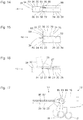
- Figure 1 shows a schematic representation of an endoscope 10 with a proximal end 12 and a distal end 14.
- a handling device 16 of the endoscope 10 forms its proximal end 12.
- the handling device 16 comprises an area with an enlarged cross section, in which electronic, optoelectronic, electro-optical, optical and other assemblies can be arranged. With its enlarged cross section, the handling device 16 can simplify manual gripping, holding and guiding the endoscope 10 and / or enable attachment to a tripod or to a manually or motor-adjustable arm (in the latter case often referred to as a robot arm).
- one or more connectors for connecting the endoscope 10 to an electrical power source, a light source, a camera control unit (often referred to as CCU) or to other devices or instruments can be provided by corresponding lines.
- the endoscope 10 further comprises a shaft 20, the proximal end 22 of which is connected to the handling device 16 or merges into it.
- a distal end 23 of the shaft 20 is located near the distal end 14 of the endoscope.
- the shaft 20 is straight and rigid.
- the lateral surface 26 of the shaft 20 represents a section of the lateral surface of a cylinder, in particular a circular cylinder.
- the longitudinal axis 28 of the shaft 20 is the axis of symmetry of this circular cylinder on which the centroids of all cross sections of the shaft 20 lie.
- the shaft can be partially or completely curved or flexible and thus can be curved.
- the longitudinal axis 28 of the shaft 20 in the following always means the longitudinal axis of the shaft 20 near its distal end 23.
- the shaft 20 can alternatively have non-circular cross sections.
- the longitudinal axis is in particular the line on which the centroids of the cross sections of the shaft lie.
- the shaft 20 has at its distal end 23 an end face 24 which, in the example shown, is flat and orthogonal to the longitudinal axis 28 of the shaft 20.
- the end face 24 at the distal end 23 of the shaft 20 can be curved and / or inclined relative to the longitudinal axis 28 of the shaft 20.
- the endoscope 10 furthermore has a movable component 30, which can be moved by an in Figure 1 Joint, not shown, is pivotally connected to the distal end 23 of the shaft 20 and is pivotable relative to the distal end 23 of the shaft 20.
- the joint defines a pivot axis 38 orthogonal to the plane of the drawing Figure 1 around which the movable component 30 is pivotable relative to the distal end 23 of the shaft 20.
- the joint can be a form-fitting joint with a shaft or an axle journal and a corresponding bearing or a solid body joint.
- the joint can be designed as a coupling gear, in which a pivoting movement is accompanied by a translational movement, similar to that known from concealed hinges in furniture construction.
- the pivot axis 38 lies on or near the edges of the end face 24 on the distal end 23 of the shaft 20 and the first end face 32 of the movable component 30.
- the movable component 30 is within one relative to the distal end 23 of the shaft 20 predetermined angular range between the in Figure 1 shown first configuration and one in Figure 2 shown second configuration pivotable.
- the movable component 30 is arranged distal of the distal end 23 of the shaft 20.
- the movable component 30 essentially has the shape of a short circular cylinder with a first end surface 32, a second end surface 34 and a lateral surface 36.
- the end faces 32, 34 of the movable component 30 are flat and parallel or substantially parallel to one another and orthogonal or substantially orthogonal to the lateral surface 36 in the example shown.
- the cross section of the movable component 30 essentially corresponds to the cross section of the shaft 20.
- the lateral surface 36 of the movable component 30 forms a straight and essentially smooth and essentially gap-free extension of the lateral surface 26 of the shaft 20.
- the shaft 20 can be through a trocar sleeve or through another opening with a cross-section that does not have to be, or does not have to be substantially larger than, the cross-section of the shaft 20 and the movable component 30, is introduced into a cavity to be viewed or examined.
- a first optical device 50 of the endoscope 10 is arranged at the distal end 23 of the shaft 20.
- the first optical device 50 is arranged immediately proximal to the end face 24 at the distal end 23 of the shaft 20 and adjoins the end face 24.
- a light entry surface 56 of the first optical device 50 is part of the end face 24 at the distal end 23 of the shaft 20.
- the first optical device 50 comprises, in particular, a lens or another imaging device for generating a real image. Furthermore, the first optical device 50 can have one or more image sensors for detecting the image generated by the lens or the other imaging device of the first optical device 50. Alternatively, a relay lens system or an ordered bundle of optical fibers or another image transmission device can be arranged in the shaft 20 in order to transmit the real image generated by the lens or the other imaging device of the first optical device 50 to the proximal end 12 of the endoscope 10.
- the first optical device 50 can comprise one or more light-emitting diodes or other light sources for generating illuminating light and / or a light exit surface of a light guide for transmitting illuminating light.
- One or more light exit surfaces of the light source or of the light sources or of the light guide or the light guide can likewise be part of the end face 24 at the distal end 23 of the shaft 20.
- a second optical device 60 is arranged in the movable component 30 and immediately adjacent to its first end face 32.
- One or more light entry surfaces 66 of the second optical device 60 are part of the first end surface 32 of the movable component 30.
- the second optical device 60 in particular comprises a lens or another imaging device for generating a real image and one or more image sensors for detecting the real image generated by the lens or the other imaging device.
- the second optical device 60 can comprise one or more light-emitting diodes or other light sources for generating illuminating light and / or one or more light exit surfaces of light guides for transmitting illuminating light.
- One or more light exit surfaces of the light source or of the light sources or of the light guide or the light guides can likewise be part of the first end face 32 of the movable component 30.
- a third optical device 70 is arranged in the movable component 30 directly adjacent to the second end face 34 of the movable component 30.
- One or more light entry surfaces 76 of the third optical device 70 are part of the second end surface 34 of the movable component 30.
- the third optical device 70 comprises in particular a lens or another imaging device for generating a real image and one or more image sensors for capturing the real image generated by the lens or other imaging device.
- the third optical device 70 can comprise one or more light-emitting diodes or other light sources for generating illuminating light and / or one or more light exit surfaces of light guides for transmitting illuminating light.
- One or more light exit surfaces of the light source or of the light sources or of the light guide or the light guide can likewise be part of the second end face 34 of the movable component 30.
- the end face 24 at the distal end 23 of the shaft 20 and the end faces 32, 34 of the movable component 30 are each flat or substantially flat.
- the end face 24 at the distal end 23 of the shaft 20 is orthogonal or substantially orthogonal to the longitudinal axis 28 of the shaft 20.
- the end faces 32, 34 of the movable component 30 are parallel to one another and at the in FIG Figure 1
- the configuration shown is parallel to the end face 24 at the distal end 23 of the shaft 20 and orthogonal to the longitudinal axis 28 of the shaft 20.
- the first end face 32 of the movable component 30 lies directly or partially or completely against the distal end 23 of the shaft 20 directly opposite the end face 24.
- the first optical device 50 at the distal end 23 of the shaft 20 and the second optical device 60 in the movable component 30 therefore have in FIG Figure 1 shown configuration no function and are particularly deactivated.
- the third optical device 70 has an optical axis 78, which is defined in particular by the objective or the other imaging device of the third optical device 70.
- the optical axis 78 in particular simultaneously represents the viewing direction of the third optical device 70.
- the field of vision of the third optical device 70 is also indicated by dashed lines. Objects that lie within this field of view of the third optical device 70 are in particular illuminated and detected by the third optical device.
- the third optical device 70 enables so especially in the in Figure 1 shown configuration of the endoscope 10 an insertion of the distal end 14 of the endoscope 10 into a cavity under optical control.
- Figure 2 shows a further schematic illustration of the endoscope 10 Figure 1 .
- the type of representation, in particular the orientation of the drawing plane, corresponds to that of Figure 1 ,
- FIG. 2 A second configuration of the endoscope 10 is shown, which differs from that in FIG Figure 1
- First configuration shown differs in that the movable component 30 is pivoted about an angle of approximately 180 degrees about the pivot axis 38.
- the movable component 30 is therefore no longer arranged distal of the distal end 23 of the shaft 20, but next to the distal end 23 of the shaft 20.
- the lateral surface 36 of the movable component 30 lies linearly against the lateral surface 26 of the shaft 20 or is only slightly spaced therefrom along a straight line.
- the second configuration shown shows that the end face 24 at the distal end 23 of the shaft 20 with the light entry face 56 of the first optical device 50 on the one hand and the first end face 32 of the movable component 30 with the light entry face 66 of the second optical device 60 on the other hand are arranged next to one another in one plane.
- the optical axis 58 of the first optical device 50 and the optical axis 68 of the second optical device 60 are parallel or substantially parallel to one another. If both the first optical device 50 and the second optical device 60 are each provided and designed for capturing an image, in FIG Figure 2 shown second configuration of the endoscope 10, a stereo image.
- the viewing direction of the third optical device 70 is oriented proximally. This can simplify orientation within a cavity.
- the third optical device 70 by means of the third optical device 70, the surroundings of an opening through which the shaft 20 of the endoscope 10 in protrudes into a cavity.
- the third optical device 70 in FIG Figure 2 shown configuration can be deactivated or switched off.
- Figure 3 shows a further schematic representation of the using the Figures 1 and 2 Endoscope 10 shown in a further configuration, which is based on the Figure 2 configuration shown is similar.
- the type of representation, especially the drawing level of the Figure 3 corresponds to that of Figures 1 and 2 ,
- the configuration shown differs from that shown in the Figure 2 shown configuration in particular in that the movable component 30 based on the Figure 1 first configuration shown is pivoted about an angle that is less than 180 degrees about the pivot axis 38.
- the optical axes 68, 78 of the second optical device 60 and the third optical device 70 in the movable component 30 are therefore not parallel to the longitudinal axis 28 of the shaft 20 and to the optical axis 58 of the first optical device 50 at the distal end 23 of the Shaft 20. Instead, the optical axis 58 of the first optical device at the distal end 23 of the shaft 20 on the one hand and the optical axis 68 of the second optical device 60 in the movable component 30 on the other hand intersect at an intersection. In a stereo image, the images of objects at the intersection of the optical axes 58, 68 and in an area (often ideally referred to as the zero plane) that contains this intersection do not show any disparity.
- the shaft 20 at its distal end 23 and / or the component 30 can be wedge-shaped, so that in the Figure 3 Relative orientation of the optical axes 58, 68 shown, the movable component 30 nevertheless abuts the shaft 20 in a linear or flat manner.
- the optical axis 58 of the first optical device 50 at the distal end 23 of the shaft 20 with respect to the longitudinal axis 28 of the shaft 20 and / or the optical axis 68 of the second optical device 60 in the movable component 30 with respect to the axis of symmetry of the lateral surface 36 of the movable component 30 may be inclined.
- the light entry surface 56 of the first optical device 50 at the distal end 23 of the shaft 20 with respect to the longitudinal axis 28 of the shaft 20 and / or the light entry surface 66 of the second optical device 60 with respect to the axis of symmetry of the outer surface 36 of the movable component 30 can be tilted ,
- Figure 4 shows a further schematic representation of the using the Figures 1 to 3 Endoscope 10 shown in a further configuration.
- the type of representation, especially the drawing level of the Figure 4 corresponds to that of Figures 1 to 3 ,
- the configuration shown differs from that shown using the Figures 2 and 3 Configurations shown in that the movable member 30 assumes a different angular position relative to the shaft 20.
- the angle between the optical axis 68 of the second optical device 60 in the movable component 30 and the optical axis 58 of the first optical device 50 at the distal end 23 of the shaft 20 is greater than that with reference to FIG Figure 3 shown configuration. Therefore, the distance of the intersection of the optical axes 58, 68 from the distal end 14 of the endoscope 10 is in the in Figure 4 shown configuration smaller than in the case of the Figure 3 shown configuration.
- the position of the point of intersection of the optical axes 58, 68 and thus the area recorded without disparity in the stereo image (“zero plane”) can be changed.
- Figure 5 shows a further schematic representation of the using the Figures 1 to 4 shown endoscope in a further configuration.
- the type of representation, especially the drawing level of the Figure 5 corresponds to that of Figures 1 to 4 ,
- the configuration shown differs from that shown using the Figures 1 to 4 shown configurations in that the angular position of the movable member 30 relative to the shaft 20 in the in Figure 5 shown configuration between the angular positions in the case of the Figures 1 and 4 configurations shown.
- the angle between the movable component 30 and the shaft 20 is thus even greater than that with reference to FIG Figure 4 shown configuration.
- the angle between the optical axis 58 of the first optical device 50 at the distal end 23 of the shaft 20 and the optical axis 68 of the second optical device 60 in the movable component 30 is also greater than that in the case of Figure 4 shown configuration.
- the distance of the intersection of the optical axes 58, 68 from the distal end 14 of the endoscope 10 is very small in relation to the length of the base, ie the distance from the center of the light entry surfaces 56, 66 of the first optical device 50 and the second optical device 60 Therefore, a consideration of one by means of the optical devices 50, 60 in the in Figure 5 configuration shown captured stereo image uncomfortable to painful or would no longer lead to a three-dimensional impression.
- the configuration shown can enable a simultaneous detection of an enlarged solid angle range.
- an image generated by the first optical device 50 at the distal end 23 of the shaft 20 and an image generated by the second optical device 60 in the movable component 30 can be joined together.
- the viewing direction 68 of the second optical device 60 and the viewing direction 78 of the third optical device are not completely orthogonal to the longitudinal axis 28 of the shaft 20.
- the viewing direction of the second optical device 60 is oriented somewhat more distally
- the viewing direction the third optical device 70 is oriented somewhat more proximally. Therefore, the annular areas, which can be detected in the movable component 30 on the one hand by means of the second optical device 60 and on the other hand by means of the third optical device 70 when the endoscope 10 rotates about the longitudinal axis 28 of the shaft 20, overlap only slightly. Conversely, this means that by rotating the endoscope 10 about the longitudinal axis 28 of the shaft 20 in the in Figure 5 shown configuration, a large contiguous area can be captured.
- Figure 6 shows a schematic representation of a variant of the based on the Figures 1 to 5 illustrated endoscope.
- the type of representation, in particular the plane of the drawing in FIG. 6 corresponds to that of FIG Figures 1 to 5 ,
- This in Figure 6 The endoscope shown is similar in some features, properties and functions to that based on the Figures 1 to 5 illustrated endoscope.
- Endoscope 10 shown differs from that based on FIG Figures 1 to 5 Endoscope shown in particular in that it has not only one movable component, but two movable components 30, 40.
- the first movable component 30 is articulated and mechanically connected to the distal end 23 of the shaft 20 about a first pivot axis 38 relative to the distal end 23 of the shaft 20.
- the second movable component 40 is articulated and pivotably connected to the first movable component 30 about a second pivot axis 48 relative to the first movable component 30.
- the first configuration shown are the first movable component 30 - similar to the one based on FIG Figure 1 shown configuration - distal to the distal end 23 of the shaft 20 and the second movable member 40 distal to the first movable member 30.
- the first movable component 30 and the second movable component 40 do not protrude, or do not protrude significantly, from the one that continues distally Shell surface 26 of the shaft 20 also.
- the cross sections of the shaft 20, the first movable component 30 and the second movable component 40 are the same or substantially the same.
- the lateral surface 26 of the shaft 20, the lateral surface 36 of the first movable component 30 and the lateral surface 46 of the second movable component 40 start - from small gaps between the distal end of the shaft 23 and the first movable component 30 and between the first movable component 30 and apart from the second movable component 40 - smoothly into one another.
- the shaft 20 with the movable components 30, 40 can be inserted into a cavity through an opening, the cross section of which does not have to be, or does not have to be, substantially larger than the individual cross sections of the shaft 20 and the movable components 30, 40.
- the second movable member 40 can be pivoted relative to the first movable member 30 about the second pivot axis 48 and / or the first movable member 30 relative to the distal end 23 of the shaft 20 about the first pivot axis 38.
- the pivoting movement of the second movable component 40 relative to the first movable component 30 about the second pivot axis 48 can be independent of the pivoting movement of the first movable component 30 relative to the distal end 23 of the shaft 20 about the first pivot axis 38.
- a coupling can be provided such that a pivoting movement of the first movable component 30 relative to the distal end 23 of the shaft 20 about the first pivot axis 38 with a pivoting movement of the second movable component 40 relative to the first movable component 30 about the second pivot axis 48 accompanied.
- a contact surface 27 is provided on the shaft 20.
- a contact surface 47 corresponding to the contact surface 27 on the shaft 20 is provided on the lateral surface 46 of the second movable component 40.
- Endoscope 10 shown differs from that based on FIG Figures 1 to 5 illustrated endoscope further in that a second optical device 60 and a third optical device 70 are not on end faces of the first movable component 30 or the second movable component 40 are arranged. Rather, the second optical device 60 is arranged on the lateral surface 36 of the first movable component 30, and the third optical device 70 is arranged on the lateral surface 46 of the second movable component 40.
- the configuration of the endoscope 10 shown are viewing directions of the second optical device 60 and the third optical device 70 orthogonal or substantially orthogonal to the longitudinal axis 28 of the shaft 20.
- Figure 7 shows a further schematic illustration of the endoscope 10 Figure 6 ,
- the type of representation, especially the drawing level of the Figure 7 corresponds to that of Figures 1 to 6
- the endoscope 10 is in Figure 7 shown in a second configuration, which differs from that based on the Figure 6 shown first configuration differs.
- the second configuration of the endoscope 10 shown is the second movable component 40 relative to the first movable component 30 by a predetermined angle (for example 60 degrees) about the second pivot axis 48 and the first movable component 30 relative to the distal end 23 of the shaft 20 by one predetermined angle (for example 150 degrees) pivoted about the first pivot axis 38.
- the contact surface 47 bears on the second movable component 40 on the corresponding contact surface 27 on the shaft 20. This can enable or simplify the transfer of waste heat, which is released in the second movable component 40 in the third optical device 70, for example, to the shaft 20.
- the optical devices 50, 60, 70 and their fields of view are designed in this way and the movable components 30, 40 in the case of FIGS Figure 7
- the second configuration shown is arranged and oriented such that the fields of view of the optical devices 50, 60, 70 overlap one another at the working distance (outside the area shown in FIG. 7). Therefore in the in Figure 7 shown second configuration with the optical devices 50, 60, 70 together a wide-angle view of the surroundings of the distal end 14 of the endoscope 10 are captured. With a rotation of the endoscope 10 about the longitudinal axis 28 of the shaft 20 the inner surface of a cavity can be captured almost completely. In the Figure 7 indicated fields of view, only a small area around the shaft 20 of the endoscope 10 protrudes into the cavity, cannot be detected.
- Figure 8 shows a schematic representation of a section through a distal end 14 of a further variant of the on the basis of FIG Figures 1 to 5 illustrated endoscope.
- the cutting plane of the Figure 8 is parallel to the drawing levels of the Figures 1 to 7 .
- the distal end 14 of the endoscope is in Figure 9 enlarged compared to the representations in the Figures 1 to 7 shown.
- Figure 8 is based on the Figure 1 shown configuration shown.
- each of the optical devices 50, 60, 70 comprises an objective 52, 62, 72 and an image sensor 54, 64, 74.
- each optical device 50, 60, 70 can have a plurality of image sensors 52, 62, 72 for different wavelength ranges and dichroically reflecting surfaces, so that only light within a predetermined wavelength range falls on each image sensor 54, 64, 74.
- Each optical device 50, 60, 70 can furthermore have a plurality of lenses 52, 62, 72 and a plurality of image sensors 54, 64, 74 in order to acquire a stereo image or to acquire images in a plurality of different wavelength ranges.
- Each of the optical devices 50, 60, 70 may alternatively or additionally have one or more light-emitting diodes or other light sources for generating illuminating light and / or one or more light exit surfaces of light guides for transmitting illuminating light.
- optical devices at the distal end of the shaft and in the movable component can each be constructed similarly as here, for example, using the Figure 8 described.
- waste heat released in a movable component can be transmitted to the shaft via a flat mechanical contact.
- a heat pipe or another device for transferring heat can be provided in each case in order to transfer waste heat along the shaft to the proximal end of the endoscope.
- a thermally conductive elastic component 94 is provided, which connects the movable component 30 to the distal end 23 of the shaft 20 in a thermally conductive manner.
- the thermally conductive elastic component 94 is connected, in particular directly or via another thermally conductive component, indirectly to one or more heat sources of the movable component 30, for example — as in FIG Figure 8 indicated - with the second optical device 60, optionally also with the third optical device 70.
- the other end of the thermally conductive elastic component 94 is connected, for example, to a distal end of a heat pipe 21 or another heat transfer device in the shaft 20.
- the thermally conductive elastic component 94 comprises, in particular, a fabric or braid or bundle of thin and elastic thermally conductive fibers.
- the thermally conductive elastic member 94 has, for example, copper, silver, aluminum, gold, graphite, graphene, diamond, carbon nanotubes, silicon carbide, aluminum nitride or another material whose thermal conductivity is at least half the thermal conductivity of pure copper - i. H. is at least 200 W / Km -.
- the thermally conductive elastic component 94 is, in particular, a thermally conductive elastic component, as it is offered and sold commercially under the term "thermal strap".
- the thermally conductive elastic component 94 can be compared to heat transfer by means of contact surfaces which are in contact with one another, as is shown in FIG Figures 6 and 7 have the advantage of allowing waste heat to be dissipated from the movable component 30 in many different angular positions of the movable component 30 relative to the distal end 23 of the shaft 20.
- the heat pipe 21 in the shaft 20 can transfer the waste heat from the movable component 30 and optionally also waste heat from the first optical device 50 or another heat source at the distal end 23 of the shaft 20 to the proximal end 12 of the endoscope 10 (cf. Figures 1 to 7 ) enable.
- the thermally conductive elastic component 94 and the heat pipe 21 can lower the surface temperature of the endoscope at its distal end 14 and the thermal power introduced into the cavity to be examined by means of the endoscope.
- the thermally conductive elastic component 94 can simultaneously form the only mechanical connection of the movable component 30 to the distal end 23 of the shaft 20, similar to a solid-state joint.
- another joint can be provided.
- Figure 9 shows two schematic representations of the distal end 14 of a further variant of the on the basis of FIG Figures 1 to 5 illustrated endoscope.
- the distal end 14 of the endoscope is in Figure 9 enlarged compared to the representations in the Figures 1 to 7 shown, similar to in Figure 8 .
- the type of representation, in particular the drawing level is similar in Figure 9 left of those of Figures 1 to 7
- Figure 9 on the right the distal end 14 of the endoscope is shown in a distal view.
- the drawing level of the Figure 9 the right is therefore orthogonal to the plane of the drawing Figure 9 left and to the longitudinal axis 28 of the shaft 20.
- the endoscope, the distal end 14 in Figure 9 is similar in some features, properties and functions to that shown in Figures 1 to 5 and 8th shown endoscopes. The following are in particular features, properties and functions of the endoscope, the distal end 14 in Figure 9 is shown.
- Figure 9 is the movable component 30 in solid lines in its position, which is based on the Figure 2 corresponds to the second configuration of the endoscope shown.
- the movable component 30 On the left, the movable component 30 is also in its position, which is based on the Figure 1 corresponds to the illustrated first configuration of the endoscope, indicated in dashed lines.
- the endoscope, the distal end 14 in Figure 9 shown differs from that shown in Figures 1 to 8 Endoscopes shown in particular in that the shaft 20 near its distal end 23 has a first, concave contact surface 27 in a flat recess.
- the shape of the first contact surface 27 at the distal end 23 of the shaft 20 corresponds to the shape of a region of the lateral surface 36 of the movable component 30 provided as the second contact surface 37 on the movable component 30.
- the first contact surface 27 at the distal end 23 of the shaft 20 and the second contact surface 37 on the movable component 30 have corresponding curvatures, the first contact surface 27 on the distal end 23 of the shaft 20 being concave and the second contact surface 37 on the movable component 30 being convex.
- the second contact surface 37 lies flat on the movable component 30 on the first contact surface 27 on the distal end 23 of the shaft 20. This enables good heat transfer from the movable component 30 to the distal end 23 of the shaft 20.
- both contact surfaces 27, 37 each have the shape of a cutout from the outer surface of the same circular cylinder.
- the endoscope, the distal end 14 in Figure 9 shown differs from that shown in the Figures 1 to 5 Endoscope shown further characterized in that a heat pipe 21 is provided within the shaft 20 (and therefore only indicated in dashed lines), similar to that with reference to FIG Figure 8 illustrated endoscope.
- the distal end of the heat pipe 21 is in particular directly or indirectly connected to the first contact surface 27 on the distal end 23 of the shaft 20 by a thermally conductive component.
- the heat pipe 21 enables waste heat that is released in the movable component 30 to be dissipated, and optionally also the dissipation of waste heat from the first optical device 50 or another component at the distal end 23 of the shaft 20 to the proximal end of the endoscope.
- the endoscope, the distal end 14 in Figure 9 shown differs from that shown in Figures 1 to 8 Endoscopes shown further in that only a second optical device 60 is provided in the movable member 30.
- a sensor 81 is provided in the movable component 30, for example on the second end face 34 of the movable component 30.
- the sensor 81 is, for example, a sensor for detecting a pressure, a temperature, a pH value or another Concentration or a laser sensor for scanning or otherwise detecting the surroundings of the distal end 14 of the endoscope.
- Figure 10 shows a schematic representation of a distal end 14 of a further variant of the with reference to FIG Figures 1 to 5 illustrated endoscope.
- the type of representation in Figure 10 corresponds to that in Figure 9 .
- the endoscope, the distal end 14 in Figure 10 is similar in some features, properties and functions to that shown in Figures 1 to 9 Endoscopes shown, in particular that based on the Figure 9 illustrated endoscope.
- the following are in particular features, properties and functions of the endoscope, the distal end 14 in Figure 10 is shown, in which this differs from that with reference to Figure 9 shown endoscope differs.
- the endoscope, the distal end 14 in Figure 10 shown differs from that shown in Figure 9 Endoscope shown in particular in that both contact surfaces 27, 37 are each formed flat on the distal end 23 of the shaft 20 and on the movable component 30. This also enables large-area contact and a correspondingly good heat transfer from the movable component 30 to the distal end 23 of the shaft 20.
- Figure 11 shows a schematic representation of a distal end 14 of a further variant of the with reference to FIG Figures 1 to 5 illustrated endoscope.
- the type of representation corresponds to that in the Figures 9 and 10 each on the right.
- the drawing level of the Figure 11 is therefore orthogonal to the plane of the drawing Figures 1 to 8 and to the drawing levels of the Figures 9 and 10 left and orthogonal to the longitudinal axis of the shaft 20.
- the distal End 14 of the endoscope is in Figure 11 in the based on the Figures 2 shown second configuration of the endoscope.
- the endoscope, the distal end 14 in Figure 11 is similar in some features, properties and functions to that shown in FIG Figures 1 to 10 Endoscopes shown, in particular that based on the Figure 9 illustrated endoscope.
- the following are in particular features, properties and functions of the endoscope, the distal end 14 in Figure 11 is shown, in which this differs from that based on the Figure 9 shown endoscope differs, described.
- FIG 11 Endoscope shown differs from that shown on the Figure 9 Endoscope shown in particular in that two light entry surfaces 56 of two first optical devices 50 are provided side by side on the end face 24 at the distal end 23 of the shaft 20.
- the two first optical devices 50 at the distal end 23 of the shaft 20 are in particular identical in construction, that is to say they have identical properties apart from an unavoidable spread of parameters, and are provided for capturing a stereo image.
- the two first optical devices 50 can be provided and formed on the distal end 23 of the shaft 20 for acquiring images at different wavelengths or within different wavelength ranges.
- Figure 12 shows a schematic representation of a distal end 14 of a further variant of the with reference to FIG Figures 1 to 5 illustrated endoscope.
- the type of representation corresponds to that in the Figures 9 and 10 each on the right and the Figure 11 ,
- the distal end 14 of the endoscope is in Figure 12 in the based on the Figures 2 shown second configuration of the endoscope.
- the endoscope, the distal end 14 in Figure 12 is similar in some features, properties and functions to that shown in FIG Figures 1 to 11 shown endoscopes, in particular those based on Figures 9 to 11 shown endoscopes.
- the following are in particular features, properties and functions of the endoscope, its distal end 14 in Figure 12 is shown, in which this differs from that shown in the Figures 1 to 11 shown endoscopes differs.
- the endoscope, the distal end 14 in Figure 12 is shown differs, for example, from those based on Figures 9 and 11 Endoscopes shown in particular in that three second optical devices 60 are provided on the first end face 32 of the movable component 30.
- the three second optical devices 60 on the first end face 32 of the movable component 30 can be identical in construction, for example for capturing three images in the same wavelength range. In this case, two images captured by second optical devices 60 can be selected in each case in order to form a stereo image.
- the second optical devices 60 can be provided and formed on the first end face 32 of the movable component 30 for capturing images in different wavelength ranges.
- the second optical devices 60 can be provided on the first end face 32 of the movable component 30 for generating illuminating light of the same or different spectra.
- part of the second optical devices 60 can be provided and formed on the first end face 32 of the movable component 30 for acquiring images and another part for generating illuminating light.
- the endoscope, the distal end 14 in Figure 12 shown differs from that shown in Figures 9 and 11 Endoscopes shown further characterized in that the first contact surface 27 on the distal end 23 of the shaft 20 is convex and the second contact surface 37 on the movable component 30 is concave.
- Figure 13 shows a schematic representation of a distal end 14 of a further variant of the with reference to FIG Figures 1 to 5 illustrated endoscope.
- the type of representation corresponds to that in the Figures 9 and 10 each on the right and the Figures 11 and 12 ,
- the distal end 14 of the endoscope is in Figure 13 in the based on the Figures 2 shown second configuration of the endoscope.
- the endoscope, the distal end 14 in Figure 13 is similar in some features, properties and functions to that shown in FIG Figures 1 to 11 shown endoscopes.
- the following are in particular features, properties and functions of the endoscope, the distal end 14 in Figure 13 is shown, in which this differs from that shown in the Figures 1 to 12 shown endoscopes differs.
- the endoscope, the distal end 14 in Figure 13 shown differs from that shown in Figures 1 to 12 Endoscopes shown in particular in that a second optical device 60 and two third optical devices 70 are provided next to each other on the first end face 32 of the movable component 30.
- the second optical device 60 is provided and configured for capturing an image
- the third optical device 70 is provided and configured for generating illuminating light.
- the third optical devices 70 can be constructed identically or differently in order to provide illuminating light with different spectra.
- the endoscope, the distal end 14 in Figure 13 is shown differs from that based on Figures 1 to 12 Endoscopes shown further in that no optical device is provided on the distal end 23 of the shaft 20. Instead, the shaft 20 has a working channel 29 which ends in an opening in the end face 24 at the distal end 23 of the shaft 20. Fluids or solids can be conveyed through the working channel 29 and / or a medical instrument can be introduced into a cavity in which the distal end 14 of the endoscope is arranged.
- FIG. 1 to 7 Endoscopes shown can be the characteristics of the Figures 8 to 13 have shown endoscopes.
- the Figures 1 to 7 Endoscopes shown each have a heat pipe 21 or another heat conduction device in or on the shaft 20.
- the Figures 1 to 7 Endoscopes shown have elastic components for articulated mechanical and / or heat-conductive connection of the movable component or first movable component 30 with the distal end 23 of the shaft 20 and / or the movable components 30, 40 with each other.
- Figure 14 shows a schematic representation of a distal end 14 of a further variant of the with reference to FIG Figures 1 to 5 illustrated endoscope.
- the endoscope, the distal end 14 in Figure 14 is similar in some features, properties and functions to that shown in Figures 1 to 13 shown endoscopes. Features, properties and functions in particular are described below in which the endoscope, its distal end 14 in Figure 14 is shown, differing from the Figures 1 to 13 shown endoscopes differs.
- the endoscope, the distal end 14 in Figure 14 has a rack 88 and a gear 89.
- the rack 88 in particular within the shaft 20 and the gear 89, in particular at least partially arranged within the shaft 20 and the movable component 30 and therefore not visible or only partially visible from the outside, these are shown in FIG Figure 14 shown in full lines to make their function recognizable.
- the rack 88 extends in particular from the proximal end of the endoscope, where it can be directly or indirectly coupled to an operating device or a drive, to the distal end 23 of the shaft 20.
- the gear wheel 89 is directly or indirectly rigid with the movable component 30 connected and pivotable together with the movable member 30 about the predetermined pivot axis 38 of the movable member 30.
- the gear 89 can be coupled to the movable component 30 via a gear or in some other way.
- the rack 88 has - in particular only - near its distal end in the area of the gear 89 teeth which mesh with teeth of the gear 89.
- a translational movement of the rack 88 (in particular parallel to the longitudinal axis 28 of the shaft 20) is therefore accompanied by a pivoting movement of the movable component 30.
- the example shown is based on the Figure 1 shown and also in Figure 14 shown first configuration of the endoscope when the rack 88 is in an extremely proximal position.
- Figure 15 shows a further schematic representation of the distal end 14 of the with reference to FIG Figure 14 illustrated endoscope.
- Figure 15 is based on the Figure 2 shown second configuration of the endoscope. This second configuration is achieved if, starting from the in Figure 14 First configuration shown, the rack 88 in an extremely distal, in Figure 15 shown position is moved.
- Figure 16 shows a schematic representation of a distal end 14 of a further variant of the with reference to FIG Figures 1 to 5 illustrated endoscope.
- the type of representation in Figure 16 corresponds in particular to that of the Figures 14 and 15 .
- Some structures that are partially or completely arranged within the shaft 20 and / or the movable component 30 and are therefore not visible from the outside are shown in FIG Figure 16 nevertheless shown in solid lines.
- the endoscope, the distal end 14 in Figure 16 is similar in some features, properties and functions to that shown in FIG Figures 1 to 15 shown endoscopes.
- the following are in particular features, properties and functions of the endoscope, the distal end 14 in Figure 16 is shown, in which this differs from that shown in the Figures 14 and 15 shown endoscopes differs.
- the endoscope, the distal end 14 in Figure 16 is shown, for example, differs from that based on Figures 14 and 15 Endoscope shown in particular in that no rack and no gear are provided for moving the movable member 30. Instead, the endoscope has a first pull cable 86 and a second pull cable 87, the distal ends of which are connected to the movable component 30 at different locations.
- the movable component 30 and the pull cables 86, 87 are shown in FIG Figure 16 shown in two different positions. In solid lines, the movable component 30 and the pulling ropes 86, 87 are shown in positions that the on the basis of the Figure 1 correspond to the first configuration of the endoscope shown. In dashed lines, the movable component and the pulling cables 86, 87 are in positions between positions based on the Figure 1 shown first configuration and based on the Figures 2 to 5 shown second and further configurations shown.
- a pulling force in the first pulling cable 86 pivots the movable component 30 about the pivot axis 38 to the position which is based on the Figure 1 corresponds to the first configuration shown and in Figure 16 is shown in solid lines.
- a pulling force in the second pulling cable 87 swivels the movable component 30 over that in FIG Figure 16 Position shown in dashed lines up to the position which is based on the Figure 2 shown second configuration corresponds.
- Figure 17 shows a schematic representation of the proximal end 12 of the endoscope 10, the distal end 14 of which is shown in FIG Figure 16 is shown. Also in Figure 17 some structures that are partially or completely arranged within the endoscope 10 and are therefore not or only partially visible from the outside are shown in solid lines. Otherwise the representation corresponds to Figure 17 , especially the drawing level, the representation in the Figures 1 to 7 ,
- the endoscope 10 has at its proximal end 12 a first grip part 17 and a second grip part 18, which can be moved relative to one another.
- the first handle part 17 is mechanically rigid with the rest of the handling device 16 and thus also indirectly connected to the proximal end 22 of the shaft 20.
- the second handle part 18 is via a shaft 83 which has a pivot axis orthogonal to the plane of the drawing Figure 17 defined, pivotally connected to the handling device 16.
- a first cam plate 84 and a second cam plate 85 are arranged in the handling device 16, which are rigid via the shaft 83 (or alternatively and deviating from the illustration in FIG Figure 17 : via a gear) are coupled to the second handle part 18.
- a proximal end of the first traction cable 86 is connected to the first pulley 84, a proximal end of the second traction cable 87 is connected to the second pulley 85.
- the sheaves 84, 85 can each have an almost arbitrary shape, in particular deviating from a circular shape.
- the second handle part 18, the pulleys 84, 85 and the traction cables 86, 87 are each shown in solid lines in a first position and in dashed lines in a second position.
- the pull cables 86, 87 couple the second handle part 18 to the movable component 30 at the distal end 23 of the shaft 20 (cf. Figure 16 ) that a pivoting movement of the second grip part 18 relative to the first grip part 17 is accompanied by a pivoting movement of the movable component 30 about the pivot axis 38.
- movable handle part 18 for example a rotary wheel, a slide or a motor drive can be provided.
- Figure 18 shows schematic representations of a distal end 14 of a further variant of the with reference to FIG Figures 1 to 5 illustrated endoscope.
- the type of display, in particular the drawing levels, largely corresponds to that of Figures 9 and 10 ,
- the drawing level is the Figure 18 left parallel to a longitudinal axis 28 of the shaft 20 and the plane of the drawing in Figure 18 right orthogonal to the plane of the drawing in figure 18 on the left and orthogonal to the longitudinal axis 28 of the shaft 20.
- Figure 18 on the left shows a view from the side, in contrast to which an outer shaft 90 is shown in section along a plane which contains the longitudinal axis 28 of the shaft 20 and is parallel to the plane of the drawing.
- the distal end 14 of the endoscope is shown in a distal view.
- the endoscope, the distal end 14 in Figure 18 is similar in some features, properties and functions to that shown in FIG Figures 1 to 13 shown endoscopes.
- the endoscope, the distal end 14 in Figure 18 an elastic component 94, which mechanically connects the movable component 30 to the distal end 23 of the shaft 20.
- the elastic component 94 is designed such that the movable component 30 relative to the distal end 23 of the shaft 20 exclusively or almost exclusively about a pivot axis orthogonal to the plane of the drawing Figure 18 can pivot left.
- the elastic component 94 is designed in particular as a wide, thin and short band, the width being in the direction orthogonal to the plane of the drawing Figure 18 left, the length in the direction orthogonal to the plane of the drawing Figure 18 right and the thickness is measured in the third direction orthogonal thereto.
- the endoscope the distal end 14 in Figure 18 is also shown, has an outer shaft 90 which encloses a cavity 92 in the form of a jacket.
- a cavity 92 enclosed by the outer shaft 90 in the form of a jacket in FIG Figure 18 illustrated first configuration of the shaft 20 and at least a portion of the movable member 30.
- the cross section of the cavity 92 enclosed by the outer shaft 90 and the cross sections of the shaft 20 and the movable component 30 are coordinated with one another in such a way that the shaft 20 and the movable component 30 are guided in the outer shaft 90 with little play and with little friction.
- the movable component 30 is arranged distal of the distal end 23 of the shaft 20.
- the shaft 20 and at least part of the movable component 30 are arranged within the cavity 92 enclosed by the outer shaft 90.
- position of the outer shaft 90 holds the movable member 30 in the position corresponding to the first configuration.
- Figure 19 shows a further schematic representation of the distal end 14 of the with reference to FIG Figure 18 illustrated endoscope.
- FIG 19 is based on the Figure 2 shown second configuration of the endoscope.
- the outer shaft 90 occupies a proximal position relative to the shaft 20 and the movable component 30, in which the movable component 30 and a distal region of the shaft 20 outside the cavity 92 enclosed by the outer shaft 90 and the movable component 30 next to the distal one End 23 of the shaft 20 are arranged.
- the movable member 30 takes the in Figure 19 shown position because an elastic restoring force of the elastic member 94 moves the movable member 30 into the in Figure 19 position shown pivots.
- the elastic energy of the elastic member 94 is that in FIG Figure 19 second configuration shown less than in the in Figure 18 first configuration shown.
Landscapes
- Health & Medical Sciences (AREA)
- Life Sciences & Earth Sciences (AREA)
- Surgery (AREA)
- Physics & Mathematics (AREA)
- Optics & Photonics (AREA)
- General Health & Medical Sciences (AREA)
- Engineering & Computer Science (AREA)
- Radiology & Medical Imaging (AREA)
- Animal Behavior & Ethology (AREA)
- Biophysics (AREA)
- Biomedical Technology (AREA)
- Heart & Thoracic Surgery (AREA)
- Medical Informatics (AREA)
- Molecular Biology (AREA)
- Pathology (AREA)
- Nuclear Medicine, Radiotherapy & Molecular Imaging (AREA)
- Public Health (AREA)
- Veterinary Medicine (AREA)
- Astronomy & Astrophysics (AREA)
- General Physics & Mathematics (AREA)
- Multimedia (AREA)
- Endoscopes (AREA)
Applications Claiming Priority (1)
| Application Number | Priority Date | Filing Date | Title |
|---|---|---|---|
| DE102018120696.8A DE102018120696A1 (de) | 2018-08-24 | 2018-08-24 | Endoskop mit einem bewegbaren Bauteil |
Publications (2)
| Publication Number | Publication Date |
|---|---|
| EP3613331A1 true EP3613331A1 (fr) | 2020-02-26 |
| EP3613331B1 EP3613331B1 (fr) | 2023-04-26 |
Family
ID=67551144
Family Applications (1)
| Application Number | Title | Priority Date | Filing Date |
|---|---|---|---|
| EP19190235.2A Active EP3613331B1 (fr) | 2018-08-24 | 2019-08-06 | Endoscope doté d'un composant mobile |
Country Status (2)
| Country | Link |
|---|---|
| EP (1) | EP3613331B1 (fr) |
| DE (1) | DE102018120696A1 (fr) |
Cited By (2)
| Publication number | Priority date | Publication date | Assignee | Title |
|---|---|---|---|---|
| CN115868905A (zh) * | 2022-12-22 | 2023-03-31 | 湖南省华芯医疗器械有限公司 | 前端组件、插入部及内窥镜 |
| DE102023129188B3 (de) | 2023-10-24 | 2025-02-06 | Karl Storz Se & Co. Kg | Endoskopvorrichtung zur Bilderfassung |
Families Citing this family (1)
| Publication number | Priority date | Publication date | Assignee | Title |
|---|---|---|---|---|
| DE102023121124A1 (de) * | 2023-08-08 | 2025-02-13 | Karl Storz Se & Co. Kg | Endoskopvorrichtung, endoskopisches System und endoskopisches Bildgebungsverfahren |
Citations (11)
| Publication number | Priority date | Publication date | Assignee | Title |
|---|---|---|---|---|
| DE3415771A1 (de) | 1983-04-29 | 1984-10-31 | Warner Lambert Technologies, Inc., Southbridge, Mass. | Endoskop und verfahren zum abbiegen des distalen endes eines endoskopes |
| DE3921233C2 (fr) | 1989-06-28 | 1992-01-16 | Karl Storz Gmbh & Co, 7200 Tuttlingen, De | |
| US5381784A (en) * | 1992-09-30 | 1995-01-17 | Adair; Edwin L. | Stereoscopic endoscope |
| EP0774231A1 (fr) * | 1995-11-20 | 1997-05-21 | Wilson Greatbatch Ltd. | Endoscope électronique à vidéo alimenté par une batterie |
| DE4241938B4 (de) | 1992-12-11 | 2004-11-04 | Karl Storz Gmbh & Co. Kg | Endoskop insbesondere mit Stereo-Seitblickoptik |
| US20060252994A1 (en) * | 2005-05-06 | 2006-11-09 | Nitesh Ratnakar | Next Generation Colonoscope |
| DE102005045729A1 (de) | 2005-09-23 | 2007-03-29 | Karl Storz Gmbh & Co. Kg | Beleuchtungssystem für endoskopische Untersuchungen |
| US20080275298A1 (en) * | 2004-10-11 | 2008-11-06 | Novation Science, Llc | Dual View Endoscope |
| EP2394567A1 (fr) | 2010-06-11 | 2011-12-14 | Karl Storz GmbH & Co. KG | Endoscope |
| US20120232346A1 (en) * | 2009-11-20 | 2012-09-13 | Tohoku University | Insertion device and endoscope |
| US20140180001A1 (en) * | 2012-12-20 | 2014-06-26 | avanteramedical GmBH | Endoscope Comprising a System with Multiple Cameras for Use in Minimal-Invasive Surgery |
Family Cites Families (1)
| Publication number | Priority date | Publication date | Assignee | Title |
|---|---|---|---|---|
| US8556806B2 (en) * | 2004-09-24 | 2013-10-15 | Vivid Medical, Inc. | Wavelength multiplexing endoscope |
-
2018
- 2018-08-24 DE DE102018120696.8A patent/DE102018120696A1/de active Pending
-
2019
- 2019-08-06 EP EP19190235.2A patent/EP3613331B1/fr active Active
Patent Citations (11)
| Publication number | Priority date | Publication date | Assignee | Title |
|---|---|---|---|---|
| DE3415771A1 (de) | 1983-04-29 | 1984-10-31 | Warner Lambert Technologies, Inc., Southbridge, Mass. | Endoskop und verfahren zum abbiegen des distalen endes eines endoskopes |
| DE3921233C2 (fr) | 1989-06-28 | 1992-01-16 | Karl Storz Gmbh & Co, 7200 Tuttlingen, De | |
| US5381784A (en) * | 1992-09-30 | 1995-01-17 | Adair; Edwin L. | Stereoscopic endoscope |
| DE4241938B4 (de) | 1992-12-11 | 2004-11-04 | Karl Storz Gmbh & Co. Kg | Endoskop insbesondere mit Stereo-Seitblickoptik |
| EP0774231A1 (fr) * | 1995-11-20 | 1997-05-21 | Wilson Greatbatch Ltd. | Endoscope électronique à vidéo alimenté par une batterie |
| US20080275298A1 (en) * | 2004-10-11 | 2008-11-06 | Novation Science, Llc | Dual View Endoscope |
| US20060252994A1 (en) * | 2005-05-06 | 2006-11-09 | Nitesh Ratnakar | Next Generation Colonoscope |
| DE102005045729A1 (de) | 2005-09-23 | 2007-03-29 | Karl Storz Gmbh & Co. Kg | Beleuchtungssystem für endoskopische Untersuchungen |
| US20120232346A1 (en) * | 2009-11-20 | 2012-09-13 | Tohoku University | Insertion device and endoscope |
| EP2394567A1 (fr) | 2010-06-11 | 2011-12-14 | Karl Storz GmbH & Co. KG | Endoscope |
| US20140180001A1 (en) * | 2012-12-20 | 2014-06-26 | avanteramedical GmBH | Endoscope Comprising a System with Multiple Cameras for Use in Minimal-Invasive Surgery |
Cited By (4)
| Publication number | Priority date | Publication date | Assignee | Title |
|---|---|---|---|---|
| CN115868905A (zh) * | 2022-12-22 | 2023-03-31 | 湖南省华芯医疗器械有限公司 | 前端组件、插入部及内窥镜 |
| CN115868905B (zh) * | 2022-12-22 | 2024-05-14 | 湖南省华芯医疗器械有限公司 | 前端组件、插入部及内窥镜 |
| DE102023129188B3 (de) | 2023-10-24 | 2025-02-06 | Karl Storz Se & Co. Kg | Endoskopvorrichtung zur Bilderfassung |
| WO2025087649A1 (fr) | 2023-10-24 | 2025-05-01 | Karl Storz Se & Co. Kg | Dispositif d'endoscope pour capture d'images |
Also Published As
| Publication number | Publication date |
|---|---|
| DE102018120696A1 (de) | 2020-02-27 |
| EP3613331B1 (fr) | 2023-04-26 |
Similar Documents
| Publication | Publication Date | Title |
|---|---|---|
| DE68910988T2 (de) | Kupplungseinrichtung für eine endoskopische Fernsehkamera. | |
| EP1767139B1 (fr) | Systeme d'eclairage pour endoscopie | |
| DE60006763T2 (de) | Endoskop mit einem Linsenantriebsmechanismus | |
| EP3922162B1 (fr) | Endoscope pourvu de dispositif pivotant de capture d'image | |
| EP2392248B1 (fr) | Enveloppe pour dispositif de transfert d'images et endoscope l'utilisant | |
| DE10348188B4 (de) | Ultraschall-Endoskop | |
| DE3921233C2 (fr) | ||
| EP1600804A1 (fr) | Dispositif visuel pour endoscopes | |
| DE202009017097U1 (de) | Endkoskop insbesondere für die minimal-invasive Chirurgie an der Wirbelsäule | |
| EP2850996B1 (fr) | Dispositif de réception d'une image d'un champ de l'objet sur un corps humain ou d'animal | |
| EP3613331B1 (fr) | Endoscope doté d'un composant mobile | |
| EP2735259B1 (fr) | Endoscope à direction d'observation réglable | |
| DE102017107106A1 (de) | Endoskop mit weitwinkeloptik und arbeitskanal | |
| DE102013213232B4 (de) | Endoskop mit seitlicher Blickrichtung | |
| DE112016000132B4 (de) | Ultraschallendoskop | |
| DE102010028147A1 (de) | Endoskop mit variabler Blickrichtung | |
| EP2911571B1 (fr) | Endoscope à illumination latérale, utilisation et procédé | |
| EP3720333A1 (fr) | Endoscope doté d'une partie de préhension pivotante | |
| DE10046444B4 (de) | Chirurgische Schaftoptik | |
| DE102023130857B3 (de) | Filterwechselvorrichtung für eine endoskopische Kamera, Kamerakopf für ein Endoskop und Nachrüstsatz zum Nachrüsten eines Kamerakopfes und/oder eines Endoskops | |
| DE102024110878B3 (de) | Filterwechselvorrichtung für eine endoskopische Kamera, Kamerakopf für ein Endoskop und Nachrüstsatz zum Nachrüsten eines Kamerakopfes und/oder eines Endoskops | |
| DE10359337B4 (de) | Endoskop | |
| EP1469335A1 (fr) | Endoscope | |
| DE102024138870B3 (de) | Endoskopvorrichtung und Endoskop mit einer Endoskopvorrichtung | |
| DE10020716B4 (de) | Dermatologie-Bildaufnahmesystem |
Legal Events
| Date | Code | Title | Description |
|---|---|---|---|
| PUAI | Public reference made under article 153(3) epc to a published international application that has entered the european phase |
Free format text: ORIGINAL CODE: 0009012 |
|
| STAA | Information on the status of an ep patent application or granted ep patent |
Free format text: STATUS: THE APPLICATION HAS BEEN PUBLISHED |
|
| AK | Designated contracting states |
Kind code of ref document: A1 Designated state(s): AL AT BE BG CH CY CZ DE DK EE ES FI FR GB GR HR HU IE IS IT LI LT LU LV MC MK MT NL NO PL PT RO RS SE SI SK SM TR |
|
| AX | Request for extension of the european patent |
Extension state: BA ME |
|
| STAA | Information on the status of an ep patent application or granted ep patent |
Free format text: STATUS: REQUEST FOR EXAMINATION WAS MADE |
|
| 17P | Request for examination filed |
Effective date: 20201113 |
|
| RBV | Designated contracting states (corrected) |
Designated state(s): AL AT BE BG CH CY CZ DE DK EE ES FI FR GB GR HR HU IE IS IT LI LT LU LV MC MK MT NL NO PL PT RO RS SE SI SK SM TR |
|
| GRAP | Despatch of communication of intention to grant a patent |
Free format text: ORIGINAL CODE: EPIDOSNIGR1 |
|
| STAA | Information on the status of an ep patent application or granted ep patent |
Free format text: STATUS: GRANT OF PATENT IS INTENDED |
|
| INTG | Intention to grant announced |
Effective date: 20221104 |
|
| GRAS | Grant fee paid |
Free format text: ORIGINAL CODE: EPIDOSNIGR3 |
|
| GRAA | (expected) grant |
Free format text: ORIGINAL CODE: 0009210 |
|
| STAA | Information on the status of an ep patent application or granted ep patent |
Free format text: STATUS: THE PATENT HAS BEEN GRANTED |
|
| AK | Designated contracting states |
Kind code of ref document: B1 Designated state(s): AL AT BE BG CH CY CZ DE DK EE ES FI FR GB GR HR HU IE IS IT LI LT LU LV MC MK MT NL NO PL PT RO RS SE SI SK SM TR |
|
| REG | Reference to a national code |
Ref country code: GB Ref legal event code: FG4D Free format text: NOT ENGLISH |
|
| REG | Reference to a national code |
Ref country code: CH Ref legal event code: EP |
|
| REG | Reference to a national code |
Ref country code: DE Ref legal event code: R096 Ref document number: 502019007540 Country of ref document: DE |
|
| REG | Reference to a national code |
Ref country code: AT Ref legal event code: REF Ref document number: 1562250 Country of ref document: AT Kind code of ref document: T Effective date: 20230515 |
|
| REG | Reference to a national code |
Ref country code: IE Ref legal event code: FG4D Free format text: LANGUAGE OF EP DOCUMENT: GERMAN |
|
| P01 | Opt-out of the competence of the unified patent court (upc) registered |
Effective date: 20230527 |
|
| REG | Reference to a national code |
Ref country code: LT Ref legal event code: MG9D |
|
| REG | Reference to a national code |
Ref country code: NL Ref legal event code: MP Effective date: 20230426 |
|
| PG25 | Lapsed in a contracting state [announced via postgrant information from national office to epo] |
Ref country code: NL Free format text: LAPSE BECAUSE OF FAILURE TO SUBMIT A TRANSLATION OF THE DESCRIPTION OR TO PAY THE FEE WITHIN THE PRESCRIBED TIME-LIMIT Effective date: 20230426 |
|
| PG25 | Lapsed in a contracting state [announced via postgrant information from national office to epo] |
Ref country code: SE Free format text: LAPSE BECAUSE OF FAILURE TO SUBMIT A TRANSLATION OF THE DESCRIPTION OR TO PAY THE FEE WITHIN THE PRESCRIBED TIME-LIMIT Effective date: 20230426 Ref country code: PT Free format text: LAPSE BECAUSE OF FAILURE TO SUBMIT A TRANSLATION OF THE DESCRIPTION OR TO PAY THE FEE WITHIN THE PRESCRIBED TIME-LIMIT Effective date: 20230828 Ref country code: NO Free format text: LAPSE BECAUSE OF FAILURE TO SUBMIT A TRANSLATION OF THE DESCRIPTION OR TO PAY THE FEE WITHIN THE PRESCRIBED TIME-LIMIT Effective date: 20230726 Ref country code: ES Free format text: LAPSE BECAUSE OF FAILURE TO SUBMIT A TRANSLATION OF THE DESCRIPTION OR TO PAY THE FEE WITHIN THE PRESCRIBED TIME-LIMIT Effective date: 20230426 |
|
| PG25 | Lapsed in a contracting state [announced via postgrant information from national office to epo] |
Ref country code: RS Free format text: LAPSE BECAUSE OF FAILURE TO SUBMIT A TRANSLATION OF THE DESCRIPTION OR TO PAY THE FEE WITHIN THE PRESCRIBED TIME-LIMIT Effective date: 20230426 Ref country code: PL Free format text: LAPSE BECAUSE OF FAILURE TO SUBMIT A TRANSLATION OF THE DESCRIPTION OR TO PAY THE FEE WITHIN THE PRESCRIBED TIME-LIMIT Effective date: 20230426 Ref country code: LV Free format text: LAPSE BECAUSE OF FAILURE TO SUBMIT A TRANSLATION OF THE DESCRIPTION OR TO PAY THE FEE WITHIN THE PRESCRIBED TIME-LIMIT Effective date: 20230426 Ref country code: LT Free format text: LAPSE BECAUSE OF FAILURE TO SUBMIT A TRANSLATION OF THE DESCRIPTION OR TO PAY THE FEE WITHIN THE PRESCRIBED TIME-LIMIT Effective date: 20230426 Ref country code: IS Free format text: LAPSE BECAUSE OF FAILURE TO SUBMIT A TRANSLATION OF THE DESCRIPTION OR TO PAY THE FEE WITHIN THE PRESCRIBED TIME-LIMIT Effective date: 20230826 Ref country code: HR Free format text: LAPSE BECAUSE OF FAILURE TO SUBMIT A TRANSLATION OF THE DESCRIPTION OR TO PAY THE FEE WITHIN THE PRESCRIBED TIME-LIMIT Effective date: 20230426 Ref country code: GR Free format text: LAPSE BECAUSE OF FAILURE TO SUBMIT A TRANSLATION OF THE DESCRIPTION OR TO PAY THE FEE WITHIN THE PRESCRIBED TIME-LIMIT Effective date: 20230727 |
|
| PG25 | Lapsed in a contracting state [announced via postgrant information from national office to epo] |
Ref country code: FI Free format text: LAPSE BECAUSE OF FAILURE TO SUBMIT A TRANSLATION OF THE DESCRIPTION OR TO PAY THE FEE WITHIN THE PRESCRIBED TIME-LIMIT Effective date: 20230426 |
|
| PG25 | Lapsed in a contracting state [announced via postgrant information from national office to epo] |
Ref country code: SK Free format text: LAPSE BECAUSE OF FAILURE TO SUBMIT A TRANSLATION OF THE DESCRIPTION OR TO PAY THE FEE WITHIN THE PRESCRIBED TIME-LIMIT Effective date: 20230426 |
|
| REG | Reference to a national code |
Ref country code: DE Ref legal event code: R097 Ref document number: 502019007540 Country of ref document: DE |
|
| PG25 | Lapsed in a contracting state [announced via postgrant information from national office to epo] |
Ref country code: SM Free format text: LAPSE BECAUSE OF FAILURE TO SUBMIT A TRANSLATION OF THE DESCRIPTION OR TO PAY THE FEE WITHIN THE PRESCRIBED TIME-LIMIT Effective date: 20230426 Ref country code: SK Free format text: LAPSE BECAUSE OF FAILURE TO SUBMIT A TRANSLATION OF THE DESCRIPTION OR TO PAY THE FEE WITHIN THE PRESCRIBED TIME-LIMIT Effective date: 20230426 Ref country code: RO Free format text: LAPSE BECAUSE OF FAILURE TO SUBMIT A TRANSLATION OF THE DESCRIPTION OR TO PAY THE FEE WITHIN THE PRESCRIBED TIME-LIMIT Effective date: 20230426 Ref country code: EE Free format text: LAPSE BECAUSE OF FAILURE TO SUBMIT A TRANSLATION OF THE DESCRIPTION OR TO PAY THE FEE WITHIN THE PRESCRIBED TIME-LIMIT Effective date: 20230426 Ref country code: DK Free format text: LAPSE BECAUSE OF FAILURE TO SUBMIT A TRANSLATION OF THE DESCRIPTION OR TO PAY THE FEE WITHIN THE PRESCRIBED TIME-LIMIT Effective date: 20230426 Ref country code: CZ Free format text: LAPSE BECAUSE OF FAILURE TO SUBMIT A TRANSLATION OF THE DESCRIPTION OR TO PAY THE FEE WITHIN THE PRESCRIBED TIME-LIMIT Effective date: 20230426 |
|
| PLBE | No opposition filed within time limit |
Free format text: ORIGINAL CODE: 0009261 |
|
| STAA | Information on the status of an ep patent application or granted ep patent |
Free format text: STATUS: NO OPPOSITION FILED WITHIN TIME LIMIT |
|
| PG25 | Lapsed in a contracting state [announced via postgrant information from national office to epo] |
Ref country code: MC Free format text: LAPSE BECAUSE OF FAILURE TO SUBMIT A TRANSLATION OF THE DESCRIPTION OR TO PAY THE FEE WITHIN THE PRESCRIBED TIME-LIMIT Effective date: 20230426 |
|
| REG | Reference to a national code |
Ref country code: CH Ref legal event code: PL |
|
| PG25 | Lapsed in a contracting state [announced via postgrant information from national office to epo] |
Ref country code: MC Free format text: LAPSE BECAUSE OF FAILURE TO SUBMIT A TRANSLATION OF THE DESCRIPTION OR TO PAY THE FEE WITHIN THE PRESCRIBED TIME-LIMIT Effective date: 20230426 |
|
| 26N | No opposition filed |
Effective date: 20240129 |
|
| PG25 | Lapsed in a contracting state [announced via postgrant information from national office to epo] |
Ref country code: LU Free format text: LAPSE BECAUSE OF NON-PAYMENT OF DUE FEES Effective date: 20230806 |
|
| PG25 | Lapsed in a contracting state [announced via postgrant information from national office to epo] |
Ref country code: LU Free format text: LAPSE BECAUSE OF NON-PAYMENT OF DUE FEES Effective date: 20230806 Ref country code: CH Free format text: LAPSE BECAUSE OF NON-PAYMENT OF DUE FEES Effective date: 20230831 |
|
| PG25 | Lapsed in a contracting state [announced via postgrant information from national office to epo] |
Ref country code: SI Free format text: LAPSE BECAUSE OF FAILURE TO SUBMIT A TRANSLATION OF THE DESCRIPTION OR TO PAY THE FEE WITHIN THE PRESCRIBED TIME-LIMIT Effective date: 20230426 |
|
| REG | Reference to a national code |
Ref country code: BE Ref legal event code: MM Effective date: 20230831 |
|
| REG | Reference to a national code |
Ref country code: IE Ref legal event code: MM4A |
|
| PG25 | Lapsed in a contracting state [announced via postgrant information from national office to epo] |
Ref country code: SI Free format text: LAPSE BECAUSE OF FAILURE TO SUBMIT A TRANSLATION OF THE DESCRIPTION OR TO PAY THE FEE WITHIN THE PRESCRIBED TIME-LIMIT Effective date: 20230426 |
|
| PG25 | Lapsed in a contracting state [announced via postgrant information from national office to epo] |
Ref country code: IE Free format text: LAPSE BECAUSE OF NON-PAYMENT OF DUE FEES Effective date: 20230806 |
|
| PG25 | Lapsed in a contracting state [announced via postgrant information from national office to epo] |
Ref country code: IE Free format text: LAPSE BECAUSE OF NON-PAYMENT OF DUE FEES Effective date: 20230806 |
|
| PG25 | Lapsed in a contracting state [announced via postgrant information from national office to epo] |
Ref country code: BE Free format text: LAPSE BECAUSE OF NON-PAYMENT OF DUE FEES Effective date: 20230831 |
|
| PG25 | Lapsed in a contracting state [announced via postgrant information from national office to epo] |
Ref country code: BG Free format text: LAPSE BECAUSE OF FAILURE TO SUBMIT A TRANSLATION OF THE DESCRIPTION OR TO PAY THE FEE WITHIN THE PRESCRIBED TIME-LIMIT Effective date: 20230426 |
|
| PG25 | Lapsed in a contracting state [announced via postgrant information from national office to epo] |
Ref country code: BG Free format text: LAPSE BECAUSE OF FAILURE TO SUBMIT A TRANSLATION OF THE DESCRIPTION OR TO PAY THE FEE WITHIN THE PRESCRIBED TIME-LIMIT Effective date: 20230426 |
|
| PG25 | Lapsed in a contracting state [announced via postgrant information from national office to epo] |
Ref country code: CY Free format text: LAPSE BECAUSE OF FAILURE TO SUBMIT A TRANSLATION OF THE DESCRIPTION OR TO PAY THE FEE WITHIN THE PRESCRIBED TIME-LIMIT; INVALID AB INITIO Effective date: 20190806 |
|
| PG25 | Lapsed in a contracting state [announced via postgrant information from national office to epo] |
Ref country code: HU Free format text: LAPSE BECAUSE OF FAILURE TO SUBMIT A TRANSLATION OF THE DESCRIPTION OR TO PAY THE FEE WITHIN THE PRESCRIBED TIME-LIMIT; INVALID AB INITIO Effective date: 20190806 |
|
| PGFP | Annual fee paid to national office [announced via postgrant information from national office to epo] |
Ref country code: DE Payment date: 20250827 Year of fee payment: 7 |
|
| PGFP | Annual fee paid to national office [announced via postgrant information from national office to epo] |
Ref country code: IT Payment date: 20250825 Year of fee payment: 7 |
|
| REG | Reference to a national code |
Ref country code: AT Ref legal event code: MM01 Ref document number: 1562250 Country of ref document: AT Kind code of ref document: T Effective date: 20240806 |
|
| PGFP | Annual fee paid to national office [announced via postgrant information from national office to epo] |
Ref country code: GB Payment date: 20250826 Year of fee payment: 7 |
|
| PG25 | Lapsed in a contracting state [announced via postgrant information from national office to epo] |
Ref country code: AT Free format text: LAPSE BECAUSE OF NON-PAYMENT OF DUE FEES Effective date: 20240806 |
|
| PGFP | Annual fee paid to national office [announced via postgrant information from national office to epo] |
Ref country code: FR Payment date: 20250825 Year of fee payment: 7 |
|
| PG25 | Lapsed in a contracting state [announced via postgrant information from national office to epo] |
Ref country code: TR Free format text: LAPSE BECAUSE OF FAILURE TO SUBMIT A TRANSLATION OF THE DESCRIPTION OR TO PAY THE FEE WITHIN THE PRESCRIBED TIME-LIMIT Effective date: 20230426 |
|
| PGFP | Annual fee paid to national office [announced via postgrant information from national office to epo] |
Ref country code: AT Payment date: 20260410 Year of fee payment: 5 |