EP3613472A2 - Brandschutzsystem und -verfahren - Google Patents
Brandschutzsystem und -verfahren Download PDFInfo
- Publication number
- EP3613472A2 EP3613472A2 EP19192663.3A EP19192663A EP3613472A2 EP 3613472 A2 EP3613472 A2 EP 3613472A2 EP 19192663 A EP19192663 A EP 19192663A EP 3613472 A2 EP3613472 A2 EP 3613472A2
- Authority
- EP
- European Patent Office
- Prior art keywords
- fire protection
- fire
- unit
- units
- protection system
- Prior art date
- Legal status (The legal status is an assumption and is not a legal conclusion. Google has not performed a legal analysis and makes no representation as to the accuracy of the status listed.)
- Granted
Links
Images



Classifications
-
- A—HUMAN NECESSITIES
- A62—LIFE-SAVING; FIRE-FIGHTING
- A62C—FIRE-FIGHTING
- A62C37/00—Control of fire-fighting equipment
- A62C37/36—Control of fire-fighting equipment an actuating signal being generated by a sensor separate from an outlet device
- A62C37/38—Control of fire-fighting equipment an actuating signal being generated by a sensor separate from an outlet device by both sensor and actuator, e.g. valve, being in the danger zone
- A62C37/40—Control of fire-fighting equipment an actuating signal being generated by a sensor separate from an outlet device by both sensor and actuator, e.g. valve, being in the danger zone with electric connection between sensor and actuator
-
- A—HUMAN NECESSITIES
- A62—LIFE-SAVING; FIRE-FIGHTING
- A62C—FIRE-FIGHTING
- A62C35/00—Permanently-installed equipment
- A62C35/58—Pipe-line systems
-
- A—HUMAN NECESSITIES
- A62—LIFE-SAVING; FIRE-FIGHTING
- A62C—FIRE-FIGHTING
- A62C99/00—Subject matter not provided for in other groups of this subclass
- A62C99/0009—Methods of extinguishing or preventing the spread of fire by cooling down or suffocating the flames
- A62C99/0072—Methods of extinguishing or preventing the spread of fire by cooling down or suffocating the flames using sprayed or atomised water
Definitions
- the present invention relates to a fire protection system for fighting fires and preventing the spread of fire according to claim 1 and a corresponding method according to claim 7.
- sprinkler systems consist of a closed pipeline network, which is usually mounted on or in the ceiling.
- the individual sprinklers are geometrically distributed over the ceiling area in this pipe power network and are usually closed by means of thermocouples that react to fire heat.
- these thermocouples are heated by the rising heat of the fire and, when the triggering conditions have been reached thermally, release the fire water at certain points where the greatest heat is generated.
- the aim of this known system is to distribute the water outlet to the source of the fire only selectively, to save water. Sprinklers therefore aim to protect the area below the triggered sprinklers and prevent the spread of fire by ideally extinguishing the fire.
- the object of the present invention is now to provide a fire protection system and a method for fighting fires and preventing the spread of fire, which deals with the development of the fire can adapt dynamically, is optimized to prevent the spread of fires from electric vehicles, enables efficient use of the available water resources and offers maximum protection even with limited water supply.
- the basis of the invention is the division of a zone to be protected into independent fire areas B, in which different fire protection or fire-fighting measures can be taken in order to be able to counter the dynamics of fire development in each fire area B with locally suitable measures.
- the fire protection system consists of a fire protection system and optionally an additional drainage system, which are described below.
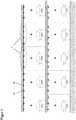
- the fire protection system comprises several fire protection units 1, each of which is assigned to a fire area B of the zone to be protected ( Figure 1 ).
- Each fire protection unit 1 comprises at least one sensor 11 for fire monitoring and at least one fire protection device 12 for fire fighting and / or for preventing the spread of fire.
- Each fire protection unit 1 can be controlled individually and independently of the other fire protection units 1.
- the fire protection units 1 are distributed over the zone to be protected, preferably in a kind of grid over the entire extent of a building. Fire monitoring and fire fighting is thus ensured three-dimensionally over the zone to be protected.
- the sensors 11 are suitable for measuring the temperature and / or the heat radiation and / or the infrared radiation and / or the detection of flames and / or smoke and / or gases, in particular combustion gases. It is particularly advantageous if the sensors 11 are suitable for the detection of those fire properties that indicate a battery fire (e.g. extreme heat radiation or temperature). In one possible embodiment variant of the invention, cameras can also be used as sensors 11. Certain electric vehicles are also equipped with fire detectors that emit a signal if there is a risk of a battery fire or if it already exists. In an advantageous embodiment variant of the invention, the fire protection system has receivers with which such a fire signal can be recorded so that the fire protection system can be put into operation early.
- water sprinklers foam sprinklers, water mist nozzles, deluge nozzles, ventilation openings, smoke protection curtains can be used as fire protection devices 12 and / or fire protection curtains are used.
- Vents can be connected to an exhaust system to remove smoke and / or combustion gases.
- a fire protection unit 1 comprises several different fire protection devices 12 in order to be able to appropriately treat different fire situations in the corresponding fire area B.
- a fire protection unit 1 could include both a water mist nozzle 12 and a water sprinkler 12.
- Water sprinklers are suitable for fighting conventional fires, for example for fighting a burning vehicle with an internal combustion engine. A burning electric vehicle cannot be extinguished using the classic methods, however, because burning batteries release enormous fire heat explosively and continue to burn for a very long time even without oxygen, unless they were "drowned" with an excessive amount of water.
- each different fire protection device 12 can be controlled individually and independently of the other fire protection devices 12, so that only the desired one can be triggered in the event of a fire.
- a fire protection unit 1 comprises several identical fire protection devices 12, which preferably form a fire protection group 13. This is advantageous if the fire area B, which is assigned to a fire protection unit 1, is larger than the range of the individual fire protection devices 12 and several identical fire protection devices 12 are distributed over the fire area B in order to cover it completely.
- each fire protection device 12 does not necessarily have to be controllable individually and independently of the other fire protection devices 12 of the same fire protection group 13, within a fire protection group 13 all fire protection devices 12 can be switched on and off simultaneously. It is important, however, that in a fire protection unit 1 with several different fire protection groups 13, each fire protection group 13 can be controlled individually and independently of the other fire protection groups 13. If a fire protection unit 1 comprises several different fire protection groups 13, it is advantageous if the fire protection groups 13 overlap so that each fire protection group 13 completely covers the fire area B assigned to the fire protection unit 1.
- the fire protection system is controlled in such a way that the optimal fire protection or fire-fighting measures are taken in each fire area B of the zone to be protected in order to counter the dynamics of the fire development and to make efficient use of the available water resources.
- the fire protection system is triggered and controlled on the basis of information about the conditions in the different fire areas, which are continuously recorded by the sensors 11 of the corresponding fire protection units 1 before and during the fire. Depending on the fire development, individual fire protection units 1 can therefore be switched on or off.
- the sensors 11 can provide information about the type of fire. It is particularly advantageous if, based on the information from the sensors 11, a fire in an electric vehicle can be distinguished from a fire in a conventional vehicle.
- each fire protection unit 1 is based on information from its own sensors 12 about the local ones Controlled conditions in the corresponding fire area B.
- water sprinklers 12 of a fire protection unit 1 can be triggered in order to spray water W on the source of the fire if the sensors 11 of the fire protection unit 1 detect a fire in the corresponding fire area B ( Figure 2 ). Since the fire protection devices 12 are only triggered in the fire area B, in which a fire is detected, the available water resources can be used efficiently and the entire performance of the fire protection system can be focused on this fire area B in order to achieve a maximum effect there.
- each fire protection unit 1 is additionally controlled on the basis of external information or information from sensors of other fire protection units 1.
- a fire protection unit 1 can transmit fire information to other fire protection units 1 removed from the fire as soon as this fire protection unit 1 detects a fire with its own sensor 11.
- Fire protection strategies can thus be developed that are not limited to simply fighting the fire in those fire areas B in which it has already gained a foothold, but also the spread of fire in others Prevent fire areas B.
- preventive measures can be taken in fire areas B, which are adjacent to the burning fire area B but in which there is still no fire.
- preventive measures primarily serve to prevent the spread of fire and can therefore deviate from the fire-fighting measures used to extinguish the source of the fire in burning area B.
- a possible preventive measure is, for example, that water mist N is generated in surrounding fire areas B, which absorbs the heat of the fire and thus causes strong cooling ( Figure 3 ). The cooling avoids that in further fire areas B of the zone to be protected that are distant from the fire, new fires are caused by the radiation energy and the fire spreads as a chain fire. In the meantime, the source of the fire could be combated directly with foam S or water W of the foam or water sprinkler 12.
- the fire protection strategy can consist primarily of preventive measures to protect non-burning fire areas B that are around the burning fire areas B, since a battery fire can only be extinguished with difficulty and the burning electric vehicle can usually no longer be saved anyway ,
- the performance of the fire protection system could primarily be based on this surrounding fire areas B are focused in order to achieve a maximum protective effect there, while in the area around the burning electric vehicle, for example, simply water mist N is generated ( Figure 4 ).
- an electric vehicle could burn out without the surrounding vehicles also catching fire.
- different preventive measures can be used by different fire protection units 1. So that the appropriate preventive measures can be used by the correct fire protection units 1, the fire information with which a fire is reported by a fire protection unit 1 preferably contains, among other things, the position and type of the fire.
- the fire protection system comprises a pipeline network 14 which is connected to the water supply to the building and / or to a water reservoir and with which certain fire protection devices 12, in particular the water sprinklers, foam sprinklers, water mist nozzles and / or Deluge nozzles in Fire protection groups 13 are connected ( Figure 5 ).
- Each of these fire protection groups 13 is individually and with a controllable area valve 15, which switches all fire protection devices 12 of the fire protection group on and off simultaneously controllable independently of the other fire protection groups 13.
- FIG 5 only one fire protection group 13 was shown in each fire area B.
- a fire protection unit 1 can comprise several different fire protection groups 13 which overlap, so that each fire protection group 13 completely covers the fire area B assigned to the fire protection unit 1. It is particularly advantageous if the fire protection system can be supported with additional feeds, for example to combat a major fire. These feeds can be put into operation by the fire brigade and come from internal or external sources. For example, it is advantageous if the fire brigade can feed normal and / or special extinguishing agents into the pipeline network 14. These extinguishing agents can, for example, be foam-forming or be intended for fire loads that are difficult to control, such as in the case of metal fires or lithium battery fires.
- the fire department carries out additional feeds of water or foam admixtures via a feed line which is connected to the pipeline network 14. It is important that the feeds can take place in a protected area away from the fire or outside the building.
- the fire protection system is provided with communication means with which a fire alarm, e.g. can be transmitted to the fire brigade or to a control body.
- the zone to be protected can be a two-dimensional building area, e.g. an entire floor or part of a floor, as well as a three-dimensional area, e.g. several floors of a building in which the fire areas B can not only be located horizontally next to each other but also vertically one above the other
- a burning electric vehicle not only releases considerable fire heat, but also a myriad of harmful chemicals, which come primarily from the batteries.
- Another problem that a burning electric vehicle poses is also the contamination of the extinguishing water with pollutants, in particular with heavy metals or alkali metals, from which electric batteries are composed.
- This extinguishing water must be subjected to special treatment and must not be discharged via the conventional drainage network or even released into the environment.
- a special design variant of the fire protection system also has a drainage system which is suitable for capturing and collecting contaminated extinguishing water.
- the drainage system comprises at least one collection unit 2, within which fire water can be collected and discharged to a suitable container.
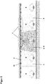
- the collecting unit 2 consists of an inclined floor area 21 of the zone to be protected, which is delimited by a floor elevation 22, so that the extinguishing water remains trapped in this floor area 21 at the deepest end of the floor area 21. So the floor areas 21 in the embodiment of the Figure 6a for example, be inclined perpendicular to the plane shown in the third dimension.
- a collecting unit 2 consists of two or more bottom regions 21, 21 '(inclined in a funnel-like manner) ( Figure 6b ).
- the entire zone to be protected can be divided into collection units 2 arranged next to one another, or only one or more collection units 2 can be provided in certain areas of the zone to be protected. It would be possible, for example, to provide certain parking spaces for electric vehicles on each floor of a parking garage, which are equipped with a collecting unit 2.
- a collection unit 2 can be a fire zone B zone to be protected and a fire protection unit of the fire protection system, but can also represent a larger or smaller floor area of the zone to be protected.
- the division according to the invention of the zone to be protected into independent fire areas with independently controllable fire protection units allows only those fire protection groups in which fire protection or fire fighting measures are necessary to be triggered and the desired measures to be used in every local fire area, in particular in the event of a fire in an electric vehicle. This avoids consequential damage from the extinguishing water and enables considerable water savings, so that the fire protection system can function even with limited water supply and allows efficient use of the available water resources.
- the fire protection system presented here is also particularly well suited for smaller parking lots that do not need an extinguishing system due to fire protection legislation. The fire protection system can easily be retrofitted in these parking lots on a voluntary basis without a complicated procedure.
- the fire brigade has the option of feeding additional water for the fire protection devices into the fire protection system and / or Controlling fire fighting by hand control from a safe area away from the fire with the help of sensors, whereby video surveillance in the fire area is an advantage if necessary.
- the optional additional drainage system allows contaminated fire water to be collected, especially when an electric vehicle is on fire, and prevents it from being released into the environment.
Landscapes
- Health & Medical Sciences (AREA)
- Public Health (AREA)
- Business, Economics & Management (AREA)
- Emergency Management (AREA)
- Fire-Extinguishing By Fire Departments, And Fire-Extinguishing Equipment And Control Thereof (AREA)
- Fire Alarms (AREA)
Abstract
Description
- Die vorliegende Erfindung betrifft ein Brandschutzsystem zur Brandbekämpfung und Verhinderung der Brandausbreitung gemäss Patentanspruch 1 und ein entsprechendes Verfahren gemäss Patentanspruch 7.
- Im heutigen Stand der Technik werden Auto-Einstellhallen oder Parkings mit technischen Brandschutz-Massnahmen geschützt, wobei meistens Sprinkleranlagen zum Einsatz kommen. Sprinkleranlagen bestehen aus einem geschlossenen Rohrleitungsnetz, welches in der Regel an oder in der Raumdecke montiert ist. In einer Art Rasterung sind die einzelnen Sprinkler geometrisch über die Deckenfläche verteilt in diesem Rohrleistungsnetz montiert und meist mittels auf Brandwärme reagierenden Thermoelementen verschlossen. Im Brandfall werden diese Thermoelemente durch die aufsteigende Brandwärme erhitzt und geben, wenn die Auslösebedingungen thermisch erreicht sind, den Löschwasseraustritt punktuell, dort wo die grösste Hitze entsteht, frei. Dieses bekannte System verfolgt das Ziel, den Wasseraustritt nur punktuell, Wasser-sparend, auf den Brandherd zu verteilen. Sprinkler haben also das Ziel, die Fläche unterhalb der ausgelösten Sprinkler zu schützen und die Brandausbreitung zu verhindern, indem idealerweise der Brand gelöscht wird.
- Neuerdings sind immer mehr elektrische Fahrzeuge mit High-Tech-Batterien betrieben. Diese Batterien haben den Nachteil, dass sie, wenn sie in Brand geraten, unter Umständen enorme Brandhitze explosionsartig freisetzen und ein solcher Batteriebrand mit herkömmlichen Mitteln kaum gelöscht werden kann (s. z.B.
WO2018222046A1 ). Diese Brandhitze stellt eine bisher in Parkhäusern nicht bekannte Hitzestrahlung dar. Sekundärbrände sind die Folge, das heisst, dass wenn die Batterie eines Elektrofahrzeugs in Brand gerät, nicht nur das in Brand geratene Auto brennt, sondern sehr schnell auch alles darum herum, was im Strahlungsumfeld dieses Autos steht. Derartige Brände sind für die Feuerwehrkräfte sehr gefährlich und es ist praktisch unmöglich, in der Enge eines Parkhauses die unkontrollierte Hitze- und Brandausbreitung mit klassischen Methoden zu bekämpfen, weil diese Batterien auch ohne Sauerstoff weiter brennen, ausser sie würden mit extrem viel Wasser "ersäuft" (s.WO2018222046A1 ). Diese benötigte Wassermenge und auch die technische Einrichtung zum "ersäufen" der Batterie steht allerdings nur an an wenigsten Orten zur Verfügung. - Die vorliegende Erfindung stellt sich nunmehr die Aufgabe, ein Brandschutzsystem und ein Verfahren zur Brandbekämpfung und Verhinderung der Brandausbreitung bereitzustellen, welches sich der Brandentwicklung dynamisch anpassen kann, zur Verhinderung der Ausbreitung von Bränden von Elektrofahrzeugen optimiert ist, einen effizienten Gebrauch der verfügbaren Wasserressourcen ermöglicht und auch mit beschränkter Wasserversorgung maximalen Schutz bietet.
- Diese Aufgabe lösen das Brandschutzsystem gemäss Patentanspruch 1 und ein entsprechendes Verfahren gemäss Patentanspruch 7. Weitere Merkmale und Ausführungsbeispiele gehen aus den abhängigen Ansprüchen hervor und deren Vorteile sind in der nachfolgenden Beschreibung erläutert.
- In den Zeichnungen zeigt:
- Figur 1
- Brandschutzsystem mit Brandschutzanlage
- Figur 2
- Ausführungsvariante des Brandschutzsystems mit Brandschutzanlage, in Betrieb
- Figur 3
- Ausführungsvariante des Brandschutzsystems mit Brandschutzanlage, in Betrieb
- Figur 4
- Ausführungsvariante des Brandschutzsystems mit Brandschutzanlage, in Betrieb
- Figur 5
- Ausführungsvariante des Brandschutzsystems mit Brandschutzanlage, Rohrleistungsnetz und Bereichsventil
- Figuren 6a-b
- Ausführungsvarianten der Entwässerungsanlage
- Die Figuren stellen mögliche Ausführungsbeispiele dar, welche in der nachfolgenden Beschreibung erläutert werden.
- Grundlage der Erfindung ist die Aufteilung einer zu schützenden Zone in unabhängige Brandbereiche B, in welchen unterschiedliche Brandschutz- bzw. Brandbekämpfungsmassnahmen getroffen werden können, um der Dynamik der Brandentwicklung in jedem Brandbereich B mit lokal geeigneten Massnahmen begegnen zu können.
- Das erfindungsgemässe Brandschutzsystem besteht aus einer Brandschutzanlage und optional aus einer zusätzlichen Entwässerungsanlage, die nachfolgend beschrieben werden.
- Die Brandschutzanlage umfasst mehrere Brandschutzeinheiten 1, die jeweils einem Brandbereich B der zu schützenden Zone zugeordnet sind (
Figur 1 ). Jede Brandschutzeinheit 1 umfasst zumindest einen Sensor 11 zur Brandüberwachung und zumindest eine Brandschutzeinrichtung 12 zur Brandbekämpfung und/oder zur Verhinderung der Brandausbreitung. Jede Brandschutzeinheit 1 ist individuell und unabhängig von den anderen Brandschutzeinheiten 1 steuerbar. Die Brandschutzeinheiten 1 sind über die zu schützende Zone verteilt, vorzugsweise in einer Art Rasterung über die gesamte Ausdehnung eines Gebäudes. Die Brandüberwachung und -bekämpfung wird dadurch dreidimensional über die zu schützende Zone sichergestellt. - Die Sensoren 11 sind zur Messung der Temperatur und/oder der Hitzestrahlung und/oder der Infrarotstrahlung und/oder der Detektion von Flammen und/oder Rauch und/oder Gasen, insbesondere Brandgasen, geeignet. Besonders vorteilhaft ist es insbesondere, wenn die Sensoren 11 für die Detektion von jenen Brandeigenschaften geeignet sind, die auf einen Batterie-Brand hinweisen (z.B. eine extreme Hitzestrahlung oder Temperatur). In einer möglichen Ausführungsvariante der Erfindung können als Sensoren 11 auch Kameras eingesetzt werden. Gewisse Elektrofahrzeuge sind ausserdem mit Brandmeldern versehen, die ein Signal ausgeben, wenn die Gefahr eines Batteriebrands droht oder dieser bereits vorliegt. In einer vorteilhaften Ausführungsvariante der Erfindung weist die Brandschutzanlage Empfänger auf, mit welchen ein derartiges Brandsignal aufgenommen werden kann, damit die Brandschutzanlage frühzeitig in Betrieb gesetzt werden kann.
- Als Brandschutzeinrichtungen 12 können beispielsweise Wassersprinkler, Schaumsprinkler, Wassernebel-Düsen, Deluge-Düsen, Entlüftungsöffnungen, Rauchschutzvorhänge und/oder Feuerschutzbehänge zum Einsatz kommen. Entlüftungsöffnungen können mit einer Absauganlage verbunden werden, um Rauch und/oder Brandgase abzuführen.
- Besonders vorteilhaft ist es, wenn eine Brandschutzeinheit 1 mehrere unterschiedliche Brandschutzeinrichtungen 12 umfasst, um im entsprechenden Brandbereich B unterschiedliche Brandsituationen angemessen behandeln zu können. So könnte beispielsweise eine Brandschutzeinheit 1 sowohl eine Wassernebel-Düse 12 als auch einen Wassersprinkler 12 umfassen. Wassersprinkler sind zur Bekämpfung von herkömmlichen Bränden geeignet, z.B. zur Bekämpfung eines brennenden Fahrzeugs mit Verbrennungsmotor. Ein brennendes Elektrofahrzeug kann aber mit den klassischen Methoden nicht gelöscht werden, weil brennende Batterieren enorme Brandhitze explosionsartig freisetzen und diese auch ohne Sauerstoff sehr lange weiter brennen, ausser sie würden mit extrem viel Wasser "ersäuft". Zur Bekämpfung eines Brandes eines Elektrofahrzeugs ist es daher von Vorteil, nicht den Brand des Fahrzeugs zu löschen, sondern in seinem Umfeld durch geeignete Wassernebel-Düsen ein Wassernebel zu erzeugen, welcher die Hitze des Brandes aufnimmt und eine starke Kühlung bewirkt, damit keine Sekundärbrände entstehen. Wichtig ist bei einer Brandschutzeinheit 1 mit mehreren unterschiedlichen Brandschutzeinrichtungen 12, dass jede unterschiedliche Brandschutzeinrichtung 12 individuell und unabhängig von den anderen Brandschutzeinrichtungen 12 steuerbar ist, damit im Brandfall nur die gewünschte ausgelöst werden kann.
- In möglichen Ausführungsvarianten der Erfindung umfasst eine Brandschutzeinheit 1 mehrere identische Brandschutzeinrichtungen 12, die vorzugsweise eine Brandschutzgruppe 13 bilden. Dies ist von Vorteil, wenn der Brandbereich B, der einer Brandschutzeinheit 1 zugeordnet ist, grösser als die Reichweite der einzelnen Brandschutzeinrichtungen 12 ist und mehrere identische Brandschutzeinrichtungen 12 über den Brandbereich B verteilt sind, um diesen vollständig abzudecken. In diesem Fall muss jede Brandschutzeinrichtung 12 nicht unbedingt individuell und unabhängig von den anderen Brandschutzeinrichtungen 12 der gleichen Brandschutzgruppe 13 steuerbar sein, innerhalb einer Brandschutzgruppe 13 können sämtliche Brandschutzeinrichtungen 12 gleichzeitig ein- und ausgeschaltet werden. Wichtig ist allerdings, dass bei einer Brandschutzeinheit 1 mit mehreren unterschiedlichen Brandschutzgruppen 13 jede Brandschutzgruppe 13 individuell und unabhängig von den anderen Brandschutzgruppen 13 steuerbar ist. Falls eine Brandschutzeinheit 1 mehrere unterschiedliche Brandschutzgruppen 13 umfasst, ist es von Vorteil, wenn sich die Brandschutzgruppen 13 überlappen, so dass jede Brandschutzgruppe 13 den der Brandschutzeinheit 1 zugeordneten Brandbereich B vollständig abdeckt.
- Im Brandfall wird die Brandschutzanlage derart gesteuert, dass in jedem Brandbereich B der zu schützenden Zone die optimalen Brandschutz- bzw. Brandbekämpfungsmassnahmen getroffen werden, um der Dynamik der Brandentwicklung zu begegnen und einen effizienten Gebrauch der verfügbaren Wasserressourcen zu machen. Dafür erfolgt die Auslösung und Steuerung der Brandschutzanlage aufgrund von Informationen über die Verhältnisse in den verschiedenen Brandbereichen, die durch die Sensoren 11 der entsprechenden Brandschutzeinheiten 1 vor und während des Brands laufend erfasst werden. Je nach Brandentwicklung können somit einzelne Brandschutzeinheiten 1 dazu geschaltet oder abgestellt werden. Zur optimalen Steuerung der Brandschutzanlage ist es von Vorteil, wenn die Sensoren 11 Informationen über die Art des Brandes liefern können. Besonders vorteilhaft ist es insbesondere, wenn aufgrund der Informationen aus den Sensoren 11 ein Brand eines Elektrofahrzeugs von einem Brand eines herkömmlichen Fahrzeugs unterschieden werden kann.
- In einer einfachen Ausführungsvariante der Brandschutzanlage wird jede Brandschutzeinheit 1 aufgrund von Informationen der eigenen Sensoren 12 über die lokalen Verhältnisse im entsprechenden Brandbereich B gesteuert. Zum Beispiel können Wassersprinkler 12 einer Brandschutzeinheit 1 ausgelöst werden, um Wasser W auf dem Brandherd zu besprühen, falls die Sensoren 11 der Brandschutzeinheit 1 im entsprechenden Brandbereich B einen Brand detektieren (
Figur 2 ). Da die Brandschutzeinrichtungen 12 nur im Brandbereich B ausgelöst werden, in welchen ein Brand detektiert wird, kann ein effizienter Gebrauch der verfügbaren Wasserressourcen gemacht werden und die gesamte Leistung der Brandschutzanlage auf diesen Brandbereich B fokussiert werden, um dort eine maximale Wirkung zu erreichen. - In einer weiteren Ausführungsvariante der Brandschutzanlage wird jede Brandschutzeinheit 1 zusätzlich aufgrund von externen Informationen oder Informationen aus Sensoren anderer Brandschutzeinheiten 1 gesteuert. Zum Beispiel kann eine Brandschutzeinheit 1 eine Brandinformation an andere, vom Brand entfernte Brandschutzeinheiten 1 übermitteln, sobald diese Brandschutzeinheit 1 mit einem eigenen Sensor 11 ein Brand detektiert. Es können somit Brandschutzstrategien entwickelt werden, die sich nicht nur auf die einfache Bekämpfung des Brandes in jenen Brandbereichen B beschränken, in welchen er schon Fuss fassen konnte, sondern auch die Brandausbreitung in weiteren Brandbereichen B verhindern. Beispielsweise können in den Brandbereichen B, die dem brennenden Brandbereich B benachbart sind aber in welchen noch kein Brand vorliegt, Präventionsmassnahmen getroffen werden. Diese Präventionsmassnahmen dienen vor allem der Verhinderung der Brandausbreitung und können somit von den Brandbekämpfungsmassnahmen abweichen, die zur Löschung des Brandherds im brennenden Brandbereich B eingesetzt werden. Eine mögliche Präventionsmassnahme besteht beispielsweise darin, dass in umliegenden Brandbereichen B Wassernebel N erzeugt wird, welcher die Hitze des Brandes aufnimmt und somit eine starke Kühlung bewirkt (
Figur 3 ). Die Kühlung vermeidet, dass in weiteren, vom Brand entfernten Brandbereichen B der zu schützenden Zone über die Strahlungsenergie neue Brände entstehen und der Brand sich als Kettenbrand ausbreitet. Währenddessen könnte der Brandherd beispielsweise mit Schaum S oder Wasser W der Schaum- bzw. Wassersprinkler 12 direkt bekämpft werden. Bei einem Brand eines Elektrofahrzeugs kann die Brandschutzstrategie vor allem aus Präventionsmassnahmen bestehen, zum Schutz von nicht-brennenden Brandbereichen B, die um die brennenden Brandbereiche B liegen, da ein Batteriebrand nur schwer gelöscht werden kann und das brennende Elektrofahrzeug meist sowieso nicht mehr gerettet werden kann. So könnte beispielsweise die Leistung der Brandschutzanlage vor allem auf diese umliegenden Brandbereiche B fokussiert werden, um dort eine maximale Schutzwirkung zu erreichen, während im Umfeld des brennenden Elektrofahrzeugs z.B. einfach Wassernebel N erzeugt wird (Figur 4 ). Im Sinne der Erfindung könnte somit ein Elektrofahrzeug ausbrennen, ohne dass die umliegenden Fahrzeuge auch in Brand geraten. Je nach Situation können also verschiedene Präventionsmassnahmen durch verschiedene Brandschutzeinheiten 1 eingesetzt werden. Damit die geeigneten Präventionsmassnahmen durch die richtigen Brandschutzeinheiten 1 eingesetzt werden können, enthält vorzugsweise die Brandinformation, mit welcher ein Brand von einer Brandschutzeinheit 1 gemeldet wird, u.a. die Position und Art des Brandes. - In einer möglichen Ausführungsvariante der Erfindung umfasst die Brandschutzanlage ein Rohrleitungsnetz 14, welches an die Wasserversorgung des Gebäudes und/oder an ein Wasserreservoir angeschlossen ist und mit welchem gewisse Brandschutzeinrichtungen 12, insbesondere die Wassersprinkler, Schaumsprinkler, Wassernebel-Düsen und/oder Deluge-Düsen in Brandschutzgruppen 13 verbunden sind (
Figur 5 ). Jede dieser Brandschutzgruppen 13 ist mit einem steuerbaren Bereichsventil 15, welches alle Brandschutzeinrichtungen 12 der Brandschutzgruppe gleichzeitig ein- und ausschaltet, individuell und unabhängig von den anderen Brandschutzgruppen 13 steuerbar. In derFigur 5 wurde in jedem Brandbereich B jeweils nur eine Brandschutzgruppe 13 dargestellt. In gewissen Ausführungsvarianten der Erfindung kann eine Brandschutzeinheit 1 mehrere unterschiedliche Brandschutzgruppen 13 umfassen, die sich überlappen, so dass jede Brandschutzgruppe 13 den der Brandschutzeinheit 1 zugeordneten Brandbereich B vollständig abdeckt. Besonders vorteilhaft ist es, wenn die Brandschutzanlage mit zusätzlichen Einspeisungen unterstützt werden kann, z.B. zur Bekämpfung eines Grossbrands. Diese Einspeisungen können von der Feuerwehr in Betrieb genommen werden und aus internen oder externen Quellen stammen. Von Vorteil ist es zum Beispiel, wenn die Feuerwehr in das Rohrleitungsnetz 14 normale und/oder spezielle Löschmittel einspeisen kann. Diese Löschmittel können zum Beispiel schaumbildend sein oder für schwer beherrschbare Brandlasten gedacht sein, wie zum Beispiel bei Metallbränden oder Lithium-Batteriebränden. In einer möglichen Ausführungsvariante der Erfindung erfolgen zusätzliche Einspeisungen von Wasser oder Schaum-Zumischungen durch die Feuerwehr über eine Einspeiseleitung, die mit dem Rohrleitungsnetz 14 verbunden ist. Wichtig ist dabei, dass die Einspeisungen in einem geschützten, vom Brand entfernten Bereich oder ausserhalb des Gebäudes erfolgen können. - In einer möglichen Ausführungsvariante ist die Brandschutzanlage mit Kommunikationsmitteln versehen, mit welchen eine Brandmeldung z.B. an die Feuerwehr oder an eine Kontrollstelle übermittelt werden kann.
- Die zu schützende Zone kann sowohl eine zweidimensionale Gebäudefläche sein, z.B. ein gesamtes Stockwerk oder einen Teil eines Stockwerks, wie auch ein dreidimensionaler Bereich, z.B. mehrere Stockwerke eines Gebäudes, in welchem die Brandbereiche B sich nicht nur horizontal nebeneinander sondern auch vertikal übereinander befinden können.
- Ein brennendes Elektrofahrzeug setzt nicht nur eine erhebliche Brandhitze frei, sondern auch eine Unzahl von schädlichen Chemikalien, die vor allem von den Batterien stammen. Ein weiteres Problem, das ein brennendes Elektrofahrzeug aufwirft, ist also auch die Verunreinigung des Löschwassers mit Schadstoffen, insbesondere mit Schwermetallen oder Alkalimetallen, aus welchen sich Elektrobatterien zusammensetzen. Dieses Löschwasser muss einer besonderen Aufbereitung unterzogen werden und darf nicht über das herkömmliche Entwässerungsnetz abgeführt oder sogar in die Umwelt abgegeben werden. Um dies zu vermeiden, weist eine besondere Ausführungsvariante des Brandschutzsystems zusätzlich eine Entwässerungsanlage auf, welche zum Einfangen und zur Sammlung von verunreinigtem Löschwasser geeignet ist.
- Die Entwässerungsanlage umfasst mindestens eine Sammeleinheit 2, innerhalb welcher Löschwasser gesammelt und zu einem geeigneten Behälter abgeführt werden kann. In einer möglichen Ausführungsvariante der Entwässerungsanlage besteht die Sammeleinheit 2 aus einem geneigten Bodenbereich 21 der zu schützenden Zone, der mit einer Bodenerhöhung 22 umgrenzt ist, so dass das Löschwasser in diesem Bodenbereich 21 eingefangen bleibt am tiefsten Ende des Bodenbereichs 21 gesammelt werden kann. So können die Bodenbereiche 21 in der Ausführungsvariante der
Figur 6a beispielsweise jeweils in der dritten Dimension senkrecht zur dargestellten Ebene geneigt sein. In weiteren möglichen Ausführungsvarianten besteht eine Sammeleinheit 2 aus zwei oder mehreren trichterartig geneigten Bodenbereichen 21, 21' (Figur 6b ). In einem Parkhaus kann die gesamte zu schützende Zone in nebeneinander angeordneten Sammeleinheiten 2 aufgeteilt sein, oder es können nur eine oder mehrere Sammeleinheiten 2 in gewissen Bereichen der zu schützenden Zone vorgesehen werden. Möglich wäre z.B. in jedem Stockwerk eines Parkhauses gewisse Parkplätze für Elektrofahrzeuge vorzusehen, die mit einer Sammeleinheit 2 ausgerüstet sind. Eine Sammeleinheit 2 kann einem Brandbereich B der zu schützenden Zone und einer Brandschutzeinheit des Brandschutzsystems entsprechen, aber kann auch eine grössere oder kleinere Bodenfläche der zu schützenden Zone darstellen. - Die erfindungsgemässe Aufteilung der zu schützenden Zone in unabhängige Brandbereiche mit unabhängig steuerbaren Brandschutzeinheiten erlaubt es, nur jene Brandschutzgruppen gezielt auszulösen, in welchen Brandschutz- bzw. Brandbekämpfungsmassnahmen erforderlich sind, und in jedem lokalen Brandbereich die gewünschten Massnahmen einzusetzen, insbesondere beim Brand eines Elektrofahrzeugs. Dies vermeidet Folgeschäden durch das Löschwasser und ermöglicht eine erhebliche Wassereinsparung, so dass das Brandschutzsystem auch mit beschränkter Wasserversorgung funktionsfähig ist und einen effizienten Gebrauch der verfügbaren Wasserressourcen erlaubt. Das vorgestellte Brandschutzsystem ist auch für kleinere Parkings besonders gut geeignet, die von der Brandschutzgesetzgebung her keine Löschanlage bräuchten. Das Brandschutzsystem kann auf freiwilliger Basis ohne kompliziertes Auflageverfahren in diesen Parkings einfach nachgerüstet werden. Um die bestehende Wasserversorgung zu ergänzen, besteht für die Feuerwehr die Möglichkeit, zusätzliches Wasser für die Brandschutzeinrichtungen in die Brandschutzanlage einzuspeisen und/oder die Brandbekämpfung via Handsteuerung aus einem sicheren, vom Brand entfernten Bereich mithilfe der Sensoren zu steuern, wobei allenfalls eine Videoüberwachung im Brandbereich von Vorteil ist. Die optionale zusätzliche Entwässerungsanlage erlaubt die Sammlung von verunreinigtem Löschwasser, insbesondere beim Brand eines Elektrofahrzeugs, und vermeidet, dass dieses in die Umwelt gelingt.
Claims (15)
- Brandschutzsystem umfassend eine Brandschutzanlage mit mehreren Brandschutzeinheiten (1), wobei
jede Brandschutzeinheit (1) mindestens einen Sensor (11) und mindestens eine Brandschutzeinrichtung (12) umfasst,
jede Brandschutzeinheit (1) aufgrund von Informationen aus einem eigenen Sensor (11) steuerbar ist, und
jede Brandschutzeinheit (1) individuell und unabhängig von den anderen Brandschutzeinheiten (1) steuerbar ist,
dadurch gekennzeichnet, dass
jede Brandschutzeinheit (1) zusätzlich aufgrund von Informationen aus Sensoren (12) anderer Brandschutzeinheiten (1) steuerbar ist. - Brandschutzsystem gemäss Anspruch 1,
dadurch gekennzeichnet, dass
ein Sensor (11) zur Messung der Temperatur und/oder der Hitzestrahlung und/oder der Infrarotstrahlung und/oder zur Detektion von Flammen und/oder von Rauch und/oder von Gasen geeignet ist. - Brandschutzsystem gemäss einem oder mehreren der vorhergehenden Ansprüche,
dadurch gekennzeichnet, dass
ein Sensor (11) für die Detektion von jenen Brandeigenschaften geeignet ist, die auf einen Batterie-Brand hinweisen. - Brandschutzsystem gemäss einem oder mehreren der vorhergehenden Ansprüche,
dadurch gekennzeichnet, dass
eine Brandschutzeinrichtung (12) ein Wassersprinkler und/oder ein Schaumsprinkler und/oder eine Wassernebel-Düse und/oder eine Deluge-Düse und/oder eine Entlüftungsöffnung und/oder ein Rauchschutzvorhang und/oder ein Feuerschutzbehang ist. - Brandschutzsystem gemäss einem oder mehreren der vorhergehenden Ansprüche,
dadurch gekennzeichnet, dass
eine Brandschutzeinheit (1) mehrere identische und/oder unterschiedliche Brandschutzeinrichtungen (12) umfasst. - Brandschutzsystem gemäss Anspruch 5,
dadurch gekennzeichnet, dass
mehrere identische Brandschutzeinrichtungen (12) zusammen eine Brandschutzgruppe 13 bilden. - Brandschutzsystem gemäss Ansprüchen 5 und 6,
dadurch gekennzeichnet, dass
eine Brandschutzeinheit (1) mehrere unterschiedliche Brandschutzgruppen (13) umfasst, die jeweils individuell und unabhängig von den anderen Brandschutzgruppen (13) steuerbar sind. - Brandschutzsystem gemäss Anspruch 7,
dadurch gekennzeichnet, dass
jede Brandschutzgruppe (13) mit einem steuerbaren Bereichsventil (15) steuerbar ist, welches alle Brandschutzeinrichtungen (12) der Brandschutzgruppe gleichzeitig ein- und ausschaltet. - Brandschutzsystem gemäss Anspruch 1,
gekennzeichnet durch
eine Entwässerungsanlage mit mindestens einer Sammeleinheit (2), innerhalb welcher Löschwasser sammelbar und zu einem Behälter abführbar ist. - Brandschutzverfahren mit dem Brandschutzsystem gemäss einem oder mehreren der Ansprüche 1 bis 9,
dadurch gekennzeichnet, dass
eine Brandschutzeinheit (1) mit einem eigenen Sensor (11) einen Brand detektiert, und
eine Brandinformation an andere, vom Brand entferne Brandschutzeinheiten (1) übermittelt wird. - Brandschutzverfahren gemäss Anspruch 10,
dadurch gekennzeichnet, dass
eine vom Brandherd entfernte Brandschutzeinheit (1) aufgrund einer Brandinformation einer anderen Brandschutzeinheit (1) eine Präventionsmassnahme zur Verhinderung der Brandausbreitung einsetzt. - Brandschutzverfahren gemäss Anspruch 11,
dadurch gekennzeichnet, dass
eine Präventionsmassnahme von einer Brandbekämpfungsmassnahme abweicht, die zur Löschung des Brandherds eingesetzt wird. - Brandschutzverfahren gemäss Anspruch 11,
dadurch gekennzeichnet, dass
eine Brandinformation die Position und Art des Brandes enthält, und
eine Brandschutzeinheit (1), die dem Brandherd benachbart ist, eine für die gemeldete Brandart geeignete Präventionsmassnahme einsetzt, indem die geeigneten Brandschutzeinrichtungen (12) ausgelöst werden. - Brandschutzverfahren gemäss Anspruch 13,
dadurch gekennzeichnet, dass
die Brandschutzeinheiten (1), die einem brennenden Elektroauto benachbart sind, einen Wassernebel erzeugen, wobei die Leistung der Brandschutzanlage auf diese Brandschutzeinheiten (1) fokussiert wird. - Brandschutzverfahren gemäss Anspruch 10,
dadurch gekennzeichnet, dass
Brandinformationen vor und während des Brands durch die Sensoren (11) laufend erfasst werden, damit je nach Brandentwicklung einzelne Brandschutzeinheiten (1) dynamisch dazu geschaltet oder ausgeschaltet werden.
Applications Claiming Priority (1)
| Application Number | Priority Date | Filing Date | Title |
|---|---|---|---|
| EP18190001.0A EP3613471A1 (de) | 2018-08-21 | 2018-08-21 | Brandschutzsystem sowie verfahren zur verhinderung der brandausbreitung in einer zu schützenden zone |
Publications (3)
| Publication Number | Publication Date |
|---|---|
| EP3613472A2 true EP3613472A2 (de) | 2020-02-26 |
| EP3613472A3 EP3613472A3 (de) | 2020-05-06 |
| EP3613472B1 EP3613472B1 (de) | 2022-08-10 |
Family
ID=63350435
Family Applications (2)
| Application Number | Title | Priority Date | Filing Date |
|---|---|---|---|
| EP18190001.0A Withdrawn EP3613471A1 (de) | 2018-08-21 | 2018-08-21 | Brandschutzsystem sowie verfahren zur verhinderung der brandausbreitung in einer zu schützenden zone |
| EP19192663.3A Active EP3613472B1 (de) | 2018-08-21 | 2019-08-20 | Brandschutzsystem und -verfahren |
Family Applications Before (1)
| Application Number | Title | Priority Date | Filing Date |
|---|---|---|---|
| EP18190001.0A Withdrawn EP3613471A1 (de) | 2018-08-21 | 2018-08-21 | Brandschutzsystem sowie verfahren zur verhinderung der brandausbreitung in einer zu schützenden zone |
Country Status (2)
| Country | Link |
|---|---|
| EP (2) | EP3613471A1 (de) |
| DK (1) | DK3613472T3 (de) |
Cited By (4)
| Publication number | Priority date | Publication date | Assignee | Title |
|---|---|---|---|---|
| CN112370702A (zh) * | 2020-11-16 | 2021-02-19 | 国网浙江电动汽车服务有限公司 | 一种火灾预告警装置及方法 |
| CN112494871A (zh) * | 2020-12-08 | 2021-03-16 | 山东高速工程检测有限公司 | 一种公路隧道智能消防系统 |
| EP4306178A1 (de) | 2022-07-14 | 2024-01-17 | Ackermann GmbH Aufbauten- und Fahrzeugvertrieb | Löschstation zur brandbekämpfung in einer fahrzeugbatterie und verfahren zum löschen eines brands bei einer fahrzeugbatterie |
| WO2026019366A1 (en) * | 2024-07-16 | 2026-01-22 | Nanyang Technological University | A high-efficiency smoke extraction method for large flat space with low headroom |
Families Citing this family (4)
| Publication number | Priority date | Publication date | Assignee | Title |
|---|---|---|---|---|
| DE102020103814A1 (de) | 2020-02-13 | 2021-08-19 | Minimax Viking Research & Development Gmbh | Brandlöschsystem für ein Dach mit einer Solaranlage |
| CN114093142B (zh) * | 2020-08-05 | 2023-09-01 | 安霸国际有限合伙企业 | 通过组合视觉传感和热传感的对象感知的温度异常监控和预警 |
| DE102021129589B4 (de) | 2021-11-12 | 2023-11-09 | Stadtwerke Bonn Verkehrs-GmbH (SWBV) | Brandschutzanlage und Verfahren zu ihrem Betrieb |
| EP4512486B1 (de) | 2023-08-24 | 2025-10-08 | Minimax Viking Patent Management GmbH | Brandschutzsysteme für dachsolarpaneelinstallationen, verfahren und wassersprühdüsen dafür |
Citations (1)
| Publication number | Priority date | Publication date | Assignee | Title |
|---|---|---|---|---|
| WO2018222046A1 (en) | 2017-05-30 | 2018-12-06 | Extinctus As | Device for fire extinguishing energy storage devices of vehicles with electrical drive |
Family Cites Families (6)
| Publication number | Priority date | Publication date | Assignee | Title |
|---|---|---|---|---|
| US5486811A (en) * | 1994-02-09 | 1996-01-23 | The United States Of America As Represented By The Secretary Of The Navy | Fire detection and extinguishment system |
| DE19949093A1 (de) * | 1999-10-12 | 2001-04-19 | Preussag Ag Minimax | Feuerlöschanlage |
| EP1103284A3 (de) * | 1999-11-24 | 2001-09-19 | Siemens Building Technologies AG | Brandbekämpfungssystem für Autotunnels |
| AT411571B (de) * | 2001-10-17 | 2004-03-25 | Hainzl Industriesysteme Gmbh & | Anlage zur brandbekämpfung in einem tunnel, insbesondere einem strassentunnel |
| GB201020539D0 (en) * | 2010-12-03 | 2011-01-19 | Pdx Technologies Ag | An improved apparatus for generating mist and foams |
| DK177678B1 (da) * | 2011-12-19 | 2014-02-24 | Vid Fire Kill Aps | Modulært fast installeret tunnel brand beskyttelses system. |
-
2018
- 2018-08-21 EP EP18190001.0A patent/EP3613471A1/de not_active Withdrawn
-
2019
- 2019-08-20 DK DK19192663.3T patent/DK3613472T3/da active
- 2019-08-20 EP EP19192663.3A patent/EP3613472B1/de active Active
Patent Citations (1)
| Publication number | Priority date | Publication date | Assignee | Title |
|---|---|---|---|---|
| WO2018222046A1 (en) | 2017-05-30 | 2018-12-06 | Extinctus As | Device for fire extinguishing energy storage devices of vehicles with electrical drive |
Cited By (4)
| Publication number | Priority date | Publication date | Assignee | Title |
|---|---|---|---|---|
| CN112370702A (zh) * | 2020-11-16 | 2021-02-19 | 国网浙江电动汽车服务有限公司 | 一种火灾预告警装置及方法 |
| CN112494871A (zh) * | 2020-12-08 | 2021-03-16 | 山东高速工程检测有限公司 | 一种公路隧道智能消防系统 |
| EP4306178A1 (de) | 2022-07-14 | 2024-01-17 | Ackermann GmbH Aufbauten- und Fahrzeugvertrieb | Löschstation zur brandbekämpfung in einer fahrzeugbatterie und verfahren zum löschen eines brands bei einer fahrzeugbatterie |
| WO2026019366A1 (en) * | 2024-07-16 | 2026-01-22 | Nanyang Technological University | A high-efficiency smoke extraction method for large flat space with low headroom |
Also Published As
| Publication number | Publication date |
|---|---|
| EP3613472A3 (de) | 2020-05-06 |
| EP3613471A1 (de) | 2020-02-26 |
| EP3613472B1 (de) | 2022-08-10 |
| DK3613472T3 (en) | 2022-11-07 |
Similar Documents
| Publication | Publication Date | Title |
|---|---|---|
| EP3613472B1 (de) | Brandschutzsystem und -verfahren | |
| DE102016212645B4 (de) | Unbemanntes Fahrzeug, System und Verfahren zur Einleitung einer Brandlöschaktion | |
| DE102018100579B4 (de) | Löschroboter | |
| EP3485472B1 (de) | System und verfahren zur verifizierten bestimmung eines brandzustands sowie fahrzeug und zentraleinheit dafür | |
| DE10012705B4 (de) | Verfahren und Vorrichtung zum Früherkennen und Bekämpfen von Feuer im Innen- und Außenbereich, insbesondere Wohnbereich, von Häusern und Gebäuden | |
| WO2019020639A1 (de) | Temperiervorrichtung für eine temperierung eines batteriesystems, batteriesystem sowie verfahren zum temperieren und/oder löschen eines batteriesystems | |
| WO2011103915A1 (de) | Verfahren und einrichtung zur thermischen überwachung mittels eines löschsystems zum löschen eines brandes | |
| DE602004013260T2 (de) | System zur Rauchgasabfuhr in Tunneln | |
| EP3829724A1 (de) | Verfahren zur bekämpfung eines brandereignisses und system zur durchführung des verfahrens | |
| EP4274008A1 (de) | Behältnis zur lagerung von batterien sowie dessen verwendung | |
| DE202021103253U1 (de) | Depot zur Aufbewahrung eines Fahrzeugs | |
| DE19945856A1 (de) | Sprinklervorrichtung mit einem Ventil für Löschflüssigkeit | |
| DE202024000438U1 (de) | Branderkennungs- und -bekämpfungssystem für einen Parkplatz eines Elektrofahrzeugs | |
| WO2012010987A1 (de) | Kombinierte heiz-, kühl- und feuerlöschanlage für gebäude | |
| DE102019122138B4 (de) | Verfahren und Vorrichtung zur Feuerbekämpfung in, an oder vor einem Objekt | |
| DE29911569U1 (de) | Automatisches Brandschutzsystem für Verkehrstunnels | |
| EP4429781B1 (de) | Brandschutzanlage und verfahren zu ihrem betrieb | |
| DE102022101363A1 (de) | Löschmodul zum Entgegenwirken eines Batteriebrands, Löscheinrichtung, Parkeinrichtung und Verfahren zum Entgegenwirken eines Batteriebrands | |
| DE102012102299A1 (de) | Brandschutzvlies, Brandschutzvorrichtung, Verwendung eines Brandschutzvlieses und Verfahren zur Herstellung eines Brandschutzvlieses | |
| DE102019113457B4 (de) | Brandschutzverfahren und -vorrichtung | |
| DE102015002817A1 (de) | Brandschutz durch Material mit geringem Feuerwiderstand, vorzugsweise an Abluftöffnung | |
| DE202006006068U1 (de) | Raumlöschsäule | |
| DE102024110190A1 (de) | Fahrerloses Transportfahrzeug | |
| DE60129290T2 (de) | Verfahren und Vorrichtung mit Wassernebel zum Feuerlöschen und/oder zum Einsatz gegen Gifte in Verkehrstunnels | |
| AT519421A1 (de) | Prüfraum zur aufnahme einer elektrochemischen vorrichtung |
Legal Events
| Date | Code | Title | Description |
|---|---|---|---|
| PUAI | Public reference made under article 153(3) epc to a published international application that has entered the european phase |
Free format text: ORIGINAL CODE: 0009012 |
|
| STAA | Information on the status of an ep patent application or granted ep patent |
Free format text: STATUS: REQUEST FOR EXAMINATION WAS MADE |
|
| 17P | Request for examination filed |
Effective date: 20190920 |
|
| AK | Designated contracting states |
Kind code of ref document: A2 Designated state(s): AL AT BE BG CH CY CZ DE DK EE ES FI FR GB GR HR HU IE IS IT LI LT LU LV MC MK MT NL NO PL PT RO RS SE SI SK SM TR |
|
| AX | Request for extension of the european patent |
Extension state: BA ME |
|
| PUAL | Search report despatched |
Free format text: ORIGINAL CODE: 0009013 |
|
| AK | Designated contracting states |
Kind code of ref document: A3 Designated state(s): AL AT BE BG CH CY CZ DE DK EE ES FI FR GB GR HR HU IE IS IT LI LT LU LV MC MK MT NL NO PL PT RO RS SE SI SK SM TR |
|
| AX | Request for extension of the european patent |
Extension state: BA ME |
|
| RIC1 | Information provided on ipc code assigned before grant |
Ipc: A62C 99/00 20100101ALI20200401BHEP Ipc: A62C 35/58 20060101AFI20200401BHEP Ipc: A62C 37/40 20060101ALI20200401BHEP |
|
| STAA | Information on the status of an ep patent application or granted ep patent |
Free format text: STATUS: EXAMINATION IS IN PROGRESS |
|
| 17Q | First examination report despatched |
Effective date: 20210311 |
|
| GRAP | Despatch of communication of intention to grant a patent |
Free format text: ORIGINAL CODE: EPIDOSNIGR1 |
|
| STAA | Information on the status of an ep patent application or granted ep patent |
Free format text: STATUS: GRANT OF PATENT IS INTENDED |
|
| INTG | Intention to grant announced |
Effective date: 20220321 |
|
| GRAS | Grant fee paid |
Free format text: ORIGINAL CODE: EPIDOSNIGR3 |
|
| GRAA | (expected) grant |
Free format text: ORIGINAL CODE: 0009210 |
|
| STAA | Information on the status of an ep patent application or granted ep patent |
Free format text: STATUS: THE PATENT HAS BEEN GRANTED |
|
| AK | Designated contracting states |
Kind code of ref document: B1 Designated state(s): AL AT BE BG CH CY CZ DE DK EE ES FI FR GB GR HR HU IE IS IT LI LT LU LV MC MK MT NL NO PL PT RO RS SE SI SK SM TR |
|
| REG | Reference to a national code |
Ref country code: AT Ref legal event code: REF Ref document number: 1510055 Country of ref document: AT Kind code of ref document: T Effective date: 20220815 Ref country code: CH Ref legal event code: EP |
|
| REG | Reference to a national code |
Ref country code: DE Ref legal event code: R096 Ref document number: 502019005217 Country of ref document: DE |
|
| REG | Reference to a national code |
Ref country code: IE Ref legal event code: FG4D Free format text: LANGUAGE OF EP DOCUMENT: GERMAN |
|
| REG | Reference to a national code |
Ref country code: DK Ref legal event code: T3 Effective date: 20221101 Ref country code: NO Ref legal event code: T2 Effective date: 20220810 |
|
| REG | Reference to a national code |
Ref country code: SE Ref legal event code: TRGR |
|
| REG | Reference to a national code |
Ref country code: NL Ref legal event code: MP Effective date: 20220810 |
|
| REG | Reference to a national code |
Ref country code: LT Ref legal event code: MG9D |
|
| PG25 | Lapsed in a contracting state [announced via postgrant information from national office to epo] |
Ref country code: RS Free format text: LAPSE BECAUSE OF FAILURE TO SUBMIT A TRANSLATION OF THE DESCRIPTION OR TO PAY THE FEE WITHIN THE PRESCRIBED TIME-LIMIT Effective date: 20220810 Ref country code: PT Free format text: LAPSE BECAUSE OF FAILURE TO SUBMIT A TRANSLATION OF THE DESCRIPTION OR TO PAY THE FEE WITHIN THE PRESCRIBED TIME-LIMIT Effective date: 20221212 Ref country code: NL Free format text: LAPSE BECAUSE OF FAILURE TO SUBMIT A TRANSLATION OF THE DESCRIPTION OR TO PAY THE FEE WITHIN THE PRESCRIBED TIME-LIMIT Effective date: 20220810 Ref country code: LV Free format text: LAPSE BECAUSE OF FAILURE TO SUBMIT A TRANSLATION OF THE DESCRIPTION OR TO PAY THE FEE WITHIN THE PRESCRIBED TIME-LIMIT Effective date: 20220810 Ref country code: LT Free format text: LAPSE BECAUSE OF FAILURE TO SUBMIT A TRANSLATION OF THE DESCRIPTION OR TO PAY THE FEE WITHIN THE PRESCRIBED TIME-LIMIT Effective date: 20220810 Ref country code: FI Free format text: LAPSE BECAUSE OF FAILURE TO SUBMIT A TRANSLATION OF THE DESCRIPTION OR TO PAY THE FEE WITHIN THE PRESCRIBED TIME-LIMIT Effective date: 20220810 |
|
| PG25 | Lapsed in a contracting state [announced via postgrant information from national office to epo] |
Ref country code: PL Free format text: LAPSE BECAUSE OF FAILURE TO SUBMIT A TRANSLATION OF THE DESCRIPTION OR TO PAY THE FEE WITHIN THE PRESCRIBED TIME-LIMIT Effective date: 20220810 Ref country code: IS Free format text: LAPSE BECAUSE OF FAILURE TO SUBMIT A TRANSLATION OF THE DESCRIPTION OR TO PAY THE FEE WITHIN THE PRESCRIBED TIME-LIMIT Effective date: 20221210 Ref country code: HR Free format text: LAPSE BECAUSE OF FAILURE TO SUBMIT A TRANSLATION OF THE DESCRIPTION OR TO PAY THE FEE WITHIN THE PRESCRIBED TIME-LIMIT Effective date: 20220810 Ref country code: GR Free format text: LAPSE BECAUSE OF FAILURE TO SUBMIT A TRANSLATION OF THE DESCRIPTION OR TO PAY THE FEE WITHIN THE PRESCRIBED TIME-LIMIT Effective date: 20221111 |
|
| PG25 | Lapsed in a contracting state [announced via postgrant information from national office to epo] |
Ref country code: SM Free format text: LAPSE BECAUSE OF FAILURE TO SUBMIT A TRANSLATION OF THE DESCRIPTION OR TO PAY THE FEE WITHIN THE PRESCRIBED TIME-LIMIT Effective date: 20220810 Ref country code: RO Free format text: LAPSE BECAUSE OF FAILURE TO SUBMIT A TRANSLATION OF THE DESCRIPTION OR TO PAY THE FEE WITHIN THE PRESCRIBED TIME-LIMIT Effective date: 20220810 Ref country code: LU Free format text: LAPSE BECAUSE OF NON-PAYMENT OF DUE FEES Effective date: 20220820 Ref country code: ES Free format text: LAPSE BECAUSE OF FAILURE TO SUBMIT A TRANSLATION OF THE DESCRIPTION OR TO PAY THE FEE WITHIN THE PRESCRIBED TIME-LIMIT Effective date: 20220810 Ref country code: CZ Free format text: LAPSE BECAUSE OF FAILURE TO SUBMIT A TRANSLATION OF THE DESCRIPTION OR TO PAY THE FEE WITHIN THE PRESCRIBED TIME-LIMIT Effective date: 20220810 |
|
| REG | Reference to a national code |
Ref country code: BE Ref legal event code: MM Effective date: 20220831 |
|
| REG | Reference to a national code |
Ref country code: DE Ref legal event code: R097 Ref document number: 502019005217 Country of ref document: DE |
|
| PG25 | Lapsed in a contracting state [announced via postgrant information from national office to epo] |
Ref country code: SK Free format text: LAPSE BECAUSE OF FAILURE TO SUBMIT A TRANSLATION OF THE DESCRIPTION OR TO PAY THE FEE WITHIN THE PRESCRIBED TIME-LIMIT Effective date: 20220810 Ref country code: MC Free format text: LAPSE BECAUSE OF FAILURE TO SUBMIT A TRANSLATION OF THE DESCRIPTION OR TO PAY THE FEE WITHIN THE PRESCRIBED TIME-LIMIT Effective date: 20220810 Ref country code: EE Free format text: LAPSE BECAUSE OF FAILURE TO SUBMIT A TRANSLATION OF THE DESCRIPTION OR TO PAY THE FEE WITHIN THE PRESCRIBED TIME-LIMIT Effective date: 20220810 |
|
| PLBE | No opposition filed within time limit |
Free format text: ORIGINAL CODE: 0009261 |
|
| STAA | Information on the status of an ep patent application or granted ep patent |
Free format text: STATUS: NO OPPOSITION FILED WITHIN TIME LIMIT |
|
| PG25 | Lapsed in a contracting state [announced via postgrant information from national office to epo] |
Ref country code: AL Free format text: LAPSE BECAUSE OF FAILURE TO SUBMIT A TRANSLATION OF THE DESCRIPTION OR TO PAY THE FEE WITHIN THE PRESCRIBED TIME-LIMIT Effective date: 20220810 |
|
| 26N | No opposition filed |
Effective date: 20230511 |
|
| PG25 | Lapsed in a contracting state [announced via postgrant information from national office to epo] |
Ref country code: IE Free format text: LAPSE BECAUSE OF NON-PAYMENT OF DUE FEES Effective date: 20220820 |
|
| PG25 | Lapsed in a contracting state [announced via postgrant information from national office to epo] |
Ref country code: SI Free format text: LAPSE BECAUSE OF FAILURE TO SUBMIT A TRANSLATION OF THE DESCRIPTION OR TO PAY THE FEE WITHIN THE PRESCRIBED TIME-LIMIT Effective date: 20220810 |
|
| PG25 | Lapsed in a contracting state [announced via postgrant information from national office to epo] |
Ref country code: BE Free format text: LAPSE BECAUSE OF NON-PAYMENT OF DUE FEES Effective date: 20220831 |
|
| PG25 | Lapsed in a contracting state [announced via postgrant information from national office to epo] |
Ref country code: HU Free format text: LAPSE BECAUSE OF FAILURE TO SUBMIT A TRANSLATION OF THE DESCRIPTION OR TO PAY THE FEE WITHIN THE PRESCRIBED TIME-LIMIT; INVALID AB INITIO Effective date: 20190820 |
|
| PG25 | Lapsed in a contracting state [announced via postgrant information from national office to epo] |
Ref country code: CY Free format text: LAPSE BECAUSE OF FAILURE TO SUBMIT A TRANSLATION OF THE DESCRIPTION OR TO PAY THE FEE WITHIN THE PRESCRIBED TIME-LIMIT Effective date: 20220810 |
|
| PG25 | Lapsed in a contracting state [announced via postgrant information from national office to epo] |
Ref country code: MK Free format text: LAPSE BECAUSE OF FAILURE TO SUBMIT A TRANSLATION OF THE DESCRIPTION OR TO PAY THE FEE WITHIN THE PRESCRIBED TIME-LIMIT Effective date: 20220810 Ref country code: IT Free format text: LAPSE BECAUSE OF FAILURE TO SUBMIT A TRANSLATION OF THE DESCRIPTION OR TO PAY THE FEE WITHIN THE PRESCRIBED TIME-LIMIT Effective date: 20220810 |
|
| PG25 | Lapsed in a contracting state [announced via postgrant information from national office to epo] |
Ref country code: BG Free format text: LAPSE BECAUSE OF FAILURE TO SUBMIT A TRANSLATION OF THE DESCRIPTION OR TO PAY THE FEE WITHIN THE PRESCRIBED TIME-LIMIT Effective date: 20220810 |
|
| PG25 | Lapsed in a contracting state [announced via postgrant information from national office to epo] |
Ref country code: MT Free format text: LAPSE BECAUSE OF FAILURE TO SUBMIT A TRANSLATION OF THE DESCRIPTION OR TO PAY THE FEE WITHIN THE PRESCRIBED TIME-LIMIT Effective date: 20220810 |
|
| PGFP | Annual fee paid to national office [announced via postgrant information from national office to epo] |
Ref country code: DE Payment date: 20250811 Year of fee payment: 7 Ref country code: DK Payment date: 20250811 Year of fee payment: 7 |
|
| PGFP | Annual fee paid to national office [announced via postgrant information from national office to epo] |
Ref country code: NO Payment date: 20250805 Year of fee payment: 7 |
|
| REG | Reference to a national code |
Ref country code: AT Ref legal event code: MM01 Ref document number: 1510055 Country of ref document: AT Kind code of ref document: T Effective date: 20240820 |
|
| PGFP | Annual fee paid to national office [announced via postgrant information from national office to epo] |
Ref country code: GB Payment date: 20250804 Year of fee payment: 7 |
|
| PG25 | Lapsed in a contracting state [announced via postgrant information from national office to epo] |
Ref country code: AT Free format text: LAPSE BECAUSE OF NON-PAYMENT OF DUE FEES Effective date: 20240820 |
|
| PGFP | Annual fee paid to national office [announced via postgrant information from national office to epo] |
Ref country code: FR Payment date: 20250804 Year of fee payment: 7 |
|
| PGFP | Annual fee paid to national office [announced via postgrant information from national office to epo] |
Ref country code: SE Payment date: 20250804 Year of fee payment: 7 |
|
| REG | Reference to a national code |
Ref country code: CH Ref legal event code: U11 Free format text: ST27 STATUS EVENT CODE: U-0-0-U10-U11 (AS PROVIDED BY THE NATIONAL OFFICE) Effective date: 20251104 |
|
| PG25 | Lapsed in a contracting state [announced via postgrant information from national office to epo] |
Ref country code: TR Free format text: LAPSE BECAUSE OF FAILURE TO SUBMIT A TRANSLATION OF THE DESCRIPTION OR TO PAY THE FEE WITHIN THE PRESCRIBED TIME-LIMIT Effective date: 20220810 |
|
| PGFP | Annual fee paid to national office [announced via postgrant information from national office to epo] |
Ref country code: CH Payment date: 20251104 Year of fee payment: 7 |
|
| PGFP | Annual fee paid to national office [announced via postgrant information from national office to epo] |
Ref country code: AT Payment date: 20260410 Year of fee payment: 5 |