EP3613935A1 - Dichtungsmuffe und ausziehbare leiter - Google Patents
Dichtungsmuffe und ausziehbare leiter Download PDFInfo
- Publication number
- EP3613935A1 EP3613935A1 EP17906070.2A EP17906070A EP3613935A1 EP 3613935 A1 EP3613935 A1 EP 3613935A1 EP 17906070 A EP17906070 A EP 17906070A EP 3613935 A1 EP3613935 A1 EP 3613935A1
- Authority
- EP
- European Patent Office
- Prior art keywords
- closure plate
- rails
- upper closure
- segmental
- plate
- Prior art date
- Legal status (The legal status is an assumption and is not a legal conclusion. Google has not performed a legal analysis and makes no representation as to the accuracy of the status listed.)
- Granted
Links
Images


Classifications
-
- E—FIXED CONSTRUCTIONS
- E06—DOORS, WINDOWS, SHUTTERS, OR ROLLER BLINDS IN GENERAL; LADDERS
- E06C—LADDERS
- E06C1/00—Ladders in general
- E06C1/02—Ladders in general with rigid longitudinal member or members
- E06C1/04—Ladders for resting against objects, e.g. walls poles, trees
- E06C1/08—Ladders for resting against objects, e.g. walls poles, trees multi-part
- E06C1/12—Ladders for resting against objects, e.g. walls poles, trees multi-part extensible, e.g. telescopic
- E06C1/125—Ladders for resting against objects, e.g. walls poles, trees multi-part extensible, e.g. telescopic with tubular longitudinal members nested within each other
-
- E—FIXED CONSTRUCTIONS
- E06—DOORS, WINDOWS, SHUTTERS, OR ROLLER BLINDS IN GENERAL; LADDERS
- E06C—LADDERS
- E06C7/00—Component parts, supporting parts, or accessories
-
- E—FIXED CONSTRUCTIONS
- E06—DOORS, WINDOWS, SHUTTERS, OR ROLLER BLINDS IN GENERAL; LADDERS
- E06C—LADDERS
- E06C1/00—Ladders in general
- E06C1/02—Ladders in general with rigid longitudinal member or members
- E06C1/38—Special constructions of ladders, e.g. ladders with more or less than two longitudinal members, ladders with movable rungs or other treads, longitudinally-foldable ladders
- E06C1/383—Foldable ladders in which the longitudinal members are brought together on folding
-
- E—FIXED CONSTRUCTIONS
- E06—DOORS, WINDOWS, SHUTTERS, OR ROLLER BLINDS IN GENERAL; LADDERS
- E06C—LADDERS
- E06C7/00—Component parts, supporting parts, or accessories
- E06C7/08—Special construction of longitudinal members, or rungs or other treads
-
- E—FIXED CONSTRUCTIONS
- E06—DOORS, WINDOWS, SHUTTERS, OR ROLLER BLINDS IN GENERAL; LADDERS
- E06C—LADDERS
- E06C1/00—Ladders in general
- E06C1/02—Ladders in general with rigid longitudinal member or members
- E06C1/14—Ladders capable of standing by themselves
- E06C1/16—Ladders capable of standing by themselves with hinged struts which rest on the ground
- E06C1/18—Ladders capable of standing by themselves with hinged struts which rest on the ground with supporting struts formed as ladders
-
- E—FIXED CONSTRUCTIONS
- E06—DOORS, WINDOWS, SHUTTERS, OR ROLLER BLINDS IN GENERAL; LADDERS
- E06C—LADDERS
- E06C1/00—Ladders in general
- E06C1/02—Ladders in general with rigid longitudinal member or members
- E06C1/14—Ladders capable of standing by themselves
- E06C1/16—Ladders capable of standing by themselves with hinged struts which rest on the ground
- E06C1/20—Ladders capable of standing by themselves with hinged struts which rest on the ground with supporting struts formed as poles
- E06C1/22—Ladders capable of standing by themselves with hinged struts which rest on the ground with supporting struts formed as poles with extensible, e.g. telescopic, ladder parts or struts
-
- E—FIXED CONSTRUCTIONS
- E06—DOORS, WINDOWS, SHUTTERS, OR ROLLER BLINDS IN GENERAL; LADDERS
- E06C—LADDERS
- E06C7/00—Component parts, supporting parts, or accessories
- E06C7/003—Indicating devices, e.g. user warnings or inclinators
Definitions
- the present disclosure relates to the technical field of daily tools, and in particular to a closure cover and an extension ladder.
- An extension ladder is a ladder allowing a person to work at a high place that can be stretched and extended when in use, and can be folded, shortened for storing when not in use.
- the commonly used extension ladder comprises ladder rails, consisting of a plurality of segmental rails (rail segments), and transverse ladder steps (rungs), the plurality of segmental rails are gradually reduced in size, the adjacent segmental rails are extendably sleeved and fixed to each other, and each of the segmental rails is fixed with a transverse ladder step.
- the segmental rails When not in use, the segmental rails are all retracted into an inner cavity of the segmental rail with the largest size, and the transverse ladder steps are brought into contact with each other, and at this time, the extension ladder has the minimum overall size and can be stored conveniently.
- the extension ladder When in use, the extension ladder is stretched so that a distance between each two adjacent transverse ladder steps is increased to a set position, and then the positional relation between the adjacent segmental rails is fixed by a locking device so that the relative positions of the adjacent transverse ladder steps remain unchanged.
- An object of the present disclosure is to provide a closure cover and an extension ladder to alleviate the technical problem that the extension ladder in the prior art is likely to cause a pinching injury or a crush injury to the user due to an excessively fast descending speed during retraction.
- the present disclosure provides a closure cover comprising an upper closure plate, a lower closure plate, and two airtight sheets (air-closing pieces), wherein the upper closure plate and the lower closure plate are fixedly connected by a connector, the upper closure plate and the lower closure plate are each provided thereon with ventilation holes, one of the two airtight sheets is fixed to a surface of the upper closure plate facing away from the lower closure plate, with the other one airtight sheet fixed to a surface of the lower closure plate facing away from the upper closure plate, and each of the airtight sheets is capable of controlling respectively closing and opening of the ventilation holes,.
- each of the airtight sheets is a circular elastic sheet
- a connecting hole is provided at the center of each of the airtight sheets
- a screw hole is provided at the center of each of the upper closure plate and the lower closure plate, and each of the screws sequentially passes through the respective pressure plate and the connecting hole and is screwed tight and fixed into the screw hole.
- each of the airtight sheets is a circular elastic sheet
- a connecting hole is provided at the center of each of the airtight sheets
- a stud is disposed at a center of the surface of the upper closure plate away from the lower closure plate and at a center of the surface of the lower closure plate away from the upper closure plate respectively, and each of the studs sequentially passes through the connecting hole and the respective pressure plate and is screwed tight and fixed with the screw nut.
- each of the upper closure plate and the lower closure plate is provided with an air outlet hole for slow-descending, wherein each of the air outlet holes for slow-descending is remote from the airtight sheets.
- sealing rings are further included, a side edge of each of the upper closure plate and the lower closure plate is provided with a sealing ring groove, and the sealing rings are fixed in the sealing ring grooves, respectively.
- the connector is a cylindrical supporting column having two ends fixed at central positions of the upper closure plate and the lower closure plate, respectively; and the supporting column, the upper closure plate, and the lower closure plate are formed integrally.
- the present disclosure further provides an extension ladder comprising two ladder rails and a plurality of transverse ladder steps; wherein each of the ladder rails comprises a plurality of segmental rails and a plurality of closure covers described above; and the segmental rails on the two ladder rails are in one-to-one correspondence, and two ends of each of the transverse ladder steps are respectively fixed to one ends of the two corresponding segmental rails which are in one-to-one correspondence, with the one ends fixed to the upper closure plates.
- an air-bleed hole is provided at an intermediate position of each of the segmental rails.
- At least one elastic fastener is disposed on a surface of each of the lower closure plate facing the upper closure plates respectively, at least one snapping groove is disposed at a corresponding position of an inner wall of each of the segmental rails, and the elastic fasteners can be snap-fitted in the snapping grooves.
- fixing pins are further included, wherein the connectors and the segmental rails are provided with pin holes, and each of the upper closure plates is fixedly connected with each of the segmental rails by passing the fixing pins through the two pin holes, respectively.
- the closure cover and the extension ladder according to the present disclosure have the following advantageous effects:
- the closure cover according to the present disclosure comprises an upper closure plate, a lower closure plate, and two airtight sheets.
- Each of the airtight sheets have an area capable of ensuring sealing and blocking the ventilation holes on the upper closure plate and the lower closure plate when the airtight sheets are attached and fixed to the upper closure plate and the lower closure plate.
- the connector allows the upper closure plate and the lower closure plate to be positioned fixedly relative to each other while forming a cavity therebetween.
- a slow descending function of the extension ladder is accomplished by fixing this closure cover between two adjacent segmental rails.
- the upper closure plate is sleeved and fixed to one end of one segmental rail
- the lower closure plate is sleeved in a cavity of the other segmental rail
- a sealing member is disposed both between a side edge of the upper closure plate and an inner wall of the segmental rail and between a side edge of the lower closure plate and an inner wall of the other segmental rail
- the segmental rail to which the upper closure plate is fixed is extendably sleeved in the inner cavity of the segmental rail in which the lower closure plate is sleeved.
- the cavity between the upper closure plate and the lower closure plate communicates with the outside through a gap between the adjacent segmental rails, and is at standard atmospheric pressure.
- the cavity between the upper closure plate of one closure cover and the lower closure plate of another adjacent closure cover is at an underpressure, and the cavity between the upper closure plate and the lower closure plate gives the airtight sheets a force away from the upper closure plate or the lower closure plate, so that the airtight sheets are deformed, and the ventilation holes are exposed, and thus the pressure in the cavity between the upper closure plate of one closure cover and the lower closure plate of another adjacent closure cover is quickly restored to standard atmospheric pressure, thereby ensuring easy and effortless stretching between the segmental rails.
- extension ladder according to the present disclosure are the same as those of the closure cover described above, and therefore are not described repeatedly herein.
- Reference Numerals 100-upper closure plate; 200-lower closure plate; 300-airtight sheet; 400-pressure plate; 500-screw; 600-segmental rail; 700-sealing ring; 800-connector; 101-ventilation hole; 102-air outlet hole for slow-descending; 103-sealing ring groove; 201-elastic fastener; 601-air-bleed hole; 602-snapping groove.
- orientation or positional relations indicated by the terms such as “center”, “up”, “down”, “left”, “right”, “vertical”, “horizontal”, “inside”, and “outside” are the orientation or positional relations shown based on the drawings, and these terms are intended only to facilitate the description of the present disclosure and simplify the description, but not intended to indicate or imply that the referred devices or elements must be in a particular orientation or constructed or operated in the particular orientation, and therefore should not be construed as limiting the present disclosure.
- the terms “first”, “second”, and “third” are used for descriptive purpose only, and should not be understood as an indication or implication of relative importance.
- connection may be a fixed connection or a detachable connection or an integral connection, may be a mechanical connection or an electric connection, or may be a direct coupling or an indirect coupling via an intermediate medium or internal communication between two elements.
- connection may be a fixed connection or a detachable connection or an integral connection, may be a mechanical connection or an electric connection, or may be a direct coupling or an indirect coupling via an intermediate medium or internal communication between two elements.
- FIG. 1 is a structural schematic view of a closure cover according to an embodiment of the present disclosure
- FIG. 2 is an exploded structural schematic view of a closure cover according to an embodiment of the present disclosure
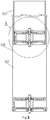
- FIG. 3 is a half-sectional view of an extension ladder according to an embodiment of the present disclosure
- FIG. 4 is a structural schematic view of A in FIG. 3 .
- an embodiment of the present disclosure provides a closure cover comprising an upper closure plate 100, a lower closure plate 200, and two airtight sheets 300, wherein the upper closure plate 100 and the lower closure plate 200 are fixedly connected by a connector 800, the upper closure plate 100 and the lower closure plate 200 are each provided thereon with ventilation holes 101, one of the two airtight sheets 300 is fixed to a surface of the upper closure plate 100 facing away from the lower closure plate 200, with the other airtight sheet fixed to a surface of the lower closure plate 200 facing away from the upper closure plate 100, and each of the airtight sheets 300 is capable of controlling respectively the closing and opening of the ventilation holes 101.
- the closure cover according to the embodiment of the present disclosure comprises an upper closure plate 100, a lower closure plate 200, and two airtight sheets 300.
- Each of the airtight sheets 300 has an area capable of ensuring sealing and blocking the ventilation holes 101 on the upper closure plate 100 and the lower closure plate 200 when the airtight sheets are attached and fixed to the upper closure plate 100 and the lower closure plate 200.
- the connector 800 allows the upper closure plate 100 and the lower closure plate 200 to be positioned fixedly relative to each other while forming a cavity therebetween.
- the slow descending function of an extension ladder is accomplished by fixing this closure cover between two adjacent segmental rails 600.
- the upper closure plate 100 is sleeved and fixed to one end of one segmental rail 600
- the lower closure plate 200 is sleeved in a cavity of the other segmental rail 600
- a sealing member is disposed both between a side edge of the upper closure plate 100 and an inner wall of the segmental rail 600 and between a side edge of the lower closure plate 200 and an inner wall of the other segmental rail 600
- the segmental rail 600 to which the upper closure plate 100 is fixed is extendably sleeved in the inner cavity of the segmental rail 600 in which the lower closure plate 200 is sleeved.
- the cavity between the upper closure plate 100 and the lower closure plate 200 communicates with the outside through a gap between the adjacent segmental rails 600, and is at standard atmospheric pressure.
- the segmental rails 600 are stretched relative to each other, the cavity between the upper closure plate 100 of one closure cover and the lower closure plate 200 of another adjacent closure cover is at an underpressure, and the cavity between the upper closure plate 100 and the lower closure plate 200 gives the airtight sheets 300 a force away from the upper closure plate 100 or the lower closure plate 200, so that the airtight sheets 300 are deformed, and the ventilation hole 101 are exposed, and thus the cavity between the upper closure plate 100 of one closure cover and the lower closure plate 200 of another adjacent closure cover is quickly restored to standard atmospheric pressure, thereby ensuring easy and effortless stretching between the segmental rails 600.
- a plurality of ventilation holes 101 are provided in the present embodiment, and are arranged on the upper closure plate 100 and the lower closure plate 200 in a ring shape around center points of the upper closure plate 100 and the lower closure plate 200.
- the airtight sheets 300 are provided as circular elastic sheets made of metal.
- each of the circular elastic sheets has a small thickness to ensure easy deformation under a force, and moreover, it has good elasticity so that it is disposed to be almost attached to (abutted against) the upper closure plate 100 and the lower closure plate 200 in a state where no force is applied, thereby ensuring the sealing effect by the airtight sheets 300 to the ventilation holes 101 and ensuring the easy and effortless stretching effect by its easy deformability during the stretching of the segmental rails 600.
- the central positions of the airtight sheets 300 and the central positions of the upper closure plate 100 and the lower closure plate 200 are fixed relative to each other to ensure that portions of the airtight sheets 300 at the positions of the respective ventilation holes 101 are in the same deformation state when forces of the same magnitude are applied thereto, so that the airtight sheets 300 have a stable deformation rule, and the service life of the airtight sheets 300 are increased.
- the fixing between the airtight sheets 300 and each of the upper closure plate 100 and the lower closure plate 200 are carried out in the following two manners.
- screws 500 (which may also be bolts) and pressure plates 400 may be disposed, a connecting hole is provided at the center of each of the airtight sheets 300, a screw 500 hole (which may be a threaded hole) is provided at the center of each of the upper closure plate 100 and the lower closure plate 200, and each of the screws 500 sequentially passes through the respective pressure plate 400 and the connecting hole and is screwed tight and fixed into the screw 500 hole.
- screw nuts and pressure plates 400 may be disposed, a connecting hole is provided at the center of each of the airtight sheets 300, a stud is disposed at a center of the surface of the upper closure plate 100 away from the lower closure plate and at a center of a surface of the lower closure plate 200 away from the upper closure plate, and each of the studs sequentially passes through the connecting hole and the respective pressure plate 400 and is screwed tight and fixed with the screw nut.
- each of the pressure plates 400 is configured to increase a contact area with the airtight sheets 300, so that the airtight sheets 300 are further attached and fixed to the upper closure plate 100 and the lower closure plate 200.
- each of the upper closure plate 100 and the lower closure plate 200 is further provided thereon with an air outlet hole for slow-descending 102, and each of the air outlet holes for slow-descending 102 is remote from the airtight sheets 300.
- Each of the air outlet holes for slow-descending 102 has a very small hole diameter, such that when the segmental rails 600 are retracted, the air in the cavity between the upper closure plate 100 of one closure cover and the lower closure plate 200 of another adjacent closure cover can be slowly discharged from the air outlet holes for slow-descending 102, and the retraction efficiency of the extension ladder is accelerated on the premise of ensuring that the speed at which the segmental rails 600 are slowly retracted does not cause a safety hazard to the user.
- sealing rings 700 are further included in the present embodiment, a side edge of each of the upper closure plate 100 and the lower closure plate 200 is provided with a sealing ring groove 103, and the sealing rings 700 are fixed in the sealing ring grooves 103.
- the connector 800 provided in the present embodiment is a cylindrical supporting column having two ends fixed at the central positions of the upper closure plate 100 and the lower closure plate 200, respectively, and the supporting column, the upper closure plate 100, and the lower closure plate 200 are provided to be formed integrally; and a cavity communicating with the outside is formed between the upper closure plate 100 and the lower closure plate 200 while ensuring a stable overall structure of the closure cover.
- the connector 800 may also be provided as a reinforcing rib disposed radially.
- the reinforcing rib has a larger contact area with the upper closure plate 100 and the lower closure plate 200, thereby further ensuring the stability of the closure cover as a whole.
- the present embodiment provides an extension ladder comprising two ladder rails and a plurality of transverse ladder steps; wherein each of the ladder rails comprises a plurality of segmental rails 600 and a plurality of the closure covers described above; the segmental rails 600 on the two ladder rails are in one-to-one correspondence, and two ends of each of the transverse ladder steps are respectively fixed to one ends of the two corresponding segmental rails 600 which are in one-to-one correspondence, with the one ends fixed to the upper closure plates 100.
- extension ladder does not cause a safety hazard such as a pinching injury or a crush injury to the user due to an excessively fast speed during retraction, and the extension ladder is also stretched easily and effortlessly during extension.
- the extension ladder may also consist of one ladder rail and a plurality of transverse ladder steps, as long as it is ensured that the connections between the transverse ladder steps and the ladder rail can stably bear the weight of the user.
- an air-bleed hole 601 is provided at an intermediate position of each of the segmental rails 600.
- Each of the air-bleed holes 601 allows the cavity between the upper closure plate 100 of one closure cover and the lower closure plate 200 of another adjacent closure cover to communicate with the outside. While the segmental rails 600 are being retracted and pressed downward, when the lower closure plate 200 of the upper one closure cover does not pass the air-bleed hole 601, the cavity does not exert a jacking force on the upper segmental rail 600, and the segmental rail 600 is accelerated downward; and when the lower closure plate 200 of the upper one closure cover passes the air-bleed hole 601, the air in the cavity cannot be discharged, and the internal pressure is increased, and thus a jacking force is exerted on the upper segmental rail 600, and the descending speed of the segmental rail 600 is slowed down, whereby the slow descending function of the extension ladder is accomplished.
- the provision of the air-bleed holes 601 further increases the retraction efficiency of the extension ladder to meet the needs of the user, while ensuring that the slow descending function of the extension ladder is unchanged.
- the air-bleed holes 601 may also be located at other positions of each of the segmental rails 600 by changing and adjusting the number and diameter of the air-bleed holes 601 while ensuring that the slow descending function of the extension ladder is unchanged.
- At least one elastic fastener 201 is disposed on a surface of each of the lower closure plates 200 facing the upper closure plates 100 respectively, at least one snapping groove 602 is disposed at a corresponding position of the inner wall of each of the segmental rails 600, and the elastic fasteners 201 can be snap-fitted in the snapping grooves 602.
- the upper closure plate 100 of each of the closure covers is controlled to slide toward the inner cavity of the each of the segmental rails 600 and at the same time drive the elastic fasteners 201 to enter the inner cavity until a protrusion at the top end of each of the elastic fasteners 201 is engaged in the snapping groove 602 in the inner wall of each of the segmental rails 600, whereby the fixing of the closure covers are accomplished.
- closure covers and the segmental rails 600 may also be fixed by insertion pins.
- fixing pins are further included in the present embodiment, the connectors 800 and the segmental rails 600 are provided with pin holes, and each of the upper closure plates 100 is fixedly connected with each of the segmental rails 600 by passing the fixing pins through the two pin holes, respectively.
- each of the lower closure plates 200 is inserted into a next segmental rail 600
- the insertion end of each of the segmental rails 600 may be provided with a stop ring for preventing the lower closure plate 200 of each of the closure covers from being removed from the segmental rails 600.
Landscapes
- Engineering & Computer Science (AREA)
- Mechanical Engineering (AREA)
- Ladders (AREA)
Applications Claiming Priority (2)
| Application Number | Priority Date | Filing Date | Title |
|---|---|---|---|
| CN201710260165.6A CN107191132B (zh) | 2017-04-20 | 2017-04-20 | 封口套及伸缩梯 |
| PCT/CN2017/091530 WO2018192095A1 (zh) | 2017-04-20 | 2017-07-03 | 封口套及伸缩梯 |
Publications (3)
| Publication Number | Publication Date |
|---|---|
| EP3613935A1 true EP3613935A1 (de) | 2020-02-26 |
| EP3613935A4 EP3613935A4 (de) | 2020-04-22 |
| EP3613935B1 EP3613935B1 (de) | 2021-01-20 |
Family
ID=59871882
Family Applications (1)
| Application Number | Title | Priority Date | Filing Date |
|---|---|---|---|
| EP17906070.2A Active EP3613935B1 (de) | 2017-04-20 | 2017-07-03 | Dichtungsmuffe und ausziehbare leiter |
Country Status (4)
| Country | Link |
|---|---|
| US (1) | US10934776B2 (de) |
| EP (1) | EP3613935B1 (de) |
| CN (1) | CN107191132B (de) |
| WO (1) | WO2018192095A1 (de) |
Families Citing this family (4)
| Publication number | Priority date | Publication date | Assignee | Title |
|---|---|---|---|---|
| CN209908391U (zh) * | 2019-04-04 | 2020-01-07 | 东莞凯丰家居用品有限公司 | 一种伸缩梯杆单元 |
| USD959024S1 (en) | 2020-12-04 | 2022-07-26 | Dorel Home Furnishings, Inc. | Tray for telescoping ladder |
| CN113338789A (zh) * | 2021-06-30 | 2021-09-03 | 佛山市顺德区万怡家居用品有限公司 | 伸缩梯的缓降结构 |
| CN116008389B (zh) * | 2023-02-07 | 2025-04-11 | 苏州华天国科电力科技有限公司 | 一种基于超声声纹的变压器油在线监测装置 |
Family Cites Families (34)
| Publication number | Priority date | Publication date | Assignee | Title |
|---|---|---|---|---|
| JP3471438B2 (ja) * | 1993-12-06 | 2003-12-02 | 株式会社ショーワ | 緩衝器のバルブ構造 |
| JP3542645B2 (ja) * | 1994-09-20 | 2004-07-14 | 隆 寺本 | 梯子 |
| GB2305956B (en) * | 1995-10-02 | 1999-10-06 | Gary Kuo | An extension ladder with telescopic legs |
| DE19615583C2 (de) * | 1996-04-19 | 1998-12-17 | Mannesmann Sachs Ag | Schwingungsdämpfer mit Vordrosselscheibe |
| DE19923927C1 (de) * | 1999-05-27 | 2001-01-18 | Mannesmann Sachs Ag | Umschaltventil mit strömungsrichtungsabhängigem Querschnitt |
| US6672436B1 (en) * | 2000-04-19 | 2004-01-06 | Tenneco Automotive Operating Company Inc. | Variable bleed orifice valving |
| DE10047433C1 (de) * | 2000-09-26 | 2002-01-03 | Stabilus Gmbh | Kolben-Zylinderaggregat mit Bremseinrichtung |
| CA2409812A1 (en) * | 2001-10-29 | 2003-04-29 | Bombardier Inc. | Shock absorber with adjustable valving |
| US6644445B2 (en) * | 2001-11-19 | 2003-11-11 | Tenneco Automotive Operating Company Inc. | Floating port blocker |
| US20060283664A1 (en) * | 2005-06-17 | 2006-12-21 | Kuo-Ching Yao | Extension ladder apparatus |
| US20060283665A1 (en) * | 2005-06-17 | 2006-12-21 | Kuo-Ching Yao | Extension ladder with improved structure |
| GB2436584B (en) * | 2006-03-30 | 2011-08-31 | Norman William Liefke | An extension ladder with improved mechanism |
| US7316293B2 (en) * | 2006-05-17 | 2008-01-08 | Norman William Liefke | Extension ladder with improved mechanism |
| DE102006029380B3 (de) * | 2006-06-27 | 2008-01-17 | Thyssenkrupp Bilstein Suspension Gmbh | Dämpfungselement |
| CN201170058Y (zh) * | 2008-01-21 | 2008-12-24 | 郭晶耀 | 伸缩梯 |
| CN201212352Y (zh) * | 2008-05-14 | 2009-03-25 | 郭晶耀 | 伸缩梯 |
| US8225906B2 (en) * | 2008-08-22 | 2012-07-24 | Core Distribution, Inc. | Extendable/retractable ladder |
| US8869939B2 (en) * | 2008-09-25 | 2014-10-28 | Ching Yao Kuo | Extension ladder |
| JP5192441B2 (ja) * | 2009-05-20 | 2013-05-08 | カヤバ工業株式会社 | 減衰バルブ |
| CN203334945U (zh) * | 2013-05-30 | 2013-12-11 | 东莞鼎翰铝制品有限公司 | 伸缩梯的节杆及伸缩梯 |
| JP5787961B2 (ja) * | 2013-10-31 | 2015-09-30 | 日立オートモティブシステムズ株式会社 | 緩衝器 |
| JP5783647B2 (ja) * | 2013-11-08 | 2015-09-24 | カヤバ工業株式会社 | バルブ |
| US9416591B2 (en) * | 2014-12-02 | 2016-08-16 | Core Distribution, Inc. | Telescoping ladder with stabilizers |
| CN204436248U (zh) * | 2015-02-10 | 2015-07-01 | 陈肖玲 | 一种带缓冲功能的伸缩梯子 |
| GB2536297B (en) * | 2015-03-13 | 2017-03-01 | Teletower Com Ltd | Damper for the stiles of a telescopic ladder |
| US10435946B2 (en) * | 2015-11-28 | 2019-10-08 | Otto Martinus Nielsen | Collapsible ladder |
| CN205400572U (zh) * | 2016-03-24 | 2016-07-27 | 傅迪 | 一种伸缩梯缓降装置 |
| CN205638198U (zh) * | 2016-05-17 | 2016-10-12 | 李勇豪 | 一种气阻缓降安全伸缩梯 |
| CN205840753U (zh) * | 2016-06-22 | 2016-12-28 | 永康市富士家居用品有限公司 | 一种安全伸缩梯 |
| CN205859033U (zh) * | 2016-07-04 | 2017-01-04 | 傅迪 | 一种气压缓降装置及安装有该装置的伸缩梯 |
| CN206111921U (zh) * | 2016-07-06 | 2017-04-19 | 董佐明 | 伸缩梯气缸 |
| EP3538733B1 (de) * | 2016-11-14 | 2022-01-05 | Lampe Holding B.V. | Teleskopleiter |
| CN206418954U (zh) * | 2017-01-10 | 2017-08-18 | 潘跃进 | 伸缩梯子的缓降机构 |
| CN206647039U (zh) * | 2017-04-20 | 2017-11-17 | 黄金钗 | 封口套及伸缩梯 |
-
2017
- 2017-04-20 CN CN201710260165.6A patent/CN107191132B/zh not_active Expired - Fee Related
- 2017-07-03 WO PCT/CN2017/091530 patent/WO2018192095A1/zh not_active Ceased
- 2017-07-03 US US16/303,676 patent/US10934776B2/en active Active
- 2017-07-03 EP EP17906070.2A patent/EP3613935B1/de active Active
Also Published As
| Publication number | Publication date |
|---|---|
| WO2018192095A1 (zh) | 2018-10-25 |
| CN107191132B (zh) | 2019-10-22 |
| EP3613935A4 (de) | 2020-04-22 |
| US20200173232A1 (en) | 2020-06-04 |
| EP3613935B1 (de) | 2021-01-20 |
| CN107191132A (zh) | 2017-09-22 |
| US10934776B2 (en) | 2021-03-02 |
Similar Documents
| Publication | Publication Date | Title |
|---|---|---|
| EP3613935B1 (de) | Dichtungsmuffe und ausziehbare leiter | |
| US11549670B2 (en) | Pin-type connection apparatus | |
| CN103379787A (zh) | 固定装置 | |
| WO2024131299A1 (zh) | 升降设备及升降系统 | |
| CN113431235A (zh) | 一种玻璃幕墙安装结构 | |
| CN205349214U (zh) | 一种伸缩梯 | |
| CN206647039U (zh) | 封口套及伸缩梯 | |
| CN216529208U (zh) | 一种电池盖防掉结构 | |
| CN220354234U (zh) | 快速拆装锁扣系统 | |
| CN218442127U (zh) | 一种嵌入式灯具的安装装置 | |
| CN211318525U (zh) | 一种弱电工程安全检测装置 | |
| CN210717270U (zh) | 落地式工矿灯 | |
| CN209062077U (zh) | 链条固定装置 | |
| CN207315825U (zh) | 一种便于在通孔正面拆装的螺栓组件 | |
| CN212676038U (zh) | 一种空调用小型直流变压器设备 | |
| CN100595855C (zh) | 一种接触器的安装装置 | |
| CN219472544U (zh) | 一种防拆安全紧固件组件 | |
| CN112983142B (zh) | 锁具以及具有该锁具的自动泄压开关柜 | |
| CN208707177U (zh) | 一种变电站伸缩式多功能地刀闸的操作杆 | |
| CN218344922U (zh) | 一种导轨组件以及平台电梯 | |
| CN223595116U (zh) | 一种粉尘无焰泄放装置 | |
| CN216196436U (zh) | 一种便携式移动登高检修作业平台 | |
| CN215174509U (zh) | 一种便于维修的灯具结构 | |
| CN209129517U (zh) | 胶管式防爆波活门 | |
| CN221810952U (zh) | 一种不脱出螺钉组件及钣金组件紧固结构 |
Legal Events
| Date | Code | Title | Description |
|---|---|---|---|
| STAA | Information on the status of an ep patent application or granted ep patent |
Free format text: STATUS: THE INTERNATIONAL PUBLICATION HAS BEEN MADE |
|
| PUAI | Public reference made under article 153(3) epc to a published international application that has entered the european phase |
Free format text: ORIGINAL CODE: 0009012 |
|
| STAA | Information on the status of an ep patent application or granted ep patent |
Free format text: STATUS: REQUEST FOR EXAMINATION WAS MADE |
|
| 17P | Request for examination filed |
Effective date: 20181031 |
|
| AK | Designated contracting states |
Kind code of ref document: A1 Designated state(s): AL AT BE BG CH CY CZ DE DK EE ES FI FR GB GR HR HU IE IS IT LI LT LU LV MC MK MT NL NO PL PT RO RS SE SI SK SM TR |
|
| AX | Request for extension of the european patent |
Extension state: BA ME |
|
| REG | Reference to a national code |
Ref country code: DE Ref legal event code: R079 Ref document number: 602017031907 Country of ref document: DE Free format text: PREVIOUS MAIN CLASS: E06C0007000000 Ipc: E06C0001120000 |
|
| A4 | Supplementary search report drawn up and despatched |
Effective date: 20200320 |
|
| RIC1 | Information provided on ipc code assigned before grant |
Ipc: E06C 1/12 20060101AFI20200316BHEP |
|
| DAV | Request for validation of the european patent (deleted) | ||
| DAX | Request for extension of the european patent (deleted) | ||
| GRAP | Despatch of communication of intention to grant a patent |
Free format text: ORIGINAL CODE: EPIDOSNIGR1 |
|
| STAA | Information on the status of an ep patent application or granted ep patent |
Free format text: STATUS: GRANT OF PATENT IS INTENDED |
|
| INTG | Intention to grant announced |
Effective date: 20200811 |
|
| GRAS | Grant fee paid |
Free format text: ORIGINAL CODE: EPIDOSNIGR3 |
|
| GRAA | (expected) grant |
Free format text: ORIGINAL CODE: 0009210 |
|
| STAA | Information on the status of an ep patent application or granted ep patent |
Free format text: STATUS: THE PATENT HAS BEEN GRANTED |
|
| AK | Designated contracting states |
Kind code of ref document: B1 Designated state(s): AL AT BE BG CH CY CZ DE DK EE ES FI FR GB GR HR HU IE IS IT LI LT LU LV MC MK MT NL NO PL PT RO RS SE SI SK SM TR |
|
| REG | Reference to a national code |
Ref country code: GB Ref legal event code: FG4D |
|
| REG | Reference to a national code |
Ref country code: CH Ref legal event code: EP |
|
| REG | Reference to a national code |
Ref country code: AT Ref legal event code: REF Ref document number: 1356546 Country of ref document: AT Kind code of ref document: T Effective date: 20210215 |
|
| REG | Reference to a national code |
Ref country code: IE Ref legal event code: FG4D |
|
| REG | Reference to a national code |
Ref country code: DE Ref legal event code: R096 Ref document number: 602017031907 Country of ref document: DE |
|
| REG | Reference to a national code |
Ref country code: NL Ref legal event code: FP |
|
| REG | Reference to a national code |
Ref country code: LT Ref legal event code: MG9D |
|
| REG | Reference to a national code |
Ref country code: AT Ref legal event code: MK05 Ref document number: 1356546 Country of ref document: AT Kind code of ref document: T Effective date: 20210120 |
|
| PG25 | Lapsed in a contracting state [announced via postgrant information from national office to epo] |
Ref country code: LT Free format text: LAPSE BECAUSE OF FAILURE TO SUBMIT A TRANSLATION OF THE DESCRIPTION OR TO PAY THE FEE WITHIN THE PRESCRIBED TIME-LIMIT Effective date: 20210120 Ref country code: BG Free format text: LAPSE BECAUSE OF FAILURE TO SUBMIT A TRANSLATION OF THE DESCRIPTION OR TO PAY THE FEE WITHIN THE PRESCRIBED TIME-LIMIT Effective date: 20210420 Ref country code: PT Free format text: LAPSE BECAUSE OF FAILURE TO SUBMIT A TRANSLATION OF THE DESCRIPTION OR TO PAY THE FEE WITHIN THE PRESCRIBED TIME-LIMIT Effective date: 20210520 Ref country code: NO Free format text: LAPSE BECAUSE OF FAILURE TO SUBMIT A TRANSLATION OF THE DESCRIPTION OR TO PAY THE FEE WITHIN THE PRESCRIBED TIME-LIMIT Effective date: 20210420 Ref country code: GR Free format text: LAPSE BECAUSE OF FAILURE TO SUBMIT A TRANSLATION OF THE DESCRIPTION OR TO PAY THE FEE WITHIN THE PRESCRIBED TIME-LIMIT Effective date: 20210421 Ref country code: HR Free format text: LAPSE BECAUSE OF FAILURE TO SUBMIT A TRANSLATION OF THE DESCRIPTION OR TO PAY THE FEE WITHIN THE PRESCRIBED TIME-LIMIT Effective date: 20210120 Ref country code: FI Free format text: LAPSE BECAUSE OF FAILURE TO SUBMIT A TRANSLATION OF THE DESCRIPTION OR TO PAY THE FEE WITHIN THE PRESCRIBED TIME-LIMIT Effective date: 20210120 |
|
| PG25 | Lapsed in a contracting state [announced via postgrant information from national office to epo] |
Ref country code: RS Free format text: LAPSE BECAUSE OF FAILURE TO SUBMIT A TRANSLATION OF THE DESCRIPTION OR TO PAY THE FEE WITHIN THE PRESCRIBED TIME-LIMIT Effective date: 20210120 Ref country code: PL Free format text: LAPSE BECAUSE OF FAILURE TO SUBMIT A TRANSLATION OF THE DESCRIPTION OR TO PAY THE FEE WITHIN THE PRESCRIBED TIME-LIMIT Effective date: 20210120 Ref country code: LV Free format text: LAPSE BECAUSE OF FAILURE TO SUBMIT A TRANSLATION OF THE DESCRIPTION OR TO PAY THE FEE WITHIN THE PRESCRIBED TIME-LIMIT Effective date: 20210120 Ref country code: AT Free format text: LAPSE BECAUSE OF FAILURE TO SUBMIT A TRANSLATION OF THE DESCRIPTION OR TO PAY THE FEE WITHIN THE PRESCRIBED TIME-LIMIT Effective date: 20210120 Ref country code: SE Free format text: LAPSE BECAUSE OF FAILURE TO SUBMIT A TRANSLATION OF THE DESCRIPTION OR TO PAY THE FEE WITHIN THE PRESCRIBED TIME-LIMIT Effective date: 20210120 |
|
| PG25 | Lapsed in a contracting state [announced via postgrant information from national office to epo] |
Ref country code: IS Free format text: LAPSE BECAUSE OF FAILURE TO SUBMIT A TRANSLATION OF THE DESCRIPTION OR TO PAY THE FEE WITHIN THE PRESCRIBED TIME-LIMIT Effective date: 20210520 |
|
| REG | Reference to a national code |
Ref country code: DE Ref legal event code: R097 Ref document number: 602017031907 Country of ref document: DE |
|
| PG25 | Lapsed in a contracting state [announced via postgrant information from national office to epo] |
Ref country code: SM Free format text: LAPSE BECAUSE OF FAILURE TO SUBMIT A TRANSLATION OF THE DESCRIPTION OR TO PAY THE FEE WITHIN THE PRESCRIBED TIME-LIMIT Effective date: 20210120 Ref country code: CZ Free format text: LAPSE BECAUSE OF FAILURE TO SUBMIT A TRANSLATION OF THE DESCRIPTION OR TO PAY THE FEE WITHIN THE PRESCRIBED TIME-LIMIT Effective date: 20210120 Ref country code: EE Free format text: LAPSE BECAUSE OF FAILURE TO SUBMIT A TRANSLATION OF THE DESCRIPTION OR TO PAY THE FEE WITHIN THE PRESCRIBED TIME-LIMIT Effective date: 20210120 |
|
| PLBE | No opposition filed within time limit |
Free format text: ORIGINAL CODE: 0009261 |
|
| STAA | Information on the status of an ep patent application or granted ep patent |
Free format text: STATUS: NO OPPOSITION FILED WITHIN TIME LIMIT |
|
| PG25 | Lapsed in a contracting state [announced via postgrant information from national office to epo] |
Ref country code: DK Free format text: LAPSE BECAUSE OF FAILURE TO SUBMIT A TRANSLATION OF THE DESCRIPTION OR TO PAY THE FEE WITHIN THE PRESCRIBED TIME-LIMIT Effective date: 20210120 Ref country code: SK Free format text: LAPSE BECAUSE OF FAILURE TO SUBMIT A TRANSLATION OF THE DESCRIPTION OR TO PAY THE FEE WITHIN THE PRESCRIBED TIME-LIMIT Effective date: 20210120 Ref country code: RO Free format text: LAPSE BECAUSE OF FAILURE TO SUBMIT A TRANSLATION OF THE DESCRIPTION OR TO PAY THE FEE WITHIN THE PRESCRIBED TIME-LIMIT Effective date: 20210120 |
|
| 26N | No opposition filed |
Effective date: 20211021 |
|
| PG25 | Lapsed in a contracting state [announced via postgrant information from national office to epo] |
Ref country code: AL Free format text: LAPSE BECAUSE OF FAILURE TO SUBMIT A TRANSLATION OF THE DESCRIPTION OR TO PAY THE FEE WITHIN THE PRESCRIBED TIME-LIMIT Effective date: 20210120 Ref country code: ES Free format text: LAPSE BECAUSE OF FAILURE TO SUBMIT A TRANSLATION OF THE DESCRIPTION OR TO PAY THE FEE WITHIN THE PRESCRIBED TIME-LIMIT Effective date: 20210120 |
|
| PG25 | Lapsed in a contracting state [announced via postgrant information from national office to epo] |
Ref country code: SI Free format text: LAPSE BECAUSE OF FAILURE TO SUBMIT A TRANSLATION OF THE DESCRIPTION OR TO PAY THE FEE WITHIN THE PRESCRIBED TIME-LIMIT Effective date: 20210120 |
|
| REG | Reference to a national code |
Ref country code: CH Ref legal event code: PL |
|
| PG25 | Lapsed in a contracting state [announced via postgrant information from national office to epo] |
Ref country code: MC Free format text: LAPSE BECAUSE OF FAILURE TO SUBMIT A TRANSLATION OF THE DESCRIPTION OR TO PAY THE FEE WITHIN THE PRESCRIBED TIME-LIMIT Effective date: 20210120 |
|
| REG | Reference to a national code |
Ref country code: BE Ref legal event code: MM Effective date: 20210731 |
|
| PG25 | Lapsed in a contracting state [announced via postgrant information from national office to epo] |
Ref country code: LI Free format text: LAPSE BECAUSE OF NON-PAYMENT OF DUE FEES Effective date: 20210731 Ref country code: CH Free format text: LAPSE BECAUSE OF NON-PAYMENT OF DUE FEES Effective date: 20210731 |
|
| PG25 | Lapsed in a contracting state [announced via postgrant information from national office to epo] |
Ref country code: IS Free format text: LAPSE BECAUSE OF FAILURE TO SUBMIT A TRANSLATION OF THE DESCRIPTION OR TO PAY THE FEE WITHIN THE PRESCRIBED TIME-LIMIT Effective date: 20210520 Ref country code: LU Free format text: LAPSE BECAUSE OF NON-PAYMENT OF DUE FEES Effective date: 20210703 Ref country code: FR Free format text: LAPSE BECAUSE OF NON-PAYMENT OF DUE FEES Effective date: 20210731 |
|
| PG25 | Lapsed in a contracting state [announced via postgrant information from national office to epo] |
Ref country code: IE Free format text: LAPSE BECAUSE OF NON-PAYMENT OF DUE FEES Effective date: 20210703 Ref country code: BE Free format text: LAPSE BECAUSE OF NON-PAYMENT OF DUE FEES Effective date: 20210731 |
|
| PG25 | Lapsed in a contracting state [announced via postgrant information from national office to epo] |
Ref country code: CY Free format text: LAPSE BECAUSE OF FAILURE TO SUBMIT A TRANSLATION OF THE DESCRIPTION OR TO PAY THE FEE WITHIN THE PRESCRIBED TIME-LIMIT Effective date: 20210120 |
|
| PG25 | Lapsed in a contracting state [announced via postgrant information from national office to epo] |
Ref country code: HU Free format text: LAPSE BECAUSE OF FAILURE TO SUBMIT A TRANSLATION OF THE DESCRIPTION OR TO PAY THE FEE WITHIN THE PRESCRIBED TIME-LIMIT; INVALID AB INITIO Effective date: 20170703 |
|
| PG25 | Lapsed in a contracting state [announced via postgrant information from national office to epo] |
Ref country code: MK Free format text: LAPSE BECAUSE OF FAILURE TO SUBMIT A TRANSLATION OF THE DESCRIPTION OR TO PAY THE FEE WITHIN THE PRESCRIBED TIME-LIMIT Effective date: 20210120 |
|
| PGFP | Annual fee paid to national office [announced via postgrant information from national office to epo] |
Ref country code: NL Payment date: 20240821 Year of fee payment: 8 |
|
| PG25 | Lapsed in a contracting state [announced via postgrant information from national office to epo] |
Ref country code: MT Free format text: LAPSE BECAUSE OF FAILURE TO SUBMIT A TRANSLATION OF THE DESCRIPTION OR TO PAY THE FEE WITHIN THE PRESCRIBED TIME-LIMIT Effective date: 20210120 |
|
| PGFP | Annual fee paid to national office [announced via postgrant information from national office to epo] |
Ref country code: DE Payment date: 20240819 Year of fee payment: 8 |
|
| PGFP | Annual fee paid to national office [announced via postgrant information from national office to epo] |
Ref country code: GB Payment date: 20240822 Year of fee payment: 8 |
|
| PGFP | Annual fee paid to national office [announced via postgrant information from national office to epo] |
Ref country code: IT Payment date: 20240830 Year of fee payment: 8 |
|
| PG25 | Lapsed in a contracting state [announced via postgrant information from national office to epo] |
Ref country code: TR Free format text: LAPSE BECAUSE OF FAILURE TO SUBMIT A TRANSLATION OF THE DESCRIPTION OR TO PAY THE FEE WITHIN THE PRESCRIBED TIME-LIMIT Effective date: 20210120 |
|
| REG | Reference to a national code |
Ref country code: DE Ref legal event code: R119 Ref document number: 602017031907 Country of ref document: DE |
|
| REG | Reference to a national code |
Ref country code: NL Ref legal event code: MM Effective date: 20250801 |
|
| GBPC | Gb: european patent ceased through non-payment of renewal fee |
Effective date: 20250703 |
|
| PG25 | Lapsed in a contracting state [announced via postgrant information from national office to epo] |
Ref country code: GB Free format text: LAPSE BECAUSE OF NON-PAYMENT OF DUE FEES Effective date: 20250703 |
|
| PG25 | Lapsed in a contracting state [announced via postgrant information from national office to epo] |
Ref country code: DE Free format text: LAPSE BECAUSE OF NON-PAYMENT OF DUE FEES Effective date: 20260203 |
|
| PG25 | Lapsed in a contracting state [announced via postgrant information from national office to epo] |
Ref country code: NL Free format text: LAPSE BECAUSE OF NON-PAYMENT OF DUE FEES Effective date: 20250801 |