EP3614022A1 - Transmission hybride - Google Patents
Transmission hybride Download PDFInfo
- Publication number
- EP3614022A1 EP3614022A1 EP19182285.7A EP19182285A EP3614022A1 EP 3614022 A1 EP3614022 A1 EP 3614022A1 EP 19182285 A EP19182285 A EP 19182285A EP 3614022 A1 EP3614022 A1 EP 3614022A1
- Authority
- EP
- European Patent Office
- Prior art keywords
- electric motor
- oil
- housing
- collecting device
- hybrid transmission
- Prior art date
- Legal status (The legal status is an assumption and is not a legal conclusion. Google has not performed a legal analysis and makes no representation as to the accuracy of the status listed.)
- Granted
Links
Images



Classifications
-
- F—MECHANICAL ENGINEERING; LIGHTING; HEATING; WEAPONS; BLASTING
- F16—ENGINEERING ELEMENTS AND UNITS; GENERAL MEASURES FOR PRODUCING AND MAINTAINING EFFECTIVE FUNCTIONING OF MACHINES OR INSTALLATIONS; THERMAL INSULATION IN GENERAL
- F16H—GEARING
- F16H57/00—General details of gearing
- F16H57/04—Features relating to lubrication or cooling or heating
- F16H57/042—Guidance of lubricant
- F16H57/0427—Guidance of lubricant on rotary parts, e.g. using baffles for collecting lubricant by centrifugal force
-
- F—MECHANICAL ENGINEERING; LIGHTING; HEATING; WEAPONS; BLASTING
- F16—ENGINEERING ELEMENTS AND UNITS; GENERAL MEASURES FOR PRODUCING AND MAINTAINING EFFECTIVE FUNCTIONING OF MACHINES OR INSTALLATIONS; THERMAL INSULATION IN GENERAL
- F16H—GEARING
- F16H57/00—General details of gearing
- F16H57/04—Features relating to lubrication or cooling or heating
- F16H57/042—Guidance of lubricant
-
- B—PERFORMING OPERATIONS; TRANSPORTING
- B60—VEHICLES IN GENERAL
- B60K—ARRANGEMENT OR MOUNTING OF PROPULSION UNITS OR OF TRANSMISSIONS IN VEHICLES; ARRANGEMENT OR MOUNTING OF PLURAL DIVERSE PRIME-MOVERS IN VEHICLES; AUXILIARY DRIVES FOR VEHICLES; INSTRUMENTATION OR DASHBOARDS FOR VEHICLES; ARRANGEMENTS IN CONNECTION WITH COOLING, AIR INTAKE, GAS EXHAUST OR FUEL SUPPLY OF PROPULSION UNITS IN VEHICLES
- B60K6/00—Arrangement or mounting of plural diverse prime-movers for mutual or common propulsion, e.g. hybrid propulsion systems comprising electric motors and internal combustion engines
- B60K6/20—Arrangement or mounting of plural diverse prime-movers for mutual or common propulsion, e.g. hybrid propulsion systems comprising electric motors and internal combustion engines the prime-movers consisting of electric motors and internal combustion engines, e.g. HEVs
- B60K6/22—Arrangement or mounting of plural diverse prime-movers for mutual or common propulsion, e.g. hybrid propulsion systems comprising electric motors and internal combustion engines the prime-movers consisting of electric motors and internal combustion engines, e.g. HEVs characterised by apparatus, components or means specially adapted for HEVs
- B60K6/26—Arrangement or mounting of plural diverse prime-movers for mutual or common propulsion, e.g. hybrid propulsion systems comprising electric motors and internal combustion engines the prime-movers consisting of electric motors and internal combustion engines, e.g. HEVs characterised by apparatus, components or means specially adapted for HEVs characterised by the motors or the generators
-
- B—PERFORMING OPERATIONS; TRANSPORTING
- B60—VEHICLES IN GENERAL
- B60K—ARRANGEMENT OR MOUNTING OF PROPULSION UNITS OR OF TRANSMISSIONS IN VEHICLES; ARRANGEMENT OR MOUNTING OF PLURAL DIVERSE PRIME-MOVERS IN VEHICLES; AUXILIARY DRIVES FOR VEHICLES; INSTRUMENTATION OR DASHBOARDS FOR VEHICLES; ARRANGEMENTS IN CONNECTION WITH COOLING, AIR INTAKE, GAS EXHAUST OR FUEL SUPPLY OF PROPULSION UNITS IN VEHICLES
- B60K6/00—Arrangement or mounting of plural diverse prime-movers for mutual or common propulsion, e.g. hybrid propulsion systems comprising electric motors and internal combustion engines
- B60K6/20—Arrangement or mounting of plural diverse prime-movers for mutual or common propulsion, e.g. hybrid propulsion systems comprising electric motors and internal combustion engines the prime-movers consisting of electric motors and internal combustion engines, e.g. HEVs
- B60K6/22—Arrangement or mounting of plural diverse prime-movers for mutual or common propulsion, e.g. hybrid propulsion systems comprising electric motors and internal combustion engines the prime-movers consisting of electric motors and internal combustion engines, e.g. HEVs characterised by apparatus, components or means specially adapted for HEVs
- B60K6/40—Arrangement or mounting of plural diverse prime-movers for mutual or common propulsion, e.g. hybrid propulsion systems comprising electric motors and internal combustion engines the prime-movers consisting of electric motors and internal combustion engines, e.g. HEVs characterised by apparatus, components or means specially adapted for HEVs characterised by the assembly or relative disposition of components
-
- B—PERFORMING OPERATIONS; TRANSPORTING
- B60—VEHICLES IN GENERAL
- B60K—ARRANGEMENT OR MOUNTING OF PROPULSION UNITS OR OF TRANSMISSIONS IN VEHICLES; ARRANGEMENT OR MOUNTING OF PLURAL DIVERSE PRIME-MOVERS IN VEHICLES; AUXILIARY DRIVES FOR VEHICLES; INSTRUMENTATION OR DASHBOARDS FOR VEHICLES; ARRANGEMENTS IN CONNECTION WITH COOLING, AIR INTAKE, GAS EXHAUST OR FUEL SUPPLY OF PROPULSION UNITS IN VEHICLES
- B60K6/00—Arrangement or mounting of plural diverse prime-movers for mutual or common propulsion, e.g. hybrid propulsion systems comprising electric motors and internal combustion engines
- B60K6/20—Arrangement or mounting of plural diverse prime-movers for mutual or common propulsion, e.g. hybrid propulsion systems comprising electric motors and internal combustion engines the prime-movers consisting of electric motors and internal combustion engines, e.g. HEVs
- B60K6/22—Arrangement or mounting of plural diverse prime-movers for mutual or common propulsion, e.g. hybrid propulsion systems comprising electric motors and internal combustion engines the prime-movers consisting of electric motors and internal combustion engines, e.g. HEVs characterised by apparatus, components or means specially adapted for HEVs
- B60K6/40—Arrangement or mounting of plural diverse prime-movers for mutual or common propulsion, e.g. hybrid propulsion systems comprising electric motors and internal combustion engines the prime-movers consisting of electric motors and internal combustion engines, e.g. HEVs characterised by apparatus, components or means specially adapted for HEVs characterised by the assembly or relative disposition of components
- B60K6/405—Housings
-
- F—MECHANICAL ENGINEERING; LIGHTING; HEATING; WEAPONS; BLASTING
- F16—ENGINEERING ELEMENTS AND UNITS; GENERAL MEASURES FOR PRODUCING AND MAINTAINING EFFECTIVE FUNCTIONING OF MACHINES OR INSTALLATIONS; THERMAL INSULATION IN GENERAL
- F16H—GEARING
- F16H57/00—General details of gearing
- F16H57/04—Features relating to lubrication or cooling or heating
- F16H57/0412—Cooling or heating; Control of temperature
- F16H57/0413—Controlled cooling or heating of lubricant; Temperature control therefor
-
- F—MECHANICAL ENGINEERING; LIGHTING; HEATING; WEAPONS; BLASTING
- F16—ENGINEERING ELEMENTS AND UNITS; GENERAL MEASURES FOR PRODUCING AND MAINTAINING EFFECTIVE FUNCTIONING OF MACHINES OR INSTALLATIONS; THERMAL INSULATION IN GENERAL
- F16H—GEARING
- F16H57/00—General details of gearing
- F16H57/04—Features relating to lubrication or cooling or heating
- F16H57/045—Lubricant storage reservoirs, e.g. reservoirs in addition to a gear sump for collecting lubricant in the upper part of a gear case
-
- F—MECHANICAL ENGINEERING; LIGHTING; HEATING; WEAPONS; BLASTING
- F16—ENGINEERING ELEMENTS AND UNITS; GENERAL MEASURES FOR PRODUCING AND MAINTAINING EFFECTIVE FUNCTIONING OF MACHINES OR INSTALLATIONS; THERMAL INSULATION IN GENERAL
- F16H—GEARING
- F16H57/00—General details of gearing
- F16H57/04—Features relating to lubrication or cooling or heating
- F16H57/0467—Elements of gearings to be lubricated, cooled or heated
- F16H57/0476—Electric machines and gearing, i.e. joint lubrication or cooling or heating thereof
-
- Y—GENERAL TAGGING OF NEW TECHNOLOGICAL DEVELOPMENTS; GENERAL TAGGING OF CROSS-SECTIONAL TECHNOLOGIES SPANNING OVER SEVERAL SECTIONS OF THE IPC; TECHNICAL SUBJECTS COVERED BY FORMER USPC CROSS-REFERENCE ART COLLECTIONS [XRACs] AND DIGESTS
- Y02—TECHNOLOGIES OR APPLICATIONS FOR MITIGATION OR ADAPTATION AGAINST CLIMATE CHANGE
- Y02T—CLIMATE CHANGE MITIGATION TECHNOLOGIES RELATED TO TRANSPORTATION
- Y02T10/00—Road transport of goods or passengers
- Y02T10/60—Other road transportation technologies with climate change mitigation effect
- Y02T10/62—Hybrid vehicles
Definitions
- the present invention relates to a hybrid transmission for a motor vehicle, comprising a differential and an electric motor.
- transmissions for vehicles have mechanical components, such as shafts and gearwheels, in order to be able to represent certain functions, such as a manual transmission, in particular a double clutch transmission.
- the mechanical components can, for example, form switchable gear pairs, clutches and / or a differential of the transmission.
- hybrid transmissions it has been known to expand or improve functions of a motor vehicle transmission by using the driving force of electric motors, so-called “hybrid transmissions” being created.
- electric motors can, for example, be installed locally close to mechanical components of the transmission, in particular in a common transmission housing.
- electric motors can also be cooled with oil, for which purpose it is known to convey oil from the oil sump directly to the electric motor by means of a feed pump, since an oil mist possibly present in the transmission housing is usually not sufficient to cool the electric motor.
- a feed pump is used as the feed pump, which is also used for cooling a clutch, in which case a valve must be used to switch between clutch cooling and electric motor cooling.
- Such a feed pump for cooling the electric motor requires electrical energy almost permanently.
- many components, such as the feed pump and the valve, are required in order to achieve sufficient cooling of the electric motor.
- a hybrid transmission for a motor vehicle comprising a transmission housing, a differential arranged in the transmission housing and an electric motor arranged in the transmission housing, oil circulating in the transmission housing for lubrication and / or cooling of transmission components, the oil being collected in an oil sump is, wherein a ring gear of the differential is partially arranged in the oil sump, wherein a collecting device is formed and in the gear housing is arranged, the oil thrown from the oil sump by the ring gear is collected in the collecting device and is passed on to the electric motor in such a way that the oil flows to the electric motor so that the electric motor is cooled.
- oil for cooling an electric motor is conveyed to an electric motor without using a pump, first by means of the ring gear of a differential from an oil sump, which can also be used for other tasks.
- the oil is carried by the ring gear or spun into a collecting device, so that it collects in the collecting device and can also be passed on from the collecting direction to the electric motor. Due to the driving force of the ring gear and the effect of gravity, the oil can flow from the collecting device to the electric motor without pumping power or without additional pumping power in order to cool it sufficiently.
- the electric motor preferably comprises a hollow shaft rotor and the collecting device is designed and arranged in the gear housing in such a way that the oil is conducted to the hollow shaft rotor of the electric motor.
- the electric motor rotor can be supplied with oil through the hollow shaft rotor.
- the electric motor is preferably arranged axially parallel with the differential, that is to say in particular with the ring gear of the differential.
- the collecting device preferably has a first collecting area at a first end of the collecting device facing the ring gear , in particular for the first collection of the collected oil, and a second collection area, at the second end of the collecting device, which is opposite the first end and faces the electric motor. From this second collecting area, the oil can reach the electric motor, in particular fall. In particular, the oil can flow, in particular fall, from the second collection area into the hollow shaft rotor or into an antechamber of the hollow shaft rotor.
- the collecting device is preferably designed and arranged in the transmission housing in such a way that in the installed position in a motor vehicle the second collecting area is no higher than the first collecting area, so that the same oil level can be set in normal operation in the second collecting area as in the first collecting area.
- the same effect of gravity on the oil or the principle of the communicating tubes can result in the same oil level.
- Both ends of the collecting device can be at approximately the same height and thus have approximately the same geodetic pressure.
- the second collecting area can preferably be arranged lower than the first collecting area.
- the middle part can essentially be designed as a pipeline, for example with a round, square or triangular cross section.
- the collecting device preferably has at least one first opening for receiving oil from the region of the ring gear and a second one Has opening for receiving oil from the area of a clutch of the hybrid transmission.
- the electric motor preferably comprises an electric motor housing, with cutouts, ie openings, being formed in the area of the winding heads of the electric motor, so that the oil can reach the winding heads of the electric motor through these cutouts or openings in order to cool them. Passive cooling of the electric motor can be increased in particular by such recesses. In particular, spray oil can reach the end windings of the electric motor through the cutouts.
- the electric motor housing is preferably cylindrical and has a cylinder jacket.
- the cutouts are then preferably arranged in the cylinder jacket of the electric motor housing.
- the cutouts can be arranged in axial end regions of the cylinder jacket.
- the outer side of the electric motor housing preferably has geometric structures which are designed to direct oil, in particular spray oil, which reaches the electric motor housing into the recesses, in particular ribs and / or grooves and / or oil guide plates.
- the gear housing can also have geometric structures which are designed to direct oil, in particular spray oil, onto the gear housing to the electric motor, in particular into the recesses, in particular ribs and / or fastening structures such as flange connections of the gear housing.
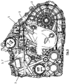
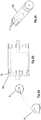
- FIG. 1 A hybrid transmission according to the invention for a motor vehicle is shown from the side.
- the hybrid transmission comprises a transmission housing 1, a differential 2 arranged in the transmission housing 1 with a ring gear 4 and an electric motor 3 arranged in the transmission housing 1.
- the electric motor 3 and the ring gear 4 have mutually parallel axes.
- oil is collected in an oil sump, not shown.
- the ring gear 4 of the differential 2 is partially arranged in the oil sump so that it can take oil from the oil sump and fling it upwards.
- a collecting device 5 is arranged in the gear housing 1 above and laterally offset from the ring gear 4, so that oil is thrown out of the oil sump by the ring gear 4 in the collecting device 5, more precisely in a first collecting area 6 of the collecting device 5, and is passed on from the collecting device 5 to the electric motor 3 in order to cool the electric motor 3.
- the electric motor 3 comprises a hollow shaft rotor and the collecting device 5 conducts the oil to the hollow shaft rotor of the electric motor 3 in order to feed the electric motor rotor with oil through the hollow shaft rotor.
- the collecting device 5 has a first collecting area 6 at a first end of the collecting device 5 facing the ring gear 4, which is shown in FIGS Fig. 2 is shown in detail. Furthermore, the collecting device 5 can have a second collecting area, at the second end of the collecting device 5 opposite the first end and facing the electric motor 3. The oil can flow from the second collecting area into the hollow shaft rotor or into an antechamber of the hollow shaft rotor, in particular fall.
- the depth, precise design and inclined position of the collecting device 5, in particular its first collecting area 6, serves to optimally collect and pass on the oil to the electric motor 3 and at the same time to prevent the oil from returning when inclined, for example when driving downhill heavily.
- the collecting device 5 comprises a central part 7 between the first collecting area 6 and the second collecting area, which can be designed as a tube, hose or bore and which can have a diameter of a few mm - see above Fig. 5 ,
- the middle part 7 can be formed by a long bore through the thickened gear housing 1.
- the collecting device 5 has at its first collecting area 6 a first opening 8 for receiving oil, in particular spray oil, from the area of the ring gear 4 and a second opening 9 for receiving oil, in particular spray oil, from the area of a clutch of the hybrid transmission, for example at least one clutch of a dual clutch transmission.
- the outlet 17 of the first collecting area 6 can be connected to the electric motor 3 via an internal part such as a hose or a tube or via a long bore through the thickened gear housing 1.
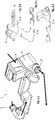
- Fig. 2 a The possible inflow and outflow of oil into the first collection area 6 is shown in Fig. 2 a represented by thick arrows.
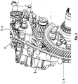
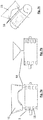
- Fig. 3 is a three-dimensional partial representation of the same hybrid transmission according to the invention
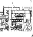
- Fig. 1 and Fig. 4 shows the hybrid transmission in a partial sectional view from above.
- Fig. 5 shows the hybrid transmission of the Fig. 1 seen from the opposite side.
- the middle part 7 of the collecting device 5 runs easily inclined downwards to the electric motor 3 such that an outlet above the hollow shaft rotor of the electric motor 3 is possible.
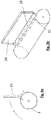
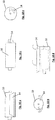
- FIGS. 6 to 10 show training of the electric motor housing 10 and the gear housing 1, which serve to improve the passive cooling of the electric motor 3.
- the direction of movement of the oil, in particular spray oil, is shown in part by arrows.
- the electric motor housing 10 Since the thermal hot spots, namely the winding heads of the electric motor 3 are to be cooled, the electric motor housing 10, as in FIG 6 b and c shown, radial recesses at the level of the winding heads through which the cooling oil sprayed from the differential 2 and from other shafts reaches the electric motor 3. All shafts are aligned coaxially to the rotor of the electric motor 3, so that the splash oil of the differential 2 and other gear components strikes the housing 10 radially at least on the side facing the electric motor 3.
- the gear housing 1 can have geometric structures which are designed to direct oil reaching the gear housing 1 to the electric motor 3, in particular in order to direct the oil into the recesses 11 to the winding heads.
- ribs 15, for example baffle plates, are formed on the transmission housing 1, which can have one or more recesses in the installed position above the cutouts 11, so that the oil runs along the rib 15 or the sheet metal to the cutout 11. Falling oil drops 18 are shown schematically.
- fastening structures 16 of the transmission housing can also be used as oil guide plates or ribs.
- the outer side of the electric motor housing 10 can also have geometric structures which are designed to direct oil reaching the electric motor housing 10 into the cutouts 11.
- Such geometric structures can be, for example, ribs 12 which run obliquely towards the cutouts 11 and / or grooves 13 which run around the electric motor housing 10 and have bores in the grooves 13 as cutouts 11 for the oil to run through.
- oil guide plates 14 on the electric motor housing 10, in particular on the side of the electric motor 3 facing away from the differential 2 can also be used in order to guide the oil into recesses 11.
- oil guide plate bores 19 can be provided on the oil guide plate 14 in order to allow the oil to run down onto the electric motor 3 also on the rear side of the oil guide plate 14.
Landscapes
- Engineering & Computer Science (AREA)
- General Engineering & Computer Science (AREA)
- Mechanical Engineering (AREA)
- Chemical & Material Sciences (AREA)
- Combustion & Propulsion (AREA)
- Transportation (AREA)
- Electric Propulsion And Braking For Vehicles (AREA)
- General Details Of Gearings (AREA)
- Hybrid Electric Vehicles (AREA)
- Motor Or Generator Cooling System (AREA)
Applications Claiming Priority (1)
| Application Number | Priority Date | Filing Date | Title |
|---|---|---|---|
| DE102018213990.3A DE102018213990B3 (de) | 2018-08-20 | 2018-08-20 | Hybridgetriebe |
Publications (2)
| Publication Number | Publication Date |
|---|---|
| EP3614022A1 true EP3614022A1 (fr) | 2020-02-26 |
| EP3614022B1 EP3614022B1 (fr) | 2021-07-28 |
Family
ID=67070627
Family Applications (1)
| Application Number | Title | Priority Date | Filing Date |
|---|---|---|---|
| EP19182285.7A Active EP3614022B1 (fr) | 2018-08-20 | 2019-06-25 | Transmission hybride |
Country Status (3)
| Country | Link |
|---|---|
| EP (1) | EP3614022B1 (fr) |
| CN (1) | CN110848374B (fr) |
| DE (1) | DE102018213990B3 (fr) |
Cited By (2)
| Publication number | Priority date | Publication date | Assignee | Title |
|---|---|---|---|---|
| CN115325147A (zh) * | 2021-05-10 | 2022-11-11 | 上汽通用汽车有限公司 | 冷却系统、变速箱和汽车 |
| RU2856518C2 (ru) * | 2023-09-21 | 2026-02-24 | Чери Отомобайл Ко., Лтд. | Маслоотражатель гибридной трансмиссии, гибридная трансмиссия и транспортное средство |
Families Citing this family (3)
| Publication number | Priority date | Publication date | Assignee | Title |
|---|---|---|---|---|
| CN113494594B (zh) * | 2021-06-25 | 2023-01-06 | 东风汽车有限公司东风日产乘用车公司 | 用于新能源混动变速器的润滑系统 |
| DE102021206607B3 (de) | 2021-06-25 | 2022-10-20 | Vitesco Technologies Germany Gmbh | Ölverteiler, Achsantrieb und Kraftfahrzeug |
| CN115199732A (zh) * | 2022-07-19 | 2022-10-18 | 东风汽车集团股份有限公司 | 一种壳体总成、混合动力式驱动系统及车辆 |
Citations (4)
| Publication number | Priority date | Publication date | Assignee | Title |
|---|---|---|---|---|
| JP4346764B2 (ja) * | 1999-12-28 | 2009-10-21 | 本田技研工業株式会社 | 電動モータのロータ軸受の潤滑構造 |
| US8074753B2 (en) * | 2005-10-26 | 2011-12-13 | Toyota Jidosha Kabushiki Kaisha | Drive device of vehicle |
| US20120091836A1 (en) * | 2009-04-08 | 2012-04-19 | Toyota Jidosha Kabushiki Kaisha | Heat-generating portion cooling structure of vehicle drive apparatus |
| EP2479053A1 (fr) * | 2011-01-24 | 2012-07-25 | Kanzaki Kokyukoki Mfg. Co., Ltd. | Boîte-pont électrique |
Family Cites Families (9)
| Publication number | Priority date | Publication date | Assignee | Title |
|---|---|---|---|---|
| JP2004180477A (ja) | 2002-11-29 | 2004-06-24 | Honda Motor Co Ltd | 前後輪駆動車両におけるモータの冷却構造 |
| JP2005083491A (ja) | 2003-09-09 | 2005-03-31 | Toyota Motor Corp | キャッチタンク |
| JP4497113B2 (ja) | 2006-03-16 | 2010-07-07 | トヨタ自動車株式会社 | ハイブリッド車両 |
| US20080135339A1 (en) * | 2006-11-17 | 2008-06-12 | Miller Kent A | Method and apparatus for cooling and lubricating an off-axis motor/generator |
| JP2008286247A (ja) | 2007-05-15 | 2008-11-27 | Toyota Motor Corp | オイルレベル調整装置 |
| JP2011007208A (ja) * | 2009-06-23 | 2011-01-13 | Aisin Ai Co Ltd | 変速機 |
| DE102014209056A1 (de) * | 2014-05-14 | 2015-11-19 | Zf Friedrichshafen Ag | Hybridantriebsanordnung eines Kraftfahrzeuges |
| JP6138106B2 (ja) * | 2014-11-27 | 2017-05-31 | アイシン精機株式会社 | 減速機の潤滑構造 |
| KR101916075B1 (ko) * | 2016-12-09 | 2018-11-07 | 현대자동차 주식회사 | 변속기 케이스의 윤활구조 |
-
2018
- 2018-08-20 DE DE102018213990.3A patent/DE102018213990B3/de active Active
-
2019
- 2019-06-25 EP EP19182285.7A patent/EP3614022B1/fr active Active
- 2019-08-19 CN CN201910763997.9A patent/CN110848374B/zh active Active
Patent Citations (4)
| Publication number | Priority date | Publication date | Assignee | Title |
|---|---|---|---|---|
| JP4346764B2 (ja) * | 1999-12-28 | 2009-10-21 | 本田技研工業株式会社 | 電動モータのロータ軸受の潤滑構造 |
| US8074753B2 (en) * | 2005-10-26 | 2011-12-13 | Toyota Jidosha Kabushiki Kaisha | Drive device of vehicle |
| US20120091836A1 (en) * | 2009-04-08 | 2012-04-19 | Toyota Jidosha Kabushiki Kaisha | Heat-generating portion cooling structure of vehicle drive apparatus |
| EP2479053A1 (fr) * | 2011-01-24 | 2012-07-25 | Kanzaki Kokyukoki Mfg. Co., Ltd. | Boîte-pont électrique |
Cited By (2)
| Publication number | Priority date | Publication date | Assignee | Title |
|---|---|---|---|---|
| CN115325147A (zh) * | 2021-05-10 | 2022-11-11 | 上汽通用汽车有限公司 | 冷却系统、变速箱和汽车 |
| RU2856518C2 (ru) * | 2023-09-21 | 2026-02-24 | Чери Отомобайл Ко., Лтд. | Маслоотражатель гибридной трансмиссии, гибридная трансмиссия и транспортное средство |
Also Published As
| Publication number | Publication date |
|---|---|
| DE102018213990B3 (de) | 2019-09-05 |
| EP3614022B1 (fr) | 2021-07-28 |
| CN110848374B (zh) | 2023-06-13 |
| CN110848374A (zh) | 2020-02-28 |
Similar Documents
| Publication | Publication Date | Title |
|---|---|---|
| DE102007020453B4 (de) | Getriebe, Schmiermittel-Kreislaufsystem und Getriebebaureihe | |
| DE102008017488C5 (de) | Lagerdeckel, Getriebe und Baureihe | |
| EP3614022A1 (fr) | Transmission hybride | |
| DE102019128957A1 (de) | Schmiermittelversorgungseinrichtung für ein Kraftfahrzeug, Verfahren zum Betreiben einer solchen Schmiermittelversorgungseinrichtung sowie Kraftfahrzeug mit einer solchen Schmiermittelversorgungseinrichtung | |
| DE102012024699A1 (de) | Kupplungsanordnung mit einer Doppelkupplungseinrichtung | |
| EP4302000B1 (fr) | Système d'alimentation en lubrifiant pour unité d'entraînement d'un véhicule électrique | |
| WO2013050182A1 (fr) | Dispositif de transmission électromotorisé | |
| DE102018211360A1 (de) | Schmiermittelversorgungssystem für eine Antriebsvorrichtung eines elektrisch betriebenen Fahrzeugs | |
| DE102021128081A1 (de) | Kühlmittelversorgung für einen elektrischen Fahrzeugachsantrieb | |
| DE102011055192A1 (de) | Generatoreinheit | |
| DE102014204088A1 (de) | Ölführung eines Getriebes für ein Fahrzeug | |
| DE102018211359B4 (de) | Schmiermittelversorgungssystem für eine Antriebsvorrichtung eines elektrisch betriebenen Fahrzeugs | |
| DE102021207713B3 (de) | Antriebseinheit | |
| DE102018211356A1 (de) | Schmiermittelversorgungssystem für eine Antriebsvorrichtung eines elektrisch betriebenen Fahrzeugs | |
| DE102011112253A1 (de) | Baueinheit für ein Triebwerk eines Luftfahrzeugs | |
| DE102021128068A1 (de) | Kühlmittelversorgungssystem für eine elektrisch betriebene Fahrzeugachse | |
| DE102015218748B4 (de) | Hybridantriebsmodul für ein Kraftfahrzeug | |
| DE102020203984B4 (de) | Ölversorgungssystem eines Fahrzeuggetriebes | |
| EP3693635B1 (fr) | Groupe motopropulseur pour un véhicule, en particulier pour un véhicule automobile | |
| DE102021128067A1 (de) | Kühlmittelversorgungssystem für eine elektrisch betriebene Fahrzeugachse | |
| WO2016041897A1 (fr) | Moyen de guidage destiné à être disposé au niveau d'une boîte de vitesses et/ou d'un embrayage d'un véhicule automobile | |
| DE102021117504A1 (de) | Kühlmittelversorgungssystem für eine Antriebsvorrichtung eines elektrisch betriebenen Fahrzeugs | |
| DE102021205678A1 (de) | Antriebsanordnung für ein Kraftfahrzeug | |
| EP0485442B1 (fr) | Boite de vitesses pour vehicule a moteur a deux essieux moteurs | |
| DE102016224360A1 (de) | Entlüfter, Fahrzeuggetriebe sowie Kraftfahrzeug |
Legal Events
| Date | Code | Title | Description |
|---|---|---|---|
| PUAI | Public reference made under article 153(3) epc to a published international application that has entered the european phase |
Free format text: ORIGINAL CODE: 0009012 |
|
| STAA | Information on the status of an ep patent application or granted ep patent |
Free format text: STATUS: THE APPLICATION HAS BEEN PUBLISHED |
|
| AK | Designated contracting states |
Kind code of ref document: A1 Designated state(s): AL AT BE BG CH CY CZ DE DK EE ES FI FR GB GR HR HU IE IS IT LI LT LU LV MC MK MT NL NO PL PT RO RS SE SI SK SM TR |
|
| AX | Request for extension of the european patent |
Extension state: BA ME |
|
| STAA | Information on the status of an ep patent application or granted ep patent |
Free format text: STATUS: REQUEST FOR EXAMINATION WAS MADE |
|
| 17P | Request for examination filed |
Effective date: 20200409 |
|
| RBV | Designated contracting states (corrected) |
Designated state(s): AL AT BE BG CH CY CZ DE DK EE ES FI FR GB GR HR HU IE IS IT LI LT LU LV MC MK MT NL NO PL PT RO RS SE SI SK SM TR |
|
| STAA | Information on the status of an ep patent application or granted ep patent |
Free format text: STATUS: EXAMINATION IS IN PROGRESS |
|
| 17Q | First examination report despatched |
Effective date: 20200728 |
|
| GRAP | Despatch of communication of intention to grant a patent |
Free format text: ORIGINAL CODE: EPIDOSNIGR1 |
|
| STAA | Information on the status of an ep patent application or granted ep patent |
Free format text: STATUS: GRANT OF PATENT IS INTENDED |
|
| INTG | Intention to grant announced |
Effective date: 20210305 |
|
| GRAS | Grant fee paid |
Free format text: ORIGINAL CODE: EPIDOSNIGR3 |
|
| GRAA | (expected) grant |
Free format text: ORIGINAL CODE: 0009210 |
|
| STAA | Information on the status of an ep patent application or granted ep patent |
Free format text: STATUS: THE PATENT HAS BEEN GRANTED |
|
| AK | Designated contracting states |
Kind code of ref document: B1 Designated state(s): AL AT BE BG CH CY CZ DE DK EE ES FI FR GB GR HR HU IE IS IT LI LT LU LV MC MK MT NL NO PL PT RO RS SE SI SK SM TR |
|
| REG | Reference to a national code |
Ref country code: GB Ref legal event code: FG4D Free format text: NOT ENGLISH |
|
| REG | Reference to a national code |
Ref country code: CH Ref legal event code: EP |
|
| REG | Reference to a national code |
Ref country code: DE Ref legal event code: R096 Ref document number: 502019001898 Country of ref document: DE |
|
| REG | Reference to a national code |
Ref country code: AT Ref legal event code: REF Ref document number: 1415007 Country of ref document: AT Kind code of ref document: T Effective date: 20210815 |
|
| REG | Reference to a national code |
Ref country code: IE Ref legal event code: FG4D Free format text: LANGUAGE OF EP DOCUMENT: GERMAN |
|
| REG | Reference to a national code |
Ref country code: LT Ref legal event code: MG9D |
|
| REG | Reference to a national code |
Ref country code: NL Ref legal event code: MP Effective date: 20210728 |
|
| PG25 | Lapsed in a contracting state [announced via postgrant information from national office to epo] |
Ref country code: SE Free format text: LAPSE BECAUSE OF FAILURE TO SUBMIT A TRANSLATION OF THE DESCRIPTION OR TO PAY THE FEE WITHIN THE PRESCRIBED TIME-LIMIT Effective date: 20210728 Ref country code: RS Free format text: LAPSE BECAUSE OF FAILURE TO SUBMIT A TRANSLATION OF THE DESCRIPTION OR TO PAY THE FEE WITHIN THE PRESCRIBED TIME-LIMIT Effective date: 20210728 Ref country code: FI Free format text: LAPSE BECAUSE OF FAILURE TO SUBMIT A TRANSLATION OF THE DESCRIPTION OR TO PAY THE FEE WITHIN THE PRESCRIBED TIME-LIMIT Effective date: 20210728 Ref country code: ES Free format text: LAPSE BECAUSE OF FAILURE TO SUBMIT A TRANSLATION OF THE DESCRIPTION OR TO PAY THE FEE WITHIN THE PRESCRIBED TIME-LIMIT Effective date: 20210728 Ref country code: LT Free format text: LAPSE BECAUSE OF FAILURE TO SUBMIT A TRANSLATION OF THE DESCRIPTION OR TO PAY THE FEE WITHIN THE PRESCRIBED TIME-LIMIT Effective date: 20210728 Ref country code: BG Free format text: LAPSE BECAUSE OF FAILURE TO SUBMIT A TRANSLATION OF THE DESCRIPTION OR TO PAY THE FEE WITHIN THE PRESCRIBED TIME-LIMIT Effective date: 20211028 Ref country code: HR Free format text: LAPSE BECAUSE OF FAILURE TO SUBMIT A TRANSLATION OF THE DESCRIPTION OR TO PAY THE FEE WITHIN THE PRESCRIBED TIME-LIMIT Effective date: 20210728 Ref country code: NO Free format text: LAPSE BECAUSE OF FAILURE TO SUBMIT A TRANSLATION OF THE DESCRIPTION OR TO PAY THE FEE WITHIN THE PRESCRIBED TIME-LIMIT Effective date: 20211028 Ref country code: PT Free format text: LAPSE BECAUSE OF FAILURE TO SUBMIT A TRANSLATION OF THE DESCRIPTION OR TO PAY THE FEE WITHIN THE PRESCRIBED TIME-LIMIT Effective date: 20211129 Ref country code: NL Free format text: LAPSE BECAUSE OF FAILURE TO SUBMIT A TRANSLATION OF THE DESCRIPTION OR TO PAY THE FEE WITHIN THE PRESCRIBED TIME-LIMIT Effective date: 20210728 |
|
| PG25 | Lapsed in a contracting state [announced via postgrant information from national office to epo] |
Ref country code: PL Free format text: LAPSE BECAUSE OF FAILURE TO SUBMIT A TRANSLATION OF THE DESCRIPTION OR TO PAY THE FEE WITHIN THE PRESCRIBED TIME-LIMIT Effective date: 20210728 Ref country code: LV Free format text: LAPSE BECAUSE OF FAILURE TO SUBMIT A TRANSLATION OF THE DESCRIPTION OR TO PAY THE FEE WITHIN THE PRESCRIBED TIME-LIMIT Effective date: 20210728 Ref country code: GR Free format text: LAPSE BECAUSE OF FAILURE TO SUBMIT A TRANSLATION OF THE DESCRIPTION OR TO PAY THE FEE WITHIN THE PRESCRIBED TIME-LIMIT Effective date: 20211029 |
|
| PG25 | Lapsed in a contracting state [announced via postgrant information from national office to epo] |
Ref country code: DK Free format text: LAPSE BECAUSE OF FAILURE TO SUBMIT A TRANSLATION OF THE DESCRIPTION OR TO PAY THE FEE WITHIN THE PRESCRIBED TIME-LIMIT Effective date: 20210728 |
|
| REG | Reference to a national code |
Ref country code: DE Ref legal event code: R097 Ref document number: 502019001898 Country of ref document: DE |
|
| PG25 | Lapsed in a contracting state [announced via postgrant information from national office to epo] |
Ref country code: SM Free format text: LAPSE BECAUSE OF FAILURE TO SUBMIT A TRANSLATION OF THE DESCRIPTION OR TO PAY THE FEE WITHIN THE PRESCRIBED TIME-LIMIT Effective date: 20210728 Ref country code: SK Free format text: LAPSE BECAUSE OF FAILURE TO SUBMIT A TRANSLATION OF THE DESCRIPTION OR TO PAY THE FEE WITHIN THE PRESCRIBED TIME-LIMIT Effective date: 20210728 Ref country code: RO Free format text: LAPSE BECAUSE OF FAILURE TO SUBMIT A TRANSLATION OF THE DESCRIPTION OR TO PAY THE FEE WITHIN THE PRESCRIBED TIME-LIMIT Effective date: 20210728 Ref country code: EE Free format text: LAPSE BECAUSE OF FAILURE TO SUBMIT A TRANSLATION OF THE DESCRIPTION OR TO PAY THE FEE WITHIN THE PRESCRIBED TIME-LIMIT Effective date: 20210728 Ref country code: CZ Free format text: LAPSE BECAUSE OF FAILURE TO SUBMIT A TRANSLATION OF THE DESCRIPTION OR TO PAY THE FEE WITHIN THE PRESCRIBED TIME-LIMIT Effective date: 20210728 Ref country code: AL Free format text: LAPSE BECAUSE OF FAILURE TO SUBMIT A TRANSLATION OF THE DESCRIPTION OR TO PAY THE FEE WITHIN THE PRESCRIBED TIME-LIMIT Effective date: 20210728 |
|
| PLBE | No opposition filed within time limit |
Free format text: ORIGINAL CODE: 0009261 |
|
| STAA | Information on the status of an ep patent application or granted ep patent |
Free format text: STATUS: NO OPPOSITION FILED WITHIN TIME LIMIT |
|
| 26N | No opposition filed |
Effective date: 20220429 |
|
| PG25 | Lapsed in a contracting state [announced via postgrant information from national office to epo] |
Ref country code: IT Free format text: LAPSE BECAUSE OF FAILURE TO SUBMIT A TRANSLATION OF THE DESCRIPTION OR TO PAY THE FEE WITHIN THE PRESCRIBED TIME-LIMIT Effective date: 20210728 |
|
| PG25 | Lapsed in a contracting state [announced via postgrant information from national office to epo] |
Ref country code: MC Free format text: LAPSE BECAUSE OF FAILURE TO SUBMIT A TRANSLATION OF THE DESCRIPTION OR TO PAY THE FEE WITHIN THE PRESCRIBED TIME-LIMIT Effective date: 20210728 |
|
| REG | Reference to a national code |
Ref country code: CH Ref legal event code: PL |
|
| REG | Reference to a national code |
Ref country code: BE Ref legal event code: MM Effective date: 20220630 |
|
| PG25 | Lapsed in a contracting state [announced via postgrant information from national office to epo] |
Ref country code: LU Free format text: LAPSE BECAUSE OF NON-PAYMENT OF DUE FEES Effective date: 20220625 Ref country code: LI Free format text: LAPSE BECAUSE OF NON-PAYMENT OF DUE FEES Effective date: 20220630 Ref country code: IE Free format text: LAPSE BECAUSE OF NON-PAYMENT OF DUE FEES Effective date: 20220625 Ref country code: FR Free format text: LAPSE BECAUSE OF NON-PAYMENT OF DUE FEES Effective date: 20220630 Ref country code: CH Free format text: LAPSE BECAUSE OF NON-PAYMENT OF DUE FEES Effective date: 20220630 |
|
| PG25 | Lapsed in a contracting state [announced via postgrant information from national office to epo] |
Ref country code: BE Free format text: LAPSE BECAUSE OF NON-PAYMENT OF DUE FEES Effective date: 20220630 |
|
| GBPC | Gb: european patent ceased through non-payment of renewal fee |
Effective date: 20230625 |
|
| PG25 | Lapsed in a contracting state [announced via postgrant information from national office to epo] |
Ref country code: MK Free format text: LAPSE BECAUSE OF FAILURE TO SUBMIT A TRANSLATION OF THE DESCRIPTION OR TO PAY THE FEE WITHIN THE PRESCRIBED TIME-LIMIT Effective date: 20210728 Ref country code: CY Free format text: LAPSE BECAUSE OF FAILURE TO SUBMIT A TRANSLATION OF THE DESCRIPTION OR TO PAY THE FEE WITHIN THE PRESCRIBED TIME-LIMIT Effective date: 20210728 Ref country code: GB Free format text: LAPSE BECAUSE OF NON-PAYMENT OF DUE FEES Effective date: 20230625 |
|
| PG25 | Lapsed in a contracting state [announced via postgrant information from national office to epo] |
Ref country code: HU Free format text: LAPSE BECAUSE OF FAILURE TO SUBMIT A TRANSLATION OF THE DESCRIPTION OR TO PAY THE FEE WITHIN THE PRESCRIBED TIME-LIMIT; INVALID AB INITIO Effective date: 20190625 |
|
| PG25 | Lapsed in a contracting state [announced via postgrant information from national office to epo] |
Ref country code: TR Free format text: LAPSE BECAUSE OF FAILURE TO SUBMIT A TRANSLATION OF THE DESCRIPTION OR TO PAY THE FEE WITHIN THE PRESCRIBED TIME-LIMIT Effective date: 20210728 |
|
| PG25 | Lapsed in a contracting state [announced via postgrant information from national office to epo] |
Ref country code: MT Free format text: LAPSE BECAUSE OF FAILURE TO SUBMIT A TRANSLATION OF THE DESCRIPTION OR TO PAY THE FEE WITHIN THE PRESCRIBED TIME-LIMIT Effective date: 20210728 |
|
| REG | Reference to a national code |
Ref country code: DE Ref legal event code: R082 Ref document number: 502019001898 Country of ref document: DE Representative=s name: EULER, MATTHIAS, DR., DE |
|
| PGFP | Annual fee paid to national office [announced via postgrant information from national office to epo] |
Ref country code: DE Payment date: 20250618 Year of fee payment: 7 |
|
| REG | Reference to a national code |
Ref country code: AT Ref legal event code: MM01 Ref document number: 1415007 Country of ref document: AT Kind code of ref document: T Effective date: 20240625 |
|
| REG | Reference to a national code |
Ref country code: DE Ref legal event code: R081 Ref document number: 502019001898 Country of ref document: DE Owner name: MAGNA PT B.V. & CO. KGAA, DE Free format text: FORMER OWNER: MAGNA PT B.V. & CO. KG, 74199 UNTERGRUPPENBACH, DE |
|
| PG25 | Lapsed in a contracting state [announced via postgrant information from national office to epo] |
Ref country code: AT Free format text: LAPSE BECAUSE OF NON-PAYMENT OF DUE FEES Effective date: 20240625 |
|
| PGFP | Annual fee paid to national office [announced via postgrant information from national office to epo] |
Ref country code: AT Payment date: 20260410 Year of fee payment: 5 |