EP3614030B1 - Élément de conduite pourvu de support intégré pour un moyen de fixation - Google Patents
Élément de conduite pourvu de support intégré pour un moyen de fixation Download PDFInfo
- Publication number
- EP3614030B1 EP3614030B1 EP19183534.7A EP19183534A EP3614030B1 EP 3614030 B1 EP3614030 B1 EP 3614030B1 EP 19183534 A EP19183534 A EP 19183534A EP 3614030 B1 EP3614030 B1 EP 3614030B1
- Authority
- EP
- European Patent Office
- Prior art keywords
- holder
- conduit
- conduit element
- fixing means
- line
- Prior art date
- Legal status (The legal status is an assumption and is not a legal conclusion. Google has not performed a legal analysis and makes no representation as to the accuracy of the status listed.)
- Active
Links
Images

Classifications
-
- F—MECHANICAL ENGINEERING; LIGHTING; HEATING; WEAPONS; BLASTING
- F16—ENGINEERING ELEMENTS AND UNITS; GENERAL MEASURES FOR PRODUCING AND MAINTAINING EFFECTIVE FUNCTIONING OF MACHINES OR INSTALLATIONS; THERMAL INSULATION IN GENERAL
- F16L—PIPES; JOINTS OR FITTINGS FOR PIPES; SUPPORTS FOR PIPES, CABLES OR PROTECTIVE TUBING; MEANS FOR THERMAL INSULATION IN GENERAL
- F16L47/00—Connecting arrangements or other fittings specially adapted to be made of plastics or to be used with pipes made of plastics
- F16L47/06—Connecting arrangements or other fittings specially adapted to be made of plastics or to be used with pipes made of plastics with sleeve or socket formed by or in the pipe end
- F16L47/12—Connecting arrangements or other fittings specially adapted to be made of plastics or to be used with pipes made of plastics with sleeve or socket formed by or in the pipe end with additional locking means
-
- F—MECHANICAL ENGINEERING; LIGHTING; HEATING; WEAPONS; BLASTING
- F16—ENGINEERING ELEMENTS AND UNITS; GENERAL MEASURES FOR PRODUCING AND MAINTAINING EFFECTIVE FUNCTIONING OF MACHINES OR INSTALLATIONS; THERMAL INSULATION IN GENERAL
- F16L—PIPES; JOINTS OR FITTINGS FOR PIPES; SUPPORTS FOR PIPES, CABLES OR PROTECTIVE TUBING; MEANS FOR THERMAL INSULATION IN GENERAL
- F16L21/00—Joints with sleeve or socket
- F16L21/06—Joints with sleeve or socket with a divided sleeve or ring clamping around the pipe ends
-
- F—MECHANICAL ENGINEERING; LIGHTING; HEATING; WEAPONS; BLASTING
- F16—ENGINEERING ELEMENTS AND UNITS; GENERAL MEASURES FOR PRODUCING AND MAINTAINING EFFECTIVE FUNCTIONING OF MACHINES OR INSTALLATIONS; THERMAL INSULATION IN GENERAL
- F16L—PIPES; JOINTS OR FITTINGS FOR PIPES; SUPPORTS FOR PIPES, CABLES OR PROTECTIVE TUBING; MEANS FOR THERMAL INSULATION IN GENERAL
- F16L33/00—Arrangements for connecting hoses to rigid members; Rigid hose-connectors, i.e. single members engaging both hoses
- F16L33/02—Hose-clips
Definitions
- the invention relates to a line element, in particular for air conditioning systems, according to the preamble of claim 1.
- the invention also relates to a connection arrangement comprising such a line element as well as a second line element and a circumferential fixing means for fixing the second line element to the first line element.
- the invention also relates to a method for producing such a line element.
- Such a line element is, for example, from JP 4 842055 B2 or the EP 0 284 468 A1 known.
- Air-carrying duct systems for the air conditioning of rail vehicles, other vehicles or generally for the air conditioning of rooms are usually made up of several duct elements. These sections of the line must be tightly connected to one another, which usually requires an additional fixing agent that must be inserted, positioned and closed.
- a fixing means for example a pipe clamp
- the fixing means is positioned in a cross section that does not have a complete overlap of the line elements, no jamming and thus no tight connection of the channel pieces will be achieved.
- the task is to simplify the positioning and connection of line elements and to reduce the risk of incorrect assembly.
- a line element comprising a first line end, wherein at least one holder is arranged on a radial outside of the first line end, the holder being designed to at least partially accommodate an end face of a second line end of a second line element, the holder further is designed to at least partially accommodate a fixing means running around the first line end, a receiving space being arranged in the radial direction between the at least one holder and the radial outside of the first line end, which is designed to at least partially accommodate the second line end of the second line element, and wherein a guide space is arranged in the holder, which is designed to at least partially accommodate the fixation means and to define an axial target position between the first line end and the fixation means, furthermore the guide space being radially outside the receiving space and essentially at the same axial position how the receiving space is arranged, the holder has a first axially extending section, with which it is fastened to the radial outside, a subsequent radially outwardly extending
- Section passes over, and comprises a subsequent radially outwardly extending curve, which forms the guide space and ends in a retaining mechanism.
- the receiving space is the space between the radial outside of the first line end and the second axially extending section.
- the fixing means can be pre-assembled on the line element.
- the fixing means can be, for example, a clamp, a pipe clamp, a hose clamp or a cable tie.
- the fixing means is automatically positioned at the ideal axial distance from the end of the cable end, thereby avoiding incorrect positioning.
- the torque applied can lead to an unwanted inclination or displacement of the fixing means relative to the end of the line, which can be avoided by the solution according to the invention.
- the at least one holder can also define a substantially optimal axial relative position of the first line end to the second line end.
- the fitter can more easily determine whether, for example, the second end of the line has been pushed far enough onto the first end of the line to provide a sufficiently wide overlap area.
- an inner radius of the second line end is then at least as large as an outer radius of the first line end.
- one or both line ends can have one or more sealing lips which protrude in the radial direction onto the other line end. This means that tolerances can be compensated for and a tight connection between the line elements can still be achieved.
- axial direction or radial direction essentially means the longitudinal axis of a cylindrical line end or the directions perpendicular to this longitudinal axis.
- a substantially cylindrical line end is understood to mean a line end whose cross section remains the same along the longitudinal axis of this line end.
- the cross section in this essentially cylindrical line end can be described by a closed border line (e.g. circle, ellipse), which preferably has a curvature in the same direction or straight sections at every point.
- a substantially cylindrical line end is to be understood as meaning a convex curvature of the outside of the line end.
- the line element can have a non-cylindrical cross-section at a certain distance from the first line end, or can bend or branch, etc.
- Essentially cylindrical is also to be understood as meaning that certain deviations from an ideal cylindrical shape are unavoidable due to tolerances and furthermore due to elastic deformations , especially when the line element is not assembled, deviations are possible.
- the line element can include one, two, three, four or more holders. If there are two or more holders, these are preferably arranged at the same axial position at the first end of the line.
- the line element is preferably intended for a duct system of an air conditioning system and is dimensioned accordingly.
- the second line element can be a standard line element without a holder or can only have no holders at its second line end.
- the line element can be manufactured with integrated holders using additive processes.
- the solution according to the invention achieves increased reliability in the connection of the line elements through the controllability of the overlap (holder serves as a stop) and the correct positioning of the clamp/pipe clamp/hose clamp/cable tie.
- the holder for the fixing agent integrated into the component enables pre-assembly, simplifies logistics (fewer components), speeds up final assembly and reduces costs.
- the fixing agent can simply be pressed into the holder(s) and does not need to be threaded.
- a simple cable tie can also be used as a fixing means, which is easier to open and close and costs less than the clamps common in the prior art. Cable ties are generally suitable for a larger range of cable diameters than clamps and are therefore more flexible in use.
- the line element preferably comprises at least two holders, the holders being at the same distance from the holders adjacent in the circumferential direction. With two holders, these are arranged at a distance of 180° (center of one holder to the center of the other holder) in the circumferential direction. With three holders, these are arranged at a distance of 120° (center of one holder to the center of the adjacent holder) in the circumferential direction, etc. This allows the most effective pre-positioning of the fixing means and the most precise desired axial relative position for the two line ends to be defined.
- a receiving space is arranged in the radial direction between the at least one holder and the radial outside of the first line end, which is designed to at least partially accommodate the second line end of the second line element.
- the second line end can then rest radially on the inside of the first line end and radially on the outside of the holder.
- a stop for the end face of the second line end of the second line element is arranged at an axial end of the receiving space and defines an axial target position between the second line element and the first line element.
- a guide space is arranged in the holder and is designed to at least partially accommodate the fixing means and to define an axial target position between the first line end and the fixing means.
- the guide space is arranged radially outside the receiving space and essentially at the same axial position as the receiving space.
- the fixing means can thus fix the two line ends to one another as effectively as possible and the best possible relative arrangement of the three parts is ensured.
- the holder preferably has a retaining mechanism for a fixing means introduced into the guide space at an end of the guide space that is open in the axial direction.
- the retaining mechanism ensures that once a fixation means has been inserted, it cannot easily leave the guide space, thus preventing the loss of a pre-assembled fixation means.
- the retaining mechanism can be, for example, an elastic clip mechanism that forms a narrowed open end of the guide space in the axial direction. This also simplifies the introduction of the fixing agent during pre-assembly.
- connection arrangement which comprises a line element according to one of the above embodiments as well as a second line element and a circumferential fixing means for fixing the second line element to the first line element.
- the fixing means is preferably a clamp, a pipe clamp, a hose clamp or a cable tie.
- a cable tie is sufficient according to the invention. This is achieved in that the at least one holder itself ensures good positioning, which would be difficult to achieve using a cable tie in the prior art.
- the cable tie can be made of plastic and/or metal.
- a cable tie has the further advantage that it can be tightened very quickly with standard pliers and can also be loosened again using side cutters if this is necessary.
- the object according to the invention is also achieved by a method for producing a line element according to one of the above embodiments, wherein the at least one holder is applied to the first line end by an additive manufacturing process, whereby the first line element is obtained.
- a standard line element can be used as a basis on which the holder(s) is/are applied using an additive process. This makes it possible to add holders for each standard line element in order to obtain a line element according to the invention.
- the line element with at least one integrated holder is manufactured using an additive manufacturing process.
- the line element can also be manufactured in one piece together with the holder(s) using an additive manufacturing process, such as 3D printing.
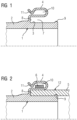
- Figure 2 shows a sectional view through a connection area of a connection arrangement according to the invention in the assembled state, while Figure 1 and 3 only shows part of a line element 1 according to the invention alone.
- Figure 1 shows the line element 1 and in particular a first line end 2 of the line element 1.
- At least one holder 4 is arranged on a radial outside 3 of the first line end 2.
- the holder 4 is designed to hold an end face of a second line end 5 (see Figure 2 ) of a second line element 12 at least partially.
- the holder 4 is designed to have a fixing means 6 (see Figure 2 ) to be recorded at least partially.
- the fixing means 6 can be, for example, a clamp, a pipe clamp, a hose clamp or a cable tie. As a result of the pre-assembly, the fixing means 6 is automatically positioned at the ideal axial distance from the open end face of the first line end 2, thereby avoiding incorrect positioning.
- the line element can include one, two, three, four or more holders 4. If there are two or more holders 4, these are preferably arranged at the same axial position on the first line end 2. If there is more than one holder 4, the holders 4 can be at the same distance from the holder 4 that is adjacent in the circumferential direction.
- a receiving space 7 is arranged in the radial direction between the at least one holder 4 and the radial outside 3 of the first line end 2.
- the receiving space 7 is set up to at least partially accommodate the second line end 5 of the second line element 12.
- the second line end 5 can then rest radially on the inside of the first line end 2 (in particular on the radial outside 3) and radially on the outside of the holder 4.
- a stop 8 is arranged for the end face of the second line end 5 of the second line element 12.
- the stop 8 defines an axial target position between the second line element 12 and the first line element 2. This allows the fitter to easily and effectively ensure that the first line end 2 and the second line end 5 are pushed far enough onto one another.
- the first line end also includes a sealing lip 9, which ensures the tightest possible connection between the line ends 2; 5 ensures.
- a guide space 10 is also arranged in the holder 4.
- the guide space 10 is set up to at least partially accommodate the fixing means 6 and to define an axial target position between the first line end 2 and the fixing means 6.
- the guide space 10 is arranged radially outside the receiving space 7 and essentially at the same axial position as the receiving space 7.
- the holder 4 has a retaining mechanism 11 for the fixing means 6 inserted into the guide space 10 at an end of the guide space 10 that is open in the axial direction.
- the retaining mechanism 11 ensures that once a fixation agent 6 has been introduced, it cannot easily leave the guide space 10. This prevents the loss of a pre-assembled fixing means 6.
- the retaining mechanism 11 here is an elastic clip mechanism that forms a narrowed and open end of the guide space 11 in the axial direction. This also simplifies the insertion or clipping in of the fixing means 6 during pre-assembly.
- the fixing means 6 is preferably a clamp, a pipe clamp, a hose clamp or a cable tie.
- a clamp a pipe clamp or a hose clamp
- a cable tie is sufficient according to the invention. This is achieved in that the at least one holder 4 itself ensures good positioning, which would be difficult to achieve using a cable tie in the prior art.
- Figures 3 and 4 each show an upper half of a line element 1 not according to the invention in external views from two different angles. As can be seen, the holder 4 only occupies a fraction of the radial circumference of the first line end 2. This saves material and that Line end 2 is not unnecessarily stiffened, which could make the connection to the second line end 5 more difficult.
- the holder 4 comprises a first axially extending section with which it is fastened to the radial outside 3. This is followed by a step radially outwards, which merges into a second axially extending section. This is followed by a curve running radially outwards, which forms the guide space 10 and ends in the retaining mechanism 11.
Landscapes
- Engineering & Computer Science (AREA)
- General Engineering & Computer Science (AREA)
- Mechanical Engineering (AREA)
- Supports For Pipes And Cables (AREA)
Claims (8)
- Elément (1) de conduite comprenant un premier bout (2) de conduite, dans lequel un support (4) est disposé à un côté (3) extérieur radial du premier bout (2) de conduite,dans lequel le support (4) est agencé pour recevoir au moins en partie un côté frontal d'un deuxième bout (5) de conduite d'un deuxième élément (12) de conduite,dans lequel le support (4) est agencé en outre, pour recevoir au moins en partie un moyen (6) de fixation entourant le premier bout (2) de conduite,dans lequel dans la direction radiale entre le au moins un support (4) et le côté (3) extérieur radial du premier bout (2) de conduite, est disposé un espace (7) de réception, qui est agencé pour recevoir au moins en partie le deuxième bout (5) de conduite du deuxième élément (12) de conduite, etdans lequel dans le support (4) est disposé un espace (10) de guidage, qui est agencé pour recevoir au moins en partie le moyen (6) de fixation et pour définir une position de consigne axiale entre le premier bout (2) de conduite et le moyen (6) de fixation,dans lequel le support (4) a une première partie s'étendant axialement, par laquelle il est fixé, au côté (3) extérieur radial, un palier à la suite s'étendant vers l'extérieur radialement, qui se transforme en une deuxième partie s'étendant axialement et une courbe à la suite, s'étendant vers l'extérieur radialement, qui forme l'espace (10) de guidage et qui se termine en un mécanisme (11) de retenue,caractérisé en ce quel'espace (7) de réception est l'espace compris entre le côté (3) extérieur radial du premier bout (2) de conduite et la deuxième partie s'étendant axialement, dans lequel l'espace (10) de guidage est disposé à l'extérieur radialement de l'espace (7) de réception et sensiblement en la même position axiale que l'espace (7) de réception.
- Elément (1) de conduite suivant la revendication 1, comprenant au moins deux supports (4),
dans lequel les supports (4) ont une même distance au support (4) voisin respectivement dans la direction du pourtour. - Elément (1) de conduite suivant l'une des revendications 1 ou 2,
dans lequel à une extrémité axiale de l'espace (7) de réception est disposée une butée (8) pour le côté frontal du deuxième bout (5) de conduite du deuxième élément (12) de conduite, qui définit une position de consigne axiale entre le deuxième élément (12) de conduite et le premier élément (1) de conduite. - Elément (1) de conduite suivant l'une des revendications 1 à 3,
dans lequel le support (4) a, une extrémité ouverte dans la direction axiale de l'espace (10) de conduite, le mécanisme (11) de retenue d'un moyen (6) de fixation inséré dans l'espace (10) de guidage. - Agencement de liaison comprenant un élément (1) de conduite suivant l'une des revendications précédentes, ainsi qu'un deuxième élément (12) de conduite et un moyen (6) de fixation faisant le tour pour la fixation du deuxième élément (12) de conduite au premier élément (1) de conduite.
- Agencement de liaison suivant la revendication 5, dans lequel le moyen (6) de fixation est une bride, un étrier, collier de serrage ou un serrage par câble.
- Procédé de fabrication d'un élément (1) de conduite suivant l'une des revendications 1 à 3, dans lequel on dépose le au moins un support (4) sur le premier bout (2) de conduite par un procédé de fabrication additive, en obtenant ainsi le premier élément (1) de conduite.
- Procédé suivant la revendication 7, dans lequel on fabrique l'élément (1) de conduite avec, au moins, un support (4) intégré par un procédé de fabrication additive.
Applications Claiming Priority (1)
| Application Number | Priority Date | Filing Date | Title |
|---|---|---|---|
| DE102018212964.9A DE102018212964A1 (de) | 2018-08-02 | 2018-08-02 | Leitungselement mit integriertem Halter für Fixierungsmittel |
Publications (2)
| Publication Number | Publication Date |
|---|---|
| EP3614030A1 EP3614030A1 (fr) | 2020-02-26 |
| EP3614030B1 true EP3614030B1 (fr) | 2024-02-14 |
Family
ID=67137792
Family Applications (1)
| Application Number | Title | Priority Date | Filing Date |
|---|---|---|---|
| EP19183534.7A Active EP3614030B1 (fr) | 2018-08-02 | 2019-07-01 | Élément de conduite pourvu de support intégré pour un moyen de fixation |
Country Status (2)
| Country | Link |
|---|---|
| EP (1) | EP3614030B1 (fr) |
| DE (1) | DE102018212964A1 (fr) |
Families Citing this family (1)
| Publication number | Priority date | Publication date | Assignee | Title |
|---|---|---|---|---|
| CN223165221U (zh) * | 2024-09-30 | 2025-07-29 | 日丰企业(佛山)有限公司 | 卡箍式连接管件和管道连接系统 |
Family Cites Families (8)
| Publication number | Priority date | Publication date | Assignee | Title |
|---|---|---|---|---|
| FR2612279B1 (fr) * | 1987-03-09 | 1989-07-21 | Caillau Ets | Procede pour faciliter le montage d'un collier de serrage et dispositif pour la mise en oeuvre du procede |
| FR2630808B1 (fr) * | 1988-04-27 | 1990-06-22 | Peugeot | Dispositif de raccordement |
| FR2776747B1 (fr) * | 1998-03-27 | 2000-06-02 | Hutchinson | Raccord encliquetable pour tuyau de transfert de fluide |
| SE521321C2 (sv) * | 1999-06-24 | 2003-10-21 | Lars-Ingvar Nordstroem | Skarv till ventilationsrör |
| US6394505B1 (en) * | 2000-07-24 | 2002-05-28 | Geberit Technik | Connection between the intake end of a discharge pipe and the outlet end of a connection curve of a water toilet |
| BRPI0606906B1 (pt) * | 2005-02-10 | 2018-06-12 | Breeze-Torca Products, Llc | Braçadeira para tubos |
| JP4842055B2 (ja) * | 2005-12-16 | 2011-12-21 | 株式会社東郷製作所 | ホース接続装置 |
| DE102011112050B4 (de) * | 2011-09-01 | 2013-09-12 | Viega Gmbh & Co. Kg | Modularer Pressverbinder und Sytem hierfür |
-
2018
- 2018-08-02 DE DE102018212964.9A patent/DE102018212964A1/de not_active Ceased
-
2019
- 2019-07-01 EP EP19183534.7A patent/EP3614030B1/fr active Active
Also Published As
| Publication number | Publication date |
|---|---|
| EP3614030A1 (fr) | 2020-02-26 |
| DE102018212964A1 (de) | 2020-02-06 |
Similar Documents
| Publication | Publication Date | Title |
|---|---|---|
| EP3423744B1 (fr) | Dispositif de pré-positionnement pour une bride profilée et ensemble de liaison doté d'un dispositif de pré-positionnement de ce type | |
| EP1600679A1 (fr) | Dispositif de raccordement en plastique pour fixer un tuyau souple | |
| EP0728979A1 (fr) | Raccord étanche entre un tuyau en matière plastique et une pièce de raccordement fabriquée en métal | |
| DE102015103228A1 (de) | Presshülse, Pressfitting und Verwendung des Pressfittings oder der Presshülse | |
| EP4239233B1 (fr) | Demi-écrou et procédé d'assemblage d'un demi-écrou | |
| EP3460307A1 (fr) | Collier profilé à élément d'étanchéité | |
| WO2007131830A1 (fr) | Dispositif et procédé pour fixer un moteur d'essuie-glace sur une tringlerie d'essuie-glace | |
| WO2019201543A1 (fr) | Collier de serrage | |
| DE102013223241B4 (de) | Wärmeträgermediumanschlussbaugruppe, insbesondere für eine Wärmetauscheranordnung eines Fahrzeugheizgeräts | |
| EP3614030B1 (fr) | Élément de conduite pourvu de support intégré pour un moyen de fixation | |
| WO2011098286A1 (fr) | Fixation d'un appareil présentant des caractéristiques de haute fréquence tel qu'un transformateur d'impédance ou un amplificateur sur une carrosserie de véhicule | |
| DE3218965A1 (de) | Vorrichtung zum verbinden von schlauch- oder rohrenden | |
| WO2000020772A1 (fr) | Ensemble annele premonte destine a envelopper des arbres articules | |
| DE102007025406A1 (de) | Verfahren und Anordnung zur Verbindung von Leitungsenden | |
| EP2978564B1 (fr) | Cage de serrage pourvue d'éléments de fixation | |
| EP3807564B1 (fr) | Collier profilé | |
| DE102009052516B4 (de) | Anschluss für eine Kupplungsausrückeinrichtung einer Motorgetriebeeinheit und Montageverfahren dafür | |
| EP3401584B1 (fr) | Tuyau, en particulier tuyau de gaz d'échappement | |
| DE102013207072A1 (de) | Verbindungseinheit zur Befestigung einer Leitung an einem Bauteil, insbesondere zur Fixierung einer Hochdruckleitung in einem Kupplungssystem eines Kraftfahrzeuges | |
| DE102012214035A1 (de) | Verbindungsanordnung für Druckleitungen | |
| EP0498323A2 (fr) | Dispositif de connexion étanche pour embouts de tuyaux lisses | |
| EP1378700B1 (fr) | Liaison entre un tuyau et un raccord de tuyau, raccord de tuyau pour une telle liaison et procédé de montage | |
| DE102008053380A1 (de) | Verbindung | |
| DE69516530T2 (de) | Hülse | |
| DE102023101848A1 (de) | Montageanordnung zur Fixierung einer Kabelverbindung, Montagewerkzeug und Verfahren zur Montage einer Kabelverbindung |
Legal Events
| Date | Code | Title | Description |
|---|---|---|---|
| PUAI | Public reference made under article 153(3) epc to a published international application that has entered the european phase |
Free format text: ORIGINAL CODE: 0009012 |
|
| STAA | Information on the status of an ep patent application or granted ep patent |
Free format text: STATUS: THE APPLICATION HAS BEEN PUBLISHED |
|
| AK | Designated contracting states |
Kind code of ref document: A1 Designated state(s): AL AT BE BG CH CY CZ DE DK EE ES FI FR GB GR HR HU IE IS IT LI LT LU LV MC MK MT NL NO PL PT RO RS SE SI SK SM TR |
|
| AX | Request for extension of the european patent |
Extension state: BA ME |
|
| STAA | Information on the status of an ep patent application or granted ep patent |
Free format text: STATUS: REQUEST FOR EXAMINATION WAS MADE |
|
| 17P | Request for examination filed |
Effective date: 20200720 |
|
| RBV | Designated contracting states (corrected) |
Designated state(s): AL AT BE BG CH CY CZ DE DK EE ES FI FR GB GR HR HU IE IS IT LI LT LU LV MC MK MT NL NO PL PT RO RS SE SI SK SM TR |
|
| STAA | Information on the status of an ep patent application or granted ep patent |
Free format text: STATUS: EXAMINATION IS IN PROGRESS |
|
| 17Q | First examination report despatched |
Effective date: 20211210 |
|
| GRAP | Despatch of communication of intention to grant a patent |
Free format text: ORIGINAL CODE: EPIDOSNIGR1 |
|
| STAA | Information on the status of an ep patent application or granted ep patent |
Free format text: STATUS: GRANT OF PATENT IS INTENDED |
|
| INTG | Intention to grant announced |
Effective date: 20231002 |
|
| GRAS | Grant fee paid |
Free format text: ORIGINAL CODE: EPIDOSNIGR3 |
|
| GRAA | (expected) grant |
Free format text: ORIGINAL CODE: 0009210 |
|
| STAA | Information on the status of an ep patent application or granted ep patent |
Free format text: STATUS: THE PATENT HAS BEEN GRANTED |
|
| AK | Designated contracting states |
Kind code of ref document: B1 Designated state(s): AL AT BE BG CH CY CZ DE DK EE ES FI FR GB GR HR HU IE IS IT LI LT LU LV MC MK MT NL NO PL PT RO RS SE SI SK SM TR |
|
| REG | Reference to a national code |
Ref country code: GB Ref legal event code: FG4D Free format text: NOT ENGLISH |
|
| REG | Reference to a national code |
Ref country code: CH Ref legal event code: EP |
|
| REG | Reference to a national code |
Ref country code: DE Ref legal event code: R096 Ref document number: 502019010567 Country of ref document: DE |
|
| REG | Reference to a national code |
Ref country code: IE Ref legal event code: FG4D Free format text: LANGUAGE OF EP DOCUMENT: GERMAN |
|
| REG | Reference to a national code |
Ref country code: LT Ref legal event code: MG9D |
|
| REG | Reference to a national code |
Ref country code: NL Ref legal event code: MP Effective date: 20240214 |
|
| PG25 | Lapsed in a contracting state [announced via postgrant information from national office to epo] |
Ref country code: IS Free format text: LAPSE BECAUSE OF FAILURE TO SUBMIT A TRANSLATION OF THE DESCRIPTION OR TO PAY THE FEE WITHIN THE PRESCRIBED TIME-LIMIT Effective date: 20240614 |
|
| PG25 | Lapsed in a contracting state [announced via postgrant information from national office to epo] |
Ref country code: LT Free format text: LAPSE BECAUSE OF FAILURE TO SUBMIT A TRANSLATION OF THE DESCRIPTION OR TO PAY THE FEE WITHIN THE PRESCRIBED TIME-LIMIT Effective date: 20240214 |
|
| PG25 | Lapsed in a contracting state [announced via postgrant information from national office to epo] |
Ref country code: GR Free format text: LAPSE BECAUSE OF FAILURE TO SUBMIT A TRANSLATION OF THE DESCRIPTION OR TO PAY THE FEE WITHIN THE PRESCRIBED TIME-LIMIT Effective date: 20240515 |
|
| PG25 | Lapsed in a contracting state [announced via postgrant information from national office to epo] |
Ref country code: NL Free format text: LAPSE BECAUSE OF FAILURE TO SUBMIT A TRANSLATION OF THE DESCRIPTION OR TO PAY THE FEE WITHIN THE PRESCRIBED TIME-LIMIT Effective date: 20240214 Ref country code: RS Free format text: LAPSE BECAUSE OF FAILURE TO SUBMIT A TRANSLATION OF THE DESCRIPTION OR TO PAY THE FEE WITHIN THE PRESCRIBED TIME-LIMIT Effective date: 20240514 Ref country code: HR Free format text: LAPSE BECAUSE OF FAILURE TO SUBMIT A TRANSLATION OF THE DESCRIPTION OR TO PAY THE FEE WITHIN THE PRESCRIBED TIME-LIMIT Effective date: 20240214 |
|
| PG25 | Lapsed in a contracting state [announced via postgrant information from national office to epo] |
Ref country code: ES Free format text: LAPSE BECAUSE OF FAILURE TO SUBMIT A TRANSLATION OF THE DESCRIPTION OR TO PAY THE FEE WITHIN THE PRESCRIBED TIME-LIMIT Effective date: 20240214 |
|
| PG25 | Lapsed in a contracting state [announced via postgrant information from national office to epo] |
Ref country code: RS Free format text: LAPSE BECAUSE OF FAILURE TO SUBMIT A TRANSLATION OF THE DESCRIPTION OR TO PAY THE FEE WITHIN THE PRESCRIBED TIME-LIMIT Effective date: 20240514 Ref country code: NO Free format text: LAPSE BECAUSE OF FAILURE TO SUBMIT A TRANSLATION OF THE DESCRIPTION OR TO PAY THE FEE WITHIN THE PRESCRIBED TIME-LIMIT Effective date: 20240514 Ref country code: NL Free format text: LAPSE BECAUSE OF FAILURE TO SUBMIT A TRANSLATION OF THE DESCRIPTION OR TO PAY THE FEE WITHIN THE PRESCRIBED TIME-LIMIT Effective date: 20240214 Ref country code: LT Free format text: LAPSE BECAUSE OF FAILURE TO SUBMIT A TRANSLATION OF THE DESCRIPTION OR TO PAY THE FEE WITHIN THE PRESCRIBED TIME-LIMIT Effective date: 20240214 Ref country code: IS Free format text: LAPSE BECAUSE OF FAILURE TO SUBMIT A TRANSLATION OF THE DESCRIPTION OR TO PAY THE FEE WITHIN THE PRESCRIBED TIME-LIMIT Effective date: 20240614 Ref country code: HR Free format text: LAPSE BECAUSE OF FAILURE TO SUBMIT A TRANSLATION OF THE DESCRIPTION OR TO PAY THE FEE WITHIN THE PRESCRIBED TIME-LIMIT Effective date: 20240214 Ref country code: GR Free format text: LAPSE BECAUSE OF FAILURE TO SUBMIT A TRANSLATION OF THE DESCRIPTION OR TO PAY THE FEE WITHIN THE PRESCRIBED TIME-LIMIT Effective date: 20240515 Ref country code: FI Free format text: LAPSE BECAUSE OF FAILURE TO SUBMIT A TRANSLATION OF THE DESCRIPTION OR TO PAY THE FEE WITHIN THE PRESCRIBED TIME-LIMIT Effective date: 20240214 Ref country code: ES Free format text: LAPSE BECAUSE OF FAILURE TO SUBMIT A TRANSLATION OF THE DESCRIPTION OR TO PAY THE FEE WITHIN THE PRESCRIBED TIME-LIMIT Effective date: 20240214 Ref country code: BG Free format text: LAPSE BECAUSE OF FAILURE TO SUBMIT A TRANSLATION OF THE DESCRIPTION OR TO PAY THE FEE WITHIN THE PRESCRIBED TIME-LIMIT Effective date: 20240214 |
|
| PG25 | Lapsed in a contracting state [announced via postgrant information from national office to epo] |
Ref country code: PL Free format text: LAPSE BECAUSE OF FAILURE TO SUBMIT A TRANSLATION OF THE DESCRIPTION OR TO PAY THE FEE WITHIN THE PRESCRIBED TIME-LIMIT Effective date: 20240214 Ref country code: PT Free format text: LAPSE BECAUSE OF FAILURE TO SUBMIT A TRANSLATION OF THE DESCRIPTION OR TO PAY THE FEE WITHIN THE PRESCRIBED TIME-LIMIT Effective date: 20240614 |
|
| PG25 | Lapsed in a contracting state [announced via postgrant information from national office to epo] |
Ref country code: SE Free format text: LAPSE BECAUSE OF FAILURE TO SUBMIT A TRANSLATION OF THE DESCRIPTION OR TO PAY THE FEE WITHIN THE PRESCRIBED TIME-LIMIT Effective date: 20240214 Ref country code: PT Free format text: LAPSE BECAUSE OF FAILURE TO SUBMIT A TRANSLATION OF THE DESCRIPTION OR TO PAY THE FEE WITHIN THE PRESCRIBED TIME-LIMIT Effective date: 20240614 Ref country code: PL Free format text: LAPSE BECAUSE OF FAILURE TO SUBMIT A TRANSLATION OF THE DESCRIPTION OR TO PAY THE FEE WITHIN THE PRESCRIBED TIME-LIMIT Effective date: 20240214 Ref country code: LV Free format text: LAPSE BECAUSE OF FAILURE TO SUBMIT A TRANSLATION OF THE DESCRIPTION OR TO PAY THE FEE WITHIN THE PRESCRIBED TIME-LIMIT Effective date: 20240214 |
|
| PG25 | Lapsed in a contracting state [announced via postgrant information from national office to epo] |
Ref country code: DK Free format text: LAPSE BECAUSE OF FAILURE TO SUBMIT A TRANSLATION OF THE DESCRIPTION OR TO PAY THE FEE WITHIN THE PRESCRIBED TIME-LIMIT Effective date: 20240214 |
|
| PG25 | Lapsed in a contracting state [announced via postgrant information from national office to epo] |
Ref country code: SM Free format text: LAPSE BECAUSE OF FAILURE TO SUBMIT A TRANSLATION OF THE DESCRIPTION OR TO PAY THE FEE WITHIN THE PRESCRIBED TIME-LIMIT Effective date: 20240214 |
|
| PG25 | Lapsed in a contracting state [announced via postgrant information from national office to epo] |
Ref country code: CZ Free format text: LAPSE BECAUSE OF FAILURE TO SUBMIT A TRANSLATION OF THE DESCRIPTION OR TO PAY THE FEE WITHIN THE PRESCRIBED TIME-LIMIT Effective date: 20240214 Ref country code: EE Free format text: LAPSE BECAUSE OF FAILURE TO SUBMIT A TRANSLATION OF THE DESCRIPTION OR TO PAY THE FEE WITHIN THE PRESCRIBED TIME-LIMIT Effective date: 20240214 |
|
| PG25 | Lapsed in a contracting state [announced via postgrant information from national office to epo] |
Ref country code: SK Free format text: LAPSE BECAUSE OF FAILURE TO SUBMIT A TRANSLATION OF THE DESCRIPTION OR TO PAY THE FEE WITHIN THE PRESCRIBED TIME-LIMIT Effective date: 20240214 |
|
| PG25 | Lapsed in a contracting state [announced via postgrant information from national office to epo] |
Ref country code: SM Free format text: LAPSE BECAUSE OF FAILURE TO SUBMIT A TRANSLATION OF THE DESCRIPTION OR TO PAY THE FEE WITHIN THE PRESCRIBED TIME-LIMIT Effective date: 20240214 Ref country code: SK Free format text: LAPSE BECAUSE OF FAILURE TO SUBMIT A TRANSLATION OF THE DESCRIPTION OR TO PAY THE FEE WITHIN THE PRESCRIBED TIME-LIMIT Effective date: 20240214 Ref country code: RO Free format text: LAPSE BECAUSE OF FAILURE TO SUBMIT A TRANSLATION OF THE DESCRIPTION OR TO PAY THE FEE WITHIN THE PRESCRIBED TIME-LIMIT Effective date: 20240214 Ref country code: EE Free format text: LAPSE BECAUSE OF FAILURE TO SUBMIT A TRANSLATION OF THE DESCRIPTION OR TO PAY THE FEE WITHIN THE PRESCRIBED TIME-LIMIT Effective date: 20240214 Ref country code: DK Free format text: LAPSE BECAUSE OF FAILURE TO SUBMIT A TRANSLATION OF THE DESCRIPTION OR TO PAY THE FEE WITHIN THE PRESCRIBED TIME-LIMIT Effective date: 20240214 Ref country code: CZ Free format text: LAPSE BECAUSE OF FAILURE TO SUBMIT A TRANSLATION OF THE DESCRIPTION OR TO PAY THE FEE WITHIN THE PRESCRIBED TIME-LIMIT Effective date: 20240214 |
|
| REG | Reference to a national code |
Ref country code: DE Ref legal event code: R097 Ref document number: 502019010567 Country of ref document: DE |
|
| PG25 | Lapsed in a contracting state [announced via postgrant information from national office to epo] |
Ref country code: IT Free format text: LAPSE BECAUSE OF FAILURE TO SUBMIT A TRANSLATION OF THE DESCRIPTION OR TO PAY THE FEE WITHIN THE PRESCRIBED TIME-LIMIT Effective date: 20240214 |
|
| PLBE | No opposition filed within time limit |
Free format text: ORIGINAL CODE: 0009261 |
|
| STAA | Information on the status of an ep patent application or granted ep patent |
Free format text: STATUS: NO OPPOSITION FILED WITHIN TIME LIMIT |
|
| PG25 | Lapsed in a contracting state [announced via postgrant information from national office to epo] |
Ref country code: IT Free format text: LAPSE BECAUSE OF FAILURE TO SUBMIT A TRANSLATION OF THE DESCRIPTION OR TO PAY THE FEE WITHIN THE PRESCRIBED TIME-LIMIT Effective date: 20240214 |
|
| 26N | No opposition filed |
Effective date: 20241115 |
|
| PG25 | Lapsed in a contracting state [announced via postgrant information from national office to epo] |
Ref country code: MC Free format text: LAPSE BECAUSE OF FAILURE TO SUBMIT A TRANSLATION OF THE DESCRIPTION OR TO PAY THE FEE WITHIN THE PRESCRIBED TIME-LIMIT Effective date: 20240214 |
|
| PG25 | Lapsed in a contracting state [announced via postgrant information from national office to epo] |
Ref country code: LU Free format text: LAPSE BECAUSE OF NON-PAYMENT OF DUE FEES Effective date: 20240701 |
|
| GBPC | Gb: european patent ceased through non-payment of renewal fee |
Effective date: 20240701 |
|
| PG25 | Lapsed in a contracting state [announced via postgrant information from national office to epo] |
Ref country code: LU Free format text: LAPSE BECAUSE OF NON-PAYMENT OF DUE FEES Effective date: 20240701 |
|
| PG25 | Lapsed in a contracting state [announced via postgrant information from national office to epo] |
Ref country code: SI Free format text: LAPSE BECAUSE OF FAILURE TO SUBMIT A TRANSLATION OF THE DESCRIPTION OR TO PAY THE FEE WITHIN THE PRESCRIBED TIME-LIMIT Effective date: 20240214 Ref country code: BE Free format text: LAPSE BECAUSE OF NON-PAYMENT OF DUE FEES Effective date: 20240731 |
|
| PG25 | Lapsed in a contracting state [announced via postgrant information from national office to epo] |
Ref country code: GB Free format text: LAPSE BECAUSE OF NON-PAYMENT OF DUE FEES Effective date: 20240701 |
|
| REG | Reference to a national code |
Ref country code: BE Ref legal event code: MM Effective date: 20240731 |
|
| PG25 | Lapsed in a contracting state [announced via postgrant information from national office to epo] |
Ref country code: IE Free format text: LAPSE BECAUSE OF NON-PAYMENT OF DUE FEES Effective date: 20240701 |
|
| REG | Reference to a national code |
Ref country code: DE Ref legal event code: R081 Ref document number: 502019010567 Country of ref document: DE Owner name: SIEMENS MOBILITY GMBH, DE Free format text: FORMER OWNER: SIEMENS MOBILITY GMBH, 81739 MUENCHEN, DE |
|
| REG | Reference to a national code |
Ref country code: AT Ref legal event code: MM01 Ref document number: 1657288 Country of ref document: AT Kind code of ref document: T Effective date: 20240701 |
|
| REG | Reference to a national code |
Ref country code: CH Ref legal event code: U11 Free format text: ST27 STATUS EVENT CODE: U-0-0-U10-U11 (AS PROVIDED BY THE NATIONAL OFFICE) Effective date: 20251006 |
|
| PGFP | Annual fee paid to national office [announced via postgrant information from national office to epo] |
Ref country code: DE Payment date: 20250919 Year of fee payment: 7 |
|
| PG25 | Lapsed in a contracting state [announced via postgrant information from national office to epo] |
Ref country code: AT Free format text: LAPSE BECAUSE OF NON-PAYMENT OF DUE FEES Effective date: 20240701 |
|
| PGFP | Annual fee paid to national office [announced via postgrant information from national office to epo] |
Ref country code: FR Payment date: 20250716 Year of fee payment: 7 |
|
| PG25 | Lapsed in a contracting state [announced via postgrant information from national office to epo] |
Ref country code: CY Free format text: LAPSE BECAUSE OF FAILURE TO SUBMIT A TRANSLATION OF THE DESCRIPTION OR TO PAY THE FEE WITHIN THE PRESCRIBED TIME-LIMIT; INVALID AB INITIO Effective date: 20190701 |
|
| PGFP | Annual fee paid to national office [announced via postgrant information from national office to epo] |
Ref country code: CH Payment date: 20251006 Year of fee payment: 7 |
|
| PG25 | Lapsed in a contracting state [announced via postgrant information from national office to epo] |
Ref country code: HU Free format text: LAPSE BECAUSE OF FAILURE TO SUBMIT A TRANSLATION OF THE DESCRIPTION OR TO PAY THE FEE WITHIN THE PRESCRIBED TIME-LIMIT; INVALID AB INITIO Effective date: 20190701 |