EP3614031A1 - Elastomeric expansion joint pre-failure sensor and method - Google Patents
Elastomeric expansion joint pre-failure sensor and method Download PDFInfo
- Publication number
- EP3614031A1 EP3614031A1 EP19190459.8A EP19190459A EP3614031A1 EP 3614031 A1 EP3614031 A1 EP 3614031A1 EP 19190459 A EP19190459 A EP 19190459A EP 3614031 A1 EP3614031 A1 EP 3614031A1
- Authority
- EP
- European Patent Office
- Prior art keywords
- sensor
- expansion joint
- elastomeric body
- analysis circuit
- rubber
- Prior art date
- Legal status (The legal status is an assumption and is not a legal conclusion. Google has not performed a legal analysis and makes no representation as to the accuracy of the status listed.)
- Withdrawn
Links
- 238000000034 method Methods 0.000 title claims description 10
- 239000000463 material Substances 0.000 claims abstract description 26
- 229920001971 elastomer Polymers 0.000 claims abstract description 17
- 230000008878 coupling Effects 0.000 claims abstract description 15
- 238000010168 coupling process Methods 0.000 claims abstract description 15
- 238000005859 coupling reaction Methods 0.000 claims abstract description 15
- 239000000806 elastomer Substances 0.000 claims abstract description 12
- 239000012530 fluid Substances 0.000 claims description 10
- 239000005060 rubber Substances 0.000 claims description 5
- 229920002943 EPDM rubber Polymers 0.000 claims description 4
- 229920001746 electroactive polymer Polymers 0.000 claims description 3
- 229920003052 natural elastomer Polymers 0.000 claims description 3
- 229920001194 natural rubber Polymers 0.000 claims description 3
- 229920002449 FKM Polymers 0.000 claims description 2
- 244000043261 Hevea brasiliensis Species 0.000 claims description 2
- 229920000459 Nitrile rubber Polymers 0.000 claims description 2
- 239000004809 Teflon Substances 0.000 claims description 2
- 229920006362 Teflon® Polymers 0.000 claims description 2
- 229920005549 butyl rubber Polymers 0.000 claims description 2
- 229920001084 poly(chloroprene) Polymers 0.000 claims description 2
- 229920002857 polybutadiene Polymers 0.000 claims description 2
- 229920000642 polymer Polymers 0.000 claims description 2
- 229920003225 polyurethane elastomer Polymers 0.000 claims description 2
- 229920000915 polyvinyl chloride Polymers 0.000 claims description 2
- 239000004800 polyvinyl chloride Substances 0.000 claims description 2
- 229920002379 silicone rubber Polymers 0.000 claims description 2
- 239000004945 silicone rubber Substances 0.000 claims description 2
- 239000013536 elastomeric material Substances 0.000 description 9
- 230000006866 deterioration Effects 0.000 description 8
- 239000000835 fiber Substances 0.000 description 8
- 238000005259 measurement Methods 0.000 description 6
- 230000008569 process Effects 0.000 description 4
- 230000007423 decrease Effects 0.000 description 3
- 238000000465 moulding Methods 0.000 description 3
- 230000002028 premature Effects 0.000 description 3
- 239000002657 fibrous material Substances 0.000 description 2
- 239000007788 liquid Substances 0.000 description 2
- 230000007246 mechanism Effects 0.000 description 2
- 239000000203 mixture Substances 0.000 description 2
- 230000004048 modification Effects 0.000 description 2
- 238000012986 modification Methods 0.000 description 2
- 230000035882 stress Effects 0.000 description 2
- 238000004026 adhesive bonding Methods 0.000 description 1
- 230000032683 aging Effects 0.000 description 1
- 230000004075 alteration Effects 0.000 description 1
- 230000015572 biosynthetic process Effects 0.000 description 1
- 230000009172 bursting Effects 0.000 description 1
- 239000003518 caustics Substances 0.000 description 1
- 238000010276 construction Methods 0.000 description 1
- 230000003247 decreasing effect Effects 0.000 description 1
- 230000005684 electric field Effects 0.000 description 1
- 230000006872 improvement Effects 0.000 description 1
- 230000000977 initiatory effect Effects 0.000 description 1
- 238000002955 isolation Methods 0.000 description 1
- 238000004519 manufacturing process Methods 0.000 description 1
- 239000012783 reinforcing fiber Substances 0.000 description 1
- 239000002002 slurry Substances 0.000 description 1
- 238000005728 strengthening Methods 0.000 description 1
- 239000000126 substance Substances 0.000 description 1
- 229920003051 synthetic elastomer Polymers 0.000 description 1
- 230000000007 visual effect Effects 0.000 description 1
- 230000003313 weakening effect Effects 0.000 description 1
Images


Classifications
-
- F—MECHANICAL ENGINEERING; LIGHTING; HEATING; WEAPONS; BLASTING
- F16—ENGINEERING ELEMENTS AND UNITS; GENERAL MEASURES FOR PRODUCING AND MAINTAINING EFFECTIVE FUNCTIONING OF MACHINES OR INSTALLATIONS; THERMAL INSULATION IN GENERAL
- F16L—PIPES; JOINTS OR FITTINGS FOR PIPES; SUPPORTS FOR PIPES, CABLES OR PROTECTIVE TUBING; MEANS FOR THERMAL INSULATION IN GENERAL
- F16L51/00—Expansion-compensation arrangements for pipe-lines
- F16L51/04—Expansion-compensation arrangements for pipe-lines making use of bends, e.g. lyre-shaped
-
- F—MECHANICAL ENGINEERING; LIGHTING; HEATING; WEAPONS; BLASTING
- F16—ENGINEERING ELEMENTS AND UNITS; GENERAL MEASURES FOR PRODUCING AND MAINTAINING EFFECTIVE FUNCTIONING OF MACHINES OR INSTALLATIONS; THERMAL INSULATION IN GENERAL
- F16L—PIPES; JOINTS OR FITTINGS FOR PIPES; SUPPORTS FOR PIPES, CABLES OR PROTECTIVE TUBING; MEANS FOR THERMAL INSULATION IN GENERAL
- F16L27/00—Adjustable joints; Joints allowing movement
- F16L27/10—Adjustable joints; Joints allowing movement comprising a flexible connection only
- F16L27/107—Adjustable joints; Joints allowing movement comprising a flexible connection only the ends of the pipe being interconnected by a flexible sleeve
- F16L27/108—Adjustable joints; Joints allowing movement comprising a flexible connection only the ends of the pipe being interconnected by a flexible sleeve the sleeve having the form of a bellows with only one corrugation
- F16L27/1085—Adjustable joints; Joints allowing movement comprising a flexible connection only the ends of the pipe being interconnected by a flexible sleeve the sleeve having the form of a bellows with only one corrugation the bellows being externally or internally reinforced
Definitions
- the present invention relates to an elastomeric expansion joint, and in particular, to a sensor for determining a pre-failure condition of the elastomeric expansion joint.
- Elastomer (rubber) expansion joints have been specified for many years to accommodate movement in piping runs and insure efficient systems. Elastomer joints are widely used to provide efficient ways to relieve movement stresses, reduce noise, isolate vibration, and compensate for misalignment.
- elastomer expansion joints provide many advantages, over time the elastomeric material of the joint begins to weaken and stiffen or swell, eventually leading to failure of the joint by bursting of the joint.
- joints could be proactively replaced in advance of failure based on a time-in-service measurement, oftentimes such a measurement results in premature replacement of the joint, at a substantial expense, not just for a new joint and the labor cost to make the replacement, but also due to down time for the piping system that the joint is a part of.
- the present invention provides a mechanism for providing information about and determining an approaching failure condition of the expansion joint, sufficiently in advance of the failure time to allow for routine replacement of the joint, but not so far in advance as to be a premature replacement of a usable joint.
- an expansion joint comprising a hollow elastomeric body having coupling elements at each open end configured to connect to coupling elements of a pipe system.
- the hollow elastomeric body may be comprised of a material comprising an elastomer and perhaps strengthening fibers.
- a stretchable sensor is positioned within the material of the hollow body or attached to the interior or exterior of the hollow body.
- the sensor element has two spaced apart electrodes and an intervening element, the element configured to provide a varying electrical characteristic when the sensor stretches or contracts and an electrical potential is applied to the electrodes.
- the sensor element will also provide a varying electrical characteristic if the sensor is deteriorated by the fluid flowing through the hollow body, such as an abrasive slurry which may physically wear away portions of the sensor.
- An analysis circuit is connected to the electrodes, the analysis circuit configured to receive the varying electrical characteristic and to emit a signal corresponding to a level of the electrical characteristic received by the analysis circuit. This data may be collected and accessed and/or analyzed at a later time, or the data may be used to emit an alarm signal when a predetermined characteristic level is being received by the analysis circuit.
- the hollow elastomeric body is comprised of a plurality of alternating elastomeric and fiber layers superimposed one over the other and joined via a molding process at an elevated temperature and pressure.
- the sensor element may be positioned between any of the elastomer layers and fiber layers and, for example, may be positioned between an outermost elastomer layer and an outermost fiber layer.
- the alarm signal may be at least one of an audible and a visible signal.
- the analysis circuit may be configured to emit an alarm signal when the sensor the varying characteristic indicates that the elastomeric body has expanded to a predetermined circumference larger than an original circumference of the normal operating conditions for the expansion joint, indicating a weakening of the elastomeric material, or failing to expand to a predetermined degree upon the application of an increased pressure inside the elastomeric body, indicating a stiffening of the elastomeric material.
- the invention may also comprise a method of pre-determining an approaching failure condition of a hollow elastomeric body expansion joint comprising the steps:
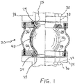
- FIG. 1 illustrates an elastomeric expansion joint 20 which is comprised of a fluid conductive flexible hollow body member 22 which may have a cylindrical or spherical shape with integral coupling elements 24, such as flanges, openings or other connectors, at each end adjacent openings 25 of the body member.
- Annular support members, such as coupling flanges 26, may be mounted on the opposite ends of the flexible body member 22 and held in place on the coupling elements 24.
- the coupling flanges 26 may be provided with a plurality of passages 28 suitable for receiving coupling bolts 30 which extend through passages 32 in flanges 34 of a piping system 36.
- the integral coupling elements 24 may have passages for receiving the coupling bolts 30. If the piping system 36 does not include flanges 34 at the open ends of the pipes, but instead uses different coupling elements, other coupling arrangements for the flexible body member 22 may be provided, as known in the art.
- the flexible body member 22 is formed of a natural or synthetic elastomer, such as neoprene rubber, butyl rubber, nitrile rubber, ethylene propylene diene monomer (EPDM) rubber, Viton rubber, silicone rubber, polyurethane rubber, Buna rubber, Teflon polymer, polyvinyl chloride rubber or natural rubber, among others, which may be combined with various reinforcing fibers, such as bias-ply tire cord.
- the flexible body member 22 may be formed by a built-up series of layers 36 ( FIG. 3 ) of elastomer material 36A, 36C and fiber material 36B, or the elastomer material and fiber material may be mixed together.
- the material, mixed or in layers, may be inserted into a mold and heat and pressure applied to cure the elastomeric material to form the body member 22.
- the particular materials used and the method of fabricating the body member 22 are selected to best meet the requirements of the particular mechanical and/or chemical conditions and the temperature and pressure conditions to which the flexible connector 20 is to be subjected.
- At least one stretchable sensor 40 is provided on or within the material of the body member 22 or on the exterior or interior surface of the material. If the material of the body member 22 is a mixture of elastomeric material and fibers, the sensor 40 may be merely positioned below the outer surface of the material before the molding process is completed, so that the sensor will be molded in place within the body member 22. If the material of the body member 22 is comprised of alternating layers 36 of elastomeric material and fibers, the sensor 40 may be inserted between any two layers of elastomeric material and fibers, such as below the outermost layer 36A of elastomeric material and above the outermost layer of fiber 36B, so that the sensor will be covered by an elastomeric layer when the molding process occurs.
- the senor 40 may be attached to the exterior or interior surface of the body member 22 such as by gluing or other attachment arrangements, such that the sensor will stretch and contract as the body member stretches and contracts. If the sensor 40 is being used in an application where the body member 22 is subject to wear or deterioration, such as in a pipeline for transporting abrasive or corrosive material, or in an environment where the body member is surrounded by a caustic gas or liquid, then at least one sensor 40 should be placed on interior surface of the body where it will be exposed to the abrasive or corrosive material.
- Each sensor 40 has two spaced apart electrodes 42 and an intervening element 44 ( Fig. 4 ).
- the element 44 is configured to provide a varying electrical characteristic when the sensor 40 is stretched and an electrical potential is applied to the electrodes 44.
- the electrical potential may be applied via a direct wired connection to the electrodes 42, or by means of the formation of an electrical field that encompasses the sensor 40. If the electrical potential is applied via a direct wired connection, there may be provided short leads that extend out of the outer layer 36A to be later connected to appropriate electrical connectors or wires.
- the senor 40 comprises as electroactive polymer (EAP) as the intervening element 44.
- EAP electroactive polymer
- the electrodes 42 and the intervening element 44 are resiliently stretchable, and stretch and contract as the material of the body member 22 stretches and contracts as the pressure of the fluid in the body member 22 changes.
- a particular sensor 40 of this type is presently produced by Parker Hannifin Corp.
- the analysis circuit 50 is connected to the electrodes 42.
- the analysis circuit 50 is configured to receive the varying electrical characteristic of the sensor 40 and to emit a signal corresponding to a level of the electrical characteristic received by the analysis circuit.
- This data may be collected and stored in a memory unit 51 to be accessed and/or analyzed at a later time.
- the data may be used to emit an alarm signal via an alarm device 52 when a predetermined characteristic level is being received by the analysis circuit.
- the analysis may be a part of a computer or computer system 53, or may be connected to a computer or computer system that may be programmed to analyze the data collected and to determine whether to emit an alarm signal.
- the alarm device 52 may be configured to provide either an audible alarm signal, such as the buzzing of a buzzer or blare of a horn, or a visual alarm signal such as the shining of a light.
- the alarm device 52 may also send a signal to another device 54, such as the computer or computer system 53, to terminate operation of any processes utilizing the piping system, or to provide a visible or audible signal at a computer terminal.
- the senor 40 has a length L which extends around at least a portion of a circumference C of the body member 22.
- the length L of the sensor may extend around a quarter of the circumference C of the body member 22, or the length L of the sensor could be lesser or greater, and the length of the sensor could extend around the full circumference of the body member 22. In this manner, the sensor 40 will provide a signal that can be interpreted to be a measurement of the increase in the circumference or diameter of the body member 22.
- multiple sensors 40 may be placed at different locations on the body member 22 that may be subject to different stretches and aging characteristics.
- One or more sensors 40 may be located along a greatest circumference of the body member 22, while one or more sensors 40 may be located in various areas that may be subject to various stresses, such as in the neck areas or near the coupling elements 24 of the body member.
- a sensor 40 may also be applied to the interior surface of the body member 22 to detect deterioration or wear due to the characteristics of the fluid flowing through the body.
- a sensor 40 may also be applied to the exterior surface of the body member 22 to detect deterioration or wear due to the characteristics of the atmosphere or liquid surrounding the body member.
- the body member 22 During normal operation of the body member 22, it will likely be subjected to the presence and/or flow of a pressurized fluid. Due to its elastomeric and resilient composition, the diameter and the circumference of the body member 22 will increase and/or decrease by a known or measurable amount during such normal operating conditions at the expected pressure and temperature of the fluid in the piping system 36.
- the integrity of the elastomeric material will begin to decline, causing the body member to expand to a greater degree at a given temperature and pressure of the fluid therein, or it may stiffen and fail to expand to a normal degree at a given temperature and pressure of the fluid.
- the sensor 40 and the analysis circuit 50 can detect this stretching and/or shrinking of the material of the body member 22. This information may be collected and analyzed to determine the status and/or condition of the body member 22. As mentioned above, multiple sensors 40 may be employed to provide information regarding the status of different portions of the body member 22.
- the electrical characteristic of the sensor will be affected by the wear or deterioration and the analysis circuit 50 will be able to detect this wear or deterioration, and its degree.
- the analysis circuit 50 can be configured to emit an alarm signal once the detected stretching, deterioration or wear of the material (as indicated by the varying electrical characteristic of the sensor 40) has reached a certain predetermined level.
- the circumference C of the body member 22 at a predetermined temperature and pressure expected for the placement of the elastomeric expansion joint 20 can be used as a base line measurement.
- the analysis circuit can be configured to emit an alarm signal once the varying electrical characteristic reaches a level that would indicate an increase in the circumference of the body member 22 of a predetermined amount, for example, 120%, of the baseline measurement.
- the particular increase over the base line measurement for initiation of the alarm signal can be determined for a particular expansion joint 20 depending on the size of the body member 22, the material and construction of the body member and other experience determined factors. Also, if multiple sensors 40 are employed, different levels for triggering an alarm signal may used for sensors located at different positions on the body member 22, and the levels sensed may indicate either a greater or lesser stretching, deterioration or wear of the body member than would be normal for a given pressure and temperature of the fluid in the body member.
- the invention thus provides for a method of pre-determining a failure condition of a hollow elastomeric body expansion joint 20 prior to an actual failure of the joint.
- Such a method would comprise the following steps: Providing a stretchable sensor 40 on or within a material of the hollow elastomeric body 22.
- the sensor element may have two spaced apart electrodes 42 and an intervening element 44.
- the element may be configured to provide a varying electrical characteristic when the sensor 40 is stretched, deteriorated or worn and an electrical potential is applied to the electrodes 42.
- Emitting a signal corresponding to a level of the electrical characteristic received by the analysis circuit Emitting a signal corresponding to a level of the electrical characteristic received by the analysis circuit.
Landscapes
- Engineering & Computer Science (AREA)
- General Engineering & Computer Science (AREA)
- Mechanical Engineering (AREA)
- Investigating Or Analyzing Materials By The Use Of Electric Means (AREA)
- Testing Of Devices, Machine Parts, Or Other Structures Thereof (AREA)
Abstract
An expansion joint (20) comprising a hollow elastomeric body (22) having coupling flanges (24) at each open end configured to connect to flanges of a pipe system. The hollow elastomeric body is comprised of a material comprising an elastomer. A stretchable sensor (40) is located within the material of the hollow elastomeric body. The sensor is configured to provide a varying electrical characteristic when the sensor is stretched, contracts and deteriorates or wears. An analysis circuit (50) is connected to the sensor, the analysis circuit configured to receive the varying electrical characteristic and to emit a signal corresponding to a level of the electrical characteristic received by the analysis circuit.
Description
- This application is a continuation-in-part application from
U.S. Application 14/551,868 - The present invention relates to an elastomeric expansion joint, and in particular, to a sensor for determining a pre-failure condition of the elastomeric expansion joint.
- Elastomer (rubber) expansion joints have been specified for many years to accommodate movement in piping runs and insure efficient systems. Elastomer joints are widely used to provide efficient ways to relieve movement stresses, reduce noise, isolate vibration, and compensate for misalignment.
- A particular type of elastomer expansion joint is disclosed in
U.S. Patent No. 5,273,321 , the disclosures of which are incorporated herein by reference. - Although elastomer expansion joints provide many advantages, over time the elastomeric material of the joint begins to weaken and stiffen or swell, eventually leading to failure of the joint by bursting of the joint.
- Although joints could be proactively replaced in advance of failure based on a time-in-service measurement, oftentimes such a measurement results in premature replacement of the joint, at a substantial expense, not just for a new joint and the labor cost to make the replacement, but also due to down time for the piping system that the joint is a part of.
- It would be an improvement in the art if there were provided a mechanism for determining an approaching failure condition of the expansion joint, sufficiently in advance of the failure time to allow for routine replacement of the joint, but not so far in advance as to be a premature replacement of a usable joint.
- The present invention provides a mechanism for providing information about and determining an approaching failure condition of the expansion joint, sufficiently in advance of the failure time to allow for routine replacement of the joint, but not so far in advance as to be a premature replacement of a usable joint.
- In an embodiment of the invention, there is provided an expansion joint comprising a hollow elastomeric body having coupling elements at each open end configured to connect to coupling elements of a pipe system. The hollow elastomeric body may be comprised of a material comprising an elastomer and perhaps strengthening fibers. A stretchable sensor is positioned within the material of the hollow body or attached to the interior or exterior of the hollow body. The sensor element has two spaced apart electrodes and an intervening element, the element configured to provide a varying electrical characteristic when the sensor stretches or contracts and an electrical potential is applied to the electrodes. The sensor element will also provide a varying electrical characteristic if the sensor is deteriorated by the fluid flowing through the hollow body, such as an abrasive slurry which may physically wear away portions of the sensor. An analysis circuit is connected to the electrodes, the analysis circuit configured to receive the varying electrical characteristic and to emit a signal corresponding to a level of the electrical characteristic received by the analysis circuit. This data may be collected and accessed and/or analyzed at a later time, or the data may be used to emit an alarm signal when a predetermined characteristic level is being received by the analysis circuit.
- In an embodiment, the hollow elastomeric body is comprised of a plurality of alternating elastomeric and fiber layers superimposed one over the other and joined via a molding process at an elevated temperature and pressure. The sensor element may be positioned between any of the elastomer layers and fiber layers and, for example, may be positioned between an outermost elastomer layer and an outermost fiber layer.
- The alarm signal may be at least one of an audible and a visible signal.
- The analysis circuit may be configured to emit an alarm signal when the sensor the varying characteristic indicates that the elastomeric body has expanded to a predetermined circumference larger than an original circumference of the normal operating conditions for the expansion joint, indicating a weakening of the elastomeric material, or failing to expand to a predetermined degree upon the application of an increased pressure inside the elastomeric body, indicating a stiffening of the elastomeric material.
- The invention may also comprise a method of pre-determining an approaching failure condition of a hollow elastomeric body expansion joint comprising the steps:
- providing a stretchable sensor element on or within a material of the hollow elastomeric body, the sensor element having two spaced apart electrodes and an intervening element, the sensor element configured to provide a varying electrical characteristic when the sensor stretches and contracts, or is physically eroded or deteriorated, and an electrical potential is applied to the electrodes,
- applying an electrical potential to the electrodes,
- measuring a level of the electrical characteristic of the sensor element, and
- emitting a signal corresponding to a level of the electrical characteristic received by the analysis circuit.
- The features of the present invention which are believed to be novel, are set forth with particularity in the appended claims. The invention, together with further objects and advantages, may best be understood by reference to the following description taken in conjunction with the accompanying drawings, in the several figures in which like reference numerals identify like elements, and in which:
-
FIG. 1 is a side sectional and schematic view of an elastomeric expansion joint and associated circuitry embodying the principles of the present invention. -
FIG. 2 is a side sectional and schematic view of a second embodiment of an elastomeric expansion joint and associated circuitry embodying the principles of the present invention. -
FIG. 3 is a partial sectional view of the elastomeric body with multiple sensors positioned between the layers of the material of the body. -
FIG. 4 is a perspective view of an embodiment of the sensor in isolation. -
FIG. 5 is a schematic view of the sensor, analysis circuit and associated devices. -
FIG. 6 is a sectional view through the elastomeric body showing the circumferential extent of the sensor in an embodiment of the invention. -
FIG. 1 illustrates anelastomeric expansion joint 20 which is comprised of a fluid conductive flexiblehollow body member 22 which may have a cylindrical or spherical shape withintegral coupling elements 24, such as flanges, openings or other connectors, at each endadjacent openings 25 of the body member. Annular support members, such ascoupling flanges 26, may be mounted on the opposite ends of theflexible body member 22 and held in place on thecoupling elements 24. Thecoupling flanges 26 may be provided with a plurality ofpassages 28 suitable for receivingcoupling bolts 30 which extend throughpassages 32 inflanges 34 of apiping system 36. Alternatively, theintegral coupling elements 24 may have passages for receiving thecoupling bolts 30. If thepiping system 36 does not includeflanges 34 at the open ends of the pipes, but instead uses different coupling elements, other coupling arrangements for theflexible body member 22 may be provided, as known in the art. - The
flexible body member 22 is formed of a natural or synthetic elastomer, such as neoprene rubber, butyl rubber, nitrile rubber, ethylene propylene diene monomer (EPDM) rubber, Viton rubber, silicone rubber, polyurethane rubber, Buna rubber, Teflon polymer, polyvinyl chloride rubber or natural rubber, among others, which may be combined with various reinforcing fibers, such as bias-ply tire cord. In a particular embodiment, theflexible body member 22 may be formed by a built-up series of layers 36 (FIG. 3 ) ofelastomer material fiber material 36B, or the elastomer material and fiber material may be mixed together. The material, mixed or in layers, may be inserted into a mold and heat and pressure applied to cure the elastomeric material to form thebody member 22. The particular materials used and the method of fabricating thebody member 22 are selected to best meet the requirements of the particular mechanical and/or chemical conditions and the temperature and pressure conditions to which theflexible connector 20 is to be subjected. - At least one
stretchable sensor 40 is provided on or within the material of thebody member 22 or on the exterior or interior surface of the material. If the material of thebody member 22 is a mixture of elastomeric material and fibers, thesensor 40 may be merely positioned below the outer surface of the material before the molding process is completed, so that the sensor will be molded in place within thebody member 22. If the material of thebody member 22 is comprised ofalternating layers 36 of elastomeric material and fibers, thesensor 40 may be inserted between any two layers of elastomeric material and fibers, such as below theoutermost layer 36A of elastomeric material and above the outermost layer offiber 36B, so that the sensor will be covered by an elastomeric layer when the molding process occurs. Alternatively, thesensor 40 may be attached to the exterior or interior surface of thebody member 22 such as by gluing or other attachment arrangements, such that the sensor will stretch and contract as the body member stretches and contracts. If thesensor 40 is being used in an application where thebody member 22 is subject to wear or deterioration, such as in a pipeline for transporting abrasive or corrosive material, or in an environment where the body member is surrounded by a caustic gas or liquid, then at least onesensor 40 should be placed on interior surface of the body where it will be exposed to the abrasive or corrosive material. As the material flows through thebody member 22, it will deteriorate thesensor 40 more quickly than the body member and will cause thesensor 40 to provide a varying electrical characteristic outside of the normal range, which can then be detected by an analysis circuit described below to indicate that the body member should be replace, before actual failure of thebody member 22 occurs. - Each
sensor 40 has two spaced apartelectrodes 42 and an intervening element 44 (Fig. 4 ). Theelement 44 is configured to provide a varying electrical characteristic when thesensor 40 is stretched and an electrical potential is applied to theelectrodes 44. The electrical potential may be applied via a direct wired connection to theelectrodes 42, or by means of the formation of an electrical field that encompasses thesensor 40. If the electrical potential is applied via a direct wired connection, there may be provided short leads that extend out of theouter layer 36A to be later connected to appropriate electrical connectors or wires. - In an embodiment, the
sensor 40 comprises as electroactive polymer (EAP) as theintervening element 44. Theelectrodes 42 and the interveningelement 44 are resiliently stretchable, and stretch and contract as the material of thebody member 22 stretches and contracts as the pressure of the fluid in thebody member 22 changes. - As the
sensor 40 stretches (contracts) along with thebody member 22, its area increases (decreases) and an electrical characteristic, such as its capacitance, changes, such as by increasing (decreasing). Aparticular sensor 40 of this type is presently produced by Parker Hannifin Corp. - As shown in
FIG. 5 , theanalysis circuit 50 is connected to theelectrodes 42. Theanalysis circuit 50 is configured to receive the varying electrical characteristic of thesensor 40 and to emit a signal corresponding to a level of the electrical characteristic received by the analysis circuit. This data may be collected and stored in amemory unit 51 to be accessed and/or analyzed at a later time. The data may be used to emit an alarm signal via analarm device 52 when a predetermined characteristic level is being received by the analysis circuit. The analysis may be a part of a computer orcomputer system 53, or may be connected to a computer or computer system that may be programmed to analyze the data collected and to determine whether to emit an alarm signal. - The
alarm device 52 may be configured to provide either an audible alarm signal, such as the buzzing of a buzzer or blare of a horn, or a visual alarm signal such as the shining of a light. Thealarm device 52 may also send a signal to anotherdevice 54, such as the computer orcomputer system 53, to terminate operation of any processes utilizing the piping system, or to provide a visible or audible signal at a computer terminal. - As shown in
FIG. 6 , thesensor 40 has a length L which extends around at least a portion of a circumference C of thebody member 22. For example, the length L of the sensor may extend around a quarter of the circumference C of thebody member 22, or the length L of the sensor could be lesser or greater, and the length of the sensor could extend around the full circumference of thebody member 22. In this manner, thesensor 40 will provide a signal that can be interpreted to be a measurement of the increase in the circumference or diameter of thebody member 22. - Further,
multiple sensors 40 may be placed at different locations on thebody member 22 that may be subject to different stretches and aging characteristics. One ormore sensors 40 may be located along a greatest circumference of thebody member 22, while one ormore sensors 40 may be located in various areas that may be subject to various stresses, such as in the neck areas or near thecoupling elements 24 of the body member. Asensor 40 may also be applied to the interior surface of thebody member 22 to detect deterioration or wear due to the characteristics of the fluid flowing through the body. Asensor 40 may also be applied to the exterior surface of thebody member 22 to detect deterioration or wear due to the characteristics of the atmosphere or liquid surrounding the body member. - During normal operation of the
body member 22, it will likely be subjected to the presence and/or flow of a pressurized fluid. Due to its elastomeric and resilient composition, the diameter and the circumference of thebody member 22 will increase and/or decrease by a known or measurable amount during such normal operating conditions at the expected pressure and temperature of the fluid in thepiping system 36. - However, as the
body member 22 ages, and after a significant length of time, and depending in part on the conditions that the body member is exposed to, the integrity of the elastomeric material will begin to decline, causing the body member to expand to a greater degree at a given temperature and pressure of the fluid therein, or it may stiffen and fail to expand to a normal degree at a given temperature and pressure of the fluid. Thesensor 40 and theanalysis circuit 50 can detect this stretching and/or shrinking of the material of thebody member 22. This information may be collected and analyzed to determine the status and/or condition of thebody member 22. As mentioned above,multiple sensors 40 may be employed to provide information regarding the status of different portions of thebody member 22. - Additionally, if the
sensor 40 is placed on the interior or exterior surface of thebody member 22 to detect wear or deterioration, the electrical characteristic of the sensor will be affected by the wear or deterioration and theanalysis circuit 50 will be able to detect this wear or deterioration, and its degree. - Also, for example, the
analysis circuit 50 can be configured to emit an alarm signal once the detected stretching, deterioration or wear of the material (as indicated by the varying electrical characteristic of the sensor 40) has reached a certain predetermined level. For example, the circumference C of thebody member 22 at a predetermined temperature and pressure expected for the placement of theelastomeric expansion joint 20 can be used as a base line measurement. The analysis circuit can be configured to emit an alarm signal once the varying electrical characteristic reaches a level that would indicate an increase in the circumference of thebody member 22 of a predetermined amount, for example, 120%, of the baseline measurement. The particular increase over the base line measurement for initiation of the alarm signal can be determined for aparticular expansion joint 20 depending on the size of thebody member 22, the material and construction of the body member and other experience determined factors. Also, ifmultiple sensors 40 are employed, different levels for triggering an alarm signal may used for sensors located at different positions on thebody member 22, and the levels sensed may indicate either a greater or lesser stretching, deterioration or wear of the body member than would be normal for a given pressure and temperature of the fluid in the body member. - The invention thus provides for a method of pre-determining a failure condition of a hollow elastomeric
body expansion joint 20 prior to an actual failure of the joint. Such a method would comprise the following steps:
Providing astretchable sensor 40 on or within a material of the hollowelastomeric body 22. The sensor element may have two spaced apartelectrodes 42 and an interveningelement 44. The element may be configured to provide a varying electrical characteristic when thesensor 40 is stretched, deteriorated or worn and an electrical potential is applied to theelectrodes 42. - Applying an electrical potential to the
electrodes 42. - Measuring a level of the electrical characteristic of the
sensor 40. - Emitting a signal corresponding to a level of the electrical characteristic received by the analysis circuit.
- As is apparent from the foregoing specification, the invention is susceptible of being embodied with various alterations and modifications which may differ particularly from those that have been described in the preceding specification and description. It should be understood that I wish to embody within the scope of the patent warranted hereon all such modifications as reasonably and properly come within the scope of my contribution to the art.
Claims (15)
- An expansion joint comprising:a fluid conductive hollow elastomeric body having coupling elements in the form of flanges at each open end configured to connect with flanges at open ends of pipes of a pipe system,
the hollow elastomeric body being comprised of a material comprising an elastomer,at least one stretchable sensor located on a surface of the hollow elastomeric body,
the sensor having two spaced apart electrodes and an intervening element, the element configured to provide a varying electrical characteristic when the sensor is stretched, contracted, and deteriorated or worn, and an electrical potential is applied to the electrodes, andan analysis circuit connected to the electrodes, the analysis circuit configured to receive the varying electrical characteristic and to emit a signal corresponding to a level of the electrical characteristic received by the analysis circuit. - The expansion joint of claim 1, wherein the elastomer of the hollow body comprises at least one of neoprene rubber, butyl rubber, nitrile rubber, ethylene propylene diene monomer (EPDM) rubber, Viton rubber, silicone rubber, polyurethane rubber, Buna rubber, Teflon polymer, polyvinyl chloride rubber and natural rubber.
- The expansion joint of claim 1, wherein the coupling elements are integrally formed with the hollow elastomeric body.
- The expansion joint of claim 1, wherein a plurality of sensors are located on or within the material of the hollow elastomeric body.
- The expansion joint of claim 1, wherein the sensor element comprises an electroactive polymer.
- The expansion joint of claim 1, wherein the varying electrical characteristic comprises an electrical capacitance of the sensor.
- The expansion joint of claim 6, wherein the capacitance changes as the sensor stretches, contracts and deteriorates or is worn.
- The expansion joint of claim 1, wherein the signal comprises at least one of an audible and a visible signal.
- The expansion joint of claim 1, wherein the sensor comprises a length extending along at least one quarter of a circumference of the hollow elastomeric body.
- The expansion joint of claim 1, wherein the analysis circuit is configured to emit an alarm signal when the varying characteristic indicates that the elastomeric body has expanded to a predetermined circumference larger than an original circumference of the normal operating conditions for the expansion joint.
- The expansion joint of claim 1, wherein the analysis circuit is configured to emit an alarm signal when the varying characteristic indicates that the sensor has deteriorated or been worn to a predetermined degree greater than an original condition of the sensor.
- The expansion joint of claim 1, wherein the sensor is located on an interior surface of the hollow elastomeric body.
- The expansion joint of claim 1, wherein the sensor is located on an exterior surface of the hollow elastomeric body.
- A method of pre-determining a failure condition of a hollow elastomeric body expansion joint comprising the steps:providing a stretchable sensor element on a material of the hollow elastomeric body, the element configured to provide a varying electrical characteristic when the sensor is stretched, contracted and deteriorated or worn and an electrical potential is applied to the electrodes,applying an electrical potential to the electrodes,measuring a level of the electrical characteristic of the sensor element, andemitting a signal corresponding to a level of the electrical characteristic received by the analysis circuit.
- The method of claim 14, wherein an alarm signal is emitted by the analysis circuit when the varying characteristic level indicates that at least a portion of the elastomeric body has expanded to a greater or lesser degree than would be expected under normal operating conditions for the expansion joint, and/or
wherein an alarm signal is emitted by the analysis circuit when the varying characteristic level indicates that the sensor has deteriorated or been worn to a predetermined degree greater than an original condition of the sensor.
Applications Claiming Priority (1)
| Application Number | Priority Date | Filing Date | Title |
|---|---|---|---|
| US16/111,654 US20180364130A1 (en) | 2014-11-24 | 2018-08-24 | Elastomeric expansion joint pre-failure sensor and method |
Publications (1)
| Publication Number | Publication Date |
|---|---|
| EP3614031A1 true EP3614031A1 (en) | 2020-02-26 |
Family
ID=67551255
Family Applications (1)
| Application Number | Title | Priority Date | Filing Date |
|---|---|---|---|
| EP19190459.8A Withdrawn EP3614031A1 (en) | 2018-08-24 | 2019-08-07 | Elastomeric expansion joint pre-failure sensor and method |
Country Status (2)
| Country | Link |
|---|---|
| EP (1) | EP3614031A1 (en) |
| JP (1) | JP2020030209A (en) |
Families Citing this family (1)
| Publication number | Priority date | Publication date | Assignee | Title |
|---|---|---|---|---|
| JP7607989B1 (en) | 2024-01-05 | 2025-01-06 | 株式会社エーアンドエーマテリアル | Expansion joints |
Citations (3)
| Publication number | Priority date | Publication date | Assignee | Title |
|---|---|---|---|---|
| US5273321A (en) | 1992-05-26 | 1993-12-28 | Richter James R | Flexible connector with integral flexible extension controls |
| US20160146394A1 (en) * | 2014-11-24 | 2016-05-26 | The Metraflex Company | Elastomeric expansion joint pre-failure sensor and method |
| US20170009550A1 (en) * | 2014-01-24 | 2017-01-12 | Managed Pressure Operations Pte. Ltd. | Sealing element wear indicator system |
-
2019
- 2019-08-07 EP EP19190459.8A patent/EP3614031A1/en not_active Withdrawn
- 2019-08-15 JP JP2019149025A patent/JP2020030209A/en active Pending
Patent Citations (3)
| Publication number | Priority date | Publication date | Assignee | Title |
|---|---|---|---|---|
| US5273321A (en) | 1992-05-26 | 1993-12-28 | Richter James R | Flexible connector with integral flexible extension controls |
| US20170009550A1 (en) * | 2014-01-24 | 2017-01-12 | Managed Pressure Operations Pte. Ltd. | Sealing element wear indicator system |
| US20160146394A1 (en) * | 2014-11-24 | 2016-05-26 | The Metraflex Company | Elastomeric expansion joint pre-failure sensor and method |
Also Published As
| Publication number | Publication date |
|---|---|
| JP2020030209A (en) | 2020-02-27 |
Similar Documents
| Publication | Publication Date | Title |
|---|---|---|
| US10247335B2 (en) | Elastomeric expansion joint pre-failure sensor and method | |
| EP2867642B1 (en) | Abrasion monitoring system for hose assembly | |
| US9562822B2 (en) | Flexible contact arrangement for hose assembly | |
| KR101604153B1 (en) | Hose with fault detection capability | |
| AU2011253076B2 (en) | Sensor sleeve for health monitoring an article | |
| US7752904B2 (en) | Structures with integral life-sensing capability | |
| US20150240972A1 (en) | Wave contact arrangement for hose assembly | |
| US10309864B1 (en) | Exterior tubing monitoring devices | |
| US5518034A (en) | Flexible hose with a visibly deformable structure upon an internal failure within the hose | |
| HU218649B (en) | Floatable flexible hose | |
| CN108603621B (en) | Condition monitoring system for marine hoses | |
| US7959155B2 (en) | Packer cup | |
| EP3303897A1 (en) | Flexible pipe joint having an annular flexible boot thermally or chemically insulating an annular elastomeric flexible element | |
| BR112017008692B1 (en) | Apparatus for determining a bending radius of a flexible tube and method for monitoring bending of a flexible tube | |
| US20180364130A1 (en) | Elastomeric expansion joint pre-failure sensor and method | |
| JP2020030209A (en) | Elastomeric expansion joint pre-failure sensor and method | |
| CN105229256B (en) | For providing Fresh fats element to flexible pipe and removing the method and apparatus of existing fibre element | |
| GB2374647A (en) | Hose deterioration measuring method | |
| KR20240051738A (en) | Pneumatic pipe plug for repairing water and wastewater pipe | |
| GB2368378A (en) | Hose and deterioration measuring method of same | |
| JP2010071344A (en) | Flexible pipe joint | |
| BR112020019317A2 (en) | FLEXIBLE TUBE BODY AND METHOD | |
| JP2009068536A (en) | Marine hose |
Legal Events
| Date | Code | Title | Description |
|---|---|---|---|
| PUAI | Public reference made under article 153(3) epc to a published international application that has entered the european phase |
Free format text: ORIGINAL CODE: 0009012 |
|
| STAA | Information on the status of an ep patent application or granted ep patent |
Free format text: STATUS: THE APPLICATION HAS BEEN PUBLISHED |
|
| AK | Designated contracting states |
Kind code of ref document: A1 Designated state(s): AL AT BE BG CH CY CZ DE DK EE ES FI FR GB GR HR HU IE IS IT LI LT LU LV MC MK MT NL NO PL PT RO RS SE SI SK SM TR |
|
| AX | Request for extension of the european patent |
Extension state: BA ME |
|
| STAA | Information on the status of an ep patent application or granted ep patent |
Free format text: STATUS: THE APPLICATION IS DEEMED TO BE WITHDRAWN |
|
| 18D | Application deemed to be withdrawn |
Effective date: 20200827 |