EP3614063A1 - Unité intérieure pour climatiseur - Google Patents
Unité intérieure pour climatiseur Download PDFInfo
- Publication number
- EP3614063A1 EP3614063A1 EP18805303.7A EP18805303A EP3614063A1 EP 3614063 A1 EP3614063 A1 EP 3614063A1 EP 18805303 A EP18805303 A EP 18805303A EP 3614063 A1 EP3614063 A1 EP 3614063A1
- Authority
- EP
- European Patent Office
- Prior art keywords
- indoor unit
- heat exchange
- exchange part
- partition
- heat exchanger
- Prior art date
- Legal status (The legal status is an assumption and is not a legal conclusion. Google has not performed a legal analysis and makes no representation as to the accuracy of the status listed.)
- Granted
Links
Images





Classifications
-
- F—MECHANICAL ENGINEERING; LIGHTING; HEATING; WEAPONS; BLASTING
- F24—HEATING; RANGES; VENTILATING
- F24F—AIR-CONDITIONING; AIR-HUMIDIFICATION; VENTILATION; USE OF AIR CURRENTS FOR SCREENING
- F24F13/00—Details common to, or for air-conditioning, air-humidification, ventilation or use of air currents for screening
- F24F13/24—Means for preventing or suppressing noise
-
- F—MECHANICAL ENGINEERING; LIGHTING; HEATING; WEAPONS; BLASTING
- F24—HEATING; RANGES; VENTILATING
- F24F—AIR-CONDITIONING; AIR-HUMIDIFICATION; VENTILATION; USE OF AIR CURRENTS FOR SCREENING
- F24F1/00—Room units for air-conditioning, e.g. separate or self-contained units or units receiving primary air from a central station
- F24F1/0007—Indoor units, e.g. fan coil units
- F24F1/0043—Indoor units, e.g. fan coil units characterised by mounting arrangements
- F24F1/0047—Indoor units, e.g. fan coil units characterised by mounting arrangements mounted in the ceiling or at the ceiling
-
- F—MECHANICAL ENGINEERING; LIGHTING; HEATING; WEAPONS; BLASTING
- F24—HEATING; RANGES; VENTILATING
- F24F—AIR-CONDITIONING; AIR-HUMIDIFICATION; VENTILATION; USE OF AIR CURRENTS FOR SCREENING
- F24F1/00—Room units for air-conditioning, e.g. separate or self-contained units or units receiving primary air from a central station
- F24F1/0007—Indoor units, e.g. fan coil units
- F24F1/0059—Indoor units, e.g. fan coil units characterised by heat exchangers
- F24F1/0063—Indoor units, e.g. fan coil units characterised by heat exchangers by the mounting or arrangement of the heat exchangers
-
- F—MECHANICAL ENGINEERING; LIGHTING; HEATING; WEAPONS; BLASTING
- F24—HEATING; RANGES; VENTILATING
- F24F—AIR-CONDITIONING; AIR-HUMIDIFICATION; VENTILATION; USE OF AIR CURRENTS FOR SCREENING
- F24F1/00—Room units for air-conditioning, e.g. separate or self-contained units or units receiving primary air from a central station
- F24F1/0007—Indoor units, e.g. fan coil units
- F24F1/0059—Indoor units, e.g. fan coil units characterised by heat exchangers
- F24F1/0067—Indoor units, e.g. fan coil units characterised by heat exchangers by the shape of the heat exchangers or of parts thereof, e.g. of their fins
-
- F—MECHANICAL ENGINEERING; LIGHTING; HEATING; WEAPONS; BLASTING
- F24—HEATING; RANGES; VENTILATING
- F24F—AIR-CONDITIONING; AIR-HUMIDIFICATION; VENTILATION; USE OF AIR CURRENTS FOR SCREENING
- F24F13/00—Details common to, or for air-conditioning, air-humidification, ventilation or use of air currents for screening
- F24F13/30—Arrangement or mounting of heat-exchangers
Definitions
- the present invention relates to an indoor unit for an air conditioner.
- a conventional indoor unit for an air conditioner includes a heat exchanger having a U shape, a partition with which an opening of the heat exchanger is covered, and a turbo fan surrounded with the heat exchanger and the partition and configured to suck in and blow out air in two directions via the heat exchanger (see, for example, JP 2015-81692 A (Patent Literature 1).
- the partition has a protrusion extending toward the turbo fan, and the protrusion equalizes airflows directed to blow-out ports in the two directions.
- Patent Literature 1 JP 2015-81692 A
- the turbo fan has a center located on a center line of the heat exchanger and a center line of a casing main body, and each of the heat exchanger and the partition has a laterally symmetrical shape. Accordingly, the left airflow and the right airflow are different from each other although the turbo fan rotates in a single direction. Consequently, a high-pressure spot occurs at the partition, which makes unusual noise.
- the present invention sets out to provide an indoor unit for an air conditioner, the indoor unit being capable of reducing a pressure at a high-pressure spot that occurs at an end of a partition with which an opening of a heat exchanger is covered, to thereby reduce unusual noise.
- An aspect of the present invention provides an indoor unit for an air conditioner, including:
- the center of the centrifugal fan configured to rotate in the predetermined rotation direction is located upstream of the current of air between the centrifugal fan and the partition, with respect to the perpendicular bisector of the line connecting the two ends of the partition. Consequently, a clearance between an outer periphery of the centrifugal fan and the downstream-side end of the partition with which an opening of the heat exchanger is covered is larger than a clearance between the outer periphery of the centrifugal fan and the upstream-side end of the partition.
- This configuration therefore enables reduction in pressure near the downstream-side end of the partition that makes loud unusual noise.
- This configuration thus enables reduction in pressure at a high-pressure spot that occurs at the end of the partition with which the opening of the heat exchanger is covered, to thereby reduce unusual noise.
- the casing has a blow-out port at a position opposite to the partition with respect to the heat exchanger.
- the casing has the blow-out port at the position opposite to the partition with respect to the heat exchanger. Therefore, air from the centrifugal fan is smoothly blown out through the blow-out port via the heat exchanger.
- the partition is bowed outward beyond the line connecting the two ends in plan view, and the centrifugal fan partially overlaps a region surrounded with the partition and the line connecting the two ends of the partition.
- the partition is bowed outward beyond the line connecting the two ends of the partition in plan view.
- the centrifugal fan partially overlaps the region surrounded with the partition and the line connecting the two ends of the partition. Therefore, the centrifugal fan rotates along the partition bowed outward, and the partition smoothly guides air from the centrifugal fan, which contributes to reduction in space for housing the components in the casing.
- the heat exchanger includes:
- the third heat exchange part located at the downstream side of the first heat exchange part with respect to the rotation direction of the centrifugal fan is shorter in length than the second heat exchange part located at the upstream side of the first heat exchange part with respect to the rotation direction of the centrifugal fan. Therefore, pipe connection parts may be connected to an end of the third heat exchange part. In other words, a space for connecting pipes is ensured in the casing.
- the clearance between the outer periphery of the centrifugal fan and the downstream-side end of the partition is made larger than the clearance between the outer periphery of the centrifugal fan and the upstream-side end of the partition.
- an indoor unit for an air conditioner is arranged such that a centrifugal fan configured to rotate in a predetermined rotation direction is disposed with a center thereof located upstream of a current of air between the centrifugal fan and a partition, with respect to a perpendicular bisector of a line connecting two ends of the partition, whereby it is possible to reduce a pressure at a high-pressure spot that may occur at an end of the partition with which an opening of a heat exchanger is covered, to thereby reduce unusual noise.
- FIG. 1 is a perspective view of an indoor unit for an air conditioner according to a first embodiment of the present invention, the indoor unit being seen obliquely from below. This indoor unit is designed to be embedded in a ceiling.
- the indoor unit for an air conditioner includes a casing main body 1, a panel 2 having a rectangular shape, the panel 2 being mounted to a lower side of the casing main body 1, and a grille 3 detachably mounted to the panel 2.
- the casing main body 1, the panel 2, and the grille 3 constitute a casing.
- the panel 2 has, in its longitudinal end, a blow-out port 10 extending along a shorter edge of the panel 2.
- the panel 2 also has a flap 20 pivotably mounted thereto. In FIG. 1 , the flap 20 closes the blow-out port 10.
- the indoor unit also includes a drain socket 7 protruding from a sidewall of the casing main body 1.
- the drain socket 7 is connected to an external drain hose (not illustrated).
- the indoor unit also includes pipe connection parts 5 and 6 each protruding from the sidewall of the casing main body 1. Each of the pipe connection parts 5 and 6 is connected to an external refrigerant pipe (not illustrated).
- the indoor unit also includes an electrical component unit 8 and hanger fittings 101 to 103 each protruding sideward from the casing main body 1.
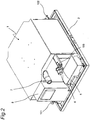
- FIG. 2 is a perspective view of the indoor unit seen obliquely from above.
- the same constituent elements as those illustrated in FIG. 1 are denoted with the same reference signs.
- FIG. 3 is a bottom view of the indoor unit.
- the same constituent elements as those illustrated in FIG. 1 are denoted with the same reference signs.
- the casing main body 1 has in its center a suction port 1a.
- a filter 4 (see FIG. 4 ) is attached between the suction port 1a and the grille 3.
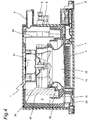
- FIG. 4 is a sectional view taken along line IV-IV in FIG. 3 .
- the same constituent elements as those illustrated in FIGS. 1 to 3 are denoted with the same reference signs.
- the casing main body 1 houses therein a turbo fan 30 to be driven by a motor 31.
- the casing main body 1 also houses therein a bell mouth 32 at a position between the suction port 1a and the turbo fan 30.
- the casing main body 1 also houses therein a heat exchanger 40 and a partition plate 50 at a position around the turbo fan 30.
- the casing main body 1 also houses therein a drain pan 60 at a position below the heat exchanger 40 and the partition plate 50.
- the turbo fan 30 is an example of a centrifugal fan.
- the partition plate 50 is an example of a partition. The partition may be integrated with the casing.
- An air flow path P is provided within the casing main body 1 for guiding air from the turbo fan 30 to the blow-out port 10 in the panel 2.
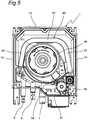
- FIG. 5 is a bottom view of the indoor unit from which the panel 2, the drain pan 60, and the like are detached.
- the casing main body 1 includes a first wall 11 located near the blow-out port 10 (see FIG. 9 ), a second wall 12 opposite to the first wall 11, a third wall 13 connecting the first wall 11 and the second wall 12, and a fourth wall 14 connecting the first wall 11 and the second wall 12 and opposite to the third wall 13.
- the heat exchanger 40 includes a first heat exchange part 41, a second heat exchange part 42 located at an upstream side of the first heat exchange part 41 with respect to a rotation direction (arrow R1) of the turbo fan 30 in plan view, and a third heat exchange part 43 located at a downstream side of the first heat exchange part 41 with respect to the rotation direction (arrow R1) of the turbo fan 30 in plan view.
- the heat exchanger 40 has two ends connected to the partition plate 50 having an arcuate shape, so that the turbo fan 30 is surrounded with the heat exchanger 40 and the partition plate 50.
- the partition plate 50 is bowed outward.
- the pipe connection parts 5 and 6 are connected to an end of the third heat exchange part 43 of the heat exchanger 40.
- the casing main body 1 also houses therein a drain pump 70 at a position between the partition plate 50 and the second wall 12 and near the third wall 13.
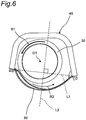
- FIG. 6 illustrates a center O1 of the turbo fan 30 in the indoor unit.
- the center O1 of the turbo fan 30 is located upstream of a current of air (indicated by an arrow R2) between the turbo fan 30 and the partition plate 50, with respect to a perpendicular bisector L2 of a line L1 connecting the two ends of the partition plate 50.
- the center O1 of the turbo fan 30 is located on the left side of the perpendicular bisector L2 in FIG. 6 .
- the position of the center O1 of the turbo fan 30 is set as illustrated in FIG. 7 .
- the heat exchanger 40 includes a heat exchange part 40a (a hatched region in FIG. 7 ) having a line symmetrical shape in plan view.
- the turbo fan 30 is disposed such that the center O1 of the turbo fan 30 is located upstream of the current of air (indicated by the arrow R2) between the turbo fan 30 and the partition plate 50, with respect to a symmetry axis L3 of the heat exchange part 40a having the line symmetrical shape.
- the turbo fan 30 is disposed such that the center O1 of the turbo fan 30 is located on the left side of the symmetry axis L3 in FIG. 7 .
- the heat exchanger 40 is disposed in the casing main body 1 such that the symmetry axis L3 of the heat exchange part 40a having the line symmetrical shape in the heat exchanger 40 is aligned with a longitudinal center line of the casing main body 1.
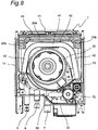
- FIG. 8 illustrates the indoor unit which is illustrated in FIG. 5 and to which the flap 20 (diagonally shaded) is attached.
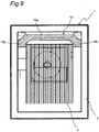
- FIG. 9 illustrates the indoor unit from which the flap 20 is detached.
- the same constituent elements as those illustrated in FIGS. 1 to 7 are denoted with the same reference signs.
- the heat exchanger 40 having a U shape in plan view includes the first heat exchange part 41 extending in parallel with the first wall 11 of the casing main body 1, the second heat exchange part 42 seamlessly elongated from a first end of the first heat exchange part 41, and the third heat exchange part 43 seamlessly elongated from a second end of the first heat exchange part 41.
- a clearance between the second heat exchange part 42 and the third wall 13 is tapered from the first heat exchange part 41 toward a distal end, or tip, of the second heat exchange part 42.
- a clearance between the third heat exchange part 43 and the fourth wall 14 is tapered from the first heat exchange part 41 toward a distal end, or tip, of the third heat exchange part 43.
- a distance between the second heat exchange part 42 and the third heat exchange part 43 gradually increases toward the two ends of the heat exchanger 40.
- the blow-out port 10 includes a first blow-out port part 10a having a rectangular shape and extending along the first wall 11 (see FIG. 8 ) of the casing main body 1, and second blow-out port parts 10b respectively elongated from two ends of the first blow-out port part 10a toward the second wall 12 (see FIG. 8 ) of the casing main body 1.
- the flap 20 configured to control a direction of air to be blown out through the blow-out port 10 includes a flap main body 20a extending along the first wall 11 of the casing main body 1, and auxiliary flaps 20b respectively elongated from two ends of the flap main body 20a toward the second wall 12 of the casing main body 1.
- the center O1 of the turbo fan 30 (centrifugal fan) configured to rotate in the predetermined rotation direction (R1) is located upstream of the current of air (R2) between the turbo fan 30 and the partition plate 50, with respect to the perpendicular bisector L2 of the line L1 connecting the two ends of the partition plate 50 (partition). Consequently, a clearance between an outer periphery of the turbo fan 30 and the downstream-side end of the partition plate 50 with which the opening of the heat exchanger 40 is covered is larger than a clearance between the outer periphery of the turbo fan 30 and the upstream-side end of the partition plate 50.
- This configuration therefore enables reduction in pressure near the downstream-side end of the partition plate 50 that makes loud unusual noise.
- This configuration thus enables reduction in pressure at a high-pressure spot that may occur at the end of the partition plate 50 with which the opening of the heat exchanger 40 is covered, to thereby reduce unusual noise.
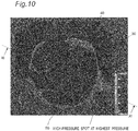
- the inventors of the present invention performed a simulation on the condition that the center O1 of the turbo fan 30 is located upstream of the current of air (R2) between the turbo fan 30 and the partition plate 50, with respect to the perpendicular bisector L2 of the line L1 connecting the two ends of the partition plate 50. It was confirmed by this simulation that the indoor unit having the configuration described above reduces a pressure near the downstream-side end of the partition plate 50, and therefore reduces a pressure at a high-pressure spot that occurs at the end of the partition plate 50 with which the opening of the heat exchanger 40 is covered, to thereby reduce unusual noise.
- FIG. 10 illustrates a pressure distribution obtained from the simulation performed on the indoor unit according to the first embodiment.
- FIG. 11 illustrates the pressure distribution seen along line XI-XI in FIG. 10 . As illustrated in FIGS. 10 and 11 , a pressure at a high-pressure spot is reduced, the high-pressure spot occurring near the downstream-side end of the partition plate 50 with which the opening of the heat exchanger 30 is covered.
- the panel 2 has the blow-out port 10 at the position opposite to the partition plate 50 with respect to the heat exchanger 40. Therefore, air from the turbo fan 30 is smoothly blown out through the blow-out port 10 via the heat exchanger 40.
- the partition plate 50 is bowed outward beyond the line L1 connecting the two ends of the partition plate 50 (partition) in plan view.
- the turbo fan 30 partially overlaps the region surrounded with the partition plate 50 and the line L1 connecting the two ends of the partition plate 50 (partition). Therefore, the turbo fan 30 rotates along the partition plate 50 bowed outward, and the partition plate 50 smoothly guides air from the turbo fan 30. Also, reduction in space for housing the components in the casing main body 1 is achievable.
- the third heat exchange part 43 elongated from the first heat exchange part 41 of the heat exchanger 40 at the downstream side in the rotation direction of the turbo fan 30 is shorter in length than the second heat exchange part 42 elongated from the first heat exchange part 41 at the upstream side in the rotation direction of the turbo fan 30. Therefore, the pipe connection parts 5 and 6 are connected to the end of the third heat exchange part 43. In other words, a space for connecting pipes is ensured in the casing main body 1.
- the clearance between the outer periphery of the turbo fan 30 and the downstream-side end of the partition plate 50 is made larger than the clearance between the outer periphery of the turbo fan 30 and the upstream-side end of the partition plate 50.
- the turbo fan 30 is a centrifugal fan.
- the turbo fan 30 may by any centrifugal fan such as a sirocco fan.
- FIG. 12 is a bottom view of an indoor unit for an air conditioner according to a second embodiment of the present invention in a state in which a panel, a drain pan, and the like are detached from the indoor unit.
- the indoor unit for an air conditioner according to the second embodiment is identical in configuration to the indoor unit for an air conditioner according to the first embodiment except for a heat exchanger, and is therefore described with also reference to FIGS. 1 to 9 .
- the indoor unit for an air conditioner includes a heat exchanger 140 having a U shape in plan view.
- the heat exchanger 140 includes a first heat exchange part 141 extending in parallel with a first wall 11 of a casing main body 1, a second heat exchange part 142 elongated from a first end of the first heat exchange part 141, and a third heat exchange part 143 elongated from a second end of the first heat exchange part 141.
- the second heat exchange part 142 extends in parallel with a second wall 12.
- the third heat exchange part 143 extends in parallel with a third wall 13.
- the indoor unit for an air conditioner according to the second embodiment produces effects similar to those of the indoor unit for an air conditioner according to the first embodiment.
- the second heat exchange part 142 and the third heat exchange part 143 which are respectively elongated from the two ends of the first heat exchange part 141, extend in parallel with each other irrespective of the shape of the casing main body.
- An indoor unit for an air conditioner according to a third embodiment of the present invention is identical in configuration to the indoor unit for an air conditioner according to the first embodiment except for a blow-out port, and is therefore described with also reference to FIGS. 1 to 5 .
- the indoor unit for an air conditioner according to the first embodiment has one blow-out port 10 through which air is blown out in one direction.
- the indoor unit for an air conditioner according to the third embodiment has blow-out ports through which air is blown out in three directions.
- the indoor unit has a blow-out port 10 extending along a shorter edge of a panel 2, and also has a second blow-out port and a third blow-out port respectively extending along two opposite longer edges of the panel 2.
- the indoor unit for an air conditioner according to the third embodiment produces effects similar to those of the indoor unit for an air conditioner according to the first embodiment.
- the casing of the indoor unit is constituted of the casing main body 1, the panel 2, and the grille 3; however, the shape of the casing is not limited thereto.
- the heat exchanger 40 of the indoor unit has a U shape; however, the shape of the heat exchanger is not limited thereto. Examples of the shape of the heat exchanger may include a circular arc shape, a V shape, and the like.
- the indoor unit is designed to be embedded in a ceiling; however, the indoor unit is not limited thereto.
- the present invention is also applicable to, for example, an indoor unit designed to be suspended from a ceiling.
- the heat exchanger 40 of the indoor unit includes the first heat exchange part 41, the second heat exchange part 42 seamlessly elongated from the first end of the first heat exchange part 41, and the third heat exchange part 43 seamlessly elongated from the second end of the first heat exchange part 41.
- the present invention is also applicable to an indoor unit including a heat exchanger 40 divided into different pieces of a first heat exchange part, a second heat exchange part, and a third heat exchange part.
Landscapes
- Engineering & Computer Science (AREA)
- Chemical & Material Sciences (AREA)
- Combustion & Propulsion (AREA)
- Mechanical Engineering (AREA)
- General Engineering & Computer Science (AREA)
- Physics & Mathematics (AREA)
- Thermal Sciences (AREA)
- Air-Conditioning Room Units, And Self-Contained Units In General (AREA)
- Air Filters, Heat-Exchange Apparatuses, And Housings Of Air-Conditioning Units (AREA)
Applications Claiming Priority (2)
| Application Number | Priority Date | Filing Date | Title |
|---|---|---|---|
| JP2017102997A JP6477783B2 (ja) | 2017-05-24 | 2017-05-24 | 空気調和機の室内機 |
| PCT/JP2018/014253 WO2018216359A1 (fr) | 2017-05-24 | 2018-04-03 | Unité intérieure pour climatiseur |
Publications (4)
| Publication Number | Publication Date |
|---|---|
| EP3614063A1 true EP3614063A1 (fr) | 2020-02-26 |
| EP3614063A4 EP3614063A4 (fr) | 2020-04-29 |
| EP3614063B1 EP3614063B1 (fr) | 2024-04-17 |
| EP3614063B8 EP3614063B8 (fr) | 2024-06-05 |
Family
ID=64395447
Family Applications (1)
| Application Number | Title | Priority Date | Filing Date |
|---|---|---|---|
| EP18805303.7A Active EP3614063B8 (fr) | 2017-05-24 | 2018-04-03 | Unité intérieure pour climatiseur |
Country Status (6)
| Country | Link |
|---|---|
| EP (1) | EP3614063B8 (fr) |
| JP (1) | JP6477783B2 (fr) |
| CN (1) | CN110637200B (fr) |
| AU (1) | AU2018272237B2 (fr) |
| ES (1) | ES2978022T3 (fr) |
| WO (1) | WO2018216359A1 (fr) |
Family Cites Families (9)
| Publication number | Priority date | Publication date | Assignee | Title |
|---|---|---|---|---|
| JPS60159529A (ja) * | 1984-01-26 | 1985-08-21 | Sanyo Electric Co Ltd | 熱交換ユニツト |
| JPS60159528A (ja) * | 1984-01-26 | 1985-08-21 | Sanyo Electric Co Ltd | 熱交換ユニツト |
| JPS60159530A (ja) * | 1984-01-27 | 1985-08-21 | Sanyo Electric Co Ltd | 熱交換ユニツト |
| JPH0612417Y2 (ja) * | 1988-03-18 | 1994-03-30 | ダイキン工業株式会社 | 天井埋込式空気調和機 |
| JPH0949640A (ja) * | 1995-08-09 | 1997-02-18 | Sanyo Electric Co Ltd | 空気調和機 |
| JP3606968B2 (ja) * | 1995-11-08 | 2005-01-05 | 三菱電機株式会社 | 空気調和機 |
| JP2000046360A (ja) * | 1998-07-29 | 2000-02-18 | Hitachi Ltd | 天井埋込形の室内機 |
| JP2014228223A (ja) * | 2013-05-24 | 2014-12-08 | 日立アプライアンス株式会社 | 空気調和機 |
| JP2015081692A (ja) | 2013-10-21 | 2015-04-27 | 日立アプライアンス株式会社 | 空気調和機の室内機 |
-
2017
- 2017-05-24 JP JP2017102997A patent/JP6477783B2/ja active Active
-
2018
- 2018-04-03 ES ES18805303T patent/ES2978022T3/es active Active
- 2018-04-03 WO PCT/JP2018/014253 patent/WO2018216359A1/fr not_active Ceased
- 2018-04-03 AU AU2018272237A patent/AU2018272237B2/en active Active
- 2018-04-03 CN CN201880031408.1A patent/CN110637200B/zh active Active
- 2018-04-03 EP EP18805303.7A patent/EP3614063B8/fr active Active
Also Published As
| Publication number | Publication date |
|---|---|
| EP3614063A4 (fr) | 2020-04-29 |
| CN110637200B (zh) | 2022-05-10 |
| AU2018272237B2 (en) | 2021-02-04 |
| ES2978022T3 (es) | 2024-09-04 |
| WO2018216359A1 (fr) | 2018-11-29 |
| CN110637200A (zh) | 2019-12-31 |
| JP6477783B2 (ja) | 2019-03-06 |
| EP3614063B1 (fr) | 2024-04-17 |
| EP3614063B8 (fr) | 2024-06-05 |
| JP2018197632A (ja) | 2018-12-13 |
| AU2018272237A1 (en) | 2019-12-12 |
Similar Documents
| Publication | Publication Date | Title |
|---|---|---|
| JP2015055397A (ja) | 空気調和機のダクト型室内機 | |
| EP3130860B1 (fr) | Climatiseur | |
| EP3614063A1 (fr) | Unité intérieure pour climatiseur | |
| JP6611827B2 (ja) | 空気調和装置 | |
| EP3614064B1 (fr) | Unité intérieure pour climatiseur | |
| EP3614056A1 (fr) | Unité intérieure pour climatiseur | |
| JP2014238195A (ja) | 送風装置 | |
| EP3614057B1 (fr) | Unité intérieure pour climatiseur | |
| EP1970636B1 (fr) | Climatiseur | |
| JP6593387B2 (ja) | 空気調和機の配管固定構造および室内機 | |
| EP3614065A1 (fr) | Unité intérieure pour climatiseur | |
| KR102122254B1 (ko) | 시로코팬 | |
| JPWO2018179186A1 (ja) | ダクト用換気扇 | |
| CN105371460A (zh) | 送风装置 | |
| CN115398154A (zh) | 空调机 | |
| HK1180386B (en) | Ventilating device | |
| HK1180386A (en) | Ventilating device | |
| JP2003287271A (ja) | ダクト接続形空気調和機 |
Legal Events
| Date | Code | Title | Description |
|---|---|---|---|
| STAA | Information on the status of an ep patent application or granted ep patent |
Free format text: STATUS: THE INTERNATIONAL PUBLICATION HAS BEEN MADE |
|
| PUAI | Public reference made under article 153(3) epc to a published international application that has entered the european phase |
Free format text: ORIGINAL CODE: 0009012 |
|
| STAA | Information on the status of an ep patent application or granted ep patent |
Free format text: STATUS: REQUEST FOR EXAMINATION WAS MADE |
|
| 17P | Request for examination filed |
Effective date: 20191119 |
|
| AK | Designated contracting states |
Kind code of ref document: A1 Designated state(s): AL AT BE BG CH CY CZ DE DK EE ES FI FR GB GR HR HU IE IS IT LI LT LU LV MC MK MT NL NO PL PT RO RS SE SI SK SM TR |
|
| AX | Request for extension of the european patent |
Extension state: BA ME |
|
| A4 | Supplementary search report drawn up and despatched |
Effective date: 20200401 |
|
| RIC1 | Information provided on ipc code assigned before grant |
Ipc: F24F 1/00 20190101ALI20200326BHEP Ipc: F24F 13/30 20060101ALI20200326BHEP Ipc: F24F 1/0067 20190101ALI20200326BHEP Ipc: F24F 13/24 20060101ALI20200326BHEP Ipc: F24F 1/0063 20190101ALI20200326BHEP Ipc: F24F 1/0047 20190101ALI20200326BHEP Ipc: F24F 13/20 20060101AFI20200326BHEP |
|
| DAV | Request for validation of the european patent (deleted) | ||
| DAX | Request for extension of the european patent (deleted) | ||
| STAA | Information on the status of an ep patent application or granted ep patent |
Free format text: STATUS: EXAMINATION IS IN PROGRESS |
|
| 17Q | First examination report despatched |
Effective date: 20210125 |
|
| RAP3 | Party data changed (applicant data changed or rights of an application transferred) |
Owner name: DAIKIN INDUSTRIES, LTD. |
|
| P01 | Opt-out of the competence of the unified patent court (upc) registered |
Effective date: 20230525 |
|
| GRAP | Despatch of communication of intention to grant a patent |
Free format text: ORIGINAL CODE: EPIDOSNIGR1 |
|
| STAA | Information on the status of an ep patent application or granted ep patent |
Free format text: STATUS: GRANT OF PATENT IS INTENDED |
|
| INTG | Intention to grant announced |
Effective date: 20240102 |
|
| RIN1 | Information on inventor provided before grant (corrected) |
Inventor name: DOI, HIROKAZU Inventor name: FUKAHORI, DAISUKE Inventor name: OHISHI, YASUHIRO |
|
| GRAS | Grant fee paid |
Free format text: ORIGINAL CODE: EPIDOSNIGR3 |
|
| GRAA | (expected) grant |
Free format text: ORIGINAL CODE: 0009210 |
|
| STAA | Information on the status of an ep patent application or granted ep patent |
Free format text: STATUS: THE PATENT HAS BEEN GRANTED |
|
| GRAT | Correction requested after decision to grant or after decision to maintain patent in amended form |
Free format text: ORIGINAL CODE: EPIDOSNCDEC |
|
| RIN1 | Information on inventor provided before grant (corrected) |
Inventor name: DOI, HIROKAZU Inventor name: FUKAHORI, DAISUKE Inventor name: OHISHI, YASUHIRO |
|
| AK | Designated contracting states |
Kind code of ref document: B1 Designated state(s): AL AT BE BG CH CY CZ DE DK EE ES FI FR GB GR HR HU IE IS IT LI LT LU LV MC MK MT NL NO PL PT RO RS SE SI SK SM TR |
|
| REG | Reference to a national code |
Ref country code: GB Ref legal event code: FG4D |
|
| REG | Reference to a national code |
Ref country code: CH Ref legal event code: EP |
|
| RIN2 | Information on inventor provided after grant (corrected) |
Inventor name: DOI, HIROKAZU Inventor name: FUKAHORI, DAISUKE Inventor name: OHISHI, YASUHIRO |
|
| REG | Reference to a national code |
Ref country code: IE Ref legal event code: FG4D Ref country code: DE Ref legal event code: R096 Ref document number: 602018068250 Country of ref document: DE |
|
| REG | Reference to a national code |
Ref country code: CH Ref legal event code: PK Free format text: BERICHTIGUNG B8 |
|
| REG | Reference to a national code |
Ref country code: LT Ref legal event code: MG9D |
|
| REG | Reference to a national code |
Ref country code: NL Ref legal event code: MP Effective date: 20240417 |
|
| REG | Reference to a national code |
Ref country code: ES Ref legal event code: FG2A Ref document number: 2978022 Country of ref document: ES Kind code of ref document: T3 Effective date: 20240904 |
|
| REG | Reference to a national code |
Ref country code: AT Ref legal event code: MK05 Ref document number: 1677598 Country of ref document: AT Kind code of ref document: T Effective date: 20240417 |
|
| PG25 | Lapsed in a contracting state [announced via postgrant information from national office to epo] |
Ref country code: NL Free format text: LAPSE BECAUSE OF FAILURE TO SUBMIT A TRANSLATION OF THE DESCRIPTION OR TO PAY THE FEE WITHIN THE PRESCRIBED TIME-LIMIT Effective date: 20240417 |
|
| PG25 | Lapsed in a contracting state [announced via postgrant information from national office to epo] |
Ref country code: NL Free format text: LAPSE BECAUSE OF FAILURE TO SUBMIT A TRANSLATION OF THE DESCRIPTION OR TO PAY THE FEE WITHIN THE PRESCRIBED TIME-LIMIT Effective date: 20240417 |
|
| PG25 | Lapsed in a contracting state [announced via postgrant information from national office to epo] |
Ref country code: IS Free format text: LAPSE BECAUSE OF FAILURE TO SUBMIT A TRANSLATION OF THE DESCRIPTION OR TO PAY THE FEE WITHIN THE PRESCRIBED TIME-LIMIT Effective date: 20240817 |
|
| PG25 | Lapsed in a contracting state [announced via postgrant information from national office to epo] |
Ref country code: BG Free format text: LAPSE BECAUSE OF FAILURE TO SUBMIT A TRANSLATION OF THE DESCRIPTION OR TO PAY THE FEE WITHIN THE PRESCRIBED TIME-LIMIT Effective date: 20240417 |
|
| PG25 | Lapsed in a contracting state [announced via postgrant information from national office to epo] |
Ref country code: HR Free format text: LAPSE BECAUSE OF FAILURE TO SUBMIT A TRANSLATION OF THE DESCRIPTION OR TO PAY THE FEE WITHIN THE PRESCRIBED TIME-LIMIT Effective date: 20240417 Ref country code: FI Free format text: LAPSE BECAUSE OF FAILURE TO SUBMIT A TRANSLATION OF THE DESCRIPTION OR TO PAY THE FEE WITHIN THE PRESCRIBED TIME-LIMIT Effective date: 20240417 |
|
| PG25 | Lapsed in a contracting state [announced via postgrant information from national office to epo] |
Ref country code: GR Free format text: LAPSE BECAUSE OF FAILURE TO SUBMIT A TRANSLATION OF THE DESCRIPTION OR TO PAY THE FEE WITHIN THE PRESCRIBED TIME-LIMIT Effective date: 20240718 |
|
| PG25 | Lapsed in a contracting state [announced via postgrant information from national office to epo] |
Ref country code: PT Free format text: LAPSE BECAUSE OF FAILURE TO SUBMIT A TRANSLATION OF THE DESCRIPTION OR TO PAY THE FEE WITHIN THE PRESCRIBED TIME-LIMIT Effective date: 20240819 |
|
| PG25 | Lapsed in a contracting state [announced via postgrant information from national office to epo] |
Ref country code: AT Free format text: LAPSE BECAUSE OF FAILURE TO SUBMIT A TRANSLATION OF THE DESCRIPTION OR TO PAY THE FEE WITHIN THE PRESCRIBED TIME-LIMIT Effective date: 20240417 |
|
| PG25 | Lapsed in a contracting state [announced via postgrant information from national office to epo] |
Ref country code: PL Free format text: LAPSE BECAUSE OF FAILURE TO SUBMIT A TRANSLATION OF THE DESCRIPTION OR TO PAY THE FEE WITHIN THE PRESCRIBED TIME-LIMIT Effective date: 20240417 |
|
| PG25 | Lapsed in a contracting state [announced via postgrant information from national office to epo] |
Ref country code: LV Free format text: LAPSE BECAUSE OF FAILURE TO SUBMIT A TRANSLATION OF THE DESCRIPTION OR TO PAY THE FEE WITHIN THE PRESCRIBED TIME-LIMIT Effective date: 20240417 |
|
| PG25 | Lapsed in a contracting state [announced via postgrant information from national office to epo] |
Ref country code: PT Free format text: LAPSE BECAUSE OF FAILURE TO SUBMIT A TRANSLATION OF THE DESCRIPTION OR TO PAY THE FEE WITHIN THE PRESCRIBED TIME-LIMIT Effective date: 20240819 Ref country code: PL Free format text: LAPSE BECAUSE OF FAILURE TO SUBMIT A TRANSLATION OF THE DESCRIPTION OR TO PAY THE FEE WITHIN THE PRESCRIBED TIME-LIMIT Effective date: 20240417 Ref country code: NO Free format text: LAPSE BECAUSE OF FAILURE TO SUBMIT A TRANSLATION OF THE DESCRIPTION OR TO PAY THE FEE WITHIN THE PRESCRIBED TIME-LIMIT Effective date: 20240717 Ref country code: LV Free format text: LAPSE BECAUSE OF FAILURE TO SUBMIT A TRANSLATION OF THE DESCRIPTION OR TO PAY THE FEE WITHIN THE PRESCRIBED TIME-LIMIT Effective date: 20240417 Ref country code: IS Free format text: LAPSE BECAUSE OF FAILURE TO SUBMIT A TRANSLATION OF THE DESCRIPTION OR TO PAY THE FEE WITHIN THE PRESCRIBED TIME-LIMIT Effective date: 20240817 Ref country code: HR Free format text: LAPSE BECAUSE OF FAILURE TO SUBMIT A TRANSLATION OF THE DESCRIPTION OR TO PAY THE FEE WITHIN THE PRESCRIBED TIME-LIMIT Effective date: 20240417 Ref country code: GR Free format text: LAPSE BECAUSE OF FAILURE TO SUBMIT A TRANSLATION OF THE DESCRIPTION OR TO PAY THE FEE WITHIN THE PRESCRIBED TIME-LIMIT Effective date: 20240718 Ref country code: FI Free format text: LAPSE BECAUSE OF FAILURE TO SUBMIT A TRANSLATION OF THE DESCRIPTION OR TO PAY THE FEE WITHIN THE PRESCRIBED TIME-LIMIT Effective date: 20240417 Ref country code: BG Free format text: LAPSE BECAUSE OF FAILURE TO SUBMIT A TRANSLATION OF THE DESCRIPTION OR TO PAY THE FEE WITHIN THE PRESCRIBED TIME-LIMIT Effective date: 20240417 Ref country code: AT Free format text: LAPSE BECAUSE OF FAILURE TO SUBMIT A TRANSLATION OF THE DESCRIPTION OR TO PAY THE FEE WITHIN THE PRESCRIBED TIME-LIMIT Effective date: 20240417 Ref country code: RS Free format text: LAPSE BECAUSE OF FAILURE TO SUBMIT A TRANSLATION OF THE DESCRIPTION OR TO PAY THE FEE WITHIN THE PRESCRIBED TIME-LIMIT Effective date: 20240717 |
|
| PG25 | Lapsed in a contracting state [announced via postgrant information from national office to epo] |
Ref country code: DK Free format text: LAPSE BECAUSE OF FAILURE TO SUBMIT A TRANSLATION OF THE DESCRIPTION OR TO PAY THE FEE WITHIN THE PRESCRIBED TIME-LIMIT Effective date: 20240417 |
|
| REG | Reference to a national code |
Ref country code: DE Ref legal event code: R097 Ref document number: 602018068250 Country of ref document: DE |
|
| PG25 | Lapsed in a contracting state [announced via postgrant information from national office to epo] |
Ref country code: EE Free format text: LAPSE BECAUSE OF FAILURE TO SUBMIT A TRANSLATION OF THE DESCRIPTION OR TO PAY THE FEE WITHIN THE PRESCRIBED TIME-LIMIT Effective date: 20240417 |
|
| PG25 | Lapsed in a contracting state [announced via postgrant information from national office to epo] |
Ref country code: CZ Free format text: LAPSE BECAUSE OF FAILURE TO SUBMIT A TRANSLATION OF THE DESCRIPTION OR TO PAY THE FEE WITHIN THE PRESCRIBED TIME-LIMIT Effective date: 20240417 |
|
| PG25 | Lapsed in a contracting state [announced via postgrant information from national office to epo] |
Ref country code: RO Free format text: LAPSE BECAUSE OF FAILURE TO SUBMIT A TRANSLATION OF THE DESCRIPTION OR TO PAY THE FEE WITHIN THE PRESCRIBED TIME-LIMIT Effective date: 20240417 Ref country code: SK Free format text: LAPSE BECAUSE OF FAILURE TO SUBMIT A TRANSLATION OF THE DESCRIPTION OR TO PAY THE FEE WITHIN THE PRESCRIBED TIME-LIMIT Effective date: 20240417 |
|
| PG25 | Lapsed in a contracting state [announced via postgrant information from national office to epo] |
Ref country code: SM Free format text: LAPSE BECAUSE OF FAILURE TO SUBMIT A TRANSLATION OF THE DESCRIPTION OR TO PAY THE FEE WITHIN THE PRESCRIBED TIME-LIMIT Effective date: 20240417 |
|
| PG25 | Lapsed in a contracting state [announced via postgrant information from national office to epo] |
Ref country code: SM Free format text: LAPSE BECAUSE OF FAILURE TO SUBMIT A TRANSLATION OF THE DESCRIPTION OR TO PAY THE FEE WITHIN THE PRESCRIBED TIME-LIMIT Effective date: 20240417 Ref country code: SK Free format text: LAPSE BECAUSE OF FAILURE TO SUBMIT A TRANSLATION OF THE DESCRIPTION OR TO PAY THE FEE WITHIN THE PRESCRIBED TIME-LIMIT Effective date: 20240417 Ref country code: RO Free format text: LAPSE BECAUSE OF FAILURE TO SUBMIT A TRANSLATION OF THE DESCRIPTION OR TO PAY THE FEE WITHIN THE PRESCRIBED TIME-LIMIT Effective date: 20240417 Ref country code: EE Free format text: LAPSE BECAUSE OF FAILURE TO SUBMIT A TRANSLATION OF THE DESCRIPTION OR TO PAY THE FEE WITHIN THE PRESCRIBED TIME-LIMIT Effective date: 20240417 Ref country code: DK Free format text: LAPSE BECAUSE OF FAILURE TO SUBMIT A TRANSLATION OF THE DESCRIPTION OR TO PAY THE FEE WITHIN THE PRESCRIBED TIME-LIMIT Effective date: 20240417 Ref country code: CZ Free format text: LAPSE BECAUSE OF FAILURE TO SUBMIT A TRANSLATION OF THE DESCRIPTION OR TO PAY THE FEE WITHIN THE PRESCRIBED TIME-LIMIT Effective date: 20240417 |
|
| PLBE | No opposition filed within time limit |
Free format text: ORIGINAL CODE: 0009261 |
|
| STAA | Information on the status of an ep patent application or granted ep patent |
Free format text: STATUS: NO OPPOSITION FILED WITHIN TIME LIMIT |
|
| 26N | No opposition filed |
Effective date: 20250120 |
|
| PG25 | Lapsed in a contracting state [announced via postgrant information from national office to epo] |
Ref country code: SI Free format text: LAPSE BECAUSE OF FAILURE TO SUBMIT A TRANSLATION OF THE DESCRIPTION OR TO PAY THE FEE WITHIN THE PRESCRIBED TIME-LIMIT Effective date: 20240417 |
|
| PGFP | Annual fee paid to national office [announced via postgrant information from national office to epo] |
Ref country code: DE Payment date: 20250422 Year of fee payment: 8 |
|
| PGFP | Annual fee paid to national office [announced via postgrant information from national office to epo] |
Ref country code: ES Payment date: 20250530 Year of fee payment: 8 |
|
| PGFP | Annual fee paid to national office [announced via postgrant information from national office to epo] |
Ref country code: IT Payment date: 20250424 Year of fee payment: 8 |
|
| PGFP | Annual fee paid to national office [announced via postgrant information from national office to epo] |
Ref country code: FR Payment date: 20250425 Year of fee payment: 8 |
|
| PG25 | Lapsed in a contracting state [announced via postgrant information from national office to epo] |
Ref country code: SE Free format text: LAPSE BECAUSE OF FAILURE TO SUBMIT A TRANSLATION OF THE DESCRIPTION OR TO PAY THE FEE WITHIN THE PRESCRIBED TIME-LIMIT Effective date: 20240417 |
|
| REG | Reference to a national code |
Ref country code: CH Ref legal event code: H13 Free format text: ST27 STATUS EVENT CODE: U-0-0-H10-H13 (AS PROVIDED BY THE NATIONAL OFFICE) Effective date: 20251125 |
|
| PG25 | Lapsed in a contracting state [announced via postgrant information from national office to epo] |
Ref country code: LU Free format text: LAPSE BECAUSE OF NON-PAYMENT OF DUE FEES Effective date: 20250403 |
|
| PG25 | Lapsed in a contracting state [announced via postgrant information from national office to epo] |
Ref country code: MC Free format text: LAPSE BECAUSE OF FAILURE TO SUBMIT A TRANSLATION OF THE DESCRIPTION OR TO PAY THE FEE WITHIN THE PRESCRIBED TIME-LIMIT Effective date: 20240417 |
|
| GBPC | Gb: european patent ceased through non-payment of renewal fee |
Effective date: 20250403 |
|
| REG | Reference to a national code |
Ref country code: BE Ref legal event code: MM Effective date: 20250430 |
|
| PG25 | Lapsed in a contracting state [announced via postgrant information from national office to epo] |
Ref country code: GB Free format text: LAPSE BECAUSE OF NON-PAYMENT OF DUE FEES Effective date: 20250403 |
|
| PG25 | Lapsed in a contracting state [announced via postgrant information from national office to epo] |
Ref country code: BE Free format text: LAPSE BECAUSE OF NON-PAYMENT OF DUE FEES Effective date: 20250430 |
|
| PG25 | Lapsed in a contracting state [announced via postgrant information from national office to epo] |
Ref country code: CH Free format text: LAPSE BECAUSE OF NON-PAYMENT OF DUE FEES Effective date: 20250430 |
|
| PG25 | Lapsed in a contracting state [announced via postgrant information from national office to epo] |
Ref country code: IE Free format text: LAPSE BECAUSE OF NON-PAYMENT OF DUE FEES Effective date: 20250403 |