EP3614154B1 - Système de faisceaux de câbles et procédé de vérification de faisceaux de câbles - Google Patents
Système de faisceaux de câbles et procédé de vérification de faisceaux de câbles Download PDFInfo
- Publication number
- EP3614154B1 EP3614154B1 EP19188065.7A EP19188065A EP3614154B1 EP 3614154 B1 EP3614154 B1 EP 3614154B1 EP 19188065 A EP19188065 A EP 19188065A EP 3614154 B1 EP3614154 B1 EP 3614154B1
- Authority
- EP
- European Patent Office
- Prior art keywords
- cable
- multiplicity
- harness
- cable harness
- test
- Prior art date
- Legal status (The legal status is an assumption and is not a legal conclusion. Google has not performed a legal analysis and makes no representation as to the accuracy of the status listed.)
- Active
Links
Images
Classifications
-
- G—PHYSICS
- G01—MEASURING; TESTING
- G01R—MEASURING ELECTRIC VARIABLES; MEASURING MAGNETIC VARIABLES
- G01R31/00—Arrangements for testing electric properties; Arrangements for locating electric faults; Arrangements for electrical testing characterised by what is being tested not provided for elsewhere
- G01R31/50—Testing of electric apparatus, lines, cables or components for short-circuits, continuity, leakage current or incorrect line connections
- G01R31/58—Testing of lines, cables or conductors
-
- G—PHYSICS
- G01—MEASURING; TESTING
- G01R—MEASURING ELECTRIC VARIABLES; MEASURING MAGNETIC VARIABLES
- G01R31/00—Arrangements for testing electric properties; Arrangements for locating electric faults; Arrangements for electrical testing characterised by what is being tested not provided for elsewhere
- G01R31/005—Testing of electric installations on transport means
- G01R31/008—Testing of electric installations on transport means on air- or spacecraft, railway rolling stock or sea-going vessels
-
- B—PERFORMING OPERATIONS; TRANSPORTING
- B64—AIRCRAFT; AVIATION; COSMONAUTICS
- B64F—GROUND OR AIRCRAFT-CARRIER-DECK INSTALLATIONS SPECIALLY ADAPTED FOR USE IN CONNECTION WITH AIRCRAFT; DESIGNING, MANUFACTURING, ASSEMBLING, CLEANING, MAINTAINING OR REPAIRING AIRCRAFT, NOT OTHERWISE PROVIDED FOR; HANDLING, TRANSPORTING, TESTING OR INSPECTING AIRCRAFT COMPONENTS, NOT OTHERWISE PROVIDED FOR
- B64F5/00—Designing, manufacturing, assembling, cleaning, maintaining or repairing aircraft, not otherwise provided for; Handling, transporting, testing or inspecting aircraft components, not otherwise provided for
- B64F5/60—Testing or inspecting aircraft components or systems
-
- G—PHYSICS
- G01—MEASURING; TESTING
- G01R—MEASURING ELECTRIC VARIABLES; MEASURING MAGNETIC VARIABLES
- G01R31/00—Arrangements for testing electric properties; Arrangements for locating electric faults; Arrangements for electrical testing characterised by what is being tested not provided for elsewhere
- G01R31/08—Locating faults in cables, transmission lines, or networks
- G01R31/088—Aspects of digital computing
-
- B—PERFORMING OPERATIONS; TRANSPORTING
- B64—AIRCRAFT; AVIATION; COSMONAUTICS
- B64D—EQUIPMENT FOR FITTING IN OR TO AIRCRAFT; FLIGHT SUITS; PARACHUTES; ARRANGEMENT OR MOUNTING OF POWER PLANTS OR PROPULSION TRANSMISSIONS IN AIRCRAFT
- B64D2221/00—Electric power distribution systems onboard aircraft
Definitions
- the invention relates to a cable harness test system, in particular for use in the wiring of aircraft components during production.
- the invention also relates to methods for testing cable harnesses, in particular for checking the functionality of cable harnesses during the production of aircraft components.
- the publication US 5,036,479 A discloses, for example, a modularized automatic test system for avionics components during production.
- the publication DE 10 2012 200 115 A1 discloses a test system for connectors in aircraft.
- the publication US 4,218,745 A discloses a microcomputer-based test system for electrical cable harnesses.
- the publication WO 2018/065731 A1 discloses a method for locating defects in electrical wiring in aircraft.
- the publication US 2011/0153235 A1 discloses a method and a system for testing electrical wiring of complex systems.
- the publication DE 10 2011 087152 A1 which discloses a test system with at least two test nodes for testing at least one connection with a connector in a cable harness to be tested.
- One of the objects of the invention is to find solutions for testing electrical wiring harnesses in aircraft components, which reduce the manufacturing time of the aircraft components.
- a key idea of the invention is to replace heavy, expensive and complex external wiring harness test stations with flexible, modular and lightweight test kits that can be temporarily attached to suitable cabling nodes during wiring and can be controlled to check the wiring harnesses or cable harnesses before, during and after the production of individual aircraft components.
- a particular advantage of the solution according to the invention is that production bottlenecks caused by external test stations are avoided and electrical defects can be detected as soon as they occur. This can significantly reduce the assembly time for wiring an aircraft component.
- At least some of the plurality of interface simulation devices may include microcomputers. Still others of the plurality of interface simulation devices may include only analog circuitry in some embodiments of the inventive harness testing system.
- the wire harness test system can further comprise a monitoring computer which is coupled to the cable test device and is designed to evaluate line test signals sent back to the cable test device from the plurality of interface simulation devices.
- the monitoring computer can be designed to detect defects or errors in the cables of the cable harness depending on the line test signals sent back to the cable test device from the plurality of interface simulation devices and to output an information signal about the detected defects or errors to an output unit.
- connection of the cable test device and the plurality of interface simulation devices to the plurality of electrical lines of the cable harness can take place after installation of the cable harness in the aircraft component.
- the test method can further comprise the step of evaluating line test signals sent back from the plurality of interface simulation devices to the cable test device by a monitoring computer which is coupled to the cable test device.
- the evaluation of the monitoring computer can comprise detecting defects or errors in the lines of the cable harness as a function of the line test signals sent back to the cable test device by the plurality of interface simulation devices and outputting an information signal about the detected defects or errors.
- the detected defects or errors can include cable breaks, short circuits, loose contacts, incorrect wiring and/or open lines.
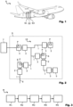
- Fig. 1 shows an illustration of an aircraft A, the fuselage of which is made up of several fuselage sections S1, S2, S3. These fuselage sections S1 to S3 are usually manufactured individually and assembled in a final assembly line to form the fuselage of aircraft A. Electrical cables which run through several of the fuselage sections are connected to one another in the final assembly by suitable plug connections or node elements.
- Fig. 2 shows a schematic block diagram of an exemplary fuselage section S, such as one of the fuselage sections S1 to S3 of the Fig. 1 , in which a wiring harness test system 10 is installed.
- the wiring harness test system 10 can be used during the manufacture of the fuselage section S and in particular during and after
- the cable harness test system 10 is used to monitor one or more cable harnesses to be installed in the fuselage section S so that any defects or errors that occur, such as cable breaks, short circuits, loose contacts, incorrect wiring and/or open lines, can be detected and rectified immediately or as soon as they occur. If a defect or error is detected, the cable harness test system 10 can provide a person entrusted with the manufacture of the fuselage section S with information about the defect or error, together with a description of the defect or error and an acoustic and/or optical warning signal. This person can then react directly to the detected defect or error. By dealing with the defect or error promptly, the time until the error is rectified can be significantly reduced.
- any defects or errors that occur such as cable breaks, short circuits, loose contacts, incorrect wiring and/or open lines
- the wiring harness test system 10 can remain in the fuselage section S during the production of other areas of the fuselage section S until the fuselage section S is ready for final acceptance or transport to final assembly. Until then, the wiring harness test system 10 can continuously monitor the functionality of the wires of the wiring harness and the entire electrical wiring of the fuselage section S. Separate final acceptance tests with external wiring harness testers are no longer absolutely necessary thanks to the wiring harness test system 10.
- the cable harness test system 10 comprises a cable test device 4 and several interface simulation devices 5 and 6.
- the cable test device 4 serves as a central network element and has a microcomputer P for generating, analyzing and forwarding a large number of different line test signals that can be adapted to the type of cable harness to be tested.
- Lines 1 of a cable harness can be connected to the cable test device 4 with their first end points 2 via a large number of first test point connections.
- the first end points 2 can have suitable adapters, interface connections or connectors.
- Interface simulation devices 5 and 6 are then connected to the respective end points 3 of the cables opposite the first end points 2.
- the interface simulation devices 5 and 6 can be connected via second test point connections via which the second end points 3 of the plurality of electrical lines 1 of the wiring harness can be connected, for example via corresponding connectors, adapters or interface connections, depending on the type and functionality of the lines 1.
- Fig. 2 various possible variants for the interface simulation devices are shown.
- Some of the interface simulation devices 5, like the cable test device 4, can have a microcomputer P, which can simulate terminal devices to be connected to the second end points 3.
- Some of the interface simulation devices 5, however, can only have analog circuits, such as diode circuits, analog filters or terminating resistors, in order to simulate corresponding electrical behavior at the second end points 3.
- Still other interface simulation devices 6 can have a microcomputer P and be suitable for passing signals through to further line sections 1 of the cable harness.
- the interface simulation devices 6 can, for example, have third test point connections, via which lines 1 can be connected to their first end points 2.
- Further interface simulation devices, such as interface simulation devices 5 with microcomputers P or only with analog circuits can in turn be connected to these lines 1 at their second end points 3.
- the cable test device 4 can transmit line test signals through the resulting network of lines 1. These line test signals can be generated adaptably by the cable test device 4 and fed into the plurality of electrical lines 1 of the cable harness via the first test point connections.
- the interface simulation devices 5, 6 each receive one of the line test signals via the respective connected line 1 and send suitable response signals to the line test signals back to the cable test device 4.
- the line test signals can be sent back via the second test point connections and the corresponding electrical lines 1 of the cable harness.
- the cable test device 4 can either evaluate the received returned line test signals itself or forward them to a monitoring computer 7, such as a PC, a laptop or a mobile Communication device.
- the monitoring computer 7 is coupled to the cable test device 4 and can be arranged, for example, outside the fuselage section S in order to provide a person entrusted with production with easier access to the required information.
- the monitoring computer 7 evaluates the line test signals sent back from the interface simulation devices 5, 6 to the cable test device 4, for example by detecting defects or errors in the lines 1 of the cable harness depending on the line test signals sent back from the interface simulation devices 5, 6 to the cable test device 4.
- Information signals about the detected defects or errors can be output to operators via the (not explicitly shown) output unit of the monitoring computer 7, such as acoustic and/or optical warning signals as well as descriptions and classifications of the detected defects or errors.
- Fig. 3 illustrates stages of an exemplary test method M for checking a cable harness to be installed in an aircraft component such as a fuselage section S.
- a cable test device 4 with a microcomputer P and a plurality of first test point connections is connected to first end points 2 of a plurality of electrical lines 1 of the cable harness.
- a plurality of interface simulation devices 5, 6, each with a plurality of second test point connections are then connected to second end points 3 of the plurality of electrical lines 1 of the cable harness.
- This connection of the cable test device 4 and the plurality of interface simulation devices 5, 6 can take place, for example, after a complete or partial installation of the cable harness in the aircraft component S.
- the cable test device 4 feeds line test signals into the plurality of electrical lines 1 of the cable harness, which are received in a fourth step M4 at the plurality of interface simulation devices 5, 6 and sent back to the cable test device 4 through the plurality of electrical lines 1 of the cable harness.
- line test signals sent back to the cable test device 4 by the plurality of interface simulation devices 5, 6 can be evaluated by a monitoring computer 7.
- the monitoring computer 7 can, for example, detect defects or errors in the lines 1 of the cable harness depending on the signals received from the plurality of interface simulation devices 5, 6. Detect line test signals sent back to the cable test device 4 by interface simulation devices 5, 6.
- the monitoring computer 7 can output information signals about the detected defects or errors to an operator of the monitoring computer 7, such as acoustic and/or optical warning signals as well as descriptions and classifications of the detected defects or errors, for example detected cable breaks, short circuits, loose contacts, incorrect wiring and/or open lines.
Landscapes
- Physics & Mathematics (AREA)
- Engineering & Computer Science (AREA)
- General Physics & Mathematics (AREA)
- Manufacturing & Machinery (AREA)
- Transportation (AREA)
- Aviation & Aerospace Engineering (AREA)
- Mathematical Physics (AREA)
- Theoretical Computer Science (AREA)
- Testing Of Short-Circuits, Discontinuities, Leakage, Or Incorrect Line Connections (AREA)
Claims (4)
- Système de test de faisceaux de câbles (10) comprenantun testeur de câble (4), lequel possède un micro-ordinateur (P) et une pluralité de premières bornes de point de test servant à connecter des premiers points d'extrémité (2) d'une pluralité de lignes électriques (1) d'un faisceau de câbles et est conçu pour injecter des signaux de test de ligne au niveau des premières bornes de point de test dans la pluralité de lignes électriques (1) du faisceau de câbles, les signaux de test de ligne pouvant être générés par le testeur de câble (4) de manière adaptable à des lignes respectives de la pluralité de lignes électriques (1) du faisceau de câbles ; etune pluralité d'appareils de simulation d'interface (5, 6), lesquels comprennent respectivement une pluralité de deuxièmes bornes de point de test servant à connecter des deuxièmes points d'extrémité (3) de la pluralité de lignes électriques (1) du faisceau de câbles et sont respectivement conçus pour renvoyer les signaux de test de ligne reçus par le testeur de câble (4) au niveau des deuxièmes bornes de point de test au testeur de câble (4) à travers la pluralité de lignes électriques (1) du faisceau de câbles,le testeur de câble (4) étant en outre conçu pour évaluer les signaux de test de ligne renvoyés au testeur de câble (4) par la pluralité d'appareils de simulation d'interface (5, 6).
- Système de test de faisceaux de câbles (10) selon la revendication 1, au moins certains de la pluralité d'appareils de simulation d'interface (5, 6) possédant des micro-ordinateurs (P).
- Système de test de faisceaux de câbles (10) selon les revendications 1 et 2, au moins certains de la pluralité d'appareils de simulation d'interface (5, 6) possédant uniquement des circuits analogiques.
- Procédé de test (M) pour vérifier un faisceau de câbles à installer dans un composant d'aéronef (S), comprenant :raccordement (M1) d'un testeur de câble (4) comprenant un micro-ordinateur (P) et une pluralité de premières bornes de points de test à des premiers points d'extrémité (2) d'une pluralité de lignes électriques (1) du faisceau de câbles ;raccordement (M2) d'une pluralité d'appareils de simulation d'interface (5, 6) comprenant respectivement une pluralité de deuxièmes bornes de point de test à des deuxièmes points d'extrémité (3) de la pluralité de lignes électriques (1) du faisceau de câbles, le raccordement du testeur de câble (4) et de la pluralité d'appareils de simulation d'interface (5, 6) à la pluralité de lignes électriques (1) du faisceau de câbles étant effectué après une installation du faisceau de câbles dans le composant d'aéronef (S) ;injection (M3) de signaux de test de ligne dans la pluralité de lignes électriques (1) du faisceau de câbles par le testeur de câble (4) ;renvoi (M4) des signaux de test de ligne reçus par le testeur de câble (4) au niveau de la pluralité d'appareils de simulation d'interface (5, 6) au testeur de câble (4) par le biais de la pluralité de lignes électriques (1) du faisceau de câbles ; etévaluation (M5), par le testeur de câble (4), des signaux de test de ligne renvoyés au testeur de câble (4) par la pluralité d'appareils de simulation d'interface (5, 6).
Applications Claiming Priority (1)
| Application Number | Priority Date | Filing Date | Title |
|---|---|---|---|
| DE102018214326.9A DE102018214326A1 (de) | 2018-08-24 | 2018-08-24 | Kabelbaumtestsystem und Testverfahren zum Überprüfen von Kabelbäumen |
Publications (2)
| Publication Number | Publication Date |
|---|---|
| EP3614154A1 EP3614154A1 (fr) | 2020-02-26 |
| EP3614154B1 true EP3614154B1 (fr) | 2024-10-16 |
Family
ID=67438702
Family Applications (1)
| Application Number | Title | Priority Date | Filing Date |
|---|---|---|---|
| EP19188065.7A Active EP3614154B1 (fr) | 2018-08-24 | 2019-07-24 | Système de faisceaux de câbles et procédé de vérification de faisceaux de câbles |
Country Status (4)
| Country | Link |
|---|---|
| US (1) | US11442095B2 (fr) |
| EP (1) | EP3614154B1 (fr) |
| CN (1) | CN110895313A (fr) |
| DE (1) | DE102018214326A1 (fr) |
Families Citing this family (11)
| Publication number | Priority date | Publication date | Assignee | Title |
|---|---|---|---|---|
| US10996286B2 (en) * | 2018-11-29 | 2021-05-04 | The Boeing Company | Test system and method for a wiring harness |
| FR3114876B1 (fr) * | 2020-10-06 | 2022-11-04 | Safran Aircraft Engines | Diagnostic d’un calculateur moteur d’aeronef |
| FR3114877B1 (fr) | 2020-10-06 | 2022-11-04 | Safran Aircraft Engines | Diagnostic d’un calculateur moteur d’aeronef |
| CN112444417B (zh) * | 2020-11-12 | 2023-01-31 | 杭州中车车辆有限公司 | 一种跨接线试验系统和跨接线模拟试验工装 |
| US11874318B2 (en) * | 2021-08-27 | 2024-01-16 | Hamilton Sundstrand Corporation | Online health monitoring and fault detection for high voltage DC distribution networks |
| US12413098B2 (en) | 2023-09-15 | 2025-09-09 | Lockheed Martin Corporation | Systems and methods for a charging cart of a wireless harness automated measurement system |
| US12578359B2 (en) | 2023-09-15 | 2026-03-17 | Lockheed Martin Corporation | Wireless harness automated measurement systems and methods |
| US12607668B2 (en) | 2023-09-15 | 2026-04-21 | Lockheed Martin Corporation | Systems and methods for wireless test modules of a wireless harness automated measurement system |
| US12498399B2 (en) | 2023-09-15 | 2025-12-16 | Lockheed Martin Corporation | Systems and methods for calibrating a wireless harness automated measurement system |
| US12450997B2 (en) * | 2023-10-04 | 2025-10-21 | Panasonic Avionics Corporation | Methods and systems for monitoring for faulty connector receiver modules of media playback devices in a transportation vehicle |
| CN118938081B (zh) * | 2024-08-01 | 2026-03-03 | 武汉联镇科技有限公司 | 线束测试工作台 |
Citations (1)
| Publication number | Priority date | Publication date | Assignee | Title |
|---|---|---|---|---|
| DE102011087152B4 (de) * | 2011-11-25 | 2013-08-14 | Digalog Industrie-Mikroelektronik Gmbh | Testsystem und Testverfahren für Kabelbäume |
Family Cites Families (9)
| Publication number | Priority date | Publication date | Assignee | Title |
|---|---|---|---|---|
| US4218745A (en) * | 1978-09-11 | 1980-08-19 | Lockheed Corporation | Microcomputer assisted electrical harness fabrication and testing system |
| US5036479A (en) * | 1989-04-20 | 1991-07-30 | Trw Inc. | Modular automated avionics test system |
| US4951385A (en) * | 1989-05-16 | 1990-08-28 | Desanto Joseph J | Electrical harness assembly apparatus |
| US5268644A (en) * | 1990-04-03 | 1993-12-07 | Ford Motor Company | Fault detection and isolation in automotive wiring harness by time-domain reflectometry |
| JPH09189740A (ja) * | 1996-01-10 | 1997-07-22 | Harness Sogo Gijutsu Kenkyusho:Kk | ワイヤーハーネスの故障位置検出装置 |
| US6442498B1 (en) * | 1999-06-15 | 2002-08-27 | Henrick Youval Krigel | Apparatus and method for determining the integrity of cables and wiring harnesses |
| US8423305B2 (en) * | 2009-12-23 | 2013-04-16 | The Boeing Company | Wire system assessment |
| DE102012200115B4 (de) | 2012-01-05 | 2018-12-27 | Airbus Operations Gmbh | Prüfsystem für Steckverbinder, Luft- oder Raumfahrzeug und Verfahren |
| FR3056966B1 (fr) * | 2016-10-04 | 2018-10-05 | Safran Electrical & Power | Procede de localisation de defaut dans des harnais electriques |
-
2018
- 2018-08-24 DE DE102018214326.9A patent/DE102018214326A1/de not_active Withdrawn
-
2019
- 2019-07-24 EP EP19188065.7A patent/EP3614154B1/fr active Active
- 2019-08-09 US US16/536,775 patent/US11442095B2/en active Active
- 2019-08-23 CN CN201910783832.8A patent/CN110895313A/zh active Pending
Patent Citations (1)
| Publication number | Priority date | Publication date | Assignee | Title |
|---|---|---|---|---|
| DE102011087152B4 (de) * | 2011-11-25 | 2013-08-14 | Digalog Industrie-Mikroelektronik Gmbh | Testsystem und Testverfahren für Kabelbäume |
Also Published As
| Publication number | Publication date |
|---|---|
| EP3614154A1 (fr) | 2020-02-26 |
| CN110895313A (zh) | 2020-03-20 |
| US11442095B2 (en) | 2022-09-13 |
| US20200064387A1 (en) | 2020-02-27 |
| DE102018214326A1 (de) | 2020-02-27 |
Similar Documents
| Publication | Publication Date | Title |
|---|---|---|
| EP3614154B1 (fr) | Système de faisceaux de câbles et procédé de vérification de faisceaux de câbles | |
| DE69432829T2 (de) | Kabelidentifizierungsgerät zum Prüfen von Kabeln in lokalen Netzen | |
| DE102007010978A1 (de) | Verfahren und Vorrichtung zur Unterstützung einer Diagnose eines elektrischen Systems mittels wahrscheinlichkeitsbasierter Fehlerkandidatenermittlung | |
| DE102021104593A1 (de) | Elektronisches reparatur- und diagnosesystem und -verfahren für ein fahrzeug | |
| DE102009031892B4 (de) | Prüfsystem zum Prüfen einer Leitungsanordnung, Verwendung eines Adapters in einem Prüfsystem und Prüfgerät zum Prüfen einer Leitungsanordnung sowie Verfahren zum Herstellen einer Leitungsanordnung | |
| DE102004004572A1 (de) | Fehlerdiagnoseverfahren für ein Fahrzeugkommunikationsnetz | |
| WO2020025399A1 (fr) | Dispositif et procédé servant à vérifier un contenu d'armoire de distribution selon un montage basé sur une planification | |
| DE19507959C1 (de) | Vorrichtung zur Strommessung an einer Hauptstromleitung eines Fahrzeug-Bordnetzes | |
| DE102014008750A1 (de) | Verbindungsprüfverfahren und verbindungsprüfvorrichtung | |
| DE102012200115B4 (de) | Prüfsystem für Steckverbinder, Luft- oder Raumfahrzeug und Verfahren | |
| DE102017113413B4 (de) | Vorrichtung, verfahren, herstellverfahren | |
| DE102021126666B4 (de) | Test von Kabelbäumen mit mechanisch empfindlichen Kontaktenden | |
| EP1795858B1 (fr) | Unité de test de station d'armement et procédé pour tester la disponibilité d'une station d'armement d'un aéronef | |
| DE102005055429B4 (de) | Verfahren und Vorrichtung zur Diagnose eines Bussystems mit einer Anzahl von Busteilnehmern | |
| DE102021117505B3 (de) | Vorrichtung und Verfahren zur automatisierten Fehlerreaktionssimulation | |
| DE102022213021B3 (de) | Überwachen einer Schaltanlage | |
| DE102007015140A1 (de) | Diagnosevorrichtung und Diagnoseverfahren zum Ausführen einer Diagnose eines mechatronischen Systems | |
| WO2018114184A1 (fr) | Procédé et unité de commande pour éliminer des défaillances dans une installation de la technologie d'automatisation | |
| DE102007020480A1 (de) | Verfahren zum Überprüfen einer Kommunikationsverbindung | |
| EP3807660B1 (fr) | Procédé et dispositif de vérification électrique d'un module électrique | |
| DE102019126470A1 (de) | Verfahren und system zur herstellung eines leitungssatzes | |
| EP3899558A1 (fr) | Procédé et dispositif de contrôle | |
| DE102017111273B3 (de) | Vorrichtung und Verfahren zum Überprüfen von Datenleitungen in Kabelbäumen und Herstellungsverfahren für in einem Kabelbaum angeordnete Datenleitungen | |
| DE102024200772B3 (de) | Verfahren zum bestimmen eines zustands eines prüfstands, computerpogramm, steuervorrichtung und prüfstand | |
| DE102024204161A1 (de) | Verfahren zum Prüfen eines Kabelsatzes |
Legal Events
| Date | Code | Title | Description |
|---|---|---|---|
| PUAI | Public reference made under article 153(3) epc to a published international application that has entered the european phase |
Free format text: ORIGINAL CODE: 0009012 |
|
| STAA | Information on the status of an ep patent application or granted ep patent |
Free format text: STATUS: THE APPLICATION HAS BEEN PUBLISHED |
|
| AK | Designated contracting states |
Kind code of ref document: A1 Designated state(s): AL AT BE BG CH CY CZ DE DK EE ES FI FR GB GR HR HU IE IS IT LI LT LU LV MC MK MT NL NO PL PT RO RS SE SI SK SM TR |
|
| AX | Request for extension of the european patent |
Extension state: BA ME |
|
| STAA | Information on the status of an ep patent application or granted ep patent |
Free format text: STATUS: REQUEST FOR EXAMINATION WAS MADE |
|
| 17P | Request for examination filed |
Effective date: 20200729 |
|
| RBV | Designated contracting states (corrected) |
Designated state(s): AL AT BE BG CH CY CZ DE DK EE ES FI FR GB GR HR HU IE IS IT LI LT LU LV MC MK MT NL NO PL PT RO RS SE SI SK SM TR |
|
| STAA | Information on the status of an ep patent application or granted ep patent |
Free format text: STATUS: EXAMINATION IS IN PROGRESS |
|
| 17Q | First examination report despatched |
Effective date: 20221006 |
|
| REG | Reference to a national code |
Ref country code: DE Ref legal event code: R079 Free format text: PREVIOUS MAIN CLASS: G01R0031000000 Ipc: G01R0031580000 Ref country code: DE Ref legal event code: R079 Ref document number: 502019012296 Country of ref document: DE Free format text: PREVIOUS MAIN CLASS: G01R0031000000 Ipc: G01R0031580000 |
|
| GRAP | Despatch of communication of intention to grant a patent |
Free format text: ORIGINAL CODE: EPIDOSNIGR1 |
|
| STAA | Information on the status of an ep patent application or granted ep patent |
Free format text: STATUS: GRANT OF PATENT IS INTENDED |
|
| RIC1 | Information provided on ipc code assigned before grant |
Ipc: G01R 31/58 20200101AFI20240524BHEP |
|
| INTG | Intention to grant announced |
Effective date: 20240619 |
|
| GRAS | Grant fee paid |
Free format text: ORIGINAL CODE: EPIDOSNIGR3 |
|
| GRAA | (expected) grant |
Free format text: ORIGINAL CODE: 0009210 |
|
| STAA | Information on the status of an ep patent application or granted ep patent |
Free format text: STATUS: THE PATENT HAS BEEN GRANTED |
|
| AK | Designated contracting states |
Kind code of ref document: B1 Designated state(s): AL AT BE BG CH CY CZ DE DK EE ES FI FR GB GR HR HU IE IS IT LI LT LU LV MC MK MT NL NO PL PT RO RS SE SI SK SM TR |
|
| REG | Reference to a national code |
Ref country code: GB Ref legal event code: FG4D Free format text: NOT ENGLISH |
|
| REG | Reference to a national code |
Ref country code: DE Ref legal event code: R096 Ref document number: 502019012296 Country of ref document: DE Ref country code: CH Ref legal event code: EP |
|
| REG | Reference to a national code |
Ref country code: IE Ref legal event code: FG4D Free format text: LANGUAGE OF EP DOCUMENT: GERMAN |
|
| REG | Reference to a national code |
Ref country code: LT Ref legal event code: MG9D |
|
| REG | Reference to a national code |
Ref country code: NL Ref legal event code: MP Effective date: 20241016 |
|
| PG25 | Lapsed in a contracting state [announced via postgrant information from national office to epo] |
Ref country code: NL Free format text: LAPSE BECAUSE OF FAILURE TO SUBMIT A TRANSLATION OF THE DESCRIPTION OR TO PAY THE FEE WITHIN THE PRESCRIBED TIME-LIMIT Effective date: 20241016 |
|
| PG25 | Lapsed in a contracting state [announced via postgrant information from national office to epo] |
Ref country code: NL Free format text: LAPSE BECAUSE OF FAILURE TO SUBMIT A TRANSLATION OF THE DESCRIPTION OR TO PAY THE FEE WITHIN THE PRESCRIBED TIME-LIMIT Effective date: 20241016 |
|
| PG25 | Lapsed in a contracting state [announced via postgrant information from national office to epo] |
Ref country code: HR Free format text: LAPSE BECAUSE OF FAILURE TO SUBMIT A TRANSLATION OF THE DESCRIPTION OR TO PAY THE FEE WITHIN THE PRESCRIBED TIME-LIMIT Effective date: 20241016 Ref country code: PT Free format text: LAPSE BECAUSE OF FAILURE TO SUBMIT A TRANSLATION OF THE DESCRIPTION OR TO PAY THE FEE WITHIN THE PRESCRIBED TIME-LIMIT Effective date: 20250217 Ref country code: IS Free format text: LAPSE BECAUSE OF FAILURE TO SUBMIT A TRANSLATION OF THE DESCRIPTION OR TO PAY THE FEE WITHIN THE PRESCRIBED TIME-LIMIT Effective date: 20250216 |
|
| PG25 | Lapsed in a contracting state [announced via postgrant information from national office to epo] |
Ref country code: FI Free format text: LAPSE BECAUSE OF FAILURE TO SUBMIT A TRANSLATION OF THE DESCRIPTION OR TO PAY THE FEE WITHIN THE PRESCRIBED TIME-LIMIT Effective date: 20241016 |
|
| PG25 | Lapsed in a contracting state [announced via postgrant information from national office to epo] |
Ref country code: BG Free format text: LAPSE BECAUSE OF FAILURE TO SUBMIT A TRANSLATION OF THE DESCRIPTION OR TO PAY THE FEE WITHIN THE PRESCRIBED TIME-LIMIT Effective date: 20241016 |
|
| PG25 | Lapsed in a contracting state [announced via postgrant information from national office to epo] |
Ref country code: ES Free format text: LAPSE BECAUSE OF FAILURE TO SUBMIT A TRANSLATION OF THE DESCRIPTION OR TO PAY THE FEE WITHIN THE PRESCRIBED TIME-LIMIT Effective date: 20241016 |
|
| PG25 | Lapsed in a contracting state [announced via postgrant information from national office to epo] |
Ref country code: NO Free format text: LAPSE BECAUSE OF FAILURE TO SUBMIT A TRANSLATION OF THE DESCRIPTION OR TO PAY THE FEE WITHIN THE PRESCRIBED TIME-LIMIT Effective date: 20250116 |
|
| PG25 | Lapsed in a contracting state [announced via postgrant information from national office to epo] |
Ref country code: LV Free format text: LAPSE BECAUSE OF FAILURE TO SUBMIT A TRANSLATION OF THE DESCRIPTION OR TO PAY THE FEE WITHIN THE PRESCRIBED TIME-LIMIT Effective date: 20241016 Ref country code: GR Free format text: LAPSE BECAUSE OF FAILURE TO SUBMIT A TRANSLATION OF THE DESCRIPTION OR TO PAY THE FEE WITHIN THE PRESCRIBED TIME-LIMIT Effective date: 20250117 |
|
| PG25 | Lapsed in a contracting state [announced via postgrant information from national office to epo] |
Ref country code: PL Free format text: LAPSE BECAUSE OF FAILURE TO SUBMIT A TRANSLATION OF THE DESCRIPTION OR TO PAY THE FEE WITHIN THE PRESCRIBED TIME-LIMIT Effective date: 20241016 |
|
| PG25 | Lapsed in a contracting state [announced via postgrant information from national office to epo] |
Ref country code: RS Free format text: LAPSE BECAUSE OF FAILURE TO SUBMIT A TRANSLATION OF THE DESCRIPTION OR TO PAY THE FEE WITHIN THE PRESCRIBED TIME-LIMIT Effective date: 20250116 |
|
| PG25 | Lapsed in a contracting state [announced via postgrant information from national office to epo] |
Ref country code: SM Free format text: LAPSE BECAUSE OF FAILURE TO SUBMIT A TRANSLATION OF THE DESCRIPTION OR TO PAY THE FEE WITHIN THE PRESCRIBED TIME-LIMIT Effective date: 20241016 |
|
| PG25 | Lapsed in a contracting state [announced via postgrant information from national office to epo] |
Ref country code: DK Free format text: LAPSE BECAUSE OF FAILURE TO SUBMIT A TRANSLATION OF THE DESCRIPTION OR TO PAY THE FEE WITHIN THE PRESCRIBED TIME-LIMIT Effective date: 20241016 |
|
| REG | Reference to a national code |
Ref country code: DE Ref legal event code: R097 Ref document number: 502019012296 Country of ref document: DE |
|
| PG25 | Lapsed in a contracting state [announced via postgrant information from national office to epo] |
Ref country code: EE Free format text: LAPSE BECAUSE OF FAILURE TO SUBMIT A TRANSLATION OF THE DESCRIPTION OR TO PAY THE FEE WITHIN THE PRESCRIBED TIME-LIMIT Effective date: 20241016 |
|
| PG25 | Lapsed in a contracting state [announced via postgrant information from national office to epo] |
Ref country code: RO Free format text: LAPSE BECAUSE OF FAILURE TO SUBMIT A TRANSLATION OF THE DESCRIPTION OR TO PAY THE FEE WITHIN THE PRESCRIBED TIME-LIMIT Effective date: 20241016 |
|
| PG25 | Lapsed in a contracting state [announced via postgrant information from national office to epo] |
Ref country code: SK Free format text: LAPSE BECAUSE OF FAILURE TO SUBMIT A TRANSLATION OF THE DESCRIPTION OR TO PAY THE FEE WITHIN THE PRESCRIBED TIME-LIMIT Effective date: 20241016 |
|
| PG25 | Lapsed in a contracting state [announced via postgrant information from national office to epo] |
Ref country code: CZ Free format text: LAPSE BECAUSE OF FAILURE TO SUBMIT A TRANSLATION OF THE DESCRIPTION OR TO PAY THE FEE WITHIN THE PRESCRIBED TIME-LIMIT Effective date: 20241016 |
|
| PLBE | No opposition filed within time limit |
Free format text: ORIGINAL CODE: 0009261 |
|
| STAA | Information on the status of an ep patent application or granted ep patent |
Free format text: STATUS: NO OPPOSITION FILED WITHIN TIME LIMIT |
|
| PG25 | Lapsed in a contracting state [announced via postgrant information from national office to epo] |
Ref country code: SE Free format text: LAPSE BECAUSE OF FAILURE TO SUBMIT A TRANSLATION OF THE DESCRIPTION OR TO PAY THE FEE WITHIN THE PRESCRIBED TIME-LIMIT Effective date: 20241016 |
|
| 26N | No opposition filed |
Effective date: 20250717 |
|
| PGFP | Annual fee paid to national office [announced via postgrant information from national office to epo] |
Ref country code: DE Payment date: 20250722 Year of fee payment: 7 |
|
| PGFP | Annual fee paid to national office [announced via postgrant information from national office to epo] |
Ref country code: IT Payment date: 20250724 Year of fee payment: 7 |
|
| PGFP | Annual fee paid to national office [announced via postgrant information from national office to epo] |
Ref country code: GB Payment date: 20250722 Year of fee payment: 7 |
|
| PGFP | Annual fee paid to national office [announced via postgrant information from national office to epo] |
Ref country code: FR Payment date: 20250725 Year of fee payment: 7 Ref country code: AT Payment date: 20250722 Year of fee payment: 7 |
|
| REG | Reference to a national code |
Ref country code: CH Ref legal event code: H13 Free format text: ST27 STATUS EVENT CODE: U-0-0-H10-H13 (AS PROVIDED BY THE NATIONAL OFFICE) Effective date: 20260224 |
|
| PG25 | Lapsed in a contracting state [announced via postgrant information from national office to epo] |
Ref country code: LU Free format text: LAPSE BECAUSE OF NON-PAYMENT OF DUE FEES Effective date: 20250724 |
|
| REG | Reference to a national code |
Ref country code: BE Ref legal event code: MM Effective date: 20250731 |
|
| PG25 | Lapsed in a contracting state [announced via postgrant information from national office to epo] |
Ref country code: BE Free format text: LAPSE BECAUSE OF NON-PAYMENT OF DUE FEES Effective date: 20250731 |