EP3614224B1 - Procédé et dispositif de commande de véhicule, et véhicule support de stockage - Google Patents
Procédé et dispositif de commande de véhicule, et véhicule support de stockage Download PDFInfo
- Publication number
- EP3614224B1 EP3614224B1 EP18869117.4A EP18869117A EP3614224B1 EP 3614224 B1 EP3614224 B1 EP 3614224B1 EP 18869117 A EP18869117 A EP 18869117A EP 3614224 B1 EP3614224 B1 EP 3614224B1
- Authority
- EP
- European Patent Office
- Prior art keywords
- vehicle
- amount
- braking
- control mode
- throttle
- Prior art date
- Legal status (The legal status is an assumption and is not a legal conclusion. Google has not performed a legal analysis and makes no representation as to the accuracy of the status listed.)
- Active
Links
Images





Classifications
-
- G—PHYSICS
- G05—CONTROLLING; REGULATING
- G05D—SYSTEMS FOR CONTROLLING OR REGULATING NON-ELECTRIC VARIABLES
- G05D1/00—Control of position, course, altitude or attitude of land, water, air or space vehicles, e.g. using automatic pilots
- G05D1/02—Control of position or course in two dimensions
- G05D1/021—Control of position or course in two dimensions specially adapted to land vehicles
- G05D1/0259—Control of position or course in two dimensions specially adapted to land vehicles using magnetic or electromagnetic means
-
- B—PERFORMING OPERATIONS; TRANSPORTING
- B60—VEHICLES IN GENERAL
- B60W—CONJOINT CONTROL OF VEHICLE SUB-UNITS OF DIFFERENT TYPE OR DIFFERENT FUNCTION; CONTROL SYSTEMS SPECIALLY ADAPTED FOR HYBRID VEHICLES; ROAD VEHICLE DRIVE CONTROL SYSTEMS FOR PURPOSES NOT RELATED TO THE CONTROL OF A PARTICULAR SUB-UNIT
- B60W30/00—Purposes of road vehicle drive control systems not related to the control of a particular sub-unit, e.g. of systems using conjoint control of vehicle sub-units
- B60W30/14—Adaptive cruise control
- B60W30/143—Speed control
-
- B—PERFORMING OPERATIONS; TRANSPORTING
- B60—VEHICLES IN GENERAL
- B60W—CONJOINT CONTROL OF VEHICLE SUB-UNITS OF DIFFERENT TYPE OR DIFFERENT FUNCTION; CONTROL SYSTEMS SPECIALLY ADAPTED FOR HYBRID VEHICLES; ROAD VEHICLE DRIVE CONTROL SYSTEMS FOR PURPOSES NOT RELATED TO THE CONTROL OF A PARTICULAR SUB-UNIT
- B60W10/00—Conjoint control of vehicle sub-units of different type or different function
- B60W10/18—Conjoint control of vehicle sub-units of different type or different function including control of braking systems
-
- B—PERFORMING OPERATIONS; TRANSPORTING
- B60—VEHICLES IN GENERAL
- B60W—CONJOINT CONTROL OF VEHICLE SUB-UNITS OF DIFFERENT TYPE OR DIFFERENT FUNCTION; CONTROL SYSTEMS SPECIALLY ADAPTED FOR HYBRID VEHICLES; ROAD VEHICLE DRIVE CONTROL SYSTEMS FOR PURPOSES NOT RELATED TO THE CONTROL OF A PARTICULAR SUB-UNIT
- B60W10/00—Conjoint control of vehicle sub-units of different type or different function
- B60W10/04—Conjoint control of vehicle sub-units of different type or different function including control of propulsion units
-
- B—PERFORMING OPERATIONS; TRANSPORTING
- B60—VEHICLES IN GENERAL
- B60W—CONJOINT CONTROL OF VEHICLE SUB-UNITS OF DIFFERENT TYPE OR DIFFERENT FUNCTION; CONTROL SYSTEMS SPECIALLY ADAPTED FOR HYBRID VEHICLES; ROAD VEHICLE DRIVE CONTROL SYSTEMS FOR PURPOSES NOT RELATED TO THE CONTROL OF A PARTICULAR SUB-UNIT
- B60W10/00—Conjoint control of vehicle sub-units of different type or different function
- B60W10/04—Conjoint control of vehicle sub-units of different type or different function including control of propulsion units
- B60W10/06—Conjoint control of vehicle sub-units of different type or different function including control of propulsion units including control of combustion engines
-
- B—PERFORMING OPERATIONS; TRANSPORTING
- B60—VEHICLES IN GENERAL
- B60W—CONJOINT CONTROL OF VEHICLE SUB-UNITS OF DIFFERENT TYPE OR DIFFERENT FUNCTION; CONTROL SYSTEMS SPECIALLY ADAPTED FOR HYBRID VEHICLES; ROAD VEHICLE DRIVE CONTROL SYSTEMS FOR PURPOSES NOT RELATED TO THE CONTROL OF A PARTICULAR SUB-UNIT
- B60W50/00—Details of control systems for road vehicle drive control not related to the control of a particular sub-unit, e.g. process diagnostic or vehicle driver interfaces
- B60W50/0097—Predicting future conditions
-
- B—PERFORMING OPERATIONS; TRANSPORTING
- B60—VEHICLES IN GENERAL
- B60W—CONJOINT CONTROL OF VEHICLE SUB-UNITS OF DIFFERENT TYPE OR DIFFERENT FUNCTION; CONTROL SYSTEMS SPECIALLY ADAPTED FOR HYBRID VEHICLES; ROAD VEHICLE DRIVE CONTROL SYSTEMS FOR PURPOSES NOT RELATED TO THE CONTROL OF A PARTICULAR SUB-UNIT
- B60W60/00—Drive control systems specially adapted for autonomous road vehicles
- B60W60/001—Planning or execution of driving tasks
-
- G—PHYSICS
- G05—CONTROLLING; REGULATING
- G05D—SYSTEMS FOR CONTROLLING OR REGULATING NON-ELECTRIC VARIABLES
- G05D1/00—Control of position, course, altitude or attitude of land, water, air or space vehicles, e.g. using automatic pilots
- G05D1/02—Control of position or course in two dimensions
- G05D1/021—Control of position or course in two dimensions specially adapted to land vehicles
- G05D1/0212—Control of position or course in two dimensions specially adapted to land vehicles with means for defining a desired trajectory
- G05D1/0214—Control of position or course in two dimensions specially adapted to land vehicles with means for defining a desired trajectory in accordance with safety or protection criteria, e.g. avoiding hazardous areas
-
- G—PHYSICS
- G05—CONTROLLING; REGULATING
- G05D—SYSTEMS FOR CONTROLLING OR REGULATING NON-ELECTRIC VARIABLES
- G05D1/00—Control of position, course, altitude or attitude of land, water, air or space vehicles, e.g. using automatic pilots
- G05D1/02—Control of position or course in two dimensions
- G05D1/021—Control of position or course in two dimensions specially adapted to land vehicles
- G05D1/0212—Control of position or course in two dimensions specially adapted to land vehicles with means for defining a desired trajectory
- G05D1/0221—Control of position or course in two dimensions specially adapted to land vehicles with means for defining a desired trajectory involving a learning process
-
- G—PHYSICS
- G05—CONTROLLING; REGULATING
- G05D—SYSTEMS FOR CONTROLLING OR REGULATING NON-ELECTRIC VARIABLES
- G05D1/00—Control of position, course, altitude or attitude of land, water, air or space vehicles, e.g. using automatic pilots
- G05D1/02—Control of position or course in two dimensions
- G05D1/021—Control of position or course in two dimensions specially adapted to land vehicles
- G05D1/0276—Control of position or course in two dimensions specially adapted to land vehicles using signals provided by a source external to the vehicle
- G05D1/0278—Control of position or course in two dimensions specially adapted to land vehicles using signals provided by a source external to the vehicle using satellite positioning signals, e.g. GPS
-
- G—PHYSICS
- G05—CONTROLLING; REGULATING
- G05D—SYSTEMS FOR CONTROLLING OR REGULATING NON-ELECTRIC VARIABLES
- G05D1/00—Control of position, course, altitude or attitude of land, water, air or space vehicles, e.g. using automatic pilots
- G05D1/02—Control of position or course in two dimensions
- G05D1/021—Control of position or course in two dimensions specially adapted to land vehicles
- G05D1/0276—Control of position or course in two dimensions specially adapted to land vehicles using signals provided by a source external to the vehicle
- G05D1/0285—Control of position or course in two dimensions specially adapted to land vehicles using signals provided by a source external to the vehicle using signals transmitted via a public communication network, e.g. GSM network
-
- B—PERFORMING OPERATIONS; TRANSPORTING
- B60—VEHICLES IN GENERAL
- B60W—CONJOINT CONTROL OF VEHICLE SUB-UNITS OF DIFFERENT TYPE OR DIFFERENT FUNCTION; CONTROL SYSTEMS SPECIALLY ADAPTED FOR HYBRID VEHICLES; ROAD VEHICLE DRIVE CONTROL SYSTEMS FOR PURPOSES NOT RELATED TO THE CONTROL OF A PARTICULAR SUB-UNIT
- B60W2520/00—Input parameters relating to overall vehicle dynamics
- B60W2520/10—Longitudinal speed
-
- B—PERFORMING OPERATIONS; TRANSPORTING
- B60—VEHICLES IN GENERAL
- B60W—CONJOINT CONTROL OF VEHICLE SUB-UNITS OF DIFFERENT TYPE OR DIFFERENT FUNCTION; CONTROL SYSTEMS SPECIALLY ADAPTED FOR HYBRID VEHICLES; ROAD VEHICLE DRIVE CONTROL SYSTEMS FOR PURPOSES NOT RELATED TO THE CONTROL OF A PARTICULAR SUB-UNIT
- B60W2556/00—Input parameters relating to data
- B60W2556/45—External transmission of data to or from the vehicle
-
- B—PERFORMING OPERATIONS; TRANSPORTING
- B60—VEHICLES IN GENERAL
- B60W—CONJOINT CONTROL OF VEHICLE SUB-UNITS OF DIFFERENT TYPE OR DIFFERENT FUNCTION; CONTROL SYSTEMS SPECIALLY ADAPTED FOR HYBRID VEHICLES; ROAD VEHICLE DRIVE CONTROL SYSTEMS FOR PURPOSES NOT RELATED TO THE CONTROL OF A PARTICULAR SUB-UNIT
- B60W2710/00—Output or target parameters relating to a particular sub-units
- B60W2710/06—Combustion engines, Gas turbines
- B60W2710/0605—Throttle position
-
- B—PERFORMING OPERATIONS; TRANSPORTING
- B60—VEHICLES IN GENERAL
- B60W—CONJOINT CONTROL OF VEHICLE SUB-UNITS OF DIFFERENT TYPE OR DIFFERENT FUNCTION; CONTROL SYSTEMS SPECIALLY ADAPTED FOR HYBRID VEHICLES; ROAD VEHICLE DRIVE CONTROL SYSTEMS FOR PURPOSES NOT RELATED TO THE CONTROL OF A PARTICULAR SUB-UNIT
- B60W2720/00—Output or target parameters relating to overall vehicle dynamics
- B60W2720/10—Longitudinal speed
-
- B—PERFORMING OPERATIONS; TRANSPORTING
- B60—VEHICLES IN GENERAL
- B60W—CONJOINT CONTROL OF VEHICLE SUB-UNITS OF DIFFERENT TYPE OR DIFFERENT FUNCTION; CONTROL SYSTEMS SPECIALLY ADAPTED FOR HYBRID VEHICLES; ROAD VEHICLE DRIVE CONTROL SYSTEMS FOR PURPOSES NOT RELATED TO THE CONTROL OF A PARTICULAR SUB-UNIT
- B60W2720/00—Output or target parameters relating to overall vehicle dynamics
- B60W2720/10—Longitudinal speed
- B60W2720/103—Speed profile
Definitions
- the invention relates to communications technologies, and in particular, to a vehicle control method and apparatus, a vehicle, and a storage medium.
- a self-driving car driven by an internal combustion engine or a motor is usually controlled by using a throttle, a transmission structure, a braking structure, and an electronic stability program (ESP) system.
- ESP electronic stability program
- stability of a driving speed of the car affects user experience. How to control the driving speed of the car smoothly is receiving increasingly more attention.
- Embodiments of the invention provide a vehicle control method and apparatus, a vehicle, and a storage medium, which can implement smooth speed control of a self-driving car.
- Control models used in the acceleration control mode include the following types: 6.1) Power system model: a power system model is used in the acceleration control mode to determine a throttle amount that needs to be applied to the vehicle to increase the speed to the target driving speed. According to performance of components (including an internal combustion engine, a clutch, a gearbox, a differential, a throttle valve, and a throttle opening) of a power system of the vehicle, the model represents a linear relationship between different given throttle amounts of the vehicle and accelerations that the vehicle can be driven to implement (where the accelerations are positive values).
- components including an internal combustion engine, a clutch, a gearbox, a differential, a throttle valve, and a throttle opening
- the power system model may be merely a linear relationship, or may have a piecewise attribute according to different gears of the vehicle, that is, the power system model includes successively connected linear relationships corresponding to different gears.
- a first damping factor model represents, according to resistance factors (including a wind resistance, a mechanical friction resistance of the vehicle, and a road resistance), a linear relationship between different resistances in a vehicle driving process and throttle amounts required for controlling the vehicle to keep idling (that is, the engine or motor has no load) in the acceleration control mode.
- Second damping factor model represents, according to resistance factors, a linear relationship between different resistances that the vehicle encounters during driving and minimum braking amounts for keeping a moment balance of the vehicle in the acceleration control mode.
- Control models used in the braking control mode include the following types:
- a throttle controller obtains a corresponding throttle control amount according to a difference between a target driving speed and an actual driving speed and according to an algorithm of the throttle controller.
- a brake controller obtains a corresponding brake control amount according to the speed difference between the target driving speed and the actual driving speed and according to an algorithm of the brake controller.
- the vehicle is controlled by using a throttle alone or controlled by using a brake alone.
- the vehicle is controlled by using the throttle amount or the braking amount alone. Therefore, if the vehicle is controlled by using the throttle alone, the brake control is in a released state, and a vehicle component for the brake control is in a zero initial state.
- the vehicle when stability of the vehicle is controlled by using an ESP system, the vehicle is not only required to have a higher electronic configuration, such as a steering sensor, a wheel sensor, a sideslip sensor, a transverse acceleration sensor, and other devices, but also required to have a lower wind resistance coefficient and stronger power performance, resulting in high implementation costs and low transportability of a self-driving car driven by an internal combustion engine, and further affecting the promotion and application of the self-driving car driven by the internal combustion engine.
- a higher electronic configuration such as a steering sensor, a wheel sensor, a sideslip sensor, a transverse acceleration sensor, and other devices
- the vehicle is controlled by using the throttle amount alone or by using the braking amount alone, so as to track the target speed.
- the self-driving car control solution is not generally applicable to all self-driving cars and has poor smoothness in speed control over the self-driving car.
- control models for controlling autonomous driving of the vehicle are proposed. According to a relationship between the target driving speed and the actual driving speed, a control mode matching the relationship is determined. Based on a control model corresponding to the matching control mode, a throttle amount and a braking amount required for controlling the vehicle are determined. When the vehicle is controlled based on the two control parameters at the same time, that is, the throttle amount and the braking amount, vehicle vibrations generated due to frequent switching between the brake and the throttle can be avoided, thus improving the smoothness of speed control.
- the vehicle control apparatus may be implemented on a vehicle terminal side, implemented on a vehicle side, or implemented on an electronic device side (such as a server) communicating with the vehicle.
- a corresponding storage medium may be disposed on the vehicle terminal side, the vehicle side, or the electronic device side, to correspondingly complete processing on the vehicle terminal side, the vehicle side, or the electronic device side.
- the vehicle terminal described in the embodiments of this application may be implemented in a form of a mobile terminal (a smartphone and a tablet computer), an event data recorder, a navigator, or the like, and is fixed at any position on the vehicle (for example, on window glass or a bridge of the vehicle) through a fixing device.
- the fixing device may be flexibly disposed at any position in the internal space of the vehicle as required by means of suction based on a vacuum chuck, suction based on a magnetic element, fastening based on a bolt and a nut, engagement based on a clip, and binding based on a strap.
- the vehicle control apparatus described in the following embodiments of this application may also be embedded into the vehicle to avoid occupying extra space.
- a vehicle terminal 100 in the schematic diagram of a vehicle terminal fixed in a vehicle shown in FIG. 1-1 , a vehicle terminal 100 is fixed on a front window of a vehicle 200 through a fixing device 300 (including a chuck 301 and a support arm 302) by means of the chuck.
- the height of the vehicle terminal 100 may be adjusted by adjusting the support arm 302 in the fixing device 300, so that a user can view a screen of the vehicle terminal 100 conveniently.
- the vehicle terminal 100 in another schematic diagram of a vehicle terminal fixed in the vehicle shown in FIG. 1-2 , the vehicle terminal 100 is embedded into a front panel of the vehicle 200 and forms a streamlined entirety with the internal structure of the vehicle 200, to save internal space of the vehicle 200.
- FIG. 2 is a schematic diagram of a software and hardware structure of the vehicle terminal 100 that includes a hardware layer 11, an operating system layer 12, and an application layer 13, which are described separately.
- a memory 112 may be provided as various forms of non-volatile memories, for example, a read-only memory (ROM), a programmable read-only memory (PROM), or an erasable programmable read-only memory (EPROM), and is configured to store various types of data. Examples of such data include: any computer program to be operated on the vehicle terminal 100. An executable program corresponding to the vehicle control method according to the embodiment of this application may be stored in the memory 112 in advance.
- ROM read-only memory
- PROM programmable read-only memory
- EPROM erasable programmable read-only memory
- a processor 111 may be an integrated circuit chip and has a signal processing capability. In an implementation process, steps of the vehicle control method according to the embodiment of this application may be completed by using a hardware integrated logic circuit or software-form instructions in the processor 111.
- the processor 111 may be a general-purpose processor, a digital signal processor (DSP), or another programmable logic device, a discrete gate or a transistor logic device, a discrete hardware component, or the like.
- DSP digital signal processor
- a network interface 113 is configured to communicate with other devices (such as a vehicle 200) in a wired or wireless manner.
- the network interface 113 may access wireless networks based on communications standards, for example, WiFi, 2G, 3G, 4G, and evolved 4G, or a combination thereof.
- An operating system layer 12 includes various system programs, for example, a framework layer, a core library layer, and a driving layer, and is configured to implement various basic services and process tasks that are based on the hardware layer 11.
- This embodiment of this application does not exclude use of any type of operating system, which may include an operating system based on a Linux kernel, such as an Android system, and may also include an iOS system and a quasi-Unix system.
- An application layer 13 includes an application program 131.
- the application program 131 is correspondingly installed in a client on the vehicle terminal 100, and includes a program for implementing the vehicle control method according to the embodiment of this application.
- the program for implementing the vehicle control method according to the embodiment of this application includes: a power system model 1, a braking system model 2, a first damping factor model 3, a second damping factor model 4, a third damping factor model 5, and a fourth damping factor model 6.
- the vehicle 200 includes at least the following components: a brake system 201, a power system 202, and a sensing system 203.
- the brake system 201 and the power system 202 are controlled by a controller 204 in the vehicle 200 based on data obtained from a vehicle CAN bus 206.
- Data obtained by the sensing system 203 is sent to the vehicle terminal 100 by the controller 204 based on the vehicle CAN bus 206.
- the vehicle terminal 100 is connected to the vehicle CAN bus 206 of the vehicle 200.
- the vehicle terminal 100 that is disposed in the vehicle 200 based on the manner shown in FIG. 1-1 may be connected to the vehicle CAN bus 206 by means of wireless communication such as short distance communication.
- a bus in the vehicle terminal 100 may be physically coupled to a vehicle CAN bus 205 to support the processor 111 to read data from the vehicle CAN bus 206.
- the processor 111 in the vehicle terminal 100 reads various data of the vehicle 200 through the vehicle CAN bus 206 in the vehicle 200, to obtain states of various components in the vehicle 200. For example, an actual driving speed, a vehicle posture, and the like of the vehicle 200 may be obtained based on data outputted from the sensor 201.
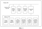
- FIG. 3 is a schematic diagram of a vehicle 300.
- the vehicle 300 includes at least the following components: a brake system 201, a power system 202, a sensing system 203, and a controller 204.
- Data obtained by the sensing system 203 is sent to the controller 204 through a vehicle CAN bus 206.
- the controller 204 operates, based on the obtained data, a program running on the memory 205, and applies obtained processing data to the vehicle 300, to control the brake system 201 and the power system 202 of the vehicle 300.
- a power system model 1, a braking system model 2, a first damping factor model 3, a second damping factor model 4, a third damping factor model 5, and a fourth damping factor model 6 are stored in the memory 205.
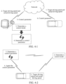
- FIG. 4-1 is a schematic architectural diagram of a vehicle control method according to an embodiment of this application.
- a vehicle terminal stores an application program for implementing vehicle control.
- For the application program stored in the vehicle terminal refer to the application program stored in the application layer of the vehicle terminal 100 shown in FIG. 2 .
- the vehicle terminal obtains a target driving speed and an actual driving speed of the vehicle through a network server; determines, based on a comparison between the target driving speed and the actual driving speed, a control mode among candidate braking control mode, acceleration control mode and stopping control mode; and determines, based on a throttle amount and braking amount determining manner corresponding to the control mode, a throttle amount and a braking amount required for implementing the target driving speed.
- the network server controls autonomous driving of the vehicle according to the throttle amount and the braking amount.
- FIG. 4-2 is a schematic architectural diagram of vehicle control according to an embodiment of this application.
- An application program for implementing vehicle control is stored in a vehicle.
- For the application program stored in the vehicle refer to the application program stored in the memory 205 of the vehicle 300 shown in FIG. 3 .
- the vehicle obtains a target driving speed and an actual driving speed of the vehicle; determines, by using the stored application program and based on a comparison between the target driving speed and the actual driving speed, a control mode among candidate braking control mode, acceleration control mode, and stopping control mode; determines, based on a throttle amount and braking amount determining manner corresponding to the control mode, a throttle amount and a braking amount required for implementing the target driving speed; and applying the determined throttle amount and braking amount to the vehicle based on the throttle amount and braking amount application manner corresponding to the control mode, so that the vehicle drives autonomously based on the throttle amount and the braking amount.
- FIG. 4-3 is a schematic architectural diagram of a vehicle control method according to an embodiment of this application.
- An application program for implementing vehicle control is stored in a vehicle terminal.
- For the application program stored in the vehicle terminal refer to the application program stored in the application layer of the vehicle terminal 100 shown in FIG. 2 .
- the vehicle terminal obtains a target driving speed and an actual driving speed of the vehicle from the vehicle by means of wireless communication, such as Bluetooth, near-field communication, and a universal serial bus (USB); determines, based on a comparison between the target driving speed and the actual driving speed, a control mode among candidate braking control mode, acceleration control mode, and stopping control mode; and determines, based on a throttle amount and braking amount determining manner corresponding to the control mode, a throttle amount and a braking amount required for implementing the target driving speed.
- the vehicle terminal controls autonomous driving of the vehicle based on the determined throttle amount and braking amount by means of wireless communication.
- the vehicle control apparatus (the vehicle terminal or vehicle) in the embodiments of this application has been described based on functions thereof.
- a vehicle control solution provided in the embodiments of this application is further described based on the schematic diagram of a functional structure of a vehicle terminal shown in FIG. 2 and a vehicle structure shown in FIG. 3 .
- FIG. 5 is a schematic flowchart of a vehicle control method according to an embodiment of this application, which is described based on steps.
- Step S101 Obtain a target driving speed and an actual driving speed of a vehicle.
- a road section is obtained based on a route planning algorithm of autonomous driving. Based on a road section from an actual location of the vehicle to a target location, a speed-time curve (that is, an acceleration curve) is applied, to obtain time and speeds corresponding to arrival at different locations in the road section that are in front of the vehicle.
- a track from the current location to a nearest sampling point in front in the route is a road section where the vehicle is currently located.
- FIG. 6 is a schematic diagram of tracks for vehicle autonomous driving according to an embodiment of this application.
- FIG. 6 shows different tracks for vehicle autonomous driving. The tracks are filtered according to multiple factors such as dynamic constraints and obstacle avoidance.
- An optimal track to the target location is selected with reference to factors such as safety, comfort, and time. In the optimal track, a speed corresponding to a front location of the different locations that is adjacent to the actual location of the vehicle is the target driving speed.
- sampling data such as an actual driving speed, an acceleration, and a vehicle posture
- sampling data is acquired by using sensors disposed in the vehicle, for example, a speed sensor, an acceleration sensor, and a vehicle body sensor.
- the acquired sampling data is filtered, to remove obvious incorrect data such as noise, so as to obtain actual running parameters of the vehicle in the road section, including an actual driving speed, an actual acceleration, and the like.
- the actual driving speed of the vehicle is measured in real time by means of satellite positioning, or the like.
- Step S 102 Determine, based on a comparison between the target driving speed and the actual driving speed, a control mode among candidate control modes.
- the candidate control modes include an acceleration control mode, a braking control mode, and a stopping control mode. Based on the comparison between the target driving speed and the actual driving speed, a control mode corresponding to the comparison result can be determined among the three candidate control modes.
- the acceleration control mode may be a method for making the actual driving speed equal to the target driving speed by using the throttle amount as the only control factor.
- the acceleration control mode may also be a method for making the actual driving speed equal to the target driving speed by using multiple control factors such as a throttle amount and a braking amount, where the throttle amount is a control factor with the highest weight among the multiple control factors.
- the braking control mode may be method for making the actual driving speed equal to the target driving speed by using the braking amount as the only control factor.
- the braking control mode may also be a method for making the actual driving speed equal to the target driving speed by using multiple control factors such as a throttle amount and a braking amount, where the braking amount is a control factor with the highest weight among the multiple control factors.
- a control mode of the vehicle can be determined quickly by comparing the target driving speed with the actual driving speed.
- the implementation process in this embodiment is simpler.
- Step S103 Determine, based on a throttle amount and braking amount determining manner corresponding to the determined control mode, a throttle amount and a braking amount required for implementing the target driving speed
- a target acceleration required for implementing the target driving speed in the road section where the vehicle is located is determined first.
- the determined target acceleration it can be implemented that the actual driving speed is equal to the target driving speed when the vehicle reaches the end of the road section.
- the determined target acceleration it is also possible to implement that the actual driving speed is equal to the target driving speed before the vehicle reaches the end of the road section, and the vehicle runs at the target driving speed constantly before reaching the end of the road section.
- a first throttle amount required for implementing the target acceleration in the road section is determined, and the first throttle amount is used as a control parameter of the vehicle.
- the power system model is a linear relationship between given throttle amounts and different accelerations that the vehicle can be driven to implement, where the relationship is obtained according to performance of components (including an internal combustion engine, a clutch, a gearbox, a differential, a throttle valve, and a throttle opening) of a power system of the vehicle.
- components including an internal combustion engine, a clutch, a gearbox, a differential, a throttle valve, and a throttle opening.
- the power system model includes at least two interconnected linear relationships. For the same vehicle, according to different gears of the vehicle, linear relationships between throttle amounts and different accelerations that the vehicle can be driven to implement are also different. As shown in FIG.
- the linear relationship between given throttle amounts and different accelerations that the vehicle can be driven to implement may not have the piecewise attribute, that is, the linear relationship between throttle amounts and different accelerations that the vehicle can be driven to implement is a continuous linear relationship.
- the second damping factor model includes a linear relationship between resistances and minimum braking amounts for implementing a moment balance state.
- the resistances at least include a wind resistance a road grade.
- the wind resistance is positively correlated to the driving speed of the vehicle, and a road down-grade is positively correlated to the braking amount, as shown in the following formula (1) and formula (2):
- Fw represents a wind resistance
- w_gain is a wind resistance coefficient
- v represents a driving speed of a vehicle
- P represents a road grade
- Km represents a grade coefficient
- a represents acceleration integration; and according to different vehicles, w_gain and Km have different values.
- an implementation process for determining the braking amount of the vehicle in the road section is the same as the implementation process for determining the braking amount of the vehicle in the road section in the foregoing embodiment.
- the difference lies in that, after the first throttle amount is determined based on the power system model, based on a first damping factor model that represents a second linear relationship between resistance offsets of the vehicle and required throttle amounts, a second throttle amount required for offsetting a resistance during driving of the vehicle is determined.
- a sum of the first throttle amount and the second throttle amount is determined.
- the control parameter is updated by using the sum of the first throttle amount and the second throttle amount. That is, the sum of the first throttle amount and the second throttle amount is used as a throttle amount for controlling the vehicle.
- Resistances related to the first damping factor model at least include a wind resistance, a mechanical friction resistance, and a road resistance.
- the mechanical friction resistance is related to a gear value of the vehicle; the road resistance is related to a gear value of the vehicle, a vehicle weight, and a road grade, as shown in the following formula (3) and formula (4):
- Ff g _ gain / N
- Fr r _ gain ⁇ N ⁇ mg ⁇ P
- Ff represents a mechanical friction resistance
- g_gain is a mechanical friction resistance coefficient
- N represents a gear value of a vehicle
- P represents a road grade
- Fr represents a road resistance
- r_gain is a road resistance coefficient
- m represents a vehicle mass
- g represents a gravitational acceleration; and according to different vehicles, r_gain and g_gain have different values.
- a sum of the first throttle amount and the second throttle amount is used as one of control parameters of the vehicle in the road section.
- the braking amount applied in the vehicle is first reduced, until the braking amount reaches the minimum braking amount to maintain the moment balance of the vehicle. Then, the throttle amount (the first throttle amount, or the sum of the first throttle amount and the second throttle amount) required for implementing the target acceleration in the road section is applied in the vehicle, until the vehicle is accelerated to the target driving speed.
- a target acceleration required for implementing the target driving speed in the road section where the vehicle is located is determined. Because the target driving speed is less than the actual driving speed, the target acceleration is a negative value. The target acceleration is in a direction opposite to that of the actual driving speed, and is also referred to as a deceleration.
- the determined target acceleration it can be implemented that the actual driving speed is equal to the target driving speed when the vehicle reaches the end of the road section.
- the determined target acceleration it is also possible to implement that the actual driving speed is equal to the target driving speed before the vehicle reaches the end of the road section, and the vehicle runs at the target driving speed constantly before reaching the end of the road section. Then, based on a braking system model that represents a fourth linear relationship between different given braking amounts of the vehicle and accelerations implemented by the vehicle, a first braking amount required for implementing the target acceleration in the road section is determined as one of control parameters.
- a braking system model is a linear relationship between given braking amounts and different accelerations that the vehicle can be controlled to implement, where the relationship is obtained according to performance of components (including: a brake pedal, a brake assist system, a brake hydraulic circuit, a brake pad, and a brake disc) of a brake system of the vehicle.
- each braking system model corresponds to a starting speed.
- accelerations obtained through the same braking amount are positively correlated to starting speeds of the corresponding braking system models.
- a linear relationship between braking amounts and accelerations shown in FIG. 9-1 corresponds to a starting speed V1
- a linear relationship between braking amounts and accelerations shown in FIG. 9-2 corresponds to a starting speed V2, where V1 is greater than V2.
- an acceleration value implemented by using the linear relationship between braking amounts and accelerations shown in FIG. 9-1 is less than an acceleration value implemented by using the linear relationship between braking amounts and accelerations shown in FIG. 9-2 .
- a braking system model needs to be determined from multiple candidate braking system models, so as to determine, by using the determined braking system model, a first braking amount required for implementing the target acceleration in the road section where the vehicle is located.
- the determined minimum braking amount is used as one of control parameters of the vehicle in the road section.
- the actual driving speed of the vehicle may be matched with the starting speed corresponding to the candidate braking system model.
- the actual driving speed is the same as the starting speed of the candidate braking system model, it is confirmed that the actual driving speed matches the starting speed corresponding to the candidate braking system model.
- a difference between the actual driving speed and the starting speed of the candidate braking system model is less than a preset threshold, it is confirmed that the actual driving speed matches the starting speed corresponding to the candidate braking system model.
- the actual driving speed is in a starting speed interval of the candidate braking system model, it is confirmed that the actual driving speed matches the starting speed corresponding to the candidate braking system model.
- the braking system model corresponding to the actual driving speed may be trained through machine training according to sample data of a vehicle of the same type. For example, braking amount data of the vehicle of the same type based on different driving speeds is used as training samples. The braking system model is trained based on the training samples and target states (accelerations) labeled by the training samples, so that the braking system model is capable of predicting a corresponding target state (acceleration) according to a training sample (braking amount).
- a relationship between resistances and minimum throttle amounts required for keeping maintaining may be fit into a linear relationship.
- a minimum throttle amount required for keeping the vehicle idling is determined according to a resistance of the vehicle during actual driving. The determined minimum throttle amount is used as one of control parameters of the vehicle in the road section.
- the resistances at least include a wind resistance and a road grade. The wind resistance is positively correlated to a driving speed of the vehicle, and a road down-grade is positively correlated to a braking amount, as shown in the foregoing formula (1) and formula (2).
- an implementation process for determining the throttle amount of the vehicle in the road section is the same as the implementation process for determining the throttle amount of the vehicle in the road section in the foregoing embodiment.
- the difference lies in that, after the first braking amount is determined based on the braking system model, based on a third damping factor model that represents a fifth linear relationship between resistances and braking amounts equivalent to the resistances, a second braking amount equivalent to a resistance that the vehicle encounters during driving and required for controlling the vehicle to keep the target driving speed is determined.
- the control parameter is updated based on a difference between the first braking amount and the second braking amount.
- Resistances related to the third damping factor model at least include a wind resistance, a mechanical friction resistance, and a road resistance.
- the mechanical friction resistance is related to a gear value of the vehicle;
- the road resistance is related to a gear value of the vehicle, a vehicle weight, and a road grade, as shown in the foregoing formula (3) and formula (4).
- second braking amount Bs ⁇ Fw + Ff + Fr where the value of Bs varies according to different vehicles.
- the second braking amount After the second braking amount is determined, after a difference between the first braking amount and the second braking amount is used as one of control parameters of the vehicle in the road section. In this way, after the first braking amount is determined, the second braking amount equivalent to the resistance that the vehicle encounters during driving is eliminated from the first braking amount, to further ensure the accuracy of deceleration.
- a throttle amount applied in the vehicle is reduced to the minimum throttle amount for keeping the vehicle decelerating.
- a braking amount required for implementing the target acceleration in the road section is applied in the vehicle, until the vehicle is decelerated to the target driving speed.
- the required braking amount is the first braking amount required for implementing the target acceleration in the road section, or a difference between the first braking amount required for implementing the target acceleration in the road section and the second braking amount equivalent to the resistance that the vehicle encounters during driving and required for implementing the target driving speed.
- the wind resistance, mechanical friction resistance, and road resistance with large impact are reserved.
- the wind resistance, the mechanical friction resistance, and the road resistance are fit into functions related to parameters that can be measured easily, for example, speed and time, thus avoiding dependency on expensive inertia elements with complex structures in the related technology, and improving the universality, implementability, and transportability of a self-driving car.
- the braking system model and the power system model that are applied so as to control the self-driving car both control the self-driving car based on both the throttle amount and the braking amount, thus avoiding vehicle vibrations (such as sudden braking or fierce braking) due to frequent switching between the brake and the throttle, and improving smoothness of speed control.
- a target acceleration required for implementing zero speed in the road section where the vehicle is located is determined. Based on a braking system model that represents a linear relationship between given braking amounts of the vehicle and accelerations implemented by the vehicle, a braking amount required for implementing the zero speed in the road section where the vehicle is located is determined. A braking amount for keeping a stopping state at the zero speed is determined.
- a specific implementation process for determining the target acceleration and the braking amount is the same as the specific implementation process for determining the target acceleration and the first braking amount in the braking control mode. The difference lies in that, the determined braking amount for keeping the stopping state at the zero speed may be a maximum braking amount that the vehicle can implement, or a predetermined ratio less than the maximum braking amount (for example, 80% of the maximum braking amount).
- the self-driving car in the stopping control mode, is controlled by using the braking system model, so that the target speed of the self-driving car is zero, thus greatly improving the smoothness of speed control.
- the vehicle is controlled by using a braking amount exceeding a particular threshold, so as to keep the stopping state and prevent the vehicle from slipping.
- the throttle amount and the braking amount are calculated by using separate algorithms. Compared with the related technology in which the throttle amount and the braking amount are calculated by using the same algorithm merely according to a difference between the current driving speed and the target driving speed, subdivision of algorithms further ensures the smooth control over the vehicle speed.
- the vehicle control method is implemented by using vehicle control models.
- the vehicle control models include: a power system model, a braking system model, a stopping system model, a first damping factor model, a second damping factor model, a third damping factor model, and a fourth damping factor model.
- the method is implemented without relying on an ESP system. Therefore, during vehicle control in this embodiment of this application, the vehicle does not need to be configured with devices such as a steering sensor, a wheel sensor, a sideslip sensor, and a transverse acceleration sensor required by the ESP system. Compared with the vehicle control method in the related technology, the vehicle control method in this embodiment of this application has lower implementation costs and better transportability.
- Step S104 Apply the determined throttle amount and braking amount to the vehicle based on a throttle amount and braking amount application manner corresponding to the determined control mode.
- integration is performed on a difference between an actual acceleration, which is obtained by applying the control parameter determined in step S103 to the vehicle, and a target acceleration that needs to be obtained according to the power control mode, the braking control mode, or the stopping control mode, to obtain a corrected value of the control parameter applied to the vehicle.
- the control parameter applied to the vehicle is updated based on the corrected value.
- FIG. 10 after a sensor acquires the actual acceleration of the vehicle, a difference between the actual acceleration and the target acceleration is calculated, and the difference is integrated by using an integrator, to obtain a corrected value of the control parameter applied to the vehicle.
- An executor updates, based on the corrected value, the control parameter applied to the vehicle.
- the braking amount applied in the vehicle is reduced based on a predetermined amplitude.
- a throttle amount (the first throttle amount, or the sum of the first throttle amount and the second throttle amount) required for implementing a target acceleration corresponding to the control mode is applied in the vehicle, until the actual driving speed is increased to the target driving speed.
- the throttle amount applied in the vehicle is reduced based on a predetermined amplitude.
- a braking amount (the first braking amount, or the difference between the first braking amount and the second braking amount) required for reaching a target acceleration corresponding to the control mode is applied in the vehicle until the actual driving speed is reduced to the target driving speed.
- a braking amount required for reaching a target acceleration corresponding to the control mode is applied in the vehicle, so that the vehicle is decelerated to the zero speed.
- a braking amount required for keeping a stopping state is applied in the vehicle, so that the vehicle keeps the stopping state, and the vehicle is prevented from slipping.
- the acceleration control mode and the braking control mode included in the control modes both control the vehicle with reference to two control factors: the throttle amount and the braking amount.
- this embodiment avoids vehicle vibrations generated due to frequent switching between the brake and the throttle, and improves the smoothness of speed control.
- the vehicle control method provided in this embodiment of this application is implemented without relying on the ESP system.
- the vehicle does not need to be configured with devices such as the steering sensor, the wheel sensor, the sideslip sensor, and the transverse acceleration sensor required by the ESP system.
- the vehicle control method in this embodiment has lower implementation costs and better transportability.
- the control mode of the vehicle can be determined quickly by comparing the target driving speed with the actual driving speed.
- the vehicle control mode is determined comprehensively according to the throttle control amount, the brake control amount, and the speed difference, the implementation process in this embodiment is simpler.
- the throttle amount and the braking amount are calculated by using separate algorithms. Compared with the related technology in which the throttle amount and the braking amount are calculated by using the same algorithm merely according to a difference between the current driving speed and the target driving speed, subdivision of algorithms further ensures the smooth control over the vehicle speed.
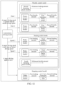
- FIG. 11 is another schematic flowchart of a vehicle control method according to an embodiment of this application. With reference to the schematic diagram of application of a vehicle control model shown in FIG. 12 , steps are described separately.
- Step A Obtain target speed information in a bus.
- Step B Filter vehicle body state information acquired by a vehicle body sensor and then return the filtered information to a controller of a vehicle.
- the vehicle body state information acquired by the vehicle body sensor includes: a speed, an acceleration, a vehicle body posture, and other information. Filtering refers to removing obvious incorrect data such as noise.
- the power system model, the braking system model, and the damping factor models are applied to the controller and are integrated with the vehicle body state information, to form a complete vehicle control model.
- Step C Determine a stopping mode class, that is, determine whether it is a stopping control mode or a running control mode.
- the running control mode includes: a braking control mode and an acceleration control mode.
- Step D Determine whether a vehicle control result reaches an expectation; if yes, end the current vehicle control process; otherwise, perform step F.
- Step E Enter the stopping control mode; based on the stopping control mode, use a comfortable deceleration manner according to a current vehicle status, until the actual driving speed is reduced to 0; and then lock a stopping state according to a current road condition, to prevent slipping.
- a braking amount for keeping the stopping state locked is a maximum braking amount that the vehicle can implement, or a predetermined ratio of braking amount less than the maximum braking amount that the vehicle can implement.
- Step F Compare a target driving speed with an actual driving speed; if the target driving speed is greater than the actual driving speed, perform step G; if the target driving speed is less than the actual driving speed, perform step H.
- Step G Control the vehicle by using the braking control mode.
- a minimum throttle amount for keeping a moment balance of the vehicle is determined first.
- the minimum throttle amount may be determined based on a fourth damping factor model that represents a sixth linear relationship between resistances and minimum throttle amounts.
- a first braking amount required for implementing a target acceleration in a road section where the vehicle is located is determined.
- the first braking amount and the minimum throttle amount are used as control parameters.
- a second braking amount required for controlling the vehicle to keep the target driving speed is determined.
- a sum of the first throttle amount and the second throttle amount, and the minimum braking amount are used as updated control parameters.
- a difference between the first braking amount and the second braking amount, and the minimum throttle amount are used as updated control parameters.
- the actual vehicle speed is converged to the target vehicle speed at an integration rate, thus achieving the objective of quickly tracking the target vehicle speed.
- Step H Control the vehicle by using the acceleration control mode.
- a minimum braking amount for keeping a moment balance of the vehicle is determined first.
- the minimum braking amount may be determined based on a second damping factor model that represents a third linear relationship between resistances and minimum braking amounts.
- a first throttle amount required for implementing a target acceleration in a road section where the vehicle is located is determined.
- the first throttle amount and the minimum braking amount are used as control parameters.
- a second throttle amount required for controlling the vehicle to keep the target driving speed is determined.
- a sum of the first throttle amount and the second throttle amount, and the minimum braking amount are used as updated control parameters. In this process, the actual vehicle speed is converged to the target vehicle speed at an integration rate, thus achieving the objective of quickly tracking the target vehicle speed.
- composition structure of a vehicle control apparatus for implementing the vehicle control method may include the following functional units: Functions of the units are described in the following.
- An obtaining unit 10 is configured to obtain a target driving speed and an actual driving speed of a vehicle in a road section where the vehicle is located.
- a control mode determining unit 20 is configured to determine, based on a comparison between the target driving speed and the actual driving speed, a control mode among candidate control modes, the candidate control modes including: a braking control mode, an acceleration control mode, and a stopping control mode.
- a control parameter determining unit 30 is configured to determine, based on a throttle amount and braking amount determining manner corresponding to the determined control mode, a throttle amount and a braking amount required for implementing the target driving speed in the road section where the vehicle is located.
- An application unit 40 is configured to apply the determined throttle amount and braking amount to the vehicle based on a throttle amount and braking amount application manner corresponding to the determined control mode.
- the obtaining unit 10 is specifically configured to apply a speed-time curve to a road section from an actual location of the vehicle to a target location, to obtain time and speeds corresponding to arrival at different locations in the road section that are in front of the vehicle; and determine a speed corresponding to a front location of the different locations that is adjacent to the actual location of the vehicle as the target driving speed.
- the application unit 40 is specifically configured to reduce, based on a predetermined amplitude, the braking amount applied in the vehicle, in a case that the control mode is the acceleration control mode; and apply a throttle amount required for implementing a target acceleration corresponding to the control mode in the vehicle until the actual driving speed is increased to the target driving speed, in a case that the applied braking amount is reduced to a minimum braking amount for keeping a moment balance of the vehicle.
- the application unit 40 is specifically configured to reduce, based on a predetermined amplitude, the throttle amount applied in the vehicle, in a case that the control mode is the braking control mode; and apply a braking amount required for reaching a target acceleration corresponding to the control mode in the vehicle until the actual driving speed is reduced to the target driving speed, in a case that the applied throttle amount is reduced to a minimum throttle amount for keeping the vehicle idling.
- the application unit 40 is specifically configured to apply a braking amount required for reaching a target acceleration corresponding to the control mode in the vehicle, in a case that the control mode is the stopping control mode; and apply a braking amount required for maintaining the vehicle in a stopping state, in a case that the speed is reduced to zero.
- the application unit 40 is specifically configured to apply, to the vehicle, a control parameter to be applied to the vehicle, to obtain an actual acceleration, and integrate a difference between the actual acceleration and a target acceleration obtained according to the control mode, to obtain a corrected value of the control parameter applied to the vehicle;
- control parameter determining unit 30 is specifically configured to determine a target acceleration required for implementing the target driving speed in a road section where the vehicle is located, in a case that the control mode is the acceleration control mode;
- control parameter determining unit 30 is specifically configured to, where the first linear relationship includes at least two successively connected linear relationships corresponding to different gears of the vehicle:
- control parameter determining unit 30 is specifically configured to determine, based on a third linear relationship between resistances and minimum braking amounts required for implementing a moment balance state as well as a resistance that the vehicle encounters during driving, a minimum braking amount to maintain the moment balance of the vehicle, and use the minimum braking amount as the braking amount required for implementing the target driving speed, in a case that the control mode is the acceleration control mode.
- control parameter determining unit 30 is specifically configured to determine a target acceleration required for implementing the target driving speed in a road section where the vehicle is located, in a case that the control mode is the braking control mode;
- a fourth linear relationship in which a starting speed matches the actual driving speed of the vehicle is determined, where in different candidate fourth linear relationships, accelerations obtained through the same braking amount are positively correlated to starting speeds of the corresponding fourth linear relationships.
- control parameter determining unit 30 is specifically configured to determine, based on a sixth linear relationship between resistances and minimum throttle amounts required for keeping maintaining as well as a resistance encountered during driving, a minimum throttle amount required for keeping the vehicle idling, and use the minimum throttle amount as the throttle amount required for implementing the target driving speed, in a case that the control mode is the braking control mode.
- An embodiment of this application further provides a vehicle, including:
- An embodiment of this application further provides a storage medium storing an executable program.
- the executable program when executed by a processor, performs the following operations: obtaining a target driving speed and an actual driving speed of a vehicle; determining, based on a comparison between the target driving speed and the actual driving speed, a control mode among candidate control modes, the candidate control modes including: a braking control mode, an acceleration control mode, and a stopping control mode; determining, based on a throttle amount and braking amount determining manner corresponding to the determined control mode, a throttle amount and a braking amount required for implementing the target driving speed; and applying the determined throttle amount and braking amount to the vehicle based on a throttle amount and braking amount application manner corresponding to the determined control mode.
- Multiple vehicle control models including a power system model, a braking system model, a stopping system model, a first resistance factor model, a second resistance factor model, a third resistance factor model, and a fourth resistance factor model, which are used for determining control parameters of a self-driving car and achieve the following advantages:
Landscapes
- Engineering & Computer Science (AREA)
- Automation & Control Theory (AREA)
- Transportation (AREA)
- Mechanical Engineering (AREA)
- Combustion & Propulsion (AREA)
- Chemical & Material Sciences (AREA)
- Radar, Positioning & Navigation (AREA)
- Physics & Mathematics (AREA)
- Remote Sensing (AREA)
- General Physics & Mathematics (AREA)
- Aviation & Aerospace Engineering (AREA)
- Human Computer Interaction (AREA)
- Electromagnetism (AREA)
- Control Of Driving Devices And Active Controlling Of Vehicle (AREA)
- Regulating Braking Force (AREA)
- Control Of Vehicle Engines Or Engines For Specific Uses (AREA)
Claims (14)
- Procédé de commande de véhicule, exécuté par un terminal de véhicule ou par un véhicule, le procédé comprenant:l'obtention d'une vitesse de conduite cible et d'une vitesse de conduite actuelle du véhicule (S101);la détermination, sur la base d'une comparaison entre la vitesse de conduite cible et la vitesse de conduite actuelle, d'un mode de commande parmi des modes de commande candidats (S102),les modes de commande candidats comprenant: un mode de réglage de frein, un mode de réglage d'accélération, et un mode de commande d'arrêt;la détermination, sur la base d'une manière de déterminer une quantité de régulation et une quantité de freinage correspondant au mode de commande déterminé, d'une quantité de régulation et d'une quantité de freinage nécessaires pour mettre en oeuvre la vitesse de conduite cible (S103); etl'application de la quantité de régulation déterminée et de la quantité de freinage au véhicule en fonction d'une manière d'appliquer une quantité de régulation et une quantité de freinage correspondant au mode de commande déterminé (S104),caractérisé en ce quela détermination, sur la base d'une manière de déterminer la quantité de régulation et la quantité de freinage correspondant au mode de commande déterminé, d'un quantité de régulation nécessaire pour mettre en oeuvre la vitesse de conduite cible consiste à:déterminer une accélération cible nécessaire pour mettre en oeuvre la vitesse de conduite cible dans un tronçon de route où se trouve le véhicule, dans le cas où le mode de commande est le mode de réglage d'accélération;déterminer, sur la base d'une première relation linéaire entre les quantités de régulation et des accélérations du véhicule, une première de quantité de régulation nécessaire pour mettre en oeuvre l'accélération cible dans le tronçon de route où se trouve le véhicule;déterminer, sur la base d'une seconde relation linéaire entre des décalages de résistance du véhicule et des quantités de régulation nécessaires, une seconde quantité de régulation nécessaire pour décaler une résistance pendant la conduite du véhicule; etdéterminer une somme de la première quantité de régulation et la seconde quantité de régulation, et utiliser la comme de la première quantité de régulation et la seconde quantité de régulation comme quantité de régulation nécessaire pour mettre en oeuvre la vitesse de conduite cible.
- Procédé selon la revendication 1, dans lequel l'obtention d'une vitesse de conduite cible du véhicule comprend:l'application d'une courbe vitesse/temps à un tronçon de route depuis un emplacement actuel du véhicule jusqu'à un emplacement cible, pour obtenir une heure et des vitesses correspondant à l'arrivée aux différents emplacements dans le tronçon de route qui se trouvent devant le véhicule; etla détermination d'une vitesse correspondant à un emplacement avant des différents emplacements qui est adjacent à l'emplacement actuel comme vitesse de conduite cible.
- Procédé selon la revendication 1, dans lequel l'application de la quantité de régulation déterminée et de la quantité de freinage au véhicule en fonction d'une manière d'appliquer une quantité de régulation et une quantité de freinage correspondant au mode de commande déterminé, consiste à:réduire, en fonction d'une amplitude prédéterminée, la quantité de freinage appliquée au véhicule, au cas où le mode de commande est le mode de commande d'accélération; etappliquer la quantité de régulation nécessaire pour mettre en oeuvre une accélération cible correspondant au mode de commande dans le véhicule jusqu'à ce que la vitesse de conduite actuelle atteigne la vitesse de conduite cible, au cas où la quantité de freinage appliquée soit réduite à la quantité de freinage minimum pour conserver un équilibre de couple du véhicule.
- Procédé selon la revendication 1, dans lequel l'application de la quantité de régulation déterminée et de la quantité de freinage au véhicule en fonction d'une manière d'appliquer une quantité de régulation et une quantité de freinage correspondant au mode de commande déterminé, consiste à:réduire, en fonction d'une amplitude prédéterminée, la quantité de freinage appliquée dans le véhicule, au cas où le mode de commande est le mode de commande de freinage; etappliquer la quantité de freinage nécessaire pour atteindre une décélération cible correspondant au mode de commande dans le véhicule jusqu'à ce que la vitesse de conduite actuelle soit réduite à la vitesse de conduite cible, au cas où la quantité de régulation appliquée soit réduite à la quantité de régulation minimum pour conserver la marche au ralenti du véhicule.
- Procédé selon la revendication 1, dans lequel l'application de la quantité de régulation déterminée et de la quantité de freinage au véhicule en fonction d'une manière d'appliquer une quantité de régulation et une quantité de freinage correspondant au mode de commande déterminé, consiste à:appliquer une quantité de freinage nécessaire pour atteindre une décélération cible correspondant au mode de commande dans le véhicule, au cas où le mode de commande est le mode de commande d'arrêt; etappliquer une quantité de freinage nécessaire pour maintenir le véhicule dans un état d'arrêt, au cas où la vitesse est réduite à zéro.
- Procédé selon la revendication 1, dans lequel l'application de la quantité de régulation déterminée et de la quantité de freinage au véhicule en fonction d'une manière d'appliquer une quantité de régulation et une quantité de freinage correspondant au mode de commande déterminé, consiste à:appliquer, au véhicule, un paramètre de commande devant être appliqué au véhicule, pour obtenir une accélération actuelle, et intégrer une différence entre l'accélération actuelle et une accélération cible obtenue conformément au mode de commande, pour obtenir une valeur corrigée du paramètre de commande appliqué au véhicule; etmettre à jour, sur la base de la valeur corrigée, le paramètre de commande appliqué au véhicule;dans lequel le paramètre de commande est une quantité de régulation ou une quantité de freinage.
- Procédé selon la revendication 1, dans lequel la première relation linéaire comprend au moins deux relations linéaires reliées successivement correspondant aux différents rapports du véhicule,
la détermination d'une première quantité de régulation nécessaire pour mettre en oeuvre l'accélération cible dans le tronçon de route où se trouve le véhicule, consiste à:déterminer des rapports cibles qui doivent être utilisés en séquence pour mettre en oeuvre l'accélération cible; etdéterminer, sur la base des relations linéaires dans la première relation linéaire qui correspondent aux rapports cibles, la première quantité de régulation nécessaire à chacun des rapports cibles. - Procédé selon la revendication 1, dans lequel la détermination, sur la base d'une manière de détermination de quantité de régulation et de quantité de freinage correspondant au mode de commande déterminé, d'une quantité de freinage nécessaire pour mettre en oeuvre la vitesse de conduite cible, consiste à:
déterminer, sur la base d'une troisième relation linéaire entre des résistances et des quantités de freinage minimum nécessaires pour mettre en oeuvre un équilibre de couple ainsi qu'une résistance que le véhicule rencontre pendant la conduite, une quantité de freinage minimum pour maintenir l'équilibrage de couple du véhicule, et utiliser la quantité de freinage minimum comme quantité de freinage nécessaire pour mettre en oeuvre la vitesse de conduite cible, au cas où le mode de commande est le mode de commande d'accélération. - Procédé selon la revendication 1, dans lequel la détermination, sur la base d'une manière de détermination de quantité de régulation et de quantité de freinage correspondant au mode de commande déterminé, d'une quantité de freinage nécessaire pour mettre en oeuvre la vitesse de conduite cible consiste à:déterminer une décélération cible nécessaire pour mettre en oeuvre la vitesse de conduite cible dans un tronçon de route où se trouve le véhicule, dans le cas où le mode de commande est le mode de commande de freinage;déterminer, sur la base d'une quatrième relation linéaire entre les quantités de freinage et les accélérations du véhicule, une première quantité de freinage nécessaire pour mettre en oeuvre la décélération cible dans le tronçon de route où se trouve le véhicule;déterminer, sur la base d'une cinquième relation linéaire entre des résistances et des quantités de freinage équivalentes aux résistances, une seconde quantité de freinage nécessaire pour la vitesse de conduite cible équivalente à une résistance que le véhicule rencontre pendant la conduite; etdéterminer une différence entre la première quantité de freinage et la seconde quantité de freinage, et utiliser la différente entre la première quantité de freinage et la seconde quantité de freinage comme quantité de freinage nécessaire pour mettre en oeuvre la vitesse de conduite cible.
- Procédé selon la revendication 9, comprenant en outre:la détermination, parmi les quatrièmes relations linéaires candidates, une quatrième relation linéaire dans laquelle une vitesse de départ correspond à la vitesse de conduite actuelle du véhicule, dans lequeldans différentes quatrièmes relations linéaires, des décélérations obtenues par la même quantité de freinage sont corrélées positivement aux vitesses de démarrage des quatrièmes relations linéaires correspondantes.
- Procédé selon la revendication 1, dans lequel la détermination, sur la base d'une manière de détermination de quantité de régulation et de quantité de freinage correspondant au mode de commande déterminé, d'une quantité de régulation nécessaire pour mettre en oeuvre la vitesse de conduite cible consiste à:
déterminer, sur la base d'une sixième relation linéaire entre des résistances et des quantités de freinage minimum nécessaires pour maintenir la marche au ralenti ainsi qu'une résistance rencontrée pendant la conduite, une quantité de régulation minimum pour maintenir la marche au ralenti du véhicule, et utiliser la quantité de régulation minimum comme quantité de régulation nécessaire pour mettre en oeuvre la vitesse de conduite cible, au cas où le mode de commande est le mode de commande de freinage. - Appareil de commande de véhicule, comprenant:une unité d'obtention (10), configurée pour obtenir une vitesse de conduite cible et une vitesse de conduite actuelle d'un véhicule;une unité de détermination de mode de commande (20), configurée pour déterminer, sur la base d'une comparaison entre la vitesse de conduite cible et la vitesse de conduite actuelle, un mode de commande parmi des modes de commande candidats, les modes de commande candidats comprenant: un mode de réglage de freinage, un mode de réglage d'accélération, et un mode de commande d'arrêt;une unité de détermination de paramètre de commande (30), configurée pour déterminer, sur la base d'une manière de détermination de quantité de régulation et de quantité de freinage correspondant au mode de commande déterminé, d'une quantité de régulation et d'une quantité de freinage nécessaires pour mettre en oeuvre la vitesse de conduite cible ; etune unité d'application (40), configurée pour appliquer la quantité de régulation déterminée et la quantité de freinage au véhicule en fonction d'une manière d'appliquer une quantité de régulation et une quantité de freinage correspondant au mode de commande déterminé,caractérisé en ce quel'unité de détermination de paramètre de commande (30) est en particulier configurée pour déterminer une accélération cible nécessaire pour mettre en oeuvre la vitesse de conduite cible dans un tronçon de route où se trouve le véhicule, dans le cas où le mode de commande est le mode de réglage d'accélération;pour déterminer, sur la base d'une première relation linéaire entre les quantités de régulation et des accélérations du véhicule, une première quantité de régulation nécessaire pour mettre en oeuvre l'accélération cible dans le tronçon de route où se trouve le véhicule;pour déterminer, sur la base d'une seconde relation linéaire entre des décalages de résistance du véhicule et des quantités de régulation nécessaires, une seconde quantité de régulation nécessaire pour décaler une résistance pendant la conduite du véhicule; etpour déterminer une somme de la première quantité de régulation et de la seconde quantité de régulation, et utiliser la somme de la première quantité de régulation et la seconde quantité de régulation comme quantité de régulation nécessaire pour mettre en oeuvre la vitesse de conduite cible.
- Véhicule, comprenant :
un appareil de commande de véhicule selon la revendication 12. - Support de stockage stockant un programme exécutable, le programme exécutable, lorsqu'il est exécuté par un processeur, met en oeuvre le procédé de commande de véhicule selon l'une quelconque des revendications 1 à 11.
Applications Claiming Priority (2)
| Application Number | Priority Date | Filing Date | Title |
|---|---|---|---|
| CN201710980290.4A CN108287540B (zh) | 2017-10-19 | 2017-10-19 | 车辆控制方法、装置、车辆及存储介质 |
| PCT/CN2018/109697 WO2019076222A1 (fr) | 2017-10-19 | 2018-10-10 | Procédé et dispositif de commande de véhicule, et véhicule support de stockage |
Publications (3)
| Publication Number | Publication Date |
|---|---|
| EP3614224A1 EP3614224A1 (fr) | 2020-02-26 |
| EP3614224A4 EP3614224A4 (fr) | 2021-01-27 |
| EP3614224B1 true EP3614224B1 (fr) | 2024-01-10 |
Family
ID=62831692
Family Applications (1)
| Application Number | Title | Priority Date | Filing Date |
|---|---|---|---|
| EP18869117.4A Active EP3614224B1 (fr) | 2017-10-19 | 2018-10-10 | Procédé et dispositif de commande de véhicule, et véhicule support de stockage |
Country Status (4)
| Country | Link |
|---|---|
| US (1) | US11214252B2 (fr) |
| EP (1) | EP3614224B1 (fr) |
| CN (1) | CN108287540B (fr) |
| WO (1) | WO2019076222A1 (fr) |
Families Citing this family (29)
| Publication number | Priority date | Publication date | Assignee | Title |
|---|---|---|---|---|
| CN108287540B (zh) | 2017-10-19 | 2020-05-08 | 腾讯科技(深圳)有限公司 | 车辆控制方法、装置、车辆及存储介质 |
| CN110967991B (zh) * | 2018-09-30 | 2023-05-26 | 百度(美国)有限责任公司 | 车辆控制参数的确定方法、装置、车载控制器和无人车 |
| CN110968088B (zh) * | 2018-09-30 | 2023-09-12 | 百度(美国)有限责任公司 | 车辆控制参数的确定方法、装置、车载控制器和无人车 |
| CN109435952A (zh) * | 2018-10-31 | 2019-03-08 | 北京新能源汽车股份有限公司 | 车辆纵向控制标定方法、装置、系统及汽车 |
| CN109747652B (zh) * | 2018-12-27 | 2021-02-19 | 东软睿驰汽车技术(沈阳)有限公司 | 一种车辆控制方法、装置及系统 |
| CN109747651B (zh) * | 2018-12-27 | 2021-08-06 | 东软睿驰汽车技术(沈阳)有限公司 | 一种车辆控制方法、装置及系统 |
| CN109895627B (zh) * | 2019-02-25 | 2020-07-31 | 武汉理工大学 | 一种汽车油门踏板和汽车油门自动控制系统 |
| CN110059095B (zh) * | 2019-03-12 | 2021-06-25 | 北京小马慧行科技有限公司 | 一种数据更新方法及装置 |
| CN109976385A (zh) * | 2019-04-03 | 2019-07-05 | 成都永奉科技有限公司 | 一种基于加速度的跟随车控制方法 |
| CN110126760B (zh) * | 2019-04-10 | 2021-07-16 | 百度在线网络技术(北京)有限公司 | 用于交通工具的驾驶控制的方法、装置、设备和介质 |
| CN110103709B (zh) * | 2019-05-20 | 2021-04-23 | 北京易控智驾科技有限公司 | 一种车辆踏板开度的控制方法、系统、设备和介质 |
| CN110164124B (zh) * | 2019-06-17 | 2021-07-27 | 吉林大学 | 一种高速公路重型卡车队列行驶中车辆纵向跟随控制方法 |
| CN112389428B (zh) * | 2019-08-02 | 2022-07-15 | 北京地平线机器人技术研发有限公司 | 车辆速度的控制方法和装置、存储介质、电子设备 |
| CN110775059B (zh) * | 2019-10-22 | 2021-08-27 | 腾讯科技(深圳)有限公司 | 一种基于人工智能的自动跟车方法和相关装置 |
| CN110962597B (zh) * | 2019-12-20 | 2021-09-24 | 重庆长安工业(集团)有限责任公司深圳分公司 | 基于车速的油门提示方法及相关装置 |
| CN111231962B (zh) * | 2020-03-03 | 2021-10-12 | 北京百度网讯科技有限公司 | 一种无人车车辆控制方法、装置、设备、车辆及介质 |
| CN111540079A (zh) * | 2020-04-02 | 2020-08-14 | 东软睿驰汽车技术(沈阳)有限公司 | 行驶状态的评价方法、装置、电子设备及存储介质 |
| CN113799772B (zh) * | 2020-09-18 | 2024-03-01 | 北京京东乾石科技有限公司 | 车辆的控制方法、装置以及控制系统 |
| CN112379668A (zh) * | 2020-10-30 | 2021-02-19 | 深圳元戎启行科技有限公司 | 车辆控制数据标定方法、装置、计算机设备和存储介质 |
| CN113127489B (zh) * | 2021-04-22 | 2024-06-21 | 京东鲲鹏(江苏)科技有限公司 | 数据表更新方法和装置 |
| CN113581210B (zh) * | 2021-08-12 | 2023-01-31 | 安徽江淮汽车集团股份有限公司 | 适用于拥堵跟车工况的自动驾驶纵向运动控制方法 |
| CN115905956B (zh) * | 2022-12-02 | 2025-09-26 | 上汽大众汽车有限公司 | 一种基于低频行驶数据的加速度识别方法、识别装置、识别设备及计算机可读存储介质 |
| CN116176531A (zh) * | 2022-12-30 | 2023-05-30 | 阿波罗智联(北京)科技有限公司 | 开度调节的性能指标的确定方法、装置和存储介质 |
| CN116227042B (zh) * | 2023-05-08 | 2023-07-07 | 中汽研(天津)汽车工程研究院有限公司 | 车辆风阻系数确定方法、设备和存储介质 |
| CN116279468B (zh) * | 2023-05-08 | 2025-10-17 | 重庆长安汽车股份有限公司 | 车辆动力系统的控制方法、装置、车辆及存储介质 |
| KR20250007871A (ko) * | 2023-07-06 | 2025-01-14 | 현대자동차주식회사 | 자율 주행 제어 장치 및 그 방법 |
| CN117332716B (zh) * | 2023-10-14 | 2024-08-20 | 兰州交通大学 | 横风环境下装配风阻制动装置高速列车制动安全速度阈值评估方法 |
| US20250383886A1 (en) * | 2024-06-14 | 2025-12-18 | Zoox, Inc. | Supervised execution of software applications on vehicle computing devices |
| CN119160185B (zh) * | 2024-08-27 | 2025-05-02 | 易显智能科技有限责任公司 | 车辆控制方法、装置及系统、以及电子设备和存储介质 |
Family Cites Families (18)
| Publication number | Priority date | Publication date | Assignee | Title |
|---|---|---|---|---|
| FR2770016B1 (fr) * | 1997-10-17 | 1999-12-10 | Renault | Procede de regulation de la distance entre deux vehicules mobiles |
| DE10229036A1 (de) * | 2002-06-28 | 2004-01-22 | Robert Bosch Gmbh | Verfahren zur Ermittlung der Masse eines Fahrzeugs |
| US7285869B2 (en) * | 2004-07-29 | 2007-10-23 | Ford Global Technologies, Llc | Method for estimating engine power in a hybrid electric vehicle powertrain |
| JP4306764B2 (ja) * | 2007-06-04 | 2009-08-05 | トヨタ自動車株式会社 | 車間距離制御装置 |
| DE102007036794B4 (de) * | 2007-08-03 | 2014-05-28 | Dr. Ing. H.C. F. Porsche Aktiengesellschaft | Verfahren zur Festlegung der Fahrstrategie eines Fahrzeuges |
| DE102011018580A1 (de) * | 2011-04-26 | 2012-10-31 | Audi Ag | Karftfahrzeug umfassend ein Fahrerassistenzsystem |
| KR101360043B1 (ko) * | 2011-12-09 | 2014-02-24 | 현대자동차주식회사 | 차속 제어 시스템 및 그 방법 |
| GB2498929B (en) * | 2012-01-25 | 2014-05-07 | Jaguar Land Rover Ltd | Adaptive control of internal combustion engine |
| WO2014006770A1 (fr) * | 2012-07-06 | 2014-01-09 | 本田技研工業株式会社 | Appareil de commande de déplacement de véhicule |
| US9682705B2 (en) * | 2015-08-13 | 2017-06-20 | Ford Global Technologies, Llc | Vehicle having ACC stop and go with braking auto-hold to increase engine autostop availability |
| CN105711441B (zh) * | 2016-01-20 | 2018-09-21 | 奇瑞汽车股份有限公司 | 车速控制方法及系统 |
| JP6418187B2 (ja) * | 2016-03-22 | 2018-11-07 | トヨタ自動車株式会社 | 車両の変速制御装置 |
| CN105818686A (zh) * | 2016-03-25 | 2016-08-03 | 北京新能源汽车股份有限公司 | 车辆的智能驾驶控制方法和控制系统 |
| JP6460349B2 (ja) * | 2016-04-13 | 2019-01-30 | トヨタ自動車株式会社 | 車両走行制御装置 |
| CN106904098B (zh) * | 2017-02-13 | 2019-04-12 | 江西江铃集团新能源汽车有限公司 | 车速控制方法及系统 |
| CN107215334B (zh) * | 2017-06-26 | 2019-12-03 | 地壳机器人科技有限公司 | 车速控制方法、装置及无人驾驶汽车 |
| US10935982B2 (en) * | 2017-10-04 | 2021-03-02 | Huawei Technologies Co., Ltd. | Method of selection of an action for an object using a neural network |
| CN108287540B (zh) * | 2017-10-19 | 2020-05-08 | 腾讯科技(深圳)有限公司 | 车辆控制方法、装置、车辆及存储介质 |
-
2017
- 2017-10-19 CN CN201710980290.4A patent/CN108287540B/zh active Active
-
2018
- 2018-10-10 EP EP18869117.4A patent/EP3614224B1/fr active Active
- 2018-10-10 WO PCT/CN2018/109697 patent/WO2019076222A1/fr not_active Ceased
-
2019
- 2019-10-01 US US16/589,251 patent/US11214252B2/en active Active
Also Published As
| Publication number | Publication date |
|---|---|
| CN108287540B (zh) | 2020-05-08 |
| WO2019076222A1 (fr) | 2019-04-25 |
| EP3614224A4 (fr) | 2021-01-27 |
| US11214252B2 (en) | 2022-01-04 |
| US20200031348A1 (en) | 2020-01-30 |
| CN108287540A (zh) | 2018-07-17 |
| EP3614224A1 (fr) | 2020-02-26 |
Similar Documents
| Publication | Publication Date | Title |
|---|---|---|
| US11214252B2 (en) | Vehicle control method and apparatus, vehicle, and storage medium | |
| US12403895B2 (en) | Method and device for vehicle parking control | |
| US20210253118A1 (en) | Autonomous vehicle actuation dynamics and latency identification | |
| CN112455446B (zh) | 用于车辆控制的方法、装置、电子设备和存储介质 | |
| US10668923B2 (en) | Method for adaptively controlling a vehicle speed in a vehicle, and speed control system for carrying out the method | |
| CN106274906A (zh) | 用于求取或者评估机动车的额定轨迹的方法和装置 | |
| US9823660B2 (en) | System for distance to stop | |
| JP7546682B2 (ja) | 車両を制御する方法、コンピュータプログラム、コンピュータ可読記憶媒体及び制御装置 | |
| US20230139711A1 (en) | Method for steering a vehicle | |
| CN113613978B (zh) | 用于操作车辆的车载控制系统 | |
| CN115743298B (zh) | 一种限制自动驾驶转向方法、装置及存储介质 | |
| WO2010064645A1 (fr) | Système d’entraînement à faible consommation de carburant | |
| JP2000099890A (ja) | 車群走行制御装置 | |
| JP6250184B2 (ja) | 車両情報制御装置 | |
| KR20170118490A (ko) | 군집주행 제어 장치 및 그 방법 | |
| JP4613124B2 (ja) | ナビ協調走行制御装置 | |
| US12377878B2 (en) | Wheel torque estimation for autonomous driving | |
| JP3365064B2 (ja) | 車両用走行制御装置 | |
| US20190346846A1 (en) | Method for Determining the Accuracy of Following a Trajectory | |
| JP2005297900A (ja) | 車速制御装置 | |
| US11491982B2 (en) | Method for controlling the powertrain of a motor vehicle | |
| CN115817505A (zh) | 一种自动泊车的纵向速度控制方法、装置和车辆 | |
| JP2014189214A (ja) | 車速制御装置 | |
| US20250212148A1 (en) | Real-time gps measurement lag compensation for vehicle state estimates | |
| US20250083699A1 (en) | Offline and online compensation for control in autonomous driving |
Legal Events
| Date | Code | Title | Description |
|---|---|---|---|
| STAA | Information on the status of an ep patent application or granted ep patent |
Free format text: STATUS: THE INTERNATIONAL PUBLICATION HAS BEEN MADE |
|
| PUAI | Public reference made under article 153(3) epc to a published international application that has entered the european phase |
Free format text: ORIGINAL CODE: 0009012 |
|
| STAA | Information on the status of an ep patent application or granted ep patent |
Free format text: STATUS: REQUEST FOR EXAMINATION WAS MADE |
|
| 17P | Request for examination filed |
Effective date: 20191120 |
|
| AK | Designated contracting states |
Kind code of ref document: A1 Designated state(s): AL AT BE BG CH CY CZ DE DK EE ES FI FR GB GR HR HU IE IS IT LI LT LU LV MC MK MT NL NO PL PT RO RS SE SI SK SM TR |
|
| AX | Request for extension of the european patent |
Extension state: BA ME |
|
| A4 | Supplementary search report drawn up and despatched |
Effective date: 20210114 |
|
| DAV | Request for validation of the european patent (deleted) | ||
| DAX | Request for extension of the european patent (deleted) | ||
| RIC1 | Information provided on ipc code assigned before grant |
Ipc: B60W 30/14 20060101ALI20201223BHEP Ipc: B60W 10/14 20120101ALI20201223BHEP Ipc: B60W 10/18 20120101ALI20201223BHEP Ipc: B60W 30/17 20200101ALI20201223BHEP Ipc: B60W 10/06 20060101ALI20201223BHEP Ipc: B60W 50/00 20060101ALI20201223BHEP Ipc: G05D 1/02 20200101AFI20201223BHEP |
|
| RAP3 | Party data changed (applicant data changed or rights of an application transferred) |
Owner name: TENCENT TECHNOLOGY (SHENZHEN) COMPANY LIMITED |
|
| GRAP | Despatch of communication of intention to grant a patent |
Free format text: ORIGINAL CODE: EPIDOSNIGR1 |
|
| STAA | Information on the status of an ep patent application or granted ep patent |
Free format text: STATUS: GRANT OF PATENT IS INTENDED |
|
| INTG | Intention to grant announced |
Effective date: 20230927 |
|
| GRAS | Grant fee paid |
Free format text: ORIGINAL CODE: EPIDOSNIGR3 |
|
| GRAA | (expected) grant |
Free format text: ORIGINAL CODE: 0009210 |
|
| STAA | Information on the status of an ep patent application or granted ep patent |
Free format text: STATUS: THE PATENT HAS BEEN GRANTED |
|
| AK | Designated contracting states |
Kind code of ref document: B1 Designated state(s): AL AT BE BG CH CY CZ DE DK EE ES FI FR GB GR HR HU IE IS IT LI LT LU LV MC MK MT NL NO PL PT RO RS SE SI SK SM TR |
|
| REG | Reference to a national code |
Ref country code: GB Ref legal event code: FG4D |
|
| REG | Reference to a national code |
Ref country code: CH Ref legal event code: EP |
|
| REG | Reference to a national code |
Ref country code: DE Ref legal event code: R096 Ref document number: 602018064095 Country of ref document: DE |
|
| REG | Reference to a national code |
Ref country code: IE Ref legal event code: FG4D |
|
| REG | Reference to a national code |
Ref country code: LT Ref legal event code: MG9D |
|
| REG | Reference to a national code |
Ref country code: NL Ref legal event code: MP Effective date: 20240110 |
|
| REG | Reference to a national code |
Ref country code: AT Ref legal event code: MK05 Ref document number: 1649392 Country of ref document: AT Kind code of ref document: T Effective date: 20240110 |
|
| PG25 | Lapsed in a contracting state [announced via postgrant information from national office to epo] |
Ref country code: NL Free format text: LAPSE BECAUSE OF FAILURE TO SUBMIT A TRANSLATION OF THE DESCRIPTION OR TO PAY THE FEE WITHIN THE PRESCRIBED TIME-LIMIT Effective date: 20240110 |
|
| PG25 | Lapsed in a contracting state [announced via postgrant information from national office to epo] |
Ref country code: NL Free format text: LAPSE BECAUSE OF FAILURE TO SUBMIT A TRANSLATION OF THE DESCRIPTION OR TO PAY THE FEE WITHIN THE PRESCRIBED TIME-LIMIT Effective date: 20240110 |
|
| PG25 | Lapsed in a contracting state [announced via postgrant information from national office to epo] |
Ref country code: IS Free format text: LAPSE BECAUSE OF FAILURE TO SUBMIT A TRANSLATION OF THE DESCRIPTION OR TO PAY THE FEE WITHIN THE PRESCRIBED TIME-LIMIT Effective date: 20240510 |
|
| PG25 | Lapsed in a contracting state [announced via postgrant information from national office to epo] |
Ref country code: LT Free format text: LAPSE BECAUSE OF FAILURE TO SUBMIT A TRANSLATION OF THE DESCRIPTION OR TO PAY THE FEE WITHIN THE PRESCRIBED TIME-LIMIT Effective date: 20240110 |
|
| PG25 | Lapsed in a contracting state [announced via postgrant information from national office to epo] |
Ref country code: GR Free format text: LAPSE BECAUSE OF FAILURE TO SUBMIT A TRANSLATION OF THE DESCRIPTION OR TO PAY THE FEE WITHIN THE PRESCRIBED TIME-LIMIT Effective date: 20240411 |
|
| PG25 | Lapsed in a contracting state [announced via postgrant information from national office to epo] |
Ref country code: HR Free format text: LAPSE BECAUSE OF FAILURE TO SUBMIT A TRANSLATION OF THE DESCRIPTION OR TO PAY THE FEE WITHIN THE PRESCRIBED TIME-LIMIT Effective date: 20240110 Ref country code: RS Free format text: LAPSE BECAUSE OF FAILURE TO SUBMIT A TRANSLATION OF THE DESCRIPTION OR TO PAY THE FEE WITHIN THE PRESCRIBED TIME-LIMIT Effective date: 20240410 |
|
| PG25 | Lapsed in a contracting state [announced via postgrant information from national office to epo] |
Ref country code: ES Free format text: LAPSE BECAUSE OF FAILURE TO SUBMIT A TRANSLATION OF THE DESCRIPTION OR TO PAY THE FEE WITHIN THE PRESCRIBED TIME-LIMIT Effective date: 20240110 |
|
| PG25 | Lapsed in a contracting state [announced via postgrant information from national office to epo] |
Ref country code: AT Free format text: LAPSE BECAUSE OF FAILURE TO SUBMIT A TRANSLATION OF THE DESCRIPTION OR TO PAY THE FEE WITHIN THE PRESCRIBED TIME-LIMIT Effective date: 20240110 |
|
| PG25 | Lapsed in a contracting state [announced via postgrant information from national office to epo] |
Ref country code: RS Free format text: LAPSE BECAUSE OF FAILURE TO SUBMIT A TRANSLATION OF THE DESCRIPTION OR TO PAY THE FEE WITHIN THE PRESCRIBED TIME-LIMIT Effective date: 20240410 Ref country code: NO Free format text: LAPSE BECAUSE OF FAILURE TO SUBMIT A TRANSLATION OF THE DESCRIPTION OR TO PAY THE FEE WITHIN THE PRESCRIBED TIME-LIMIT Effective date: 20240410 Ref country code: LT Free format text: LAPSE BECAUSE OF FAILURE TO SUBMIT A TRANSLATION OF THE DESCRIPTION OR TO PAY THE FEE WITHIN THE PRESCRIBED TIME-LIMIT Effective date: 20240110 Ref country code: IS Free format text: LAPSE BECAUSE OF FAILURE TO SUBMIT A TRANSLATION OF THE DESCRIPTION OR TO PAY THE FEE WITHIN THE PRESCRIBED TIME-LIMIT Effective date: 20240510 Ref country code: HR Free format text: LAPSE BECAUSE OF FAILURE TO SUBMIT A TRANSLATION OF THE DESCRIPTION OR TO PAY THE FEE WITHIN THE PRESCRIBED TIME-LIMIT Effective date: 20240110 Ref country code: GR Free format text: LAPSE BECAUSE OF FAILURE TO SUBMIT A TRANSLATION OF THE DESCRIPTION OR TO PAY THE FEE WITHIN THE PRESCRIBED TIME-LIMIT Effective date: 20240411 Ref country code: ES Free format text: LAPSE BECAUSE OF FAILURE TO SUBMIT A TRANSLATION OF THE DESCRIPTION OR TO PAY THE FEE WITHIN THE PRESCRIBED TIME-LIMIT Effective date: 20240110 Ref country code: BG Free format text: LAPSE BECAUSE OF FAILURE TO SUBMIT A TRANSLATION OF THE DESCRIPTION OR TO PAY THE FEE WITHIN THE PRESCRIBED TIME-LIMIT Effective date: 20240110 Ref country code: AT Free format text: LAPSE BECAUSE OF FAILURE TO SUBMIT A TRANSLATION OF THE DESCRIPTION OR TO PAY THE FEE WITHIN THE PRESCRIBED TIME-LIMIT Effective date: 20240110 |
|
| PG25 | Lapsed in a contracting state [announced via postgrant information from national office to epo] |
Ref country code: PL Free format text: LAPSE BECAUSE OF FAILURE TO SUBMIT A TRANSLATION OF THE DESCRIPTION OR TO PAY THE FEE WITHIN THE PRESCRIBED TIME-LIMIT Effective date: 20240110 Ref country code: PT Free format text: LAPSE BECAUSE OF FAILURE TO SUBMIT A TRANSLATION OF THE DESCRIPTION OR TO PAY THE FEE WITHIN THE PRESCRIBED TIME-LIMIT Effective date: 20240510 |
|
| PG25 | Lapsed in a contracting state [announced via postgrant information from national office to epo] |
Ref country code: SE Free format text: LAPSE BECAUSE OF FAILURE TO SUBMIT A TRANSLATION OF THE DESCRIPTION OR TO PAY THE FEE WITHIN THE PRESCRIBED TIME-LIMIT Effective date: 20240110 Ref country code: PT Free format text: LAPSE BECAUSE OF FAILURE TO SUBMIT A TRANSLATION OF THE DESCRIPTION OR TO PAY THE FEE WITHIN THE PRESCRIBED TIME-LIMIT Effective date: 20240510 Ref country code: PL Free format text: LAPSE BECAUSE OF FAILURE TO SUBMIT A TRANSLATION OF THE DESCRIPTION OR TO PAY THE FEE WITHIN THE PRESCRIBED TIME-LIMIT Effective date: 20240110 Ref country code: LV Free format text: LAPSE BECAUSE OF FAILURE TO SUBMIT A TRANSLATION OF THE DESCRIPTION OR TO PAY THE FEE WITHIN THE PRESCRIBED TIME-LIMIT Effective date: 20240110 |
|
| PG25 | Lapsed in a contracting state [announced via postgrant information from national office to epo] |
Ref country code: DK Free format text: LAPSE BECAUSE OF FAILURE TO SUBMIT A TRANSLATION OF THE DESCRIPTION OR TO PAY THE FEE WITHIN THE PRESCRIBED TIME-LIMIT Effective date: 20240110 |
|
| REG | Reference to a national code |
Ref country code: DE Ref legal event code: R097 Ref document number: 602018064095 Country of ref document: DE |
|
| PG25 | Lapsed in a contracting state [announced via postgrant information from national office to epo] |
Ref country code: SM Free format text: LAPSE BECAUSE OF FAILURE TO SUBMIT A TRANSLATION OF THE DESCRIPTION OR TO PAY THE FEE WITHIN THE PRESCRIBED TIME-LIMIT Effective date: 20240110 |
|
| PG25 | Lapsed in a contracting state [announced via postgrant information from national office to epo] |
Ref country code: EE Free format text: LAPSE BECAUSE OF FAILURE TO SUBMIT A TRANSLATION OF THE DESCRIPTION OR TO PAY THE FEE WITHIN THE PRESCRIBED TIME-LIMIT Effective date: 20240110 Ref country code: CZ Free format text: LAPSE BECAUSE OF FAILURE TO SUBMIT A TRANSLATION OF THE DESCRIPTION OR TO PAY THE FEE WITHIN THE PRESCRIBED TIME-LIMIT Effective date: 20240110 |
|
| PG25 | Lapsed in a contracting state [announced via postgrant information from national office to epo] |
Ref country code: SK Free format text: LAPSE BECAUSE OF FAILURE TO SUBMIT A TRANSLATION OF THE DESCRIPTION OR TO PAY THE FEE WITHIN THE PRESCRIBED TIME-LIMIT Effective date: 20240110 |
|
| PG25 | Lapsed in a contracting state [announced via postgrant information from national office to epo] |
Ref country code: SM Free format text: LAPSE BECAUSE OF FAILURE TO SUBMIT A TRANSLATION OF THE DESCRIPTION OR TO PAY THE FEE WITHIN THE PRESCRIBED TIME-LIMIT Effective date: 20240110 Ref country code: SK Free format text: LAPSE BECAUSE OF FAILURE TO SUBMIT A TRANSLATION OF THE DESCRIPTION OR TO PAY THE FEE WITHIN THE PRESCRIBED TIME-LIMIT Effective date: 20240110 Ref country code: RO Free format text: LAPSE BECAUSE OF FAILURE TO SUBMIT A TRANSLATION OF THE DESCRIPTION OR TO PAY THE FEE WITHIN THE PRESCRIBED TIME-LIMIT Effective date: 20240110 Ref country code: EE Free format text: LAPSE BECAUSE OF FAILURE TO SUBMIT A TRANSLATION OF THE DESCRIPTION OR TO PAY THE FEE WITHIN THE PRESCRIBED TIME-LIMIT Effective date: 20240110 Ref country code: DK Free format text: LAPSE BECAUSE OF FAILURE TO SUBMIT A TRANSLATION OF THE DESCRIPTION OR TO PAY THE FEE WITHIN THE PRESCRIBED TIME-LIMIT Effective date: 20240110 Ref country code: CZ Free format text: LAPSE BECAUSE OF FAILURE TO SUBMIT A TRANSLATION OF THE DESCRIPTION OR TO PAY THE FEE WITHIN THE PRESCRIBED TIME-LIMIT Effective date: 20240110 |
|
| PLBE | No opposition filed within time limit |
Free format text: ORIGINAL CODE: 0009261 |
|
| STAA | Information on the status of an ep patent application or granted ep patent |
Free format text: STATUS: NO OPPOSITION FILED WITHIN TIME LIMIT |
|
| PG25 | Lapsed in a contracting state [announced via postgrant information from national office to epo] |
Ref country code: IT Free format text: LAPSE BECAUSE OF FAILURE TO SUBMIT A TRANSLATION OF THE DESCRIPTION OR TO PAY THE FEE WITHIN THE PRESCRIBED TIME-LIMIT Effective date: 20240110 |
|
| 26N | No opposition filed |
Effective date: 20241011 |
|
| PG25 | Lapsed in a contracting state [announced via postgrant information from national office to epo] |
Ref country code: IT Free format text: LAPSE BECAUSE OF FAILURE TO SUBMIT A TRANSLATION OF THE DESCRIPTION OR TO PAY THE FEE WITHIN THE PRESCRIBED TIME-LIMIT Effective date: 20240110 |
|
| PG25 | Lapsed in a contracting state [announced via postgrant information from national office to epo] |
Ref country code: SI Free format text: LAPSE BECAUSE OF FAILURE TO SUBMIT A TRANSLATION OF THE DESCRIPTION OR TO PAY THE FEE WITHIN THE PRESCRIBED TIME-LIMIT Effective date: 20240110 |
|
| REG | Reference to a national code |
Ref country code: CH Ref legal event code: PL |
|
| PG25 | Lapsed in a contracting state [announced via postgrant information from national office to epo] |
Ref country code: MC Free format text: LAPSE BECAUSE OF FAILURE TO SUBMIT A TRANSLATION OF THE DESCRIPTION OR TO PAY THE FEE WITHIN THE PRESCRIBED TIME-LIMIT Effective date: 20240110 |
|
| PG25 | Lapsed in a contracting state [announced via postgrant information from national office to epo] |
Ref country code: BE Free format text: LAPSE BECAUSE OF NON-PAYMENT OF DUE FEES Effective date: 20241031 Ref country code: LU Free format text: LAPSE BECAUSE OF NON-PAYMENT OF DUE FEES Effective date: 20241010 |
|
| PG25 | Lapsed in a contracting state [announced via postgrant information from national office to epo] |
Ref country code: CH Free format text: LAPSE BECAUSE OF NON-PAYMENT OF DUE FEES Effective date: 20241031 |
|
| REG | Reference to a national code |
Ref country code: BE Ref legal event code: MM Effective date: 20241031 |
|
| PG25 | Lapsed in a contracting state [announced via postgrant information from national office to epo] |
Ref country code: FI Free format text: LAPSE BECAUSE OF FAILURE TO SUBMIT A TRANSLATION OF THE DESCRIPTION OR TO PAY THE FEE WITHIN THE PRESCRIBED TIME-LIMIT Effective date: 20240110 |
|
| PG25 | Lapsed in a contracting state [announced via postgrant information from national office to epo] |
Ref country code: IE Free format text: LAPSE BECAUSE OF NON-PAYMENT OF DUE FEES Effective date: 20241010 |
|
| PGFP | Annual fee paid to national office [announced via postgrant information from national office to epo] |
Ref country code: DE Payment date: 20251020 Year of fee payment: 8 |
|
| PGFP | Annual fee paid to national office [announced via postgrant information from national office to epo] |
Ref country code: GB Payment date: 20251024 Year of fee payment: 8 |
|
| PGFP | Annual fee paid to national office [announced via postgrant information from national office to epo] |
Ref country code: FR Payment date: 20251017 Year of fee payment: 8 |
|
| PG25 | Lapsed in a contracting state [announced via postgrant information from national office to epo] |
Ref country code: CY Free format text: LAPSE BECAUSE OF FAILURE TO SUBMIT A TRANSLATION OF THE DESCRIPTION OR TO PAY THE FEE WITHIN THE PRESCRIBED TIME-LIMIT; INVALID AB INITIO Effective date: 20181010 |
|
| PG25 | Lapsed in a contracting state [announced via postgrant information from national office to epo] |
Ref country code: HU Free format text: LAPSE BECAUSE OF FAILURE TO SUBMIT A TRANSLATION OF THE DESCRIPTION OR TO PAY THE FEE WITHIN THE PRESCRIBED TIME-LIMIT; INVALID AB INITIO Effective date: 20181010 |