EP3614341A1 - Appareil, procédé et programme informatique permettant de détecter la forme d'un objet déformable - Google Patents
Appareil, procédé et programme informatique permettant de détecter la forme d'un objet déformable Download PDFInfo
- Publication number
- EP3614341A1 EP3614341A1 EP18190587.8A EP18190587A EP3614341A1 EP 3614341 A1 EP3614341 A1 EP 3614341A1 EP 18190587 A EP18190587 A EP 18190587A EP 3614341 A1 EP3614341 A1 EP 3614341A1
- Authority
- EP
- European Patent Office
- Prior art keywords
- state
- iteration step
- drones
- pose
- drone
- Prior art date
- Legal status (The legal status is an assumption and is not a legal conclusion. Google has not performed a legal analysis and makes no representation as to the accuracy of the status listed.)
- Withdrawn
Links
Images

Classifications
-
- G—PHYSICS
- G06—COMPUTING OR CALCULATING; COUNTING
- G06T—IMAGE DATA PROCESSING OR GENERATION, IN GENERAL
- G06T7/00—Image analysis
- G06T7/50—Depth or shape recovery
- G06T7/55—Depth or shape recovery from multiple images
-
- G—PHYSICS
- G06—COMPUTING OR CALCULATING; COUNTING
- G06T—IMAGE DATA PROCESSING OR GENERATION, IN GENERAL
- G06T2207/00—Indexing scheme for image analysis or image enhancement
- G06T2207/30—Subject of image; Context of image processing
- G06T2207/30196—Human being; Person
-
- G—PHYSICS
- G06—COMPUTING OR CALCULATING; COUNTING
- G06T—IMAGE DATA PROCESSING OR GENERATION, IN GENERAL
- G06T2207/00—Indexing scheme for image analysis or image enhancement
- G06T2207/30—Subject of image; Context of image processing
- G06T2207/30244—Camera pose
Definitions
- the invention refers to the detection, estimation or determination of the form of a deformable object, e.g. the pose of a human.
- Motion Capture Motion Capture
- Many graphics applications such as character animation for games, sports, biomechanics, VR, and AR rely on accurate human pose information, and virtually every modern movie production leverages Motion Capture (Mocap) systems for special effects.
- Mocap Motion Capture
- Most commonly, such systems are camera based, either relying on body-worn markers, or more recently even work markerless.
- Multi-view approaches can now be highly accurate and sometimes provide dense surface reconstructions.
- the maturing of camera-based motion capture technology leads to a desire to use it in increasingly challenging scenarios such as with fast moving actors, large scale scenes and even in outdoors settings.
- all existing approaches require a set of environment-mounted, accurately calibrated cameras looking into a capture area of fixed size. This requirement for stationary cameras makes application in these settings very tedious, costly and sometimes entirely infeasible.
- IMUs inertial measurement units
- the detection of the movement of the plurality of IMUs results in the pose detection.
- IMU solutions have the advantage of being mobile. However, the accumulation of small detection errors could lead over longer detection periods to larger errors in the pose detection.
- IMU based solutions require user instrumentation. They also rely on sophisticated models of the human and hence cannot easily be generalized to other subjects.
- Rui Li Minjian Pang, Cong Zhao, Guyue Zhou and Lu Fang published 2016 the article "Monocular long-term target following on uavs" in Proceedings of the IEEE Conference on Computer Vision and Pattern Recognition Workshops, 29-37 . It discloses a way to recover the 3D trajectory of a moving person from one micro arial vehicle (MAV) with a camera following and filming the person. However, this does not allow to track or determine the pose of the human.
- MAV micro arial vehicle
- multi-robot teams including groups of aerial robots like MAVs.
- each agent requires exact positional knowledge.
- Existing approaches to formation flight therefore rely either on low precision sensors, which result in large inter-robot distances, or on external infrastructure.
- Methods for infrastructure-free formation control have been proposed albeit requiring the cameras to be trained on the other members of the swarm, rendering it unsuitable for subject tracking.
- the method should be infrastructure-free.
- the use of multiple drones with cameras allow to make the tracking of a moving deformable object in an infrastructure-free way.
- the drones follow the object wherever to the object moves and the multiple camera views from the drones on the object allow a tracking of the form of the object.
- the joint estimation of the three-dimensional positions of the detection points and of the parameters of the drones and/or of the cameras defining the position and orientation of the cameras (and thus the image content) allows to obtain high quality estimates of all or at least most of the parameters of the drones and/or of the cameras. This allows a very precise drone control without the necessity of highly precise drone position sensors.
- the pose state (or any other state to be determined) of the current iteration step is estimated based on the pose state (or the other state) of a previous iteration step. Preferably, this is done by a Kalman filter. This solution is very resource efficient, allows a detection in real time and is very robust and reliable.
- the pose state comprises further the orientations of each drone and/or, if the cameras are movable in the drones, the orientation of the camera of each drone with respect to the respective drone.
- the (assumed constant) distances between connected detection points of the object are used for estimating the pose state.
- a distance state comprises a set of distances defining the distances between connected detection points, wherein the distance state is estimated based on the pose state of the current or previous state and/or based on the distance state of the previous iteration step. This allows to estimate the (preferably constant, but unknown) distances between the detection points.
- a control state comprises further control parameters of the drones which do not influence the image of the camera of each drone, wherein the control state is estimated based on the control state of the previous state, wherein the control state comprises preferably the velocity of each drone, wherein the drones are further controlled based on the control state of the current iteration step.
- the pose state is estimated with a first Kalman filter and the distance state and/or control state is estimated with a second Kalman filter and/or third Kalman filter being separate from the first Kalman filter.
- the estimated distance states of the second Kalman filter is used as input for the first Kalman filter and/or the estimated pose states (at least some of them) of the first Kalman filter is used as input for the second Kalman filter.
- This approach reduces the dimension of the two and/or three Kalman filters for the pose and the distance and/or control state compared to one joint Kalman filter for a joint state including the pose and distance and/or control state. Since the computational effort of the Kalman filter is cubic with respect to the dimension, this makes the estimation computationally much more efficient. Therefore, this is very advantageous for embodiments with many detection points, many drones and/or many drone parameters.
- the pose state and the distance state and/or the control state define a joint state, wherein the joint state of the current iteration step is estimated with a Kalman filter based on the joint state of the previous iteration step.
- the origin of the detection coordinate system moves with one of the at least two drones or with a point defined by two or more of the at least two drones.
- the detection coordinate system is for example the centre of gravity of all drones.
- one of the at least two drones is defined as a lead drone and the at least one other drone is defined as at least one secondary drone, wherein the detection coordinate system corresponds to the coordinate system of the lead drone.
- the lead drone comprises a sensor for detecting the movement of the lead drone between the previous iteration step and the current iteration step.
- the pose state of the previous iteration step is corrected based on the detected movement of the lead drone to obtain a corrected pose state of the previous iteration step, wherein the pose state of the current iteration step is estimated based on the image positions of the received images of the current iteration and based on the corrected pose state of the previous iteration step.
- at least the three-dimensional positions of the secondary drones of the previous iteration step and the three-dimensional positions of the detection points are corrected in the pose state based on the detected movement of the lead drone to obtain a corrected pose state of the previous iteration step.
- the correction of at least some states which are influenced by the displacement of the lead drone by a displacement measured by a sensor (in the lead drone) allows to use iterative estimation methods based on the states of the previous iteration step.
- the covariance matrix of the pose state of the previous iteration step is corrected by the displacement covariance matrix which is based on the variance of the movement of the sensor (of the current step), wherein the pose state of the current iteration step is estimated further based on the corrected covariance matrix of the pose state of the previous iteration step.
- the displacement covariance matrix corresponds to a diagonal matrix whose diagonal entries of state dimensions which have been corrected by the displacement of the lead drone correspond to the variance of the displacement and/or whose diagonal entries of state dimensions which have not been corrected by the displacement of the lead drone correspond to zero.
- the variance of the position of the lead drone in the covariance matrix of the pose state of the previous iteration step is set to zero such that the position of the lead drone remains fixed.
- the detection points are markers attached or worn by the moving deformable object. This has the advantage that the detection of the form of the object is independent of a model of the object.
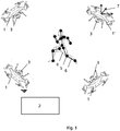
- Fig. 1 shows an embodiment of an apparatus or system for detecting the form of a moving deformable object.
- the object 4 is preferably a human, a human-like robot or an animal. However, the object can be also another deformable object 4. In the following description of an embodiment, the invention will be explained at the example of a human 4 without any limitation of the invention.
- the human 4 can be replaced by any other deformable object 4.
- the form of the object 4 is defined by a (relative) position of a plurality of detection points of the object.
- the detection points 5 are preferably markers which are applied on the object 4.
- the markers 5 can be lights (visible, ultraviolet (UV), infrared (IR) and/or in other frequency bands).
- the light can be actively emitting like a light emitting diode (LED) or be passive like a reflector.
- the lights can blink with a frequency, preferably each light blinks with a different frequency to be better detectable or identifiable.
- the marker 5 could be also a simple colour marker.
- the detection point 5 can also be detected by image recognition or other means and/or without a marker, maybe based on a model of the object.
- all detection points 5 are called markers without any limitation of the invention. Obviously, the markers can be replaced by other detection points 5.
- the detection points 5 correspond preferably to positions of joints of the object 4.
- the plurality of detection points 5 model or define the form of the object 4.
- the number of the detection points 5 is in the following abbreviated by m.
- the m detection points 5 are different from each other such that they are identifiable in an image.
- the object 4 is such that at least some, preferably each detection point 5 has at least one connected neighbouring detection point 5 with a constant distance.
- neighbouring detection points 5 or joints are connected via a bone 6 with constant length.
- all detection points 5 are connected by bones 6 without any limitation of the invention.
- the bones 6 can be replaced by other connections 6 with constant length and maybe even with variable length.
- the form of the (deformable object 4) like the human, the human like robot or the animal is also called (form) pose and describes the state of his/her/its joints. This (form) pose of the deformable object is well to be distinguished from the (position) pose of the drone referring to the position and orientation of the drone.
- the apparatus or system comprises a plurality of drones 1 and a processing apparatus 2 (which can be also called processing means or processor or processing device).
- the number of drones 1, 1' is in the following defined as n.
- the drones 1, 1' are configured to fly with a remote control (from the processing apparatus 2).
- the drones 1, 1' are preferably an MAV.
- the drones 1, 1' are preferably rotorcrafts. This allows them also to move slowly and quickly changing direction and orientation.
- each drone 1, 1' comprises a plurality of rotors (with parallel rotor axes).
- the drones 1, 1' are quadrotors, i.e. having four rotors.
- the drones 1, 1' are quadrotors without any limitation of the invention.
- the quadrotors 1, 1' can be replaced by any other type of drones 1, 1'.
- Each drone 1, 1' can be controlled as described in more detail later such to follow the moving deformable object and/or to maintain a certain distance from the other drones 1, 1'.
- the moving deformable object 4 can move in any environment described by a global coordinate system.
- the drones 1, 1' follow the object 4 in the environment or the global coordinate system.
- Each drone 1, 1' defines a drone coordinate system in which the drone 1,1' does not move.
- Each drone 1, 1' comprises a camera 3 configured to take an image (or picture) of the movable deformable object 4 and/or of the detection points 5.
- the camera 3 is preferably a digital camera, i.e. a camera with a digital image sensor recording the image projected from the environment into the camera. If the detection points 5 are markers, the camera 3 is preferably configured to record the marker points. Preferably the camera 3 is configured to record light at least in at least one light wavelength of the markers. For example, if the marker is an UV, visible or IR marker, the camera 3 should be configured to record UV, visible or IR light respectively. The camera 3 is preferably configured to record light. The camera 3 is preferably configured to record light in the visible spectrum. However, it is also possible that the camera 3 in addition or alternatively records light in other spectra. The camera 3 can also be of any other type, for example a time of flight camera.
- the camera 3 has at least one camera parameter which can be changed (by the remote control).
- the camera parameter is configured such that a change of the camera parameter causes a change of the image seen/taken by the camera 3.
- the at least one camera parameter comprises the (rotational and/or translational) camera position.
- the camera position comprises a rotational position, preferably comprising pitch and/or yaw of the camera 3 with respect to the drone coordinate system. Additionally or alternatively, the camera position can comprise a translation of the camera 3. A change of the camera position causes a change of the image seen/taken by the camera 3.
- the camera 3 is arranged in a movable fashion on the drone 1, 1' such that the camera axis of the camera 3 can be moved with respect to the drone 1, 1' and/or the drone coordinate system.
- the camera coordinate system is movable with respect to the drone coordinate system depending on the applied camera position.
- the camera 3 can be rotated (around pitch and yaw).
- the camera parameter can also comprise other parameter which change the image seen/taken by the camera 3 like the focus/zoom or others.
- the camera parameters are pitch and yaw without any limitation of the invention. Obviously, pitch and yaw can be replaced or completed by any other camera parameter.
- a pose state vector comprises preferably the camera parameter (or more exactly comprises an estimate of the camera parameter).
- Each image taken by the camera 3 is described with an image coordinate system describing the positions within the image of the camera 3 (image position).
- the image coordinate system could for example correspond to the pixel coordinates of the image.
- the image coordinate system is preferably two-dimensional and/or lies preferably in the image plane of the camera 3 in the camera coordinate system.
- the image is preferably the projection of the three-dimensional object 4 on the (two-dimensional) image plane and/or the image coordinate system.
- the camera 3 is configured to take at least one (full) image in each iteration step described later.
- the camera 3 is preferably configured to take at least 5 images per second (>5Hz), preferably at least 10 images per second (>10Hz), preferably at least 15 images per second (>15Hz), preferably at least 20 images per second (>20Hz), preferably at least 25 images per second (>25Hz).
- the drones 1, 1' comprise one lead drone 1' and at least one secondary drone 1.
- the lead drone 1' comprises displacement sensor (not shown in Fig. 1 ) for detecting the displacement of the lead drone 1' in the environment and/or in the global coordinate system.
- this sensor comprises an accelerometer (for detecting a translation of the lead drone 1'), a gyroscope (for detecting a rotation of the lead drone 1'), a magnetometer (for detecting a reference for the rotation of the lead drone 1') and/or an IMU (for detecting a translation and a rotation of the lead drone 1').
- this sensor comprises alternatively or additionally a optical flow sensor which detects the displacement of the lead drone 1' based on a drone mounted camera mounted on the lead drone 1'.
- this drone mounted camera is a camera directed to the ground, e.g. in the direction of the rotor axis.
- the displacement sensor can also comprise a position sensor which allows to determine the displacement from the difference of the positions. Obviously, all other kind of displacement sensors is possible.
- the lead drone 1' sends the determined displacement or raw data allowing to determine the displacement to the processing apparatus 2, preferably (wirelessly) to the processing device. In a less preferred embodiment, the displacement sensor can also be arranged outside of the lead drone 1'.
- the lead drone 1' comprises further a position sensor configured to detect the absolute position of the lead drone 1' with respect to the global coordinate system and/or in the environment.
- the lead drone 1' sends the determined position to the processing apparatus 2, preferably (wirelessly) to the processing device.
- a detection coordinate system corresponds to the coordinate system of the lead drone 1', i.e. the origin of detection coordinate system and of the coordinate system of the lead drone 1' are equal or have a fixed or constant spacial relationship.
- the detection coordinate system will be described in more detail below.
- the detection coordinate system could also be defined by two or more of the at least two drones 1, 1', in particular by their positions.
- the origin of the detection coordinate system could be the centre of gravity of the two or more or all of the at least two drones 1, 1'.
- the processing apparatus 2 is configured to estimating the form of the object based on the images taken by the at least two drones 1, 1'.
- the processing apparatus 2 is any processing means configured to perform the subsequently described steps to estimate the form of the object based on the images taken by the at least two drones 1, 1'.
- the processing apparatus 2 is a processing device separate from the drones 1, 1' which communicates with the drones 1,1'.
- the communication connection between the drones 1, 1' and the processing device is via radio link.
- the processing device can be stationary, moving on an earth-bound vehicle or even flying in the environment and/or the global coordinate system.
- the processing device can comprise multiple sub-processing devices for processing different functions.
- each drone 1, 1' sends the images taken to the processing device and/or the processing device sends the drone control parameter to the drones 1, 1'.
- the processing apparatus comprises processing resources in the drones 1, 1' and in the processing device, i.e. a part of the processing is done in the drones 1, 1', preferably some pre-processing steps.
- This has the advantage that some processing steps (with reduced computational effort and/or not depending on data from the other drones) can already be processed by the processing resources on the respective drone. This reduces the computational effort for the processing device and might reduce the data sent wirelessly (over the radio link) to the processing device. For example, instead of sending the complete images, it is sufficient to send just the image positions of the detection points to the processing device. It is further possible that the complete processing is performed in the processing resources in the drones 1, 1'.
- the processing apparatus 2 is configured to estimating the form of the object based on an iterative approach.
- the processing apparatus 2 performs in each iteration step the following steps illustrated exemplarily in Fig. 2 .
- the camera 3 of each drone 1, 1' takes at least one image.
- the camera 3 of each drone 1, 1' is controlled by the processing apparatus 2 to be in a video mode to periodically record images.
- the iteration step is preferably chosen on the basis of the frequency with which the camera 3 takes images in the video mode. However, it is also possible to select the iteration step such that more than one image is taken in each iteration step.
- the processing apparatus 2 receives then in step S1 the n images from the m drones 1, 1'.
- the detection points 5 are identified such that it is known which detection point 5 in the image corresponds to which detection point 5 of the object 4.
- an observation state vector short observation state is created based on the m*n image positions of the m detection points in the n images.
- the lead drone 1, 1' measures with the displacement sensor its displacement from the previous iteration step to the current iteration step.
- step S3 the displacement forms the displacement sensor is received in the processing apparatus 2 from the lead drone 1, 1' or the sensor.
- pose state as the three-dimensional positions of the detection points 5 (defining the joint-angle configuration of the human) together with camera parameter (also called the camera state or camera pose). If we talk about a specific pose, we specify this by writing Camera Pose (position and orientation of the cameras 3 in the detection coordinate system) or Human Pose (the three-dimensional positions of the detection points 5). We call all quadrotors 1, 1' together a swarm. The swarm together with the human is denoted as a formation.
- the following coordinate frames are used in here: W-the inertial world frame; O - the origin frame; A j - anchor frames; C - the camera frame; I -the IMU frame.
- the term frame and coordinate system are used interchangeably.
- E [x] x ⁇
- errors are written as ⁇ x.
- Orientation errors are described in so (3), the tangent space of SO(3), and are written as ⁇ .
- state estimates are changed from one value to another, where the new value is often a function of the previous state estimate.
- States x refer to state space vectors.
- the estimated state we denote the estimated state as x with a little hat ⁇ , a measurement by its measurement function h(x) and an estimate measurement by h(x) with a little hat ⁇ . Residuals are denoted by ⁇ .
- points in 3D we denote points in 3D as p with a name as subscript, e.g. p q for p quadrotor .
- a relative vector between two points p a and p b is denoted as r ab .
- a superscript r c ab indicates the vector r ab is expressed in frame (or coordinate system) C. Without superscript the vector is expressed in the detection coordinate system I.
- the pose of the human is defined by a set of m joints (detection points 5), modelled as 3D points, and their connecting bones 6.
- the bone-lengths are assumed to be constant, but unknown, and therefore treated as bias states for which the exact values are estimated online.
- each quadrotor (drone state) is preferably given by its position p q ⁇ R 3 , its velocity dp p /dt ⁇ R 3 (or the first derivation of its position over time also noted by a point over the p) and its orientation, i.e. roll ⁇ q , pitch ⁇ q and yaw ⁇ q .
- its camera 3 is attached to the drone 1, 1' with a gimbal of controllable pitch ⁇ g and yaw ⁇ g .
- the camera position and the quadrotor position to be identical. If it would not be the same, one can be computed by the other by a constant and known value, if the position of the camera 3 is not movable in the drone coordinate system. Otherwise, the camera position in the drone coordinate system could be further added to the drone state.
- the state of the quadrotor is given by its position p q ⁇ R 3 , its velocity dp q /dt ⁇ R 3 and its orientation in SO(3), i.e. roll ⁇ q , pitch ⁇ q and yaw ⁇ q .
- the camera 3 is attached to the robot or drone 1, 1' via a pan-tilt gimbal (this can also be a software gimbal).
- the state of the camera is given by its position p c (rigid body transformation from p q ), the velocity p q and the gimbal states ⁇ g , ⁇ g .
- p q p c .
- Camera p q p ⁇ q ⁇ q ⁇ q ⁇ q ⁇ g ⁇ g ⁇ R 11 .
- the drone 1, 1' and/or camera 3 can comprise further control inputs whose change do not influence the image of the camera 3 or which are at least neglectable.
- v z is the velocity of the drone 1, 1' in the body z-axis (meaning in the direction of the z-axis of the drone coordinate system)
- ⁇ q and ⁇ q are the desired roll and pitch angles of the quadrotor 1, 1', respectively
- ⁇ ⁇ q is the angular speed around the body-z axis
- ⁇ ⁇ g ⁇ ⁇ g are the pitch and yaw rates of the camera gimbal.
- rotations are quaternions to avoid gimbal locking.
- the presented pose state, distance state and control state can vary depending on the embodiment.
- the orientation of the camera 3 roll ⁇ q , pitch ⁇ q and yaw ⁇ q could be removed from the pose state.
- drone orientation in the detection coordinate system and the camera orientation in the respective drone coordinate system which are 5 parameters could be replaced directly by the camera orientation in the detection coordinate system (which has only 3 parameters).
- the detection coordinate system is according to a preferred embodiment of the invention the coordinate system of the lead drone 1'.
- This has the advantage that the three-dimensional positions of the detection points 5 and/or of the three-dimensional positions of the drones 1, 1' and/or cameras 3 are only determined relatively to the lead drone 1' and thus do not change so much over time. Thus, the accumulated error over time is significantly reduced.
- the three-dimensional positions of the detection points 5 and/or of the three-dimensional positions of the drones 1, 1' and/or cameras are in this way only detected relative to the position of the lead drone 1' which however is sufficient for a detection, tracking and/or estimation of the form of the deformable object and/or of the pose of the human (over time).
- the absolute position can be easily obtained by the position sensor in the lead drone 1'.
- the absolute three-dimensional positions of the detection points 5 and/or of the three-dimensional positions of the drones 1, 1' and/or cameras 3 can be determined with the determined absolute position of the lead drone 1' in the global coordinate system from the position sensor of the lead drone 1' and the relative three-dimensional positions of the detection points 5 and/or of the three-dimensional positions of the drones 1, 1' and/or cameras 3 in the detection coordinate system.
- the lead drone coordinate system is preferably used only for the three-dimensional (translational) position space.
- the global coordinate system is used (e.g. with reference to the magnetic field of the earth).
- the detection coordinate system uses the coordinate system of the lead drone 1' for the three-dimensional (translational) position space and the global coordinate system (e.g. fixed with respect to earth magnetic field) for the orientation of the drones 1, 1'.
- the global coordinate system e.g. fixed with respect to earth magnetic field
- step S4 the pose state vector (in the following shortly pose state) is determined based on the observation state and/or based on the image positions of the m detection points in the n images.
- step S5 the control state (vector) is determined.
- step S6 the distance state (vector) is determined.
- Pose state comprising the parameters necessary for the human pose estimation
- control state comprising additional states used for quadrotor control (not already included in the pose states)
- bias state bias state for bone lengths that are constant but unknown.
- x [ Cameras , Joints ⁇
- Bias State [ x c 1 , ... , x c n , x j ⁇
- EKF error state Kalman filtering
- the prior state x prior is the a priori estimate of the pose x pose of the current iteration step using the displacement sensor.
- the error state ⁇ x pose describes the residual between the a priori and the "a posteriori" estimate of the pose state x pose after fusing prior estimates and camera measurements (i.e. the image positions of the detection points 5).
- x pose : x prior ⁇ ⁇ x pose .
- ⁇ de the fusion of the a priori total state and the "a posteriori" error state.
- Linear quantities are updated additively, while rotational entries are updated multiplicatively. Note that x pose is the desired quantity we seek to optimize.
- the transformation requires an absolute position reference. Since the position dynamics of n drones have only 3(n - 1) independent degrees of freedom, we require only one absolute position estimate. To approximate this global reference, we pick one drone, which we refer to as the leader drone 1' (or lead drone) and use the associated odometry estimate z odo,i and the resulting position p k+1 q1 , as global position estimate of the entire constellations. Note that this estimate drifts over time but experimentally we found it to be sufficiently accurate even over long distances and time horizons.
- the position estimate of the remaining drones 1 can be initialized by adding the position change ⁇ of the lead drone 1' to the latest position estimate.
- drone i > 1 i.e. for the secondary drones 1
- p qi ⁇ p qi + ⁇ Drone i>1 secondary drone 1 position propagation.
- the covariance matrix of the previous iteration step used for the estimation of the respective state of the current iteration step is updated by the variance of the displacement of the lead drone 1'.
- Pp 1 k+1 0 ⁇ R 3 ⁇ 3
- P Pi k+1 P pi k+1 +Q pos ⁇ R 3 ⁇ 3 .
- the parameter Q pos is a diagonal matrix containing the standard deviation of the expected position change from the initial state, and is a tunable parameter.
- the camera measurements comprising the image positions (pixel-coordinates) of the measured marker positions from each camera 3, denoted by z j , wherein j is the identifier for the corresponding marker or detection point 5.
- the bone-length measurements denoted by x b , and obtained with the estimated bias state, which we discuss below.
- the preferably the estimated bias state is the estimate of the from the current iteration step, but could also be the estimate from the previous estimate.
- r c z is the z-component of r c .
- this residual will ensure that the solution converges to a skeletal configuration in which bones have a constant length. While the physical bone does not change its length at all, this formulation allows for slight variation in relative joint distances. This is due to the difficulties of integrating hard-constraints into recursive filters and due to the fact that the markers and their detections may move relative to the actual joint. Furthermore, this step makes per-user calibration of the system unnecessary.
- EKF error-state extended Kalman Filter
- Rotation quaternions have a unit norm constraint
- 1 and thus have only three degrees of freedom, like any other orientation parameterization. Due to the fact that a quaternion uses 4 dimensions to describe 3 degrees of freedom, a quaternion's covariance matrix is singular. This issue is avoided with the error state or indirect Extended Kalman Filter formulation.
- the error quaternion ⁇ q AA can be assumed to be small and the small angle approximation can be made ⁇ q ⁇ A A ⁇ ⁇ 1 2 ⁇ 1
- the error state EKF the error state ⁇ x is the quantity being estimated and the covariance matrix P describes the uncertainty of ⁇ x.
- the computed a posteriori error state ⁇ x pose is thus only a first order approximation of the true error state.
- the accuracy of the state estimate can be improved by repeatedly performing an update with a single set of measurements, this is known as an iterated state update (ISEKF).
- the IEKF Via re-linearization of the measurement equation around the updated state, the IEKF avoids issues with filter convergence, due to accumulated linearization error.
- the bias or distance states x b remain constant over time, but are unknown a-priori.
- step S7 the drones 1, 1' are controlled such that the drones 1,1' follow the deformable object 4 and/or such that the cameras 3 of the drones 1,1' keep the deformable object 4 in its images and/or such that a maximum number of the detection points 5 remain visible in the n images.
- the control of the drones 1, 1' is based on the pose state of the current iteration step and eventually also the control state of the current iteration step.
- a mathematical model of the drone in form of a non-linear differentiable function f R n x ⁇ n u ⁇ R n x , discretized using a standard forward Euler approach, is needed.
- each drone 1, 1' can observe as many of the markers as possible, we ask each drone 1, 1' to keep the bounding box of the detected and labeled marker positions at a desired 2D position on-screen.
- Via a constant velocity model we then predict the human states x h into the future. These include the position ph of the center of the bounding box and its orientation.
- the scalar a N > 0 is a weight parameter used to weight a terminal cost N on the final stage. This is common in finite-horizon schemes to mimic long horizons, approximating the infinite horizon solution.
- the vector x ⁇ d (t) denotes the estimated value of the current state x d .
- the sets X and U denote the sets of feasible states and inputs for the drone, respectively. These can be derived from physical limits of the environment and by the internal constraints of the flying camera hardware, e.g. bounds on vertical and horizontal velocities as well as on roll and pitch angles. The limits can be obtained from the technical characteristics of the drones 1, 1'. While each quadrotor model has different values of these bounds, in general such bounds exist and can be assumed to be known for a particular model.
- the drone is actuated using the optimal inputs from the first step u 0 .
- a new trajectory is recomputed at each time-step (iteration step), taking updated sensor data into consideration.
- the steps S1 to S7 are repeated in each iteration step to iteratively estimate the current positions of the detection points 5 and of the drones 1, 1', thus to track them over time.
- a method for estimating the pose of a human is proposed with an environment-independent approach to multi-view human motion capture that leverages an autonomous swarm of micro aerial vehicles (MAVs), or drones 1, 1'.
- MAVs micro aerial vehicles
- the drones carry cameras 3 trained on the object of interest, who preferably wears a sparse set of markers.
- the 2D positions of these markers are extracted from the images and the 3D joint positions of the human skeleton are estimated in real-time.
- This approach addresses several challenges: First, and in contrast to traditional camera localization approaches that make rigid scene assumptions, the 3D joint locations move in an articulated nonrigid fashion.
- the cameras move relative to the human and their configuration changes dynamically, which is in contrast to typical human pose estimation approaches where the cameras are assumed to be stationary and calibrated.
- Our method enables motion capture in previously difficult or entirely infeasible scenarios such as continuously reconstructing the full body pose of an athlete throughout an entire workout or capturing actors in remote and difficult to reach locations, for example while climbing.
- the described method, apparatus and computer program for determining the pose of a human can be used for the applications mentioned in the introduction.
Landscapes
- Engineering & Computer Science (AREA)
- Computer Vision & Pattern Recognition (AREA)
- Physics & Mathematics (AREA)
- General Physics & Mathematics (AREA)
- Theoretical Computer Science (AREA)
- Control Of Position, Course, Altitude, Or Attitude Of Moving Bodies (AREA)
- Length Measuring Devices By Optical Means (AREA)
Priority Applications (2)
| Application Number | Priority Date | Filing Date | Title |
|---|---|---|---|
| EP18190587.8A EP3614341A1 (fr) | 2018-08-23 | 2018-08-23 | Appareil, procédé et programme informatique permettant de détecter la forme d'un objet déformable |
| PCT/EP2019/071229 WO2020038720A1 (fr) | 2018-08-23 | 2019-08-07 | Appareil, procédé et programme d'ordinateur pour détecter la forme d'un objet déformable |
Applications Claiming Priority (1)
| Application Number | Priority Date | Filing Date | Title |
|---|---|---|---|
| EP18190587.8A EP3614341A1 (fr) | 2018-08-23 | 2018-08-23 | Appareil, procédé et programme informatique permettant de détecter la forme d'un objet déformable |
Publications (1)
| Publication Number | Publication Date |
|---|---|
| EP3614341A1 true EP3614341A1 (fr) | 2020-02-26 |
Family
ID=63371634
Family Applications (1)
| Application Number | Title | Priority Date | Filing Date |
|---|---|---|---|
| EP18190587.8A Withdrawn EP3614341A1 (fr) | 2018-08-23 | 2018-08-23 | Appareil, procédé et programme informatique permettant de détecter la forme d'un objet déformable |
Country Status (2)
| Country | Link |
|---|---|
| EP (1) | EP3614341A1 (fr) |
| WO (1) | WO2020038720A1 (fr) |
Cited By (3)
| Publication number | Priority date | Publication date | Assignee | Title |
|---|---|---|---|---|
| US20210295554A1 (en) * | 2018-09-04 | 2021-09-23 | Sony Corporation | Information processing device, information processing method, program, and mobile device |
| WO2023180838A1 (fr) * | 2022-03-23 | 2023-09-28 | Sony Group Corporation | Procédé de reconstruction 3d d'objets dynamiques par des caméras mobiles |
| CN119533481A (zh) * | 2024-11-25 | 2025-02-28 | 南京航空航天大学 | 参照波结构的平台姿态跟踪parafac分解测量方法 |
Families Citing this family (3)
| Publication number | Priority date | Publication date | Assignee | Title |
|---|---|---|---|---|
| US11095870B1 (en) * | 2020-04-23 | 2021-08-17 | Sony Corporation | Calibration of cameras on unmanned aerial vehicles using human joints |
| US11460867B2 (en) * | 2020-06-30 | 2022-10-04 | Sony Group Corporation | System of multi-swarm drone capturing |
| US12299897B2 (en) | 2022-05-09 | 2025-05-13 | Htc Corporation | Virtual reality system, control method, and non-transitory computer readable storage medium |
Citations (2)
| Publication number | Priority date | Publication date | Assignee | Title |
|---|---|---|---|---|
| US20170243346A1 (en) * | 2016-02-24 | 2017-08-24 | Preaction Technology Corporation, dba/4c Sports Corporation | Method and System for Determining Physiological Status of Users Based on Marker-Less Motion Capture and Generating Appropriate Remediation Plans |
| US20180165875A1 (en) * | 2016-12-13 | 2018-06-14 | Electronics And Telecommunications Research Institute | Apparatus for reconstructing 3d model and method for using the same |
-
2018
- 2018-08-23 EP EP18190587.8A patent/EP3614341A1/fr not_active Withdrawn
-
2019
- 2019-08-07 WO PCT/EP2019/071229 patent/WO2020038720A1/fr not_active Ceased
Patent Citations (2)
| Publication number | Priority date | Publication date | Assignee | Title |
|---|---|---|---|---|
| US20170243346A1 (en) * | 2016-02-24 | 2017-08-24 | Preaction Technology Corporation, dba/4c Sports Corporation | Method and System for Determining Physiological Status of Users Based on Marker-Less Motion Capture and Generating Appropriate Remediation Plans |
| US20180165875A1 (en) * | 2016-12-13 | 2018-06-14 | Electronics And Telecommunications Research Institute | Apparatus for reconstructing 3d model and method for using the same |
Non-Patent Citations (3)
| Title |
|---|
| HUANG CHONG ET AL: "ACT: An Autonomous Drone Cinematography System for Action Scenes", 2018 IEEE INTERNATIONAL CONFERENCE ON ROBOTICS AND AUTOMATION (ICRA), IEEE, 21 May 2018 (2018-05-21), pages 7039 - 7046, XP033403218, DOI: 10.1109/ICRA.2018.8460703 * |
| QUENTIN GALVANE ET AL: "Directing Cinematographic Drones", ACM TRANSACTIONS ON GRAPHICS (TOG), vol. 37, no. 3, 27 July 2018 (2018-07-27), US, pages 1 - 18, XP055536687, ISSN: 0730-0301, DOI: 10.1145/3181975 * |
| RUI LI; MINJIAN PANG; CONG ZHAO; GUYUE ZHOU; LU FANG: "Monocular long-term target following on uavs", PROCEEDINGS OF THE IEEE CONFERENCE ON COMPUTER VISION AND PATTERN RECOGNITION WORKSHOPS, 2016, pages 29 - 37, XP033027807, DOI: doi:10.1109/CVPRW.2016.11 |
Cited By (6)
| Publication number | Priority date | Publication date | Assignee | Title |
|---|---|---|---|---|
| US20210295554A1 (en) * | 2018-09-04 | 2021-09-23 | Sony Corporation | Information processing device, information processing method, program, and mobile device |
| US11995995B2 (en) * | 2018-09-04 | 2024-05-28 | Sony Corporation | Information processing device, information processing method, program, and mobile device |
| US20240257649A1 (en) * | 2018-09-04 | 2024-08-01 | Sony Group Corporation | Information processing device, information processing method, program, and mobile device |
| US12354483B2 (en) * | 2018-09-04 | 2025-07-08 | Sony Group Corporation | Information processing device, information processing method, program, and mobile device |
| WO2023180838A1 (fr) * | 2022-03-23 | 2023-09-28 | Sony Group Corporation | Procédé de reconstruction 3d d'objets dynamiques par des caméras mobiles |
| CN119533481A (zh) * | 2024-11-25 | 2025-02-28 | 南京航空航天大学 | 参照波结构的平台姿态跟踪parafac分解测量方法 |
Also Published As
| Publication number | Publication date |
|---|---|
| WO2020038720A1 (fr) | 2020-02-27 |
Similar Documents
| Publication | Publication Date | Title |
|---|---|---|
| EP3614341A1 (fr) | Appareil, procédé et programme informatique permettant de détecter la forme d'un objet déformable | |
| Heng et al. | Self-calibration and visual slam with a multi-camera system on a micro aerial vehicle | |
| EP3158412B1 (fr) | Fusion de capteurs utilisant des capteurs inertiels et des capteurs d'image | |
| Shen et al. | Vision-based state estimation for autonomous rotorcraft MAVs in complex environments | |
| EP3158417B1 (fr) | Fusion de capteurs au moyen de capteurs inertiels et d'images | |
| EP3158293B1 (fr) | Fusion de capteurs à l'aide de capteurs inertiels et d'images | |
| Kelly et al. | A general framework for temporal calibration of multiple proprioceptive and exteroceptive sensors | |
| US10322819B2 (en) | Autonomous system for taking moving images from a drone, with target tracking and improved target location | |
| US12008782B2 (en) | Information processing apparatus, information processing method, and program | |
| WO2016187758A1 (fr) | Fusion de capteurs utilisant des capteurs à inertie et d'images | |
| Nägeli et al. | Flycon: Real-time environment-independent multi-view human pose estimation with aerial vehicles | |
| WO2021250914A1 (fr) | Dispositif de traitement d'informations, dispositif de mouvement, système de traitement d'informations, procédé et programme | |
| CN111247389B (zh) | 关于拍摄设备的数据处理方法、装置及图像处理设备 | |
| US12026917B2 (en) | Method of 3D reconstruction of dynamic objects by mobile cameras | |
| Caballero et al. | Improving vision-based planar motion estimation for unmanned aerial vehicles through online mosaicing | |
| Wang et al. | LF-VIO: A visual-inertial-odometry framework for large field-of-view cameras with negative plane | |
| Hinzmann et al. | Flexible stereo: constrained, non-rigid, wide-baseline stereo vision for fixed-wing aerial platforms | |
| Liu et al. | High altitude monocular visual-inertial state estimation: Initialization and sensor fusion | |
| EP3627447B1 (fr) | Système et procédé d'estimation d'échelle en ligne en fonction d'une dynamique multirotor pour une vision monoculaire | |
| CN112991400B (zh) | 一种无人艇的多传感器辅助定位方法 | |
| Voigt et al. | Robust embedded egomotion estimation | |
| Li et al. | Combined RGBD-inertial based state estimation for MAV in GPS-denied indoor environments | |
| CN110598370B (zh) | 基于sip和ekf融合的多旋翼无人机鲁棒姿态估计 | |
| Johnson | Vision-assisted control of a hovering air vehicle in an indoor setting | |
| Andersen et al. | Improving MAV pose estimation using visual information |
Legal Events
| Date | Code | Title | Description |
|---|---|---|---|
| PUAI | Public reference made under article 153(3) epc to a published international application that has entered the european phase |
Free format text: ORIGINAL CODE: 0009012 |
|
| AK | Designated contracting states |
Kind code of ref document: A1 Designated state(s): AL AT BE BG CH CY CZ DE DK EE ES FI FR GB GR HR HU IE IS IT LI LT LU LV MC MK MT NL NO PL PT RO RS SE SI SK SM TR |
|
| AX | Request for extension of the european patent |
Extension state: BA ME |
|
| STAA | Information on the status of an ep patent application or granted ep patent |
Free format text: STATUS: THE APPLICATION IS DEEMED TO BE WITHDRAWN |
|
| 18D | Application deemed to be withdrawn |
Effective date: 20200827 |