EP3614464A1 - Procédé de fabrication de moulage de matériaux actifs d'électrode pour batterie lithium-ion et procédé de fabrication de batterie lithium-ion - Google Patents
Procédé de fabrication de moulage de matériaux actifs d'électrode pour batterie lithium-ion et procédé de fabrication de batterie lithium-ion Download PDFInfo
- Publication number
- EP3614464A1 EP3614464A1 EP18788333.5A EP18788333A EP3614464A1 EP 3614464 A1 EP3614464 A1 EP 3614464A1 EP 18788333 A EP18788333 A EP 18788333A EP 3614464 A1 EP3614464 A1 EP 3614464A1
- Authority
- EP
- European Patent Office
- Prior art keywords
- active material
- electrode active
- molded body
- lithium
- material molded
- Prior art date
- Legal status (The legal status is an assumption and is not a legal conclusion. Google has not performed a legal analysis and makes no representation as to the accuracy of the status listed.)
- Pending
Links
- HBBGRARXTFLTSG-UHFFFAOYSA-N Lithium ion Chemical compound [Li+] HBBGRARXTFLTSG-UHFFFAOYSA-N 0.000 title claims abstract description 262
- 229910001416 lithium ion Inorganic materials 0.000 title claims abstract description 262
- 239000007772 electrode material Substances 0.000 title claims abstract description 233
- 238000000034 method Methods 0.000 title claims abstract description 128
- 238000000465 moulding Methods 0.000 title claims abstract description 78
- 238000004519 manufacturing process Methods 0.000 title abstract description 118
- 239000000203 mixture Substances 0.000 claims abstract description 185
- 239000008151 electrolyte solution Substances 0.000 claims abstract description 170
- 239000007774 positive electrode material Substances 0.000 claims description 178
- 239000007773 negative electrode material Substances 0.000 claims description 171
- 239000011248 coating agent Substances 0.000 claims description 62
- 239000011149 active material Substances 0.000 claims description 58
- 229920005989 resin Polymers 0.000 claims description 56
- 239000011347 resin Substances 0.000 claims description 56
- 238000000576 coating method Methods 0.000 claims description 34
- 238000007789 sealing Methods 0.000 claims description 11
- 239000007787 solid Substances 0.000 claims description 4
- 229940021013 electrolyte solution Drugs 0.000 description 166
- 239000000463 material Substances 0.000 description 103
- 230000006835 compression Effects 0.000 description 88
- 238000007906 compression Methods 0.000 description 88
- 239000002245 particle Substances 0.000 description 57
- 238000003825 pressing Methods 0.000 description 56
- -1 polyethylene Polymers 0.000 description 42
- OKTJSMMVPCPJKN-UHFFFAOYSA-N Carbon Chemical compound [C] OKTJSMMVPCPJKN-UHFFFAOYSA-N 0.000 description 41
- 238000003756 stirring Methods 0.000 description 37
- 229910052782 aluminium Inorganic materials 0.000 description 26
- XAGFODPZIPBFFR-UHFFFAOYSA-N aluminium Chemical compound [Al] XAGFODPZIPBFFR-UHFFFAOYSA-N 0.000 description 26
- 239000004020 conductor Substances 0.000 description 25
- 239000010410 layer Substances 0.000 description 25
- 230000000052 comparative effect Effects 0.000 description 23
- 239000000843 powder Substances 0.000 description 23
- 229910052799 carbon Inorganic materials 0.000 description 22
- 229920000049 Carbon (fiber) Polymers 0.000 description 21
- RYGMFSIKBFXOCR-UHFFFAOYSA-N Copper Chemical compound [Cu] RYGMFSIKBFXOCR-UHFFFAOYSA-N 0.000 description 21
- 239000004917 carbon fiber Substances 0.000 description 21
- 239000011888 foil Substances 0.000 description 21
- 239000000835 fiber Substances 0.000 description 19
- 239000007788 liquid Substances 0.000 description 19
- 239000002482 conductive additive Substances 0.000 description 18
- 239000011889 copper foil Substances 0.000 description 18
- 238000013019 agitation Methods 0.000 description 14
- KMTRUDSVKNLOMY-UHFFFAOYSA-N Ethylene carbonate Chemical compound O=C1OCCO1 KMTRUDSVKNLOMY-UHFFFAOYSA-N 0.000 description 12
- 239000004840 adhesive resin Substances 0.000 description 12
- 229920006223 adhesive resin Polymers 0.000 description 12
- 239000000047 product Substances 0.000 description 12
- 239000000243 solution Substances 0.000 description 12
- 238000010521 absorption reaction Methods 0.000 description 11
- 239000002002 slurry Substances 0.000 description 11
- 239000007789 gas Substances 0.000 description 10
- 229910052751 metal Inorganic materials 0.000 description 10
- 239000002184 metal Substances 0.000 description 10
- 239000011230 binding agent Substances 0.000 description 9
- OIFBSDVPJOWBCH-UHFFFAOYSA-N Diethyl carbonate Chemical compound CCOC(=O)OCC OIFBSDVPJOWBCH-UHFFFAOYSA-N 0.000 description 8
- 229920001688 coating polymer Polymers 0.000 description 8
- 229910052723 transition metal Inorganic materials 0.000 description 8
- 239000006230 acetylene black Substances 0.000 description 7
- 238000005336 cracking Methods 0.000 description 7
- 239000003792 electrolyte Substances 0.000 description 7
- 238000011156 evaluation Methods 0.000 description 7
- 238000002156 mixing Methods 0.000 description 7
- 230000000717 retained effect Effects 0.000 description 7
- 239000004743 Polypropylene Substances 0.000 description 6
- 239000003125 aqueous solvent Substances 0.000 description 6
- 150000001875 compounds Chemical class 0.000 description 6
- 229910052744 lithium Inorganic materials 0.000 description 6
- 229920000642 polymer Polymers 0.000 description 6
- 229920001155 polypropylene Polymers 0.000 description 6
- 229920006395 saturated elastomer Polymers 0.000 description 6
- 239000003566 sealing material Substances 0.000 description 6
- 229910001290 LiPF6 Inorganic materials 0.000 description 5
- WHXSMMKQMYFTQS-UHFFFAOYSA-N Lithium Chemical compound [Li] WHXSMMKQMYFTQS-UHFFFAOYSA-N 0.000 description 5
- PXHVJJICTQNCMI-UHFFFAOYSA-N Nickel Chemical compound [Ni] PXHVJJICTQNCMI-UHFFFAOYSA-N 0.000 description 5
- 238000001125 extrusion Methods 0.000 description 5
- 230000014759 maintenance of location Effects 0.000 description 5
- 238000005259 measurement Methods 0.000 description 5
- VYPSYNLAJGMNEJ-UHFFFAOYSA-N Silicium dioxide Chemical compound O=[Si]=O VYPSYNLAJGMNEJ-UHFFFAOYSA-N 0.000 description 4
- RTAQQCXQSZGOHL-UHFFFAOYSA-N Titanium Chemical compound [Ti] RTAQQCXQSZGOHL-UHFFFAOYSA-N 0.000 description 4
- 239000003822 epoxy resin Substances 0.000 description 4
- 239000012467 final product Substances 0.000 description 4
- 238000007654 immersion Methods 0.000 description 4
- 150000002739 metals Chemical class 0.000 description 4
- 229920000647 polyepoxide Polymers 0.000 description 4
- 239000002994 raw material Substances 0.000 description 4
- 229910001220 stainless steel Inorganic materials 0.000 description 4
- 239000010935 stainless steel Substances 0.000 description 4
- 239000010936 titanium Substances 0.000 description 4
- 229910052719 titanium Inorganic materials 0.000 description 4
- 150000003624 transition metals Chemical class 0.000 description 4
- WEVYAHXRMPXWCK-UHFFFAOYSA-N Acetonitrile Chemical compound CC#N WEVYAHXRMPXWCK-UHFFFAOYSA-N 0.000 description 3
- 229920000178 Acrylic resin Polymers 0.000 description 3
- 239000004925 Acrylic resin Substances 0.000 description 3
- IJGRMHOSHXDMSA-UHFFFAOYSA-N Atomic nitrogen Chemical compound N#N IJGRMHOSHXDMSA-UHFFFAOYSA-N 0.000 description 3
- XEKOWRVHYACXOJ-UHFFFAOYSA-N Ethyl acetate Chemical compound CCOC(C)=O XEKOWRVHYACXOJ-UHFFFAOYSA-N 0.000 description 3
- 229910002995 LiNi0.8Co0.15Al0.05O2 Inorganic materials 0.000 description 3
- 239000002033 PVDF binder Substances 0.000 description 3
- 239000004698 Polyethylene Substances 0.000 description 3
- GWEVSGVZZGPLCZ-UHFFFAOYSA-N Titan oxide Chemical compound O=[Ti]=O GWEVSGVZZGPLCZ-UHFFFAOYSA-N 0.000 description 3
- 238000010281 constant-current constant-voltage charging Methods 0.000 description 3
- 239000010949 copper Substances 0.000 description 3
- 229910052802 copper Inorganic materials 0.000 description 3
- 238000001035 drying Methods 0.000 description 3
- 238000010304 firing Methods 0.000 description 3
- 229910002804 graphite Inorganic materials 0.000 description 3
- 239000010439 graphite Substances 0.000 description 3
- 150000003014 phosphoric acid esters Chemical class 0.000 description 3
- 229920000573 polyethylene Polymers 0.000 description 3
- 229920002981 polyvinylidene fluoride Polymers 0.000 description 3
- RUOJZAUFBMNUDX-UHFFFAOYSA-N propylene carbonate Chemical compound CC1COC(=O)O1 RUOJZAUFBMNUDX-UHFFFAOYSA-N 0.000 description 3
- 229910052709 silver Inorganic materials 0.000 description 3
- 239000004332 silver Substances 0.000 description 3
- 229920005992 thermoplastic resin Polymers 0.000 description 3
- 229920001187 thermosetting polymer Polymers 0.000 description 3
- 239000004034 viscosity adjusting agent Substances 0.000 description 3
- YEJRWHAVMIAJKC-UHFFFAOYSA-N 4-Butyrolactone Chemical compound O=C1CCCO1 YEJRWHAVMIAJKC-UHFFFAOYSA-N 0.000 description 2
- OZJPLYNZGCXSJM-UHFFFAOYSA-N 5-valerolactone Chemical compound O=C1CCCCO1 OZJPLYNZGCXSJM-UHFFFAOYSA-N 0.000 description 2
- PAYRUJLWNCNPSJ-UHFFFAOYSA-N Aniline Chemical compound NC1=CC=CC=C1 PAYRUJLWNCNPSJ-UHFFFAOYSA-N 0.000 description 2
- XTHFKEDIFFGKHM-UHFFFAOYSA-N Dimethoxyethane Chemical compound COCCOC XTHFKEDIFFGKHM-UHFFFAOYSA-N 0.000 description 2
- BQCADISMDOOEFD-UHFFFAOYSA-N Silver Chemical compound [Ag] BQCADISMDOOEFD-UHFFFAOYSA-N 0.000 description 2
- WYURNTSHIVDZCO-UHFFFAOYSA-N Tetrahydrofuran Chemical compound C1CCOC1 WYURNTSHIVDZCO-UHFFFAOYSA-N 0.000 description 2
- QCWXUUIWCKQGHC-UHFFFAOYSA-N Zirconium Chemical compound [Zr] QCWXUUIWCKQGHC-UHFFFAOYSA-N 0.000 description 2
- 239000012790 adhesive layer Substances 0.000 description 2
- 229910045601 alloy Inorganic materials 0.000 description 2
- 239000000956 alloy Substances 0.000 description 2
- HSFWRNGVRCDJHI-UHFFFAOYSA-N alpha-acetylene Natural products C#C HSFWRNGVRCDJHI-UHFFFAOYSA-N 0.000 description 2
- 238000003490 calendering Methods 0.000 description 2
- 239000003575 carbonaceous material Substances 0.000 description 2
- 238000006243 chemical reaction Methods 0.000 description 2
- 239000003795 chemical substances by application Substances 0.000 description 2
- 238000000748 compression moulding Methods 0.000 description 2
- 229920001940 conductive polymer Polymers 0.000 description 2
- 239000000470 constituent Substances 0.000 description 2
- 238000007796 conventional method Methods 0.000 description 2
- 229920001577 copolymer Polymers 0.000 description 2
- 125000004122 cyclic group Chemical group 0.000 description 2
- IEJIGPNLZYLLBP-UHFFFAOYSA-N dimethyl carbonate Chemical compound COC(=O)OC IEJIGPNLZYLLBP-UHFFFAOYSA-N 0.000 description 2
- 238000009826 distribution Methods 0.000 description 2
- 230000009969 flowable effect Effects 0.000 description 2
- GAEKPEKOJKCEMS-UHFFFAOYSA-N gamma-valerolactone Chemical compound CC1CCC(=O)O1 GAEKPEKOJKCEMS-UHFFFAOYSA-N 0.000 description 2
- 239000007791 liquid phase Substances 0.000 description 2
- NUJOXMJBOLGQSY-UHFFFAOYSA-N manganese dioxide Chemical compound O=[Mn]=O NUJOXMJBOLGQSY-UHFFFAOYSA-N 0.000 description 2
- 239000007769 metal material Substances 0.000 description 2
- 229910044991 metal oxide Inorganic materials 0.000 description 2
- 150000004706 metal oxides Chemical class 0.000 description 2
- VNWKTOKETHGBQD-UHFFFAOYSA-N methane Chemical compound C VNWKTOKETHGBQD-UHFFFAOYSA-N 0.000 description 2
- 229910052759 nickel Inorganic materials 0.000 description 2
- 239000004745 nonwoven fabric Substances 0.000 description 2
- 239000003960 organic solvent Substances 0.000 description 2
- 230000002093 peripheral effect Effects 0.000 description 2
- 239000005011 phenolic resin Substances 0.000 description 2
- 229920001197 polyacetylene Polymers 0.000 description 2
- 229920006122 polyamide resin Polymers 0.000 description 2
- 229920001225 polyester resin Polymers 0.000 description 2
- 239000004645 polyester resin Substances 0.000 description 2
- 229920000128 polypyrrole Polymers 0.000 description 2
- 230000035939 shock Effects 0.000 description 2
- 239000011877 solvent mixture Substances 0.000 description 2
- 229920003048 styrene butadiene rubber Polymers 0.000 description 2
- 239000000126 substance Substances 0.000 description 2
- 150000003457 sulfones Chemical class 0.000 description 2
- HHVIBTZHLRERCL-UHFFFAOYSA-N sulfonyldimethane Chemical compound CS(C)(=O)=O HHVIBTZHLRERCL-UHFFFAOYSA-N 0.000 description 2
- 238000012360 testing method Methods 0.000 description 2
- 229920002803 thermoplastic polyurethane Polymers 0.000 description 2
- 229910000319 transition metal phosphate Inorganic materials 0.000 description 2
- 229910052726 zirconium Inorganic materials 0.000 description 2
- ZZXUZKXVROWEIF-UHFFFAOYSA-N 1,2-butylene carbonate Chemical compound CCC1COC(=O)O1 ZZXUZKXVROWEIF-UHFFFAOYSA-N 0.000 description 1
- WNXJIVFYUVYPPR-UHFFFAOYSA-N 1,3-dioxolane Chemical compound C1COCO1 WNXJIVFYUVYPPR-UHFFFAOYSA-N 0.000 description 1
- RYHBNJHYFVUHQT-UHFFFAOYSA-N 1,4-Dioxane Chemical compound C1COCCO1 RYHBNJHYFVUHQT-UHFFFAOYSA-N 0.000 description 1
- 125000001140 1,4-phenylene group Chemical group [H]C1=C([H])C([*:2])=C([H])C([H])=C1[*:1] 0.000 description 1
- MBDUIEKYVPVZJH-UHFFFAOYSA-N 1-ethylsulfonylethane Chemical compound CCS(=O)(=O)CC MBDUIEKYVPVZJH-UHFFFAOYSA-N 0.000 description 1
- IXPNQXFRVYWDDI-UHFFFAOYSA-N 1-methyl-2,4-dioxo-1,3-diazinane-5-carboximidamide Chemical compound CN1CC(C(N)=N)C(=O)NC1=O IXPNQXFRVYWDDI-UHFFFAOYSA-N 0.000 description 1
- NYGFLHQWSWRNIP-UHFFFAOYSA-N 2-(2,2,2-trifluoroethoxy)-1,3,2$l^{5}-dioxaphospholane 2-oxide Chemical compound FC(F)(F)COP1(=O)OCCO1 NYGFLHQWSWRNIP-UHFFFAOYSA-N 0.000 description 1
- AVTLBBWTUPQRAY-UHFFFAOYSA-N 2-(2-cyanobutan-2-yldiazenyl)-2-methylbutanenitrile Chemical compound CCC(C)(C#N)N=NC(C)(CC)C#N AVTLBBWTUPQRAY-UHFFFAOYSA-N 0.000 description 1
- WYGWHHGCAGTUCH-UHFFFAOYSA-N 2-[(2-cyano-4-methylpentan-2-yl)diazenyl]-2,4-dimethylpentanenitrile Chemical compound CC(C)CC(C)(C#N)N=NC(C)(C#N)CC(C)C WYGWHHGCAGTUCH-UHFFFAOYSA-N 0.000 description 1
- IUVGGESEBFJHPK-UHFFFAOYSA-N 2-ethoxy-1,3,2$l^{5}-dioxaphospholane 2-oxide Chemical compound CCOP1(=O)OCCO1 IUVGGESEBFJHPK-UHFFFAOYSA-N 0.000 description 1
- WDQMWEYDKDCEHT-UHFFFAOYSA-N 2-ethylhexyl 2-methylprop-2-enoate Chemical compound CCCCC(CC)COC(=O)C(C)=C WDQMWEYDKDCEHT-UHFFFAOYSA-N 0.000 description 1
- 229910000838 Al alloy Inorganic materials 0.000 description 1
- 229920002134 Carboxymethyl cellulose Polymers 0.000 description 1
- PXGOKWXKJXAPGV-UHFFFAOYSA-N Fluorine Chemical compound FF PXGOKWXKJXAPGV-UHFFFAOYSA-N 0.000 description 1
- 229910032387 LiCoO2 Inorganic materials 0.000 description 1
- 229910011279 LiCoPO4 Inorganic materials 0.000 description 1
- 229910010564 LiFeMnO4 Inorganic materials 0.000 description 1
- 229910052493 LiFePO4 Inorganic materials 0.000 description 1
- 229910016190 LiMn1-y Inorganic materials 0.000 description 1
- 229910002993 LiMnO2 Inorganic materials 0.000 description 1
- 229910000668 LiMnPO4 Inorganic materials 0.000 description 1
- 229910013385 LiN(SO2C2F5)2 Inorganic materials 0.000 description 1
- 229910013406 LiN(SO2CF3)2 Inorganic materials 0.000 description 1
- 229910012748 LiNi0.5Mn0.3Co0.2O2 Inorganic materials 0.000 description 1
- 229910016104 LiNi1 Inorganic materials 0.000 description 1
- 229910014063 LiNi1-xCoxO2 Inorganic materials 0.000 description 1
- 229910014422 LiNi1/3Mn1/3Co1/3O2 Inorganic materials 0.000 description 1
- 229910014402 LiNi1—xCoxO2 Inorganic materials 0.000 description 1
- 229910003005 LiNiO2 Inorganic materials 0.000 description 1
- 229910013084 LiNiPO4 Inorganic materials 0.000 description 1
- 229910002097 Lithium manganese(III,IV) oxide Inorganic materials 0.000 description 1
- 239000004640 Melamine resin Substances 0.000 description 1
- 229920000877 Melamine resin Polymers 0.000 description 1
- CERQOIWHTDAKMF-UHFFFAOYSA-N Methacrylic acid Chemical compound CC(=C)C(O)=O CERQOIWHTDAKMF-UHFFFAOYSA-N 0.000 description 1
- VVQNEPGJFQJSBK-UHFFFAOYSA-N Methyl methacrylate Chemical compound COC(=O)C(C)=C VVQNEPGJFQJSBK-UHFFFAOYSA-N 0.000 description 1
- RJUFJBKOKNCXHH-UHFFFAOYSA-N Methyl propionate Chemical compound CCC(=O)OC RJUFJBKOKNCXHH-UHFFFAOYSA-N 0.000 description 1
- 229910000914 Mn alloy Inorganic materials 0.000 description 1
- 229910019142 PO4 Inorganic materials 0.000 description 1
- 239000004721 Polyphenylene oxide Substances 0.000 description 1
- 239000004372 Polyvinyl alcohol Substances 0.000 description 1
- XBDQKXXYIPTUBI-UHFFFAOYSA-M Propionate Chemical compound CCC([O-])=O XBDQKXXYIPTUBI-UHFFFAOYSA-M 0.000 description 1
- 229910000676 Si alloy Inorganic materials 0.000 description 1
- XUIMIQQOPSSXEZ-UHFFFAOYSA-N Silicon Chemical compound [Si] XUIMIQQOPSSXEZ-UHFFFAOYSA-N 0.000 description 1
- 229910001128 Sn alloy Inorganic materials 0.000 description 1
- 229920002472 Starch Polymers 0.000 description 1
- DHXVGJBLRPWPCS-UHFFFAOYSA-N Tetrahydropyran Chemical compound C1CCOCC1 DHXVGJBLRPWPCS-UHFFFAOYSA-N 0.000 description 1
- 229910003092 TiS2 Inorganic materials 0.000 description 1
- ATJFFYVFTNAWJD-UHFFFAOYSA-N Tin Chemical compound [Sn] ATJFFYVFTNAWJD-UHFFFAOYSA-N 0.000 description 1
- 229920001807 Urea-formaldehyde Polymers 0.000 description 1
- HCHKCACWOHOZIP-UHFFFAOYSA-N Zinc Chemical compound [Zn] HCHKCACWOHOZIP-UHFFFAOYSA-N 0.000 description 1
- JFBZPFYRPYOZCQ-UHFFFAOYSA-N [Li].[Al] Chemical compound [Li].[Al] JFBZPFYRPYOZCQ-UHFFFAOYSA-N 0.000 description 1
- ZVLDJSZFKQJMKD-UHFFFAOYSA-N [Li].[Si] Chemical compound [Li].[Si] ZVLDJSZFKQJMKD-UHFFFAOYSA-N 0.000 description 1
- FDLZQPXZHIFURF-UHFFFAOYSA-N [O-2].[Ti+4].[Li+] Chemical compound [O-2].[Ti+4].[Li+] FDLZQPXZHIFURF-UHFFFAOYSA-N 0.000 description 1
- KXKVLQRXCPHEJC-UHFFFAOYSA-N acetic acid trimethyl ester Natural products COC(C)=O KXKVLQRXCPHEJC-UHFFFAOYSA-N 0.000 description 1
- 239000000853 adhesive Substances 0.000 description 1
- 230000001070 adhesive effect Effects 0.000 description 1
- AZDRQVAHHNSJOQ-UHFFFAOYSA-N alumane Chemical class [AlH3] AZDRQVAHHNSJOQ-UHFFFAOYSA-N 0.000 description 1
- PNEYBMLMFCGWSK-UHFFFAOYSA-N aluminium oxide Inorganic materials [O-2].[O-2].[O-2].[Al+3].[Al+3] PNEYBMLMFCGWSK-UHFFFAOYSA-N 0.000 description 1
- 229910003481 amorphous carbon Inorganic materials 0.000 description 1
- 229910052787 antimony Inorganic materials 0.000 description 1
- WATWJIUSRGPENY-UHFFFAOYSA-N antimony atom Chemical compound [Sb] WATWJIUSRGPENY-UHFFFAOYSA-N 0.000 description 1
- 239000004760 aramid Substances 0.000 description 1
- 229920006231 aramid fiber Polymers 0.000 description 1
- 229910021383 artificial graphite Inorganic materials 0.000 description 1
- 238000005452 bending Methods 0.000 description 1
- 230000005540 biological transmission Effects 0.000 description 1
- 229910052797 bismuth Inorganic materials 0.000 description 1
- JCXGWMGPZLAOME-UHFFFAOYSA-N bismuth atom Chemical compound [Bi] JCXGWMGPZLAOME-UHFFFAOYSA-N 0.000 description 1
- RSYNHXZMASRGMC-UHFFFAOYSA-N butan-2-yl hydrogen carbonate Chemical compound CCC(C)OC(O)=O RSYNHXZMASRGMC-UHFFFAOYSA-N 0.000 description 1
- 239000006229 carbon black Substances 0.000 description 1
- 239000002041 carbon nanotube Substances 0.000 description 1
- 229910021393 carbon nanotube Inorganic materials 0.000 description 1
- 239000011304 carbon pitch Substances 0.000 description 1
- 239000001768 carboxy methyl cellulose Substances 0.000 description 1
- 235000010948 carboxy methyl cellulose Nutrition 0.000 description 1
- 239000008112 carboxymethyl-cellulose Substances 0.000 description 1
- 239000000919 ceramic Substances 0.000 description 1
- 229910010293 ceramic material Inorganic materials 0.000 description 1
- 239000006231 channel black Substances 0.000 description 1
- 239000003610 charcoal Substances 0.000 description 1
- 238000007600 charging Methods 0.000 description 1
- 239000000571 coke Substances 0.000 description 1
- 230000001186 cumulative effect Effects 0.000 description 1
- 238000005520 cutting process Methods 0.000 description 1
- 150000004292 cyclic ethers Chemical class 0.000 description 1
- UAEWCWCMYQAIDR-UHFFFAOYSA-N diethyl methyl phosphate Chemical compound CCOP(=O)(OC)OCC UAEWCWCMYQAIDR-UHFFFAOYSA-N 0.000 description 1
- NKDDWNXOKDWJAK-UHFFFAOYSA-N dimethoxymethane Chemical compound COCOC NKDDWNXOKDWJAK-UHFFFAOYSA-N 0.000 description 1
- 229910001873 dinitrogen Inorganic materials 0.000 description 1
- VUPKGFBOKBGHFZ-UHFFFAOYSA-N dipropyl carbonate Chemical compound CCCOC(=O)OCCC VUPKGFBOKBGHFZ-UHFFFAOYSA-N 0.000 description 1
- 238000007599 discharging Methods 0.000 description 1
- 230000000694 effects Effects 0.000 description 1
- 230000005611 electricity Effects 0.000 description 1
- 238000004070 electrodeposition Methods 0.000 description 1
- 229940093499 ethyl acetate Drugs 0.000 description 1
- JQVXMIPNQMYRPE-UHFFFAOYSA-N ethyl dimethyl phosphate Chemical compound CCOP(=O)(OC)OC JQVXMIPNQMYRPE-UHFFFAOYSA-N 0.000 description 1
- JBTWLSYIZRCDFO-UHFFFAOYSA-N ethyl methyl carbonate Chemical compound CCOC(=O)OC JBTWLSYIZRCDFO-UHFFFAOYSA-N 0.000 description 1
- 239000010419 fine particle Substances 0.000 description 1
- 229910052731 fluorine Inorganic materials 0.000 description 1
- 239000011737 fluorine Substances 0.000 description 1
- 239000007849 furan resin Substances 0.000 description 1
- 239000006232 furnace black Substances 0.000 description 1
- 239000003365 glass fiber Substances 0.000 description 1
- 150000004676 glycans Chemical class 0.000 description 1
- 229910021389 graphene Inorganic materials 0.000 description 1
- 229910052735 hafnium Inorganic materials 0.000 description 1
- VBJZVLUMGGDVMO-UHFFFAOYSA-N hafnium atom Chemical compound [Hf] VBJZVLUMGGDVMO-UHFFFAOYSA-N 0.000 description 1
- 150000003949 imides Chemical class 0.000 description 1
- 239000003999 initiator Substances 0.000 description 1
- 238000002347 injection Methods 0.000 description 1
- 239000007924 injection Substances 0.000 description 1
- 239000011810 insulating material Substances 0.000 description 1
- 239000012774 insulation material Substances 0.000 description 1
- 229920000554 ionomer Polymers 0.000 description 1
- 150000002500 ions Chemical class 0.000 description 1
- 239000003273 ketjen black Substances 0.000 description 1
- 239000005001 laminate film Substances 0.000 description 1
- 238000010030 laminating Methods 0.000 description 1
- 239000006233 lamp black Substances 0.000 description 1
- 238000007561 laser diffraction method Methods 0.000 description 1
- 229910001547 lithium hexafluoroantimonate(V) Inorganic materials 0.000 description 1
- 229910001540 lithium hexafluoroarsenate(V) Inorganic materials 0.000 description 1
- MHCFAGZWMAWTNR-UHFFFAOYSA-M lithium perchlorate Chemical compound [Li+].[O-]Cl(=O)(=O)=O MHCFAGZWMAWTNR-UHFFFAOYSA-M 0.000 description 1
- 229910001486 lithium perchlorate Inorganic materials 0.000 description 1
- 229910003002 lithium salt Inorganic materials 0.000 description 1
- 159000000002 lithium salts Chemical class 0.000 description 1
- 229910001496 lithium tetrafluoroborate Inorganic materials 0.000 description 1
- UIDWHMKSOZZDAV-UHFFFAOYSA-N lithium tin Chemical compound [Li].[Sn] UIDWHMKSOZZDAV-UHFFFAOYSA-N 0.000 description 1
- QSZMZKBZAYQGRS-UHFFFAOYSA-N lithium;bis(trifluoromethylsulfonyl)azanide Chemical compound [Li+].FC(F)(F)S(=O)(=O)[N-]S(=O)(=O)C(F)(F)F QSZMZKBZAYQGRS-UHFFFAOYSA-N 0.000 description 1
- 229910001092 metal group alloy Inorganic materials 0.000 description 1
- 229940017219 methyl propionate Drugs 0.000 description 1
- 150000007522 mineralic acids Chemical class 0.000 description 1
- 238000012986 modification Methods 0.000 description 1
- 230000004048 modification Effects 0.000 description 1
- 229910052961 molybdenite Inorganic materials 0.000 description 1
- CWQXQMHSOZUFJS-UHFFFAOYSA-N molybdenum disulfide Chemical compound S=[Mo]=S CWQXQMHSOZUFJS-UHFFFAOYSA-N 0.000 description 1
- 229910052982 molybdenum disulfide Inorganic materials 0.000 description 1
- 239000000178 monomer Substances 0.000 description 1
- YKYONYBAUNKHLG-UHFFFAOYSA-N n-Propyl acetate Natural products CCCOC(C)=O YKYONYBAUNKHLG-UHFFFAOYSA-N 0.000 description 1
- 239000011331 needle coke Substances 0.000 description 1
- 229910052758 niobium Inorganic materials 0.000 description 1
- 239000010955 niobium Substances 0.000 description 1
- GUCVJGMIXFAOAE-UHFFFAOYSA-N niobium atom Chemical compound [Nb] GUCVJGMIXFAOAE-UHFFFAOYSA-N 0.000 description 1
- 229910052757 nitrogen Inorganic materials 0.000 description 1
- 229910021470 non-graphitizable carbon Inorganic materials 0.000 description 1
- YYSONLHJONEUMT-UHFFFAOYSA-N pentan-3-yl hydrogen carbonate Chemical compound CCC(CC)OC(O)=O YYSONLHJONEUMT-UHFFFAOYSA-N 0.000 description 1
- 239000002006 petroleum coke Substances 0.000 description 1
- 239000012071 phase Substances 0.000 description 1
- NBIIXXVUZAFLBC-UHFFFAOYSA-K phosphate Chemical compound [O-]P([O-])([O-])=O NBIIXXVUZAFLBC-UHFFFAOYSA-K 0.000 description 1
- 239000010452 phosphate Substances 0.000 description 1
- 235000021317 phosphate Nutrition 0.000 description 1
- 239000006253 pitch coke Substances 0.000 description 1
- 238000007747 plating Methods 0.000 description 1
- 229920003227 poly(N-vinyl carbazole) Polymers 0.000 description 1
- 229920000767 polyaniline Polymers 0.000 description 1
- 229920000515 polycarbonate Polymers 0.000 description 1
- 239000004417 polycarbonate Substances 0.000 description 1
- 229920000728 polyester Polymers 0.000 description 1
- 229920000570 polyether Polymers 0.000 description 1
- 229920006290 polyethylene naphthalate film Polymers 0.000 description 1
- 229920001721 polyimide Polymers 0.000 description 1
- 239000009719 polyimide resin Substances 0.000 description 1
- 239000002861 polymer material Substances 0.000 description 1
- 229920005672 polyolefin resin Polymers 0.000 description 1
- 229920001282 polysaccharide Polymers 0.000 description 1
- 239000005017 polysaccharide Substances 0.000 description 1
- 229920000123 polythiophene Polymers 0.000 description 1
- 229920005749 polyurethane resin Polymers 0.000 description 1
- 229920002451 polyvinyl alcohol Polymers 0.000 description 1
- 235000019422 polyvinyl alcohol Nutrition 0.000 description 1
- 229920000036 polyvinylpyrrolidone Polymers 0.000 description 1
- 239000001267 polyvinylpyrrolidone Substances 0.000 description 1
- 235000013855 polyvinylpyrrolidone Nutrition 0.000 description 1
- 238000002360 preparation method Methods 0.000 description 1
- 229940090181 propyl acetate Drugs 0.000 description 1
- 238000010526 radical polymerization reaction Methods 0.000 description 1
- 238000010992 reflux Methods 0.000 description 1
- 238000005096 rolling process Methods 0.000 description 1
- 239000004576 sand Substances 0.000 description 1
- 238000000790 scattering method Methods 0.000 description 1
- 229910052710 silicon Inorganic materials 0.000 description 1
- 239000010703 silicon Substances 0.000 description 1
- HBMJWWWQQXIZIP-UHFFFAOYSA-N silicon carbide Chemical compound [Si+]#[C-] HBMJWWWQQXIZIP-UHFFFAOYSA-N 0.000 description 1
- 229910010271 silicon carbide Inorganic materials 0.000 description 1
- 239000000377 silicon dioxide Substances 0.000 description 1
- 229910052814 silicon oxide Inorganic materials 0.000 description 1
- 229920002050 silicone resin Polymers 0.000 description 1
- 239000002356 single layer Substances 0.000 description 1
- 239000000661 sodium alginate Substances 0.000 description 1
- 235000010413 sodium alginate Nutrition 0.000 description 1
- 229940005550 sodium alginate Drugs 0.000 description 1
- 239000007790 solid phase Substances 0.000 description 1
- 239000002904 solvent Substances 0.000 description 1
- 238000004544 sputter deposition Methods 0.000 description 1
- 229910001256 stainless steel alloy Inorganic materials 0.000 description 1
- 239000008107 starch Substances 0.000 description 1
- 235000019698 starch Nutrition 0.000 description 1
- 238000003860 storage Methods 0.000 description 1
- 239000000758 substrate Substances 0.000 description 1
- HXJUTPCZVOIRIF-UHFFFAOYSA-N sulfolane Chemical compound O=S1(=O)CCCC1 HXJUTPCZVOIRIF-UHFFFAOYSA-N 0.000 description 1
- 229920002994 synthetic fiber Polymers 0.000 description 1
- 239000012209 synthetic fiber Substances 0.000 description 1
- 229910052715 tantalum Inorganic materials 0.000 description 1
- GUVRBAGPIYLISA-UHFFFAOYSA-N tantalum atom Chemical compound [Ta] GUVRBAGPIYLISA-UHFFFAOYSA-N 0.000 description 1
- 238000009864 tensile test Methods 0.000 description 1
- BFKJFAAPBSQJPD-UHFFFAOYSA-N tetrafluoroethene Chemical group FC(F)=C(F)F BFKJFAAPBSQJPD-UHFFFAOYSA-N 0.000 description 1
- YLQBMQCUIZJEEH-UHFFFAOYSA-N tetrahydrofuran Natural products C=1C=COC=1 YLQBMQCUIZJEEH-UHFFFAOYSA-N 0.000 description 1
- 238000005979 thermal decomposition reaction Methods 0.000 description 1
- 229910052718 tin Inorganic materials 0.000 description 1
- OGIDPMRJRNCKJF-UHFFFAOYSA-N titanium oxide Inorganic materials [Ti]=O OGIDPMRJRNCKJF-UHFFFAOYSA-N 0.000 description 1
- 229910000314 transition metal oxide Inorganic materials 0.000 description 1
- STCOOQWBFONSKY-UHFFFAOYSA-N tributyl phosphate Chemical compound CCCCOP(=O)(OCCCC)OCCCC STCOOQWBFONSKY-UHFFFAOYSA-N 0.000 description 1
- DQWPFSLDHJDLRL-UHFFFAOYSA-N triethyl phosphate Chemical compound CCOP(=O)(OCC)OCC DQWPFSLDHJDLRL-UHFFFAOYSA-N 0.000 description 1
- WVLBCYQITXONBZ-UHFFFAOYSA-N trimethyl phosphate Chemical compound COP(=O)(OC)OC WVLBCYQITXONBZ-UHFFFAOYSA-N 0.000 description 1
- RXPQRKFMDQNODS-UHFFFAOYSA-N tripropyl phosphate Chemical compound CCCOP(=O)(OCCC)OCCC RXPQRKFMDQNODS-UHFFFAOYSA-N 0.000 description 1
- ZMQDTYVODWKHNT-UHFFFAOYSA-N tris(2,2,2-trifluoroethyl) phosphate Chemical compound FC(F)(F)COP(=O)(OCC(F)(F)F)OCC(F)(F)F ZMQDTYVODWKHNT-UHFFFAOYSA-N 0.000 description 1
- SLVHCWLFRYIBQT-UHFFFAOYSA-N tris(trichloromethyl) phosphate Chemical compound ClC(Cl)(Cl)OP(=O)(OC(Cl)(Cl)Cl)OC(Cl)(Cl)Cl SLVHCWLFRYIBQT-UHFFFAOYSA-N 0.000 description 1
- HYFGMEKIKXRBIP-UHFFFAOYSA-N tris(trifluoromethyl) phosphate Chemical compound FC(F)(F)OP(=O)(OC(F)(F)F)OC(F)(F)F HYFGMEKIKXRBIP-UHFFFAOYSA-N 0.000 description 1
- WFKWXMTUELFFGS-UHFFFAOYSA-N tungsten Chemical compound [W] WFKWXMTUELFFGS-UHFFFAOYSA-N 0.000 description 1
- 229910052721 tungsten Inorganic materials 0.000 description 1
- 239000010937 tungsten Substances 0.000 description 1
- NQPDZGIKBAWPEJ-UHFFFAOYSA-N valeric acid Chemical compound CCCCC(O)=O NQPDZGIKBAWPEJ-UHFFFAOYSA-N 0.000 description 1
- XLYOFNOQVPJJNP-UHFFFAOYSA-N water Substances O XLYOFNOQVPJJNP-UHFFFAOYSA-N 0.000 description 1
- 238000003466 welding Methods 0.000 description 1
- 229910052725 zinc Inorganic materials 0.000 description 1
- 239000011701 zinc Substances 0.000 description 1
Images




Classifications
-
- H—ELECTRICITY
- H01—ELECTRIC ELEMENTS
- H01M—PROCESSES OR MEANS, e.g. BATTERIES, FOR THE DIRECT CONVERSION OF CHEMICAL ENERGY INTO ELECTRICAL ENERGY
- H01M4/00—Electrodes
- H01M4/02—Electrodes composed of, or comprising, active material
- H01M4/04—Processes of manufacture in general
- H01M4/043—Processes of manufacture in general involving compressing or compaction
- H01M4/0433—Molding
-
- H—ELECTRICITY
- H01—ELECTRIC ELEMENTS
- H01M—PROCESSES OR MEANS, e.g. BATTERIES, FOR THE DIRECT CONVERSION OF CHEMICAL ENERGY INTO ELECTRICAL ENERGY
- H01M10/00—Secondary cells; Manufacture thereof
- H01M10/05—Accumulators with non-aqueous electrolyte
- H01M10/052—Li-accumulators
- H01M10/0525—Rocking-chair batteries, i.e. batteries with lithium insertion or intercalation in both electrodes; Lithium-ion batteries
-
- H—ELECTRICITY
- H01—ELECTRIC ELEMENTS
- H01M—PROCESSES OR MEANS, e.g. BATTERIES, FOR THE DIRECT CONVERSION OF CHEMICAL ENERGY INTO ELECTRICAL ENERGY
- H01M10/00—Secondary cells; Manufacture thereof
- H01M10/05—Accumulators with non-aqueous electrolyte
- H01M10/058—Construction or manufacture
-
- H—ELECTRICITY
- H01—ELECTRIC ELEMENTS
- H01M—PROCESSES OR MEANS, e.g. BATTERIES, FOR THE DIRECT CONVERSION OF CHEMICAL ENERGY INTO ELECTRICAL ENERGY
- H01M10/00—Secondary cells; Manufacture thereof
- H01M10/05—Accumulators with non-aqueous electrolyte
- H01M10/058—Construction or manufacture
- H01M10/0585—Construction or manufacture of accumulators having only flat construction elements, i.e. flat positive electrodes, flat negative electrodes and flat separators
-
- H—ELECTRICITY
- H01—ELECTRIC ELEMENTS
- H01M—PROCESSES OR MEANS, e.g. BATTERIES, FOR THE DIRECT CONVERSION OF CHEMICAL ENERGY INTO ELECTRICAL ENERGY
- H01M4/00—Electrodes
- H01M4/02—Electrodes composed of, or comprising, active material
- H01M4/13—Electrodes for accumulators with non-aqueous electrolyte, e.g. for lithium-accumulators; Processes of manufacture thereof
- H01M4/139—Processes of manufacture
-
- H—ELECTRICITY
- H01—ELECTRIC ELEMENTS
- H01M—PROCESSES OR MEANS, e.g. BATTERIES, FOR THE DIRECT CONVERSION OF CHEMICAL ENERGY INTO ELECTRICAL ENERGY
- H01M4/00—Electrodes
- H01M4/02—Electrodes composed of, or comprising, active material
- H01M4/36—Selection of substances as active materials, active masses, active liquids
- H01M4/362—Composites
-
- H—ELECTRICITY
- H01—ELECTRIC ELEMENTS
- H01M—PROCESSES OR MEANS, e.g. BATTERIES, FOR THE DIRECT CONVERSION OF CHEMICAL ENERGY INTO ELECTRICAL ENERGY
- H01M4/00—Electrodes
- H01M4/02—Electrodes composed of, or comprising, active material
- H01M4/36—Selection of substances as active materials, active masses, active liquids
- H01M4/362—Composites
- H01M4/366—Composites as layered products
-
- H—ELECTRICITY
- H01—ELECTRIC ELEMENTS
- H01M—PROCESSES OR MEANS, e.g. BATTERIES, FOR THE DIRECT CONVERSION OF CHEMICAL ENERGY INTO ELECTRICAL ENERGY
- H01M4/00—Electrodes
- H01M4/02—Electrodes composed of, or comprising, active material
- H01M4/62—Selection of inactive substances as ingredients for active masses, e.g. binders, fillers
-
- H—ELECTRICITY
- H01—ELECTRIC ELEMENTS
- H01M—PROCESSES OR MEANS, e.g. BATTERIES, FOR THE DIRECT CONVERSION OF CHEMICAL ENERGY INTO ELECTRICAL ENERGY
- H01M4/00—Electrodes
- H01M4/02—Electrodes composed of, or comprising, active material
- H01M4/36—Selection of substances as active materials, active masses, active liquids
- H01M4/48—Selection of substances as active materials, active masses, active liquids of inorganic oxides or hydroxides
- H01M4/50—Selection of substances as active materials, active masses, active liquids of inorganic oxides or hydroxides of manganese
- H01M4/505—Selection of substances as active materials, active masses, active liquids of inorganic oxides or hydroxides of manganese of mixed oxides or hydroxides containing manganese for inserting or intercalating light metals, e.g. LiMn2O4 or LiMn2OxFy
-
- H—ELECTRICITY
- H01—ELECTRIC ELEMENTS
- H01M—PROCESSES OR MEANS, e.g. BATTERIES, FOR THE DIRECT CONVERSION OF CHEMICAL ENERGY INTO ELECTRICAL ENERGY
- H01M4/00—Electrodes
- H01M4/02—Electrodes composed of, or comprising, active material
- H01M4/36—Selection of substances as active materials, active masses, active liquids
- H01M4/48—Selection of substances as active materials, active masses, active liquids of inorganic oxides or hydroxides
- H01M4/52—Selection of substances as active materials, active masses, active liquids of inorganic oxides or hydroxides of nickel, cobalt or iron
- H01M4/525—Selection of substances as active materials, active masses, active liquids of inorganic oxides or hydroxides of nickel, cobalt or iron of mixed oxides or hydroxides containing iron, cobalt or nickel for inserting or intercalating light metals, e.g. LiNiO2, LiCoO2 or LiCoOxFy
-
- Y—GENERAL TAGGING OF NEW TECHNOLOGICAL DEVELOPMENTS; GENERAL TAGGING OF CROSS-SECTIONAL TECHNOLOGIES SPANNING OVER SEVERAL SECTIONS OF THE IPC; TECHNICAL SUBJECTS COVERED BY FORMER USPC CROSS-REFERENCE ART COLLECTIONS [XRACs] AND DIGESTS
- Y02—TECHNOLOGIES OR APPLICATIONS FOR MITIGATION OR ADAPTATION AGAINST CLIMATE CHANGE
- Y02E—REDUCTION OF GREENHOUSE GAS [GHG] EMISSIONS, RELATED TO ENERGY GENERATION, TRANSMISSION OR DISTRIBUTION
- Y02E60/00—Enabling technologies; Technologies with a potential or indirect contribution to GHG emissions mitigation
- Y02E60/10—Energy storage using batteries
-
- Y—GENERAL TAGGING OF NEW TECHNOLOGICAL DEVELOPMENTS; GENERAL TAGGING OF CROSS-SECTIONAL TECHNOLOGIES SPANNING OVER SEVERAL SECTIONS OF THE IPC; TECHNICAL SUBJECTS COVERED BY FORMER USPC CROSS-REFERENCE ART COLLECTIONS [XRACs] AND DIGESTS
- Y02—TECHNOLOGIES OR APPLICATIONS FOR MITIGATION OR ADAPTATION AGAINST CLIMATE CHANGE
- Y02P—CLIMATE CHANGE MITIGATION TECHNOLOGIES IN THE PRODUCTION OR PROCESSING OF GOODS
- Y02P70/00—Climate change mitigation technologies in the production process for final industrial or consumer products
- Y02P70/50—Manufacturing or production processes characterised by the final manufactured product
Definitions
- the present invention relates to a method of producing an electrode active material molded body for a lithium-ion battery, and a method of producing a lithium-ion battery.
- Lithium-ion (secondary) batteries which are high-capacity, compact, and lightweight secondary batteries are used in various applications these days.
- a method has been proposed in which a positive electrode active material layer and a negative electrode active material layer are formed on a surface of a sheet-like positive electrode current collector and a surface of a sheet-like negative electrode current collector, respectively, and a peripheral portion of the positive electrode is bonded to a peripheral portion of the negative electrode current collector via an insulation material with a separator layer between the positive electrode active material layer and the negative electrode active material layer (see Patent Literature 1).
- Patent Literature 1 JP 2002-260739 A
- the conventional method of producing a lithium-ion battery described above requires a step of forming an active material layer in which an active material is fixed with a binder on the surface of each sheet-like current collector.
- a step includes applying slurry in which the active material and the binder is dispersed in a non-aqueous solvent to the surface of each current collector and drying and firing the slurry.
- the step of forming the active material layer is time-consuming, and the non-aqueous solvent in the slurry needs to be collected, making it difficult to simplify the production process and manufacturing equipment.
- the present invention was made in view of the above problems, and aims to provide a method of producing an electrode active material molded body for a lithium-ion battery suitable for the production of a lithium-ion battery, and a method of producing a lithium-ion battery using the electrode active material molded body, wherein the methods can reduce the time, work, equipment, and the like required for the production.
- the present invention relates to a method of producing an electrode active material molded body for a lithium-ion battery, including: a molding step of molding a composition containing an electrode active material for a lithium-ion battery and an electrolyte solution into an electrode active material molded body for a lithium-ion battery as an unbound product of the electrode active material for a lithium-ion battery, wherein the composition has an electrolyte solution content of 0.1 to 40 wt% based on the weight of the composition.
- the present invention also relates to a method of producing a lithium-ion battery, including an assembly step of placing the electrode active material molded body for a lithium-ion battery produced by the above production method in an accommodating portion formed in at least a portion of a battery housing, and integrating the electrode active material molded body with the battery housing to prepare an electrode structure.
- the present invention still also relates to a method of producing a lithium-ion battery, including: an accommodating step of accommodating the electrode active material molded body for a lithium-ion battery produced by the above production method into a battery housing, wherein in the molding step, a positive electrode active material molded body in which the electrode active material for a lithium-ion battery is a positive electrode active material and a negative electrode active material molded body in which the electrode active material for a lithium-ion battery is a negative electrode active material are prepared, and in the accommodating step, the positive electrode active material molded body and the negative electrode active material molded body are accommodated into the battery housing such that a plurality of battery elements each including the positive electrode active material molded body and the negative electrode active material molded body with a separator therebetween are connected in parallel or series.
- the method of producing an electrode active material molded body for a lithium-ion battery of the present invention includes a molding step of molding a composition containing an electrode active material for a lithium-ion battery and an electrolyte solution into an electrode active material molded body for a lithium-ion battery as an unbound product of the electrode active material for a lithium-ion battery, wherein the composition has an electrolyte solution content of 0.1 to 40 wt% based on the weight of the composition.
- the method of producing an electrode active material molded body for a lithium-ion battery of the present invention includes the molding step of molding a composition containing an electrode active material for a lithium-ion battery (hereinafter also simply referred to as an "active material”) and an electrolyte solution into an electrode active material molded body for a lithium-ion battery as an unbound product of the electrode active material for a lithium-ion battery (hereinafter also simply referred to as an "electrode active material molded body").
- the electrode active material molded body obtained in the molding step contains the electrode active material for a lithium-ion battery and the electrolyte solution, and satisfies the structural requirements of an electrode for a lithium-ion battery.
- the electrode active material molded body is a molded body.
- two such electrode active material molded bodies each containing a different active material are provided as electrode active materials for a lithium-ion battery, and are arranged with a separator therebetween, the resulting product can be used as a lithium-ion battery.
- the production method of the present invention can omit a step of applying active material slurry to current collectors and drying the slurry.
- the electrode active material molded body is a molded body, it has good handleability and does not complicate the production process.
- a lithium-ion battery can be produced with a simpler procedure than before, and the time, work, equipment, and the like required for the production can be reduced.
- the method of molding the composition is not limited. Examples include a method in which the composition which is a mixture of an electrode active material for a lithium-ion battery and an electrolyte solution is injected into a mold having a bottom and a side and compression-molded into any desired shape; a method in which a composition is continuously molded by extrusion; and a method in which a composition is molded by calendering (rolling).
- a mold that can be used in the molding step is described.
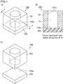
- FIG. 1(a) to FIG. 1(c) are schematic views showing an exemplary mold for use in a molding step.
- FIG. 1(a) is a perspective view schematically showing an exemplary mold for use in the molding step.
- FIG. 1(b) is a cross-sectional view taken along line A-A of FIG. 1(a).
- FIG. 1(c) is a perspective view schematically showing a state in which the mold shown in FIG. 1(a) is taken apart into constituent parts.
- a mold 100 includes a side mold 101 and a bottom mold 103. As shown in FIG. 1(b) , in the mold 100, a cavity V 1 is formed which is surrounded by an inner wall 101a of the side mold 101 and an upper bottom 103a of the bottom mold 103. As shown in FIG. 1(c) , preferably, the side mold 101 and the bottom mold 103 are separable from each other.
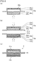
- FIG. 2(a) to FIG. 2(f) are schematic views showing an exemplary molding step.
- FIG. 2(a) shows an exemplary mold for use in the molding step.
- FIG. 2(b) shows an example in which the composition is injected into the mold in the molding step.
- FIG. 2(c) and FIG. 2(d) each show an example in which the composition is compressed.
- FIG. 2(e) shows an example in which the compressed electrode active material molded body is removed from the mold.
- the mold 100 includes the cavity V 1 with a bottom formed by the bottom mold 103 and a side formed by the side mold 101.
- a composition 110 is injected into the cavity V 1 , and compressed by a compression jig 104.
- the degree of compressing the composition 110 is not limited as long as it is the pressure at which the composition 110 can be molded.
- the composition may be compressed into an electrode active material molded body 15 (whose density is lower than that of the lithium-ion battery as the final product) shown in FIG. 2(c) or an electrode active material molded body 10 (which is a lithium-ion battery as the final product) shown in FIG. 2(d) .
- the electrode active material molded body 10 after molding is removed from the mold 100.
- the electrode active material molded body 15 shown in FIG. 2(c) may be removed from the mold 100.
- the electrode active material molded body 10 shown in FIG. 2(f) which is a molded body of the electrode active material composition is obtained.
- the composition contains the electrode active material for a lithium-ion battery and the electrolyte solution.
- the composition can be molded into a given shape by a method that uses a mold having a predetermined shape, for example, and the electrode active material molded body thus can be obtained.
- the electrode active material for a lithium-ion battery is a coated active material in which at least a portion of its surface is coated with a coating agent containing a coating resin, the coating agent containing the electrolyte solution swells and becomes viscous.
- the composition can be molded more easily.
- the term "injected" and its variants mean that the cavity of the mold is filled with the entire composition.
- the active material and the electrolyte solution constituting the composition are preferably injected in a uniformly mixed state.
- an alternative method may be employed in which only the active material is first placed in the mold and the active material is then immersed in the electrolyte solution, whereby the mold is filled with the composition.
- Shaking or giving a shock to the mold when the composition is injected into the cavity of the mold facilitates uniform injection of the composition into the mold.
- the composition has an electrolyte solution content of 0.1 to 40 wt% based on the weight of the composition.
- the state of the composition before molding can be a flowable solid-liquid mixture state (also referred to as a "slurry state"), a slightly flowable solid-liquid mixture state (also referred to as a "pendular state” or a "funicular state”), a gel state, wet powder state, or the like.
- the slurry state refers to the state of the composition in which all the gaps between at least active materials are filled with the electrolyte solution or in which the volume of the electrolyte solution is larger than the total volume of the gaps.
- the pendular state or the funicular state refer to the state in which the gaps between the active materials are partially filled with the electrolyte solution.
- the funicular state refers to the state obtained by mixing the active materials with the electrolyte solution having a volume less than the total volume of the gaps between the active materials.
- the pendular state, the funicular state, the gel state, and the wet powder state are preferred.
- the electrode active material has one of the above states, the composition can be molded more easily.
- a separator is placed in the mold having a bottom and a side so as to cover the entire bottom of the mold and at least a portion of the side of the mold, the composition is injected into the mold with the separator placed therein and molded, and the entire surface of the composition corresponding to the bottom of the mold and at least a portion of the surface of the composition corresponding to the side of the mold are continuously covered with the separator.
- the above method can produce an electrode active material molded body unit in which the electrode active material molded body is integrated with the separator in the molding step.
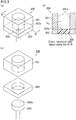
- FIG. 3(a) to FIG. 3(c) An exemplary mold that can be used to produce the electrode active material molded body unit is described with reference to FIG. 3(a) to FIG. 3(c) .
- FIG. 3(a) to FIG. 3(c) are schematic views showing another exemplary mold for use in the molding step.
- FIG. 3(a) is a perspective view schematically showing an exemplary mold for use in the molding step.
- FIG. 3(b) is a cross-sectional view taken along line B-B of FIG. 3(a).
- FIG. 3(c) is a perspective view schematically showing a state in which the mold shown in FIG. 3(a) is taken apart into constituent parts.
- a mold 200 includes a side mold 201, a bottom mold 203, and a corner mold 202.
- a cavity V 2 is formed which is surrounded by an inner wall 201a of the side mold 201 and an upper bottom 203a of the bottom mold 203.
- the side mold 201, the bottom mold 203, and the corner mold 202 may be separable from each other.
- corner mold 202 functions to fix the bottom mold 203 to a predetermined position in the state shown in FIG. 3(a) and FIG. 3(b)
- the corner mold 202 functions as a side mold when the bottom mold 203 is moved downwards in a step described later.
- the following describes a method of producing the electrode active material molded body unit in which the electrode active material molded body is integrated with the separator using the mold, with reference to FIG. 4(a) to FIG. 4(g) .
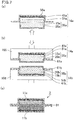
- FIG. 4(a) to FIG. 4(g) are illustrations schematically showing an exemplary molding step in which the mold shown in FIG. 3(a) to FIG. 3(c) is used.
- FIG. 4(a) to FIG. 4(g) are schematic views showing another exemplary molding step.
- FIG. 4(a) shows an exemplary mold for use in the molding step.
- FIG. 4(b) shows an example in which the separator is placed in the mold in the molding step.
- FIG. 4(c) shows an example in which the composition is injected into the mold.
- FIG. 4(d) to FIG. 4(f) show an example in which the composition is compressed.
- FIG. 4(g) shows an exemplary electrode active material molded body unit obtained by the steps shown in FIG. 4(a) to FIG. 4(f) .
- the mold 200 includes the cavity V 2 with a bottom formed by the bottom mold 203 and a side formed by the side mold 201.
- a separator 20 is placed on the bottom mold 203 and the corner mold 202 as shown in FIG. 4(b) .
- the separator 20 is placed on the bottom mold 203 and between the side mold 201 and the corner mold 202.
- the separator 20 covers the entire upper bottom of the bottom mold 203, and has an area larger than that of the top surface of the bottom mold 203.
- the separator 20 is placed between the side mold 201 and the corner mold 202. Yet, the side mold 201 and the corner mold 202 do not have to be separable (i.e., the mold 100 shown in FIG. 1(a) to FIG. 1(c) is used), and the separator 20 may be placed in the mold in such a manner that the separator 20 is bent in a U-shape.
- the separator 20 When the separator 20 is placed in a U-shape in the mold, in order to improve the contact between the separator 20 and the mold 200, the separator may be tightly attached to the bottom of the mold 200 by pushing the separator 20 against the upper bottom of the bottom mold 203 using a jig or the like having a shape corresponding to the shape of the cavity.
- the composition 110 containing an active material and an electrolyte solution is injected into the cavity V 2 in the mold 200 as shown in FIG. 4(c) .
- the separator 20 is placed on the bottom of the mold 200, so that the composition 110 injected into the mold 200 is placed on the separator 20.
- the composition 110 injected into the mold 200 is compressed using a compression jig 204 from a side opposite to the bottom mold 203, as shown in FIG. 4(d) and FIG. 4(e) .
- the compression jig 204 preferably has a shape substantially corresponding to the shape of the cavity V 2 formed in the mold 200.
- the composition 110 injected into the cavity V 2 is compressed using the compression jig 204, whereby the composition 110 is molded into the electrode active material molded body 15 shown in FIG. 4(d) . Further compression of the composition 110 results in an electrode active material molded body 11 shown in FIG. 4(e) .
- the bottom mold 203 is moved to the same direction as the compression direction of the compression jig 204, whereby ends 20c and 20d of the separator held between the side mold 201 and the corner mold 202 can be pulled out to the side of the corner mold 202 and placed on the side of the electrode active material molded body 11.
- the electrode active material molded body 11 can be integrated with the separator 20, and an electrode active material molded body unit 30 shown in FIG. 4(g) can be obtained in which the entire surface of the electrode active material molded body 11 corresponding to the bottom of the mold 200 and at least a portion of the surface of the electrode active material molded body 11 corresponding to the side of the mold 200 are continuously covered with the separator 20.
- the resulting electrode active material molded body unit 30 is preferably taken out from the bottom mold 203 side.
- the separator 20 placed on the side of the mold side may be separated or broken.
- the degree of compressing the composition 110 is not limited as long as it is the pressure at which the composition 110 can be molded.
- the composition may be compressed into the electrode active material molded body 15 (whose density is lower than that of the lithium-ion battery as the final product) shown in FIG. 4(d) or the electrode active material molded body 11 (which is a lithium-ion battery as the final product) shown in FIG. 4(e) .
- the molding step may involve moving the bottom mold 203 to the same direction as the compression direction of the compression jig 204 from the state shown in FIG.
- the mold may have any shape as long as it has a bottom and a side.
- the bottom mold may be integrated with the side mold. Yet, preferably, the side mold and the bottom mold are separable from each other as shown in FIG. 1(a) to FIG. 1(c) , and more preferably, the side mold can be divided into two parts at the height of the bottom as shown in FIG. 3(a) to FIG. 3(c) .
- the mold part constituting the portion lower the height of the bottom does not substantially constitute the side, and is thus also referred to as a "corner mold”.
- Examples of the material constituting the mold include materials such as metals generally used in the molds.
- the surface of the mold may be coated with fluorine or the like in order to reduce friction generated between the mold and the electrode active material molded body.
- the shape of the cavity formed in the mold may be adjusted according to the shape of the intended electrode active material molded body, and the shape is preferably constant in the compression direction. For example, a cylindrical shape or a prism shape is preferred.
- Use of a mold in which the cavity has a cylindrical shape results in an electrode active material molded body having a substantially circular shape in a plan view.
- Use of a mold in which the cavity has a prism shape results in an electrode active material molded body having a substantially rectangular shape in a plan view.
- the separator may be placed to cover the entire bottom and at least a portion of the side of the mold. Placing the separator to cover the entire bottom and at least a portion of the side of the mold makes it possible to obtain an electrode active material molded body unit in which the separator is integrated with the electrode active material molded body. Such an electrode active material molded body unit is preferred because there is no need to separately provide a separator when producing a lithium-ion battery by assembling the electrode active material molded body units together, improving handleability of the electrode active material molded body.
- the electrode active material molded body unit in which the entire surface corresponding to the bottom of the mold and at least a portion of the surface corresponding to the side of the mold are covered with the separator is preferred because when the electrode active material molded body unit is integrated with a battery housing in the assembly step, the exposed area of the electrode active material molded body is small, and the quality of the lithium-ion batteries produced tends to be consistent.
- the separator for use preferably has a shape that can completely cover the bottom of the mold and at least a portion of the side of the mold.
- the separator does not have to be tightly attached to the bottom of the mold, but it is more preferred that the separator is tightly attached thereto.
- the separator placed on the bottom of the mold is pressed against the bottom of the mold using a jig or the like.
- a folding line corresponding to the size of the electrode active material molded body after molding may be formed in the separator in advance, or a separator molded into a predetermined a three-dimensional shape may be placed in the mold in advance, in order to tightly attach the separator to the bottom and the side of the mold.
- the separator to be placed in the mold does not have to have a three-dimensional shape that is tightly attached to the bottom and the side of the mold.
- the separator may be formed into a three-dimensional shape that is tightly attached to the bottom and the side of the mold, when the composition is injected into or compressed in the mold with the separator placed therein.
- the area of the separator is large enough to cover the entire surface of the electrode active material molded body corresponding to the bottom of the mold (i.e., the bottom of the electrode active material molded body) and at least a portion of the surface of the electrode active material molded body corresponding to the side of the mold (i.e., the side of the electrode active material molded body). More preferably, the area of the separator is large enough to cover the entire surface corresponding to the bottom of the mold and the entire surface corresponding to the side of the mold.
- the area of the separator is large enough to cover not only the entire surface corresponding to the bottom of the mold and the entire surface corresponding to the side of the mold but also the surface corresponding to the surface opposite to the bottom of the mold (i.e., the top of the electrode active material molded body).
- the current collector needs to be placed in such a manner that a portion of the current collector placed inside the separator (the electrode active material molded body side) is exposed to the outside.
- the current collector is folded in between overlapping separators, or a slit is formed in the separator and the current collector is led out through the slit.
- the separator When the separator is placed to cover the entire bottom of the electrode active material molded body, direct contact between the positive electrode active material molded body and the negative electrode active material composition can be prevented.
- the separator is placed to further cover the entire bottom and at least a portion of the side of the electrode active material molded body (more preferably, the entire bottom, the entire side, and the entire top of the electrode active material molded body).
- each electrode active material molded body is small when the electrode active material molded body is integrated with the battery housing, so that direct contact between the positive electrode members (the positive electrode current collector and the positive electrode active material molded body) and the negative electrode members (the negative electrode current collector and the negative electrode active material molded body) in the battery is prevented, and thus, the quality of the lithium-ion batteries produced tends to be consistent.
- the method when the molding step is performed without placing a separator, the method may include an additional step of covering the surface of the electrode active material molded body with a separator after the molding step.
- preferred regions of the surface of the electrode active material molded body to be covered with the separator, the area of the separator, and the arrangement of the current collector are the same as those in the case where the electrode active material molded body is covered with the separator in the molding step.
- Examples of materials constituting the separator include microporous films made of polyethylene or polypropylene; multilayer films consisting of a porous polyethylene film and a porous polypropylene; non-woven fabric made of polyester fibers, aramid fibers, or glass fibers; and such non-woven fabric with ceramic fine particles such as silica, alumina, or titania particles attached to the surface thereof.
- the electrode active material molded body is preferably such that 5 to 100% of the side is covered with the separator.
- the pressing strength of the compression jig against the composition is not limited, but it is preferably 10 to 2000 MPa, more preferably 50 to 1000 MPa.
- the proportion of the injected molded composition is preferably 40 to 70% when the active material is a positive electrode active material (i.e., the positive electrode active material molded body), and is preferably 50 to 80% when the active material is a negative electrode active material (i.e., the negative electrode active material molded body).
- the above proportion is represented by the ratio (volume percentage) of the volume of solids contained in the electrode active material molded body to the volume of the electrode active material molded body.
- extrusion is one of methods of obtaining the electrode active material molded body.
- an exemplary method of obtaining an electrode active material molded body by extrusion a conventionally known extruder is used.
- the extruder may be one including a feeding tube through which a raw material is fed, a die (also referred to as a "mold") attached to the raw material discharge side of the feeding tube, and a rotating shaft screw that extrudes the raw material placed in the feeding tube into the die.
- a feeding tube through which a raw material is fed
- a die also referred to as a "mold”
- a rotating shaft screw that extrudes the raw material placed in the feeding tube into the die.
- An active material and an electrolyte solution which are raw materials of the electrode active material molded body, are fed into the feeding tube, and the active material and the electrolyte solution that were moved through the feeding tube by the rotation of the screw are extruded from the die, whereby an electrode active material molded body can be obtained.
- the shape of the electrode active material molded body can be suitably adjusted by adjusting the shape of the die and the rotation speed of the screw.
- the shape of the composition discharged from the die is not limited, but it is preferably a cylindrical shape or a quadrangular prism shape.
- the composition discharged from the die is cut into a predetermined length, whereby an electrode active material molded body for a lithium-ion battery is obtained.
- the method of cutting the composition discharged from the die is not limited. Examples include a method that uses a rotary cutter or a thread.
- the temperature of the composition during extrusion is not limited, but it is preferably 40°C or lower in view of moldability or the like.
- a preferred mixing ratio of the active material and the electrolyte solution and preferred properties of the composition before molding are the same as those in the case of compression molding using a mold.
- the electrode active material molded body obtained by extrusion may be accommodated into an accommodating portion of a battery housing in the same manner as in the case of an electrode active material molded body obtained by a method of molding an electrode active material molded body without placing a separator in a mold.
- a known roll pressing machine is used.
- a mixture of an active material and an electrolyte solution is fed from a continuous mixer such as a kneader; the mixture is spread to a certain thickness on a smooth surface such as a film by a doctor blade or the like; and the mixture is roll-pressed, whereby a sheet of an electrode active material molded body can be obtained.
- the sheet of the electrode active material molded body is cut into a predetermined length, and the molding step is thus completed.
- a preferred mixing ratio of the active material and the electrolyte solution and preferred properties of the composition before molding are the same as those in the case of compression molding using a mold.
- the electrode active material molded body for a lithium-ion battery obtained by the method of producing an electrode active material molded body for a lithium-ion battery of the present invention contains an electrolyte solution.
- the amount of the electrolyte solution is optimal for the molding step, the battery performance of the resulting lithium-ion battery may be insufficient.
- the electrolyte solution may be additionally added to the electrode active material molded body.
- the composition contains the active material and the electrolyte solution, and may contain a conductive additive and a viscosity modifier, for example, if necessary.
- the amount of the electrolyte solution in the composition is 0.1 to 40.0 wt%.
- the composition before molding (the mixture of the active material and the electrolyte solution) is an unbound product of a mixture of the electrode active material for a lithium-ion battery and the electrolyte solution.
- An electrode active material molded body obtained by molding the composition is also an unbound product of a mixture of the electrode active material for a lithium-ion battery and the electrolyte solution.
- an electrode active material molded body for a lithium-ion battery obtained by molding the composition containing these components is also an unbound product of a mixture of the electrode active material for a lithium-ion battery and the electrolyte solution.
- the composition has an electrolyte solution content of 0.1 to 40 wt% based on the weight of the composition.
- the liquid bridge force is weak, resulting in insufficient shape retainability of the molded body.
- the composition has an electrolyte solution content of more than 40 wt%, a composition is liquefied, resulting in insufficient shape retainability of the molded body.
- the electrolyte solution content in the composition can be adjusted within the above range by adjusting the amount of the electrolyte solution to be added to the active material.
- the composition preferably has an electrolyte solution content of 5 to 35 wt%, more preferably 10 to 30 wt%, based on the weight of the composition.
- an electrolyte solution content is in the above range, a molded body having a high density and high shape retainability can be obtained even with low pressure.
- an electrolyte solution instead of an organic solvent as a process auxiliary material, there is no need to distill off the organic solvent after molding of the molded body, which can significantly decrease the number of steps.
- the amount of the electrolyte solution in the composition is sufficient in view of shape retainability during molding of the composition, but may be insufficient to provide sufficient battery performance of the lithium-ion battery.
- the electrolyte solution is additionally added to the molded body, whereby the amount of the electrolyte solution in the molded body can be adjusted.
- the added electrolyte solution can easily penetrate into the composition, without reducing the pressure or the like, and the time required for absorption of the electrolyte solution can be reduced.
- the weight percentage of the active material contained in the composition is preferably 80 to 100 wt% based on the total solids weight of the composition in view of balance between shape retainability and battery performance.
- the electrode active material for a lithium-ion battery is a coated active material in which at least a portion of its surface is coated with a coating agent containing a coating resin, the weight of the coating agent is excluded from the weight of the active material.
- An active material layer of the conventional lithium-ion battery (which corresponds to the electrode active material molded body in the method of producing a lithium-ion battery of the present invention) is produced by applying slurry in which active materials and a binder are dispersed in a solvent to the surface of a current collector or the like and thermally drying the slurry.
- the active material layer is fixed by the binder.
- the active materials are bound together by the binder, and the position of the active materials is irreversibly fixed.
- the electrode active materials for a lithium-ion battery in the electrode active material molded body produced by the method are not bound together, and the position of the electrode active materials for a lithium-ion battery is also not fixed.
- the electrode active materials for a lithium-ion battery in the composition can be easily loosened by hand, and the state of the composition can be checked.
- binder examples include known binders for lithium-ion batteries such as starch, polyvinyl alcohol, carboxymethyl cellulose, polyvinylpyrrolidone, tetrafluoroethylene, styrene-butadiene rubber, polyethylene, polypropylene, polyvinylidene fluoride (PVdF), and styrene-butadiene rubber (SBR).
- these compounds are not added as binders to the composition, and more preferably, these compounds are not used as compounds to constitute a coating agent (described later).
- the electrode active material for a lithium-ion battery constituting the electrode active material molded body may be a positive electrode active material or a negative electrode active material.
- the composition containing a positive electrode active material as the electrode active material for a lithium-ion battery is also referred to as a "positive electrode composition".
- the composition containing a negative electrode active material as the electrode active material for a lithium-ion battery is also referred to as a "negative electrode composition”.
- the coating agent in which the electrode active material for a lithium-ion battery is a positive electrode active material is also referred to as a "positive electrode coating agent”.
- the coating agent in which the electrode active material for a lithium-ion battery is a negative electrode active material is also referred to as a "negative electrode coating agent”.
- the electrode active material molded body whose composition is a positive electrode composition is also referred to as a "positive electrode active material molded body".
- the electrode active material molded body whose composition is a negative electrode composition is also referred to as a "negative electrode active material molded body".
- the electrode active material molded body unit whose composition is a positive electrode composition is also referred to as a "positive electrode active material molded body unit”.
- the electrode active material molded body unit whose composition is a negative electrode composition is also referred to as a "negative electrode active material molded body unit”.
- the positive electrode active material molded body is assembled with the negative electrode active material molded body such that their compositions are placed with a separator therebetween, and the assembly is surrounded by a battery housing or the like, whereby a lithium-ion battery is produced.
- the positive electrode active material constituting the positive electrode composition may be suitably a conventionally known one.
- the positive electrode active material can be a compound that is capable of inserting and desorbing lithium ions at a certain electric potential and that is capable of inserting and desorbing lithium ions at a higher electric potential than the negative electrode active material used as a counter electrode.
- the lithium-containing transition metal phosphates may be those in which the transition metal site is partially replaced by another transition metal.
- the volume average particle size of the positive electrode active material is preferably 0.01 to 100 ⁇ m, more preferably 0.1 to 35 ⁇ m, still more preferably 1 to 30 ⁇ m.
- the negative electrode active material examples include carbon materials (e.g., graphite, non-graphitizable carbon, amorphous carbon, products obtained by firing resin (e.g., products obtained by firing and carbonating phenol resin and furan resin), coke (e.g., pitch coke, needle coke, and petroleum coke), silicon carbide, and carbon fibers); conductive polymers (e.g., polyacetylene and polypyrrole); metals (e.g., tin, silicon, aluminum, zirconium, and titanium); metal oxides (e.g., titanium oxide, lithium-titanium oxide, and silicon oxide); and metal alloys (e.g., lithium-tin alloy, lithium-silicon alloy, lithium-aluminum alloy; lithium-aluminum-manganese alloy); and and mixtures of these materials and a carbon material.
- carbon materials e.g., graphite, non-graphitizable carbon, amorphous carbon, products obtained by firing resin (e.g
- those not containing lithium or lithium ions inside may be predoped to allow the active material to partially or entirely contain lithium or lithium ions in advance.
- the volume average particle size of the negative electrode active material is preferably 0.01 to 100 ⁇ m, more preferably 0.1 to 40 ⁇ m, still more preferably 2 to 35 ⁇ m.
- volume average particle size of the positive electrode active material and the negative electrode active material refers to the particle size at cumulative 50% (Dv 50) in a particle size distribution determined by the Microtrac method (laser diffraction and scattering method).
- the Microtrac method determines a particle size distribution by using light scattered from the particles irradiated with laser light.
- the volume average particle size can be measured using a device such as Microtrac (Nikkiso Co., Ltd.).
- the electrode active material for a lithium-ion battery is preferably a coated active material in which at least a portion of its surface is coated with a coating agent containing a coating resin.
- the coating agent containing the electrolyte solution swells and becomes viscous.
- the composition can be molded more easily.
- the coated active material is an electrode active material for a lithium-ion battery in which at least a portion of its surface is coated with the coating agent containing a coating resin.
- the coating agent contains a coating resin, and may further contain a conductive material, if necessary.
- the coated active material is one in which at least a portion of the surface of the electrode active material for a lithium-ion battery is coated with the coating agent containing a coating resin.
- the coating agent containing a coating resin containing a coating resin.
- the coating resin examples include thermoplastic resins and thermosetting resins, such as fluororesin, acrylic resin, urethane resin, polyester resin, polyether resin, polyamide resin, epoxy resin, polyimide resin, silicone resin, phenol resin, melamine resin, urea resin, aniline resin, ionomer resin, polycarbonate, polysaccharide (e.g., sodium alginate), and mixtures thereof.
- thermoplastic resins and thermosetting resins such as fluororesin, acrylic resin, urethane resin, polyester resin, polyether resin, polyamide resin, epoxy resin, polyimide resin, silicone resin, phenol resin, melamine resin, urea resin, aniline resin, ionomer resin, polycarbonate, polysaccharide (e.g., sodium alginate), and mixtures thereof.
- thermoplastic resins and thermosetting resins such as fluororesin, acrylic resin, urethane resin, polyester resin, polyether resin, polyamide resin, epoxy resin, polyimide resin, silicone resin, phenol resin
- a more preferred coating resin is one having a liquid absorption rate of 10% or more when immersed in an electrolyte solution and having a tensile elongation at break of 10% or more when saturated with the electrolyte solution.
- the liquid absorption rate of the coating resin when immersed in an electrolyte solution can be determined by measuring the weight of the coating resin before and after immersion in the electrolyte solution and using the following formula.
- Liquid absorption rate % ⁇ Weight of coating resin after immersion in electrolyte solution > ⁇ ⁇ Weight of coating resin before immersion in electrolyte solution > / Weight of coating resin before immersion in electrolyte solution ⁇ 100
- the electrolyte solution to be used to determine the liquid absorption rate is preferably an electrolyte solution in which LiPF 6 as an electrolyte is dissolved to a concentration of 1 mol/L in a solvent mixture in which ethylene carbonate (EC) and diethyl carbonate (DEC) are mixed in a volume ratio (EC:DEC) of 1:1.
- EC ethylene carbonate
- DEC diethyl carbonate
- the coating resin is immersed in the electrolyte solution at 50°C for 3 days.
- the coating resin will be saturated with the electrolyte solution after being immersed in the electrolyte solution at 50°C for 3 days.
- saturated with the electrolyte solution refers to the state where the weight of the coating resin does not increase anymore even if the coating resin is immersed in the electrolyte solution for a longer time.
- the electrolyte solution to be used for the production of the lithium-ion battery is not limited to the electrolyte solution mentioned above. Any other electrolyte solution may be used.
- the lithium ions can easily pass through the coating resin, so that ionic resistance in the composition can be maintained at a low level.
- the liquid absorption rate is less than 10%, the conductivity of lithium ions may decrease, resulting in poor performance of the lithium-ion battery.
- the liquid absorption rate is more preferably 20% or more, still more preferably 30% or more.
- the upper limit of the liquid absorption rate is preferably 400%, more preferably 300%.
- the tensile elongation at break of the coating resin when saturated with the electrolyte solution can be measured as follows: the coating resin is punched into a dumbbell shape; the dumbbell-shaped coating resin is immersed in an electrolyte solution at 50° for 3 days in the same manner as in the measurement of the liquid absorption rate so as to be saturated with the electrolyte solution; and the tensile elongation at break is measured according to ASTM D683 (specimen's shape: Type II).
- the tensile elongation at break is the rate of elongation until the specimen breaks in a tensile test as calculated by the following formula:
- Tensile strength at break % Specimen's length at break ⁇ Specimen's length before test / Specimen's length before test ⁇ 100
- the coating resin having a tensile elongation at break of 10% or more when saturated with the electrolyte solution has adequate flexibility. This helps preventing the coating agent from being separated due to volume changes in the electrode active material for a lithium-ion battery during charging and discharging.
- the tensile elongation at break is more preferably 20% or more, still more preferably 30% or more.
- the upper limit of the tensile elongation at break is preferably 400%, more preferably 300%.
- the one described as the coating resin in WO 2015/005117 can be particularly preferably used as the coating resin constituting the coating agent in the method of producing an electrode active material molded body for a lithium-ion battery of the present invention.
- the conductive material is selected from materials having conductivity.
- metals e.g., nickel, aluminum, stainless steel (SUS), silver, copper, and titanium
- carbon e.g., graphite and carbon black (e.g., acetylene black, ketjen black, furnace black, channel black, and thermal lamp black)
- mixtures thereof include, but not be limited to, metals (e.g., nickel, aluminum, stainless steel (SUS), silver, copper, and titanium), carbon (e.g., graphite and carbon black (e.g., acetylene black, ketjen black, furnace black, channel black, and thermal lamp black)), and mixtures thereof.
- These conductive materials may be used alone or in combination of two or more. Alloys or metal oxides thereof may also be used. In view of electrical stability, preferred are aluminum, stainless steel, carbon, silver, copper, titanium, and mixtures thereof, more preferred are silver, aluminum, stainless steel, and carbon, and still more preferred is carbon. These conductive materials may be particulate ceramic materials or resin materials coated with conductive materials (metals among the conductive materials described above) by plating or the like.
- the conductive material can have any average particle size. Yet, in view of the electrical characteristics of the lithium-ion buttery, the average particle size is preferably 0.01 to 10 ⁇ m, more preferably 0.02 to 5 ⁇ m, still more preferably 0.03 to 1 ⁇ m.
- particle size refers to the largest distance L among distances between any two points on the outline of a particle.
- the “average particle size” can be determined as follows: particles are observed with a scanning electron microscope (SEM) or a transmission electron microscope (TEM), for example, and the average of the particle sizes of the particles observed in several to several tens of viewing fields is calculated. The thus calculated value is defined as the average particle size.
- the shape (form) of the conductive material is not limited to the particulate form and may be a different form.
- the conductive material may be a carbon nanotube which has been practically used as a filler-type conductive material.
- the conductive material may be in the form of fibrous-shaped conductive fibers.
- the conductive fiber examples include carbon fibers such as PAN-based carbon fibers and pitch-based carbon fibers; conductive fibers obtained by uniformly dispersing highly conductive metal or graphite in synthetic fibers; metal fibers obtained by making metal such as stainless steel into fibers; conductive fibers obtained by coating the surface of organic fibers with metal; and conductive fibers obtained by coating the surface of organic fibers with a resin containing a conductive substance.
- carbon fibers are preferred.
- Polypropylene resin into which graphene has been kneaded is also preferred.
- the average fiber dimeter is preferably 0.1 to 20 ⁇ m.
- the electrode active material for a lithium-ion battery is a positive electrode active material.
- the total weight percentage of the coating resin and the conductive material relative to the weight of the positive electrode active material is not limited, but it is preferably 2 to 25 wt%.
- the weight percentage of the coating resin relative to the weight of the positive electrode active material is not limited, but it is preferably 0.1 to 10 wt%.
- the weight percentage of the conductive material relative to the weight of the positive electrode active material is not limited, but it is preferably 2 to 15 wt%.
- the conductivity of the positive electrode coating agent is preferably 0.001 to 10 mS/cm, more preferably 0.01 to 5 mS/cm.
- the conductivity of the positive electrode coating agent can be measured by the four-terminal method.
- the conductivity of the positive electrode coating agent is 0.001 mS/cm or more, the electric resistance to the positive electrode active material molded body is unlikely to increase.
- the electrode active material for a lithium-ion battery is a negative electrode active material.
- the total weight percentage of the coating resin and the conductive material contained in the negative electrode coating agent is not limited, but it is preferably 25 wt% or less relative to the weight of the negative electrode active material.
- the weight percentage of the coating resin relative to the weight of the negative electrode active material is not limited, but it is preferably 0.1 to 20 wt%.
- the weight percentage of the conductive material relative to the weight of the negative electrode active material is not limited, but it is preferably 10 wt% or less.
- Examples of the conductive additive that may be contained in the composition include those of the conductive material that may be contained in the coating agent.
- the electrolyte solution may be one containing an electrolyte and a non-aqueous solvent, which is used in the production of a lithium-ion battery.
- the electrolyte may be one that is used in known electrolyte solutions.
- electrolytes containing lithium salts of inorganic acids such as LiPF 6 , LiBF 4 , LiSbF 6 , LiAsF 6 , and LiClO 4
- imide-based electrolytes such as LiN(SO 2 CF 3 ) 2 and LiN(SO 2 C 2 F 5 ) 2
- alkyl lithium-based electrolyte such as LiC(SO 2 CF 3 ) 3 .
- LiPF 6 is preferred in view of ion conductivity and thermal decomposition temperature when the concentration of the electrolyte solution is high.
- LiPF 6 may be used in combination with another electrolyte but is more preferably used alone.
- the concentration of the electrolyte solution is not limited, but it is preferably 0.5 to 5 mol/L, more preferably 0.8 to 4 mol/L, still more preferably 1 to 2 mol/L.
- the non-aqueous solvent can be one that is used in known electrolyte solutions.
- Examples include lactone compounds, cyclic or acyclic carbonate esters, acyclic carboxylate esters, cyclic or acyclic ethers, phosphate esters, nitrile compounds, amide compounds, sulfone, and mixtures thereof.
- lactone compounds examples include 5-membered lactone compounds (e.g., ⁇ -butyrolactone and ⁇ -valerolactone) and 6-membered lactone compounds (e.g., ⁇ -valerolactone).
- cyclic carbonate esters examples include propylene carbonate, ethylene carbonate, and butylene carbonate.
- Examples of the acyclic carbonate esters include dimethyl carbonate, methyl ethyl carbonate, diethyl carbonate, methyl-n-propyl carbonate, ethyl-n-propyl carbonate, and di-n-propyl carbonate.
- acyclic carbonate esters examples include methyl acetate, ethyl acetate, propyl acetate, and methyl propionate.
- cyclic ethers examples include tetrahydrofuran, tetrahydropyran, 1,3-dioxolan, and 1,4-dioxane.
- Examples of the acyclic ethers include dimethoxymethane and 1,2-dimethoxyethane.
- phosphate esters examples include trimethyl phosphate, triethyl phosphate, ethyl dimethyl phosphate, diethyl methyl phosphate, tripropyl phosphate, tributyl phosphate, tri(trifluoromethyl) phosphate, tri(trichloromethyl) phosphate, tri(trifluoroethyl) phosphate, tri(triperfluoroethyl) phosphate, 2-ethoxy-1,3,2-dioxaphospholan-2-one, 2-trifluoroethoxy-1,3,2-dioxaphospholan-2-one, and 2-methosyethoxy-1,3,2-dioxaphospholan-2-one.
- Examples of the nitrile compounds include acetonitrile.
- Examples of the amide compounds include DMF.
- Examples of the sulfone include acyclic sulfones such as dimethyl sulfone and diethyl sulfone and cyclic sulfones such as sulfolane.
- Each of these non-aqueous solvents may be used alone or in combination of two or more thereof.
- lactone compounds are preferred in view of output and charge/discharge cycle characteristics of the lithium-ion battery. More preferred are lactone compounds, cyclic carbonate esters, and acyclic carbonate esters. Particularly preferred are cyclic carbonate esters and mixtures of a cyclic carbonate ester and an acyclic carbonate ester. The most preferred are a mixture of ethylene carbonate (EC) and propylene carbonate (PC), a mixture of ethylene carbonate (EC) and dimethyl carbonate (DMC), and a mixture of ethylene carbonate (EC) and diethyl carbonate (DEC).
- EC ethylene carbonate
- PC propylene carbonate
- DMC dimethyl carbonate
- DEC diethyl carbonate
- the following describes a first embodiment of the method of producing a lithium-ion battery of the present invention.
- the first embodiment of the method of producing a lithium-ion battery of the present invention at least includes an assembly step of placing the electrode active material molded body for a lithium-ion battery produced by the method of producing an electrode active material molded body for a lithium-ion battery of the present invention in an accommodating portion formed in at least a portion of a battery housing, and integrating the electrode active material molded body with the battery housing to prepare an electrode structure.
- the electrode active material for a lithium-ion battery is preferably a coated active material in which at least a portion of its surface is coated with a coating agent containing a coating resin.
- the coating agent containing the electrolyte solution swells and becomes viscous.
- the composition can be molded more easily.
- the first embodiment of the method of producing a lithium-ion battery of the present invention is described with reference to FIG. 5(a) to FIG. 5(c) .
- a molding step in the first embodiment of the method of producing a lithium-ion battery of the present invention is the same as the molding step constituting the method of producing an electrode active material molded body for a lithium-ion battery of the present invention. Thus, a description thereof is omitted.
- FIG. 5(a) to FIG. 5(c) are schematic views showing an exemplary method of producing a lithium-ion battery of the present invention.
- FIG. 5(a) is an illustration schematically showing an exemplary assembly step.
- FIG. 5(b) and FIG. 5(c) are schematic views showing an exemplary method of producing a lithium-ion battery using an electrode structure prepared in the assembly step.
- a positive electrode active material molded body 10a is placed in a positive electrode accommodating portion 55a formed in at least a portion of a positive electrode housing 50a, and the positive electrode active material molded body 10a is integrated with the positive electrode housing 50a, whereby a positive electrode structure 12a is obtained.
- another positive electrode current collector 40a may be placed to be in contact with the positive electrode active material molded body 10a as shown in FIG. 5(a) .
- the following describes a method of producing a lithium-ion battery using the electrode structure obtained in the assembly step with reference to FIG. 5(b) and FIG. 5(c) .
- the production of a lithium-ion battery using the electrode structure obtained in the assembly step requires two different types of electrodes having different active materials.
- FIG. 5(b) and FIG. 5(c) describe a method of producing a lithium-ion battery using a positive electrode structure in which the electrode active material is a positive electrode active material and a negative electrode structure in which the electrode active material is a negative electrode active material.
- the positive electrode structure 12a in which the electrode active material molded body is the positive electrode active material molded body 10a and a negative electrode structure 12b in which the electrode active material molded body is a negative electrode active material molded body 10b are placed to face each other with a separator 21 therebetween.
- the structure of the negative electrode structure 12b is substantially the same as that of the positive electrode structure 12a, and a negative electrode current collector 40b is placed between the negative electrode active material molded body 10b and a negative electrode housing 50b.
- An insulating adhesive resin layer 60a is placed on a surface of the positive electrode housing 50a opposite to the negative electrode housing 50b, excluding the portion where the accommodating portion is formed.
- An insulating adhesive resin layer 60b is placed on a surface of the positive electrode housing 50b opposite to the positive electrode housing 50a, excluding a portion where the accommodating portion is formed. This prevents direct contact between the positive electrode housing 50a and the negative electrode housing 50b, thus preventing a short circuit.
- a sealing step of bonding and sealing the positive electrode housing 50a and the negative electrode housing 50b together by the adhesive resin layers 60a and 60b is performed, a lithium-ion battery 1 is obtained in which the positive electrode housing 50a and the negative electrode housing 50b are sealed together by an adhesive resin layer 60 as shown in FIG. 5(c) .
- the method of producing a lithium-ion battery of the present invention may use electrode active material molded body units each in which the electrode active material molded body is integrated with the separator, instead the electrode active material molded bodies described in FIG. 5(a) to FIG. 5(c) .
- a method of producing a lithium-ion battery using an electrode active material molded body unit is described with reference to FIG. 6(a) to FIG. 6(c) .
- FIG. 6(a) to FIG. 6(c) are schematic views showing another exemplary method of producing a lithium-ion battery of the present invention.
- FIG. 6(a) is an illustration schematically showing another exemplary assembly step.
- FIG. 6(b) and FIG. 6(c) are illustrations schematically showing another exemplary method of producing a lithium-ion battery using the electrode structure obtained in the assembly step.
- a positive electrode active material molded body unit 30a in which a positive electrode active material molded body 11a is integrated with the separator 20a is accommodated into a positive electrode accommodating portion 56a of a positive electrode housing 51a.
- the separator 20a is placed opposite to the positive electrode housing 51a across the positive electrode active material molded body 11a, and a positive electrode current collector 41a is placed between the positive electrode housing 51a and the positive electrode active material molded body 11a.
- a positive electrode structure 13a the positive electrode active material molded body unit 30a is accommodated in the positive electrode accommodating portion 56a of the positive electrode housing 51a.
- a negative electrode structure 13b a negative electrode active material molded body unit 30b in which a negative electrode active material molded body 11b is integrated with the separator 20b is accommodated in the accommodating portion of the negative electrode housing 51b, and a negative electrode current collector 41b is placed between the negative electrode active material molded body unit 30b and the negative electrode housing 51b.
- the positive electrode structure 13a and the negative electrode structure 13b are bonded together by an adhesive resin layer 61 (61a, 61b), whereby a lithium-ion battery 2 shown in FIG. 6(c) is obtained.
- a step of placing the separator as shown in FIG. 5(b) can be omitted, thus simplifying the production process.
- placing the separator it is required to place the separator in such a manner that the separator covers the area larger than the contact area between the positive electrode active material and the negative electrode active material in order to prevent contact between the positive electrode active material and the negative electrode active material.
- the minimum area that can seal the battery housing is increased by the area of the separator sticking out of the contact area between the positive electrode active material and the negative electrode active material.
- the electrode active material molded body unit prepared in the assembly step may be one in which the electrode active material molded body sticks out of the accommodating portion of the battery housing.
- a lithium-ion battery can be produced by compressing the electrode active material molded body when sealing the battery housings.
- FIG. 7(a) to FIG. 7(c) are schematic views showing still another exemplary method of producing a lithium-ion battery of the present invention.
- FIG. 7(a) is an illustration schematically showing another exemplary assembly step in the method of producing a lithium-ion battery of the present invention.
- FIG. 7(b) and FIG. 7(c) are illustrations schematically showing a method of producing a lithium-ion battery using the electrode structure prepared in the assembly step.
- a positive electrode active material molded body unit 35a in which a positive electrode active material molded body 15a is integrated with the separator 20a is accommodated into the positive electrode accommodating portion 56a of the positive electrode housing 51a, whereby a positive electrode structure 14a is prepared.
- the positive electrode active material molded body unit 35a corresponds to an electrode active material molded body unit that can be obtained by performing compression up to the molding step shown in FIG. 4(d) but not continuing the compression until the molding step shown in FIG. 4(e) .
- the volume of the positive electrode accommodating portion 56a is smaller than the total volume of the positive electrode active material molded body 15a and the separator 20a.
- the positive electrode active material molded body unit 35a partially sticks out of the positive electrode accommodating portion 56a of the positive electrode housing 51a.
- a negative electrode active material molded body unit 35b of a negative electrode structure 14b also sticks out from a negative electrode accommodating portion of the negative electrode housing 51b.
- the sealing step is performed in which the positive electrode housing 51a and the negative electrode housing 51b are bonded and sealed together by the adhesive resin layer 61 (61a, 61b), whereby the lithium-ion battery 2 shown in FIG. 7(c) is obtained.
- the positive electrode active material molded body 15a and the negative electrode active material molded body 15b are compressed to the same density as that in the molding step shown in FIG. 4(e) , whereby the positive electrode active material molded body 15a and the negative electrode active material molded body 15b are compressed into the positive electrode active material molded body 11a and the negative electrode active material molded body 11b, respectively, and the lithium-ion battery 2 shown in FIG. 7(c) which is the same as the lithium-ion battery 2 shown in FIG. 6(c) is obtained.
- the electrode active material molded body obtained in the molding step is placed in the accommodating portion formed in at least a portion of the battery housing, and the electrode active material molded body is integrated with the battery housing, whereby an electrode structure is prepared.
- the method of placing the electrode active material molded body in the accommodating portion of the battery housing is not limited. Examples include a method in which the battery housing is placed to cover the electrode active material molded body placed on a smooth surface, and a method in which the electrode active material molded body is placed to be accommodated in the accommodating portion of the battery housing placed on the smooth surface.
- the battery housing may also function as a current collector, or a current collector may be placed on the inner surface of the battery housing (on the surface that comes into contact with the electrode active material molded body).
- Suitable examples of a material that functions as a current collector include materials of a metal current collector and materials of a resin current collector formed of a conducting agent and a resin.
- the metal current collector may be, for example, a thin sheet or foil of one or more metal materials selected from the group consisting of copper, aluminum, titanium, nickel, tantalum, niobium, hafnium, zirconium, zinc, tungsten, bismuth, antimony, an alloy containing at least one of these materials, and a stainless steel alloy; or a substrate in which the metal material is formed on its surface by a means such as sputtering, electrodeposition, or application.
- the battery housing may be one including a resin layer formed from an insulating resin on a portion or the whole of the surface of the current collector.
- Examples of the current collector including a resin layer on its surface include laminated aluminum foil (an aluminum laminated film).
- the resin layer may consist of a single layer or a laminate.
- a portion of the battery housing which comes into contact with the other battery housing constituting the counter electrode is provided with a layer formed from an adhesive resin capable of allowing the battery housings to adhere to each other.
- the resin layer formed from the adhesive resin is also referred to as an "adhesive resin layer".
- the adhesive resin layer is not limited as long as it is a material having adhesiveness to a battery housing material and durability against the electrolyte solution.
- a polymer material particularly a thermosetting resin or a thermoplastic resin
- Specific examples include epoxy resin, polyolefin resin, polyurethane resin, and polyvinylidene fluoride resin.
- Epoxy resin is preferred in view of high durability and easy handleability.
- the resin adhesive layer can be, for example, double-sided tape made of the above material (one formed by applying the thermosetting resin or thermoplastic resin to both sides of a flat substance).
- a known one such as a three-layer sealing film (e.g., a film obtained by laminating modified polypropylene films or epoxy resin films with a polyethylene naphthalate film therebetween).
- Preferred examples of the conducting agent constituting the resin current collector include the same conductive materials that may be contained in the coating agent.
- the battery housing includes an accommodating portion at least in a portion thereof, and the volume of the accommodating portion is sufficient to accommodate the entire or a portion of the electrode active material molded body to be accommodated therein.
- the volume of the accommodating portion is equal to or smaller than the volume of the electrode active material molded body.
- the present invention involves sealing the positive electrode housing and the negative electrode housing together while compressing the positive electrode active material molded body and the negative electrode active material molded body, whereby the electrode active material molded body is compressed.
- the size and shape of the accommodating portion are not limited, but the volume of the accommodating portion is preferably 50 to 96 vol% of the volume of the electrode active material molded body to be accommodated.
- the shape of the accommodating portion is not limited, but the shape is preferably not so complicated, considering compression of the electrode active material molded body.
- the shape is preferably one that is substantially circular in a plan view and substantially rectangular in a cross-sectional view, or one that is polygonal in a plan view and substantially rectangular in a cross-sectional view.
- the corners may be rounded.
- the battery housing may be a battery housing in which multiple accommodating portions are regularly placed at regular intervals. Use of such a battery housing makes it possible to obtain an electrode structure in which the electrode active material molded body is placed in each accommodating portion. The thus-obtained electrode structure may be cut by each accommodating portion, if necessary, before or after the assembly step.
- the molding step and the assembly step may be performed simultaneously.
- the battery housing including an accommodating portion at least in a portion thereof is placed in a mold having a predetermined shape such that the shape of the accommodating portion fits the shape of the mold, a composition is injected into the accommodating portion, and the composition is compression-molded by a jig or the like.
- the molding step and the assembly step can be performed simultaneously.
- the molding step and the assembly step may be performed continuously in the same site, or the assembly step may be performed in a different site after the molding step is performed.
- the positive electrode structure or the negative electrode structure is produced in the molding step. Yet, it is preferred that both the positive electrode structure and the negative electrode structure are produced in the molding step.
- three or more electrode active material molded bodies may be accommodated in the battery housing.
- a second embodiment of the method of producing a lithium-ion battery of the present invention includes: an accommodating step of accommodating the electrode active material molded body for a lithium-ion battery produced by the method of producing an electrode active material molded body for a lithium-ion battery of the present invention into a battery housing, wherein in the molding step, a positive electrode active material molded body in which the electrode active material for a lithium-ion battery is a positive electrode active material and a negative electrode active material molded body in which the electrode active material for a lithium-ion battery is a negative electrode active material are prepared, and in the accommodating step, the positive electrode active material molded body and the negative electrode active material molded body are accommodated into the battery housing such that a plurality of battery elements each including the positive electrode active material molded body and the negative electrode active material molded body with a separator therebetween are connected in parallel or series.
- the molding step in the second embodiment of the method of producing a lithium-ion battery of the present invention is the same as the molding step of the method of producing an electrode active material molded body for a lithium-ion battery of the present invention and the molding step in the first embodiment of the method of producing a lithium-ion battery of the present invention.
- the second embodiment prepares two types of molded bodies, i.e., a positive electrode active material molded body in which the electrode active material for a lithium-ion battery is a positive electrode active material and a negative electrode active material molded body in which the electrode active material for a lithium-ion battery is a negative electrode active material.
- the electrode active material for a lithium-ion battery is preferably a coated active material in which at least a portion of its surface is coated with a coating agent containing a coating resin.
- the coating agent containing the electrolyte solution swells and becomes viscous.
- the composition can be molded more easily.
- the following describes the accommodating step in the second embodiment of the method of producing a lithium-ion battery of the present invention.
- a positive electrode active material molded body, a negative electrode active material molded body, a current collector, and a separator are suitably accommodated into the battery housing.
- the positive electrode active material molded body, the negative electrode active material molded body, the current collector, and the separator are accommodated such that battery elements will be connected in parallel or series, assuming that each battery element includes the positive electrode active material molded body and the negative electrode active material molded body with the separator therebetween.
- FIG. 8 Specific examples are described with reference to FIG. 8, FIG. 9 , and FIG. 10 .
- FIG. 8 is a schematic view showing a battery element in order to describe arrangement of the positive electrode active material molded body and the negative electrode active material molded body in the method of producing a lithium-ion battery of the present invention.
- a battery element 70 includes the positive electrode active material molded body 11a and the negative electrode active material molded body 11b with the separators 20a and 20b therebetween.
- the positive electrode active material and the negative electrode active material are placed to face each other with the separators therebetween, so that the battery element 70 functions as a lithium-ion battery with a current collector placed at each end.
- the battery element 70 is an expedient unit used to describe the arrangement of the positive electrode active material molded body, the negative electrode active material molded body, the separator, and the current collector. The actual preparation of the battery element 70 is not required.
- the method of producing a lithium-ion battery of the present invention in the accommodating step, the current collector, the separator, and the positive electrode active material molded body and/or negative electrode active material molded body prepared in the molding step are suitably accommodated into the battery housing, whereby a lithium-ion battery can be produced.
- the method of producing a lithium-ion battery of the present invention may be a method that includes preparing the battery element 70 and suitably accommodating the battery element 70 and the current collector into the battery housing, or a method that includes suitably arranging the positive electrode active material molded body, the negative electrode active material molded body, the separator, and the current collector in the battery housing.
- the battery element 70 shown in FIG. 8 includes two separators (20a and 20b), but the number of the separators is not limited to two. Only one separator may be placed or three or more separators may be placed. The separator does not have to be placed in the manner as shown in FIG. 8 as long as the separator is placed such that direct contact between the positive electrode active material molded body and the negative electrode active material molded body is prevented.
- FIG. 9 is a schematic view showing an exemplary lithium-ion battery produced by the method of producing a lithium-ion battery of the present invention, and shows a case where the battery elements are connected in series.
- a lithium-ion battery 3 can be obtained by hermetically sealing a battery housing 52 having an insulating inner surface, with the multiple battery elements 70 placed in series therein.
- the bottom of a battery element 71 placed on the bottom stage is electrically connected to a negative electrode current collector 42b, and the top of a battery element 73 placed on the top stage is electrically connected to a positive electrode current collector 42a.
- a bipolar current collector 42c is placed between a battery element 72 placed in the middle stage and the battery element 71 placed on the bottom stage and is also placed between the battery element 72 and the battery element 73 placed on the top stage.
- the bipolar current collector 42c functions as both a positive electrode current collector and a negative electrode current collector.
- FIG. 9 illustrates an embodiment in which the positive electrode current collector 42a and the negative electrode current collector 42b are exposed from the battery housing 52 and thus function as terminals for extracting current. Yet, the embodiment of the terminals for extracting current is not limited to the embodiment shown in FIG. 9 . In another embodiment, the positive electrode current collector 42a and the negative electrode current collector 42b may not be exposed from the battery housing 52. Instead, the positive electrode current collector 42a and the negative electrode current collector 42b may be individually connected to terminals for extracting current in the battery housing 52, and these terminals may be exposed to the outside of the battery housing 52.
- the bipolar current collector is not limited as long as it is a current collector that functions as a positive electrode current collector on the side in contact with a positive electrode active material, and functions as a negative electrode current collector on the side in contact with a negative electrode active material.
- bipolar current collector examples include one in which a positive electrode current collector and a negative electrode current collector are joined together by a conductive adhesive or by welding, for example, and a resin current collector that can be used both as a positive electrode current collector and a negative electrode current collector.
- FIG. 10 is a schematic view showing another exemplary lithium-ion battery produced by the method of producing a lithium-ion battery of the present invention, and shows a case where the battery elements are connected in parallel.
- the battery elements 70 are connected in parallel and accommodated in a battery housing 53 having an insulating inner surface.
- the side of the battery element 70 shown in FIG. 10 is covered with an insulating sealing material 80, and a positive electrode current collector 43a and a negative electrode current collector 43b penetrate through the sealing material 80 and connected to a positive electrode terminal 44 and a negative electrode terminal 45, respectively.
- a battery element 74 placed on the first stage from the bottom and a battery element 75 placed on the second stage from the bottom are arranged such that the positive electrode active material molded bodies 11a of these cells face each other with the positive electrode current collector 43a therebetween.
- a battery element 76 placed on the third stage and a battery element 77 placed on the fourth stage are also arranged such that the positive electrode active material molded bodies 11a of these cells face each other with a positive electrode 43a therebetween.
- These two positive electrode current collectors 43a are connected to the positive electrode terminal 44 exposed to the outside from the battery housing 53.
- the battery element 74 placed on the first stage includes the negative electrode active material molded body 11b on is bottom side.
- the battery element 77 placed on the fourth stage includes the negative electrode active material molded body 11b on its upper side. These negative electrode active material molded bodies 11b are separately in contact with the negative electrode current collectors 43b.
- the battery element 75 placed on the second stage and the battery element 76 placed on the third stage are arranged such that the negative electrode active material molded bodies 11b of these cells face each other with the negative electrode current collector 43b therebetween.
- the three negative electrode current collectors 43b are connected to the negative electrode terminal 45 exposed to the outside of the battery housing 53.
- All the positive electrode active material molded bodies 11a constituting the lithium-ion battery 4 are connected to the positive electrode terminal 44 via the positive electrode current collectors 43a.
- All the negative electrode active material molded bodies 11b are connected to the negative electrode terminal 45 via the negative electrode current collectors 43b.
- the four battery elements 70 (74, 75, 76, and 77) are considered to be connected in parallel in the battery housing 53.
- the sealing material 80 prevents contact between the positive electrode members (the positive electrode current collectors and the positive electrode active material molded bodies) and the negative electrode members (the negative electrode current collectors and the negative electrode active material molded bodies).
- use of the sealing material 80 is not required when a different method of preventing contact between the positive electrode members and the negative electrode members is employed.
- the different method may be, for example, one that prevents contact between these members by placing a different insulating material, or one that prevent contact by covering the entire electrode active material molded body with the separator.
- the number of battery elements is not limited as long as there are two or more battery elements.
- the structure of the minimum unit (cell) of the lithium-ion battery is not limited to the structure of the battery element 70 shown in FIG. 8 .
- examples of the structure of the lithium-ion battery of the present invention include one obtained by suitably stacking battery elements each in which a stack of a positive electrode active material molded body and a negative electrode active material molded body with a separator therebetween is sealed between a positive electrode current collector and a negative electrode current collector; one obtained by further stacking multiple lithium-ion batteries 1 and 2 shown in FIG. 5(c) , FIG. 6(c) , and FIG. 7(c) in the battery housing; and one in which lithium-ion batteries are prepared as cells (single cells) by using battery housing materials 50 and 51 that also function as current collectors in FIG. 5(c) , FIG. 6(c) , and FIG. 7(c) , and these cells are stacked in a battery housing.
- the current collectors 40 (40a and 40b) and the current collectors 41 (41a and 41b) may or may not be separately placed.
- the sealing material (also referred to as a "sealing member") can be the same as the resin adhesive layer described above.
- the lithium-ion battery obtained by the method of producing a lithium-ion battery of the present invention may be housed in a laminated package, a battery case, or the like.
- terminals for extracting current may be mounted on the battery housing.
- Positive electrode active material powder LiNi 0.8 Co 0.15 Al 0.05 O 2 powder; volume average particle size: 4 ⁇ m
- a universal mixer "High Speed Mixer FS25" (Earthtechnica Co, Ltd.). While the powder was stirred at 720 rpm at room temperature, the coating polymer solution (20.3 parts) obtained in Production Example 1 was dropped over 2 minutes, followed by stirring for additional 5 minutes.
- positive electrode active material powder LiNi 0.5 Mn 0.3 Co 0.2 O 2 powder; volume average particle size: 5 ⁇ m
- the coating polymer solution 9.3 parts
- acetylene black 10 parts
- the pressure was reduced to 0.01 MPa.
- the temperature was raised to 140°C.
- the temperature was maintained for 8 hours while stirring at the same reduced pressure, whereby the volatile matter was distilled off.
- the thus-obtained powder was classified by a sieve having an opening of 212 ⁇ m, whereby coated positive electrode active material particles (CA-2) were obtained.
- positive electrode active material powder LiNi 0.8 Co 0.15 Al 0.05 O 2 powder; volume average particle size: 4 ⁇ m
- the coating polymer solution 86.7 parts obtained in Production Example 1 was dropped over 25 minutes, followed by stirring for additional 5 minutes.
- negative electrode active material powder non-graphitizable activated carbon powder; volume average particle size: 7 ⁇ m
- the coating polymer solution (11.3 parts) obtained in Production Example 1 was dropped over 3 minutes, followed by stirring for additional 5 minutes.
- negative electrode active material powder artificial graphite powder; volume average particle size: 12 ⁇ m
- the coating polymer solution 1.3 parts obtained in Production Example 1 was dropped over 30 seconds, followed by stirring for additional 5 minutes.
- negative electrode active material powder non-graphitizable activated carbon powder; volume average particle size: 7 ⁇ m
- the coating polymer solution (104 parts) obtained in Production Example 1 was dropped over 30 minutes, followed by stirring for additional 5 minutes.
- LiPF 6 was dissolved at a ratio of 1 mol/L in a solvent mixture of ethylene carbonate (EC) and diethyl carbonate (DEC) (volume ratio of 1:1). Thus, an electrolyte solution for a lithium-ion battery was produced.
- EC ethylene carbonate
- DEC diethyl carbonate
- coated positive electrode active material particles (CA-1) (5 g) obtained in Production Example 2 and carbon fibers (Donacarbo Milled S-242 available from Osaka Gas Chemicals Co., Ltd.) (0.1 g) as a conductive additive were mixed in a planetary agitation type mixer/kneader (Thinkymixer (Thinky Corporation)) at 1500 rpm for 3 minutes.
- the electrolyte solution (0.02 g) produced in Production Example 8 was added, and mixed together at 1500 rpm for 1 minute. This step was repeated twice. Thus, the electrolyte solution was added in a total amount of 0.04 g.
- compression pressure 150 MPa
- compression time 5 seconds
- temperature of the pressing device (pressing jig) 20°C (same as the room temperature during compression).
- Example 2 Production of positive electrode active material molded body (CE-2)
- coated positive electrode active material particles (CA-1) (5 g) obtained in Production Example 2 and carbon fibers (Donacarbo Milled S-242 available from Osaka Gas Chemicals Co., Ltd.) (0.05 g) as a conductive additive were mixed in a planetary agitation type mixer/kneader at 1500 rpm for 3 minutes.
- the electrolyte solution (0.1 g) produced in Production Example 8 was added, and mixed together at 1500 rpm for 1 minute. This step was repeated thrice. Thus, the electrolyte solution was added in a total amount of 0.3 g.
- compression pressure 150 MPa
- compression time 5 seconds
- temperature of the pressing device (pressing jig) 20°C (same as the room temperature during compression).
- coated positive electrode active material particles (CA-1) (5 g) obtained in Production Example 2 and carbon fibers (Donacarbo Milled S-243 available from Osaka Gas Chemicals Co., Ltd.) (0.1 g) as a conductive additive were mixed in a planetary agitation type mixer/kneader at 2000 rpm for 3 minutes.
- the electrolyte solution (0.2 g) produced in Production Example 8 was added, and mixed together at 1500 rpm for 1 minute. This step was repeated thrice. Thus, the electrolyte solution was added in a total amount of 0.6 g.
- compression pressure 150 MPa
- compression time 5 seconds
- temperature of the pressing device (pressing jig) 20°C (same as the room temperature during compression).
- coated positive electrode active material particles (CA-2) (5 g) obtained in Production Example 3 and carbon fibers (milled fiber CFMP-300X available from Nippon Polymer Sangyo Co., Ltd.) (0.25 g) as a conductive additive were mixed in a planetary agitation type mixer/kneader at 1500 rpm for 3 minutes.
- the electrolyte solution (0.5 g) produced in Production Example 8 was added, and mixed together at 1500 rpm for 1 minute. This step was repeated thrice. Thus, the electrolyte solution was added in a total amount of 1.5 g.
- compression pressure 150 MPa
- compression time 5 seconds
- temperature of the pressing device (pressing jig) 20°C (same as the room temperature during compression).
- compression pressure 150 MPa
- compression time 5 seconds
- temperature of the pressing device (pressing jig) 20°C (same as the room temperature during compression).
- the coated positive electrode active material particles (CA-1) (5 g) obtained in Production Example 2, carbon fibers (Donacarbo Milled S-243 available from Osaka Gas Chemicals Co., Ltd.) (0.15 g) and carbon fiber (milled fiber CFMP-300X available from Nippon Polymer Sangyo Co., Ltd.) (0.6 g) as conductive additives were mixed in a planetary agitation type mixer/kneader at 1500 rpm for 3 minutes.
- the electrolyte solution (0.3 g) produced in Production Example 8 was added, and mixed together at 1500 rpm for 1 minute. This step was repeated thrice. Thus, the electrolyte solution was added in a total amount of 0.9 g.
- compression pressure 150 MPa
- compression time 5 seconds
- temperature of the pressing device (pressing jig) 20°C (same as the room temperature during compression).
- Example 7 Production of positive electrode active material molded body (CE-7)
- the coated positive electrode active material particles (CA-3) (5 g) obtained in Production Example 4 and carbon fibers (milled fiber CFMP-300X available from Nippon Polymer Sangyo Co., Ltd.) (0.4 g) as a conductive additive were mixed in a planetary agitation type mixer/kneader at 1500 rpm for 3 minutes.
- the electrolyte solution (0.4 g) produced in Production Example 8 was added, and mixed together at 1500 rpm for 1 minute. This step was repeated thrice. Thus, the electrolyte solution was added in a total amount of 1.2 g.
- compression pressure 150 MPa
- compression time 5 seconds
- temperature of the pressing device (pressing jig) 20°C (same as the room temperature during compression).
- coated positive electrode active material particles (CA-1) (5 g) obtained in Production Example 2 and carbon fibers (Donacarbo Milled S-243 available from Osaka Gas Chemicals Co., Ltd.) (0.1 g) as a conductive additive were mixed in a planetary agitation type mixer/kneader at 1500 rpm for 3 minutes.
- compression pressure 150 MPa
- compression time 5 seconds
- temperature of the pressing device (pressing jig) 20°C (same as the room temperature during compression).
- the coated positive electrode active material particles (CA-2) (5 g) obtained in Production Example 3 and carbon fibers (Donacarbo Milled S-243 available from Osaka Gas Chemicals Co., Ltd.) (0.1 g) as a conductive additive were mixed in a planetary agitation type mixer/kneader at 1500 rpm for 3 minutes.
- the electrolyte solution (0.9 g) produced in Production Example 8 was added, and mixed together at 1500 rpm for 1 minute. This step was repeated six times. Thus, the electrolyte solution was added in a total amount of 5.4 g.
- compression pressure 150 MPa
- compression time 5 seconds
- temperature of the pressing device (pressing jig) 20°C (same as the room temperature during compression).
- coated negative electrode active material particles (AA-1) (5 g) obtained in Production Example 5 and carbon fibers (milled fiber CFMP-300X available from Nippon Polymer Sangyo Co., Ltd.) (0.05 g) as a conductive additive were mixed in a planetary agitation type mixer/kneader at 1500 rpm for 3 minutes.
- the electrolyte solution (0.02 g) produced in Production Example 8 was added, and mixed together at 1500 rpm for 1 minute. This step was repeated thrice. Thus, the electrolyte solution was added in a total amount of 0.06 g.
- compression pressure 150 MPa
- compression time 5 seconds
- temperature of the pressing device (pressing jig) 20°C (same as the room temperature during compression).
- coated negative electrode active material particles (AA-1) (5 g) obtained in Production Example 5 and carbon fibers (Donacarbo Milled S-243 available from Osaka Gas Chemicals Co., Ltd.) (0.05 g) as a conductive additive were mixed in a planetary agitation type mixer/kneader at 1500 rpm for 3 minutes.
- the electrolyte solution (0.13 g) produced in Production Example 8 was added, and mixed together at 1500 rpm for 1 minute. This step was repeated thrice. Thus, the electrolyte solution was added in a total amount of 0.39 g.
- compression pressure 150 MPa
- compression time 5 seconds
- temperature of the pressing device (pressing jig) 20°C (same as the room temperature during compression).
- compression pressure 150 MPa
- compression time 5 seconds
- temperature of the pressing device (pressing jig) 20°C (same as the room temperature during compression).
- compression pressure 150 MPa
- compression time 5 seconds
- temperature of the pressing device (pressing jig) 20°C (same as the room temperature during compression).
- coated negative electrode active material particles (AA-2) (5 g) obtained in Production Example 6 and carbon fibers (milled fiber CFMP-300X available from Nippon Polymer Sangyo Co., Ltd.) (0.05 g) as a conductive additive were mixed in a planetary agitation type mixer/kneader at 1500 rpm for 3 minutes.
- the electrolyte solution (0.94 g) produced in Production Example 8 was added, and mixed together at 1500 rpm for 1 minute. This step was repeated thrice. Thus, the electrolyte solution was added in a total amount of 2.82 g.
- compression pressure 150 MPa
- compression time 5 seconds
- temperature of the pressing device (pressing jig) 20°C (same as the room temperature during compression).
- the coated negative electrode active material particles (AA-1) (5 g) obtained in Production Example 5, carbon fibers (Donacarbo Milled S-243 available from Osaka Gas Chemicals Co., Ltd.) (0.3 g) as a conductive additive, and carbon fiber (milled fiber CFMP-300X available from Nippon Polymer Sangyo Co., Ltd.) (0.95 g) were mixed in a planetary agitation type mixer/kneader at 1500 rpm for 3 minutes.
- the electrolyte solution (0.4 g) produced in Production Example 8 was added, and mixed together at 1500 rpm for 1 minute. This step was repeated thrice. Thus, the electrolyte solution was added in a total amount of 1.2 g.
- compression pressure 150 MPa
- compression time 5 seconds
- temperature of the pressing device (pressing jig) 20°C (same as the room temperature during compression).
- coated negative electrode active material particles (AA-3) (5 g) obtained in Production Example 7 and carbon fibers (Donacarbo Milled S-242 available from Osaka Gas Chemicals Co., Ltd.) (0.05 g) as a conductive additive were mixed in a planetary agitation type mixer/kneader at 1500 rpm for 3 minutes.
- the electrolyte solution (0.4 g) produced in Production Example 8 was added, and mixed together at 1500 rpm for 1 minute. This step was repeated thrice. Thus, the electrolyte solution was added in a total amount of 1.2 g.
- compression pressure 150 MPa
- compression time 5 seconds
- temperature of the pressing device (pressing jig) 20°C (same as the room temperature during compression).
- coated negative electrode active material particles (AA-1) (5 g) obtained in Production Example 5 and carbon fibers (Donacarbo Milled S-242 available from Osaka Gas Chemicals Co., Ltd.) (0.05 g) as a conductive additive were mixed in a planetary agitation type mixer/kneader at 1500 rpm for 3 minutes.
- compression pressure 150 MPa
- compression time 5 seconds
- temperature of the pressing device (pressing jig) 20°C (same as the room temperature during compression).
- compression pressure 150 MPa
- compression time 5 seconds
- temperature of the pressing device (pressing jig) 20°C (same as the room temperature during compression).
- Copper foil (3 cm ⁇ 3 cm; thickness: 17 ⁇ m) with a nickel foil terminal (width: 5 mm; length: 3 cm) ultrasonically welded thereto and carbon-coated aluminum foil (3 cm ⁇ 3 cm; thickness: 21 ⁇ m) with an aluminum foil terminal (width: 5 mm; length: 3 cm) ultrasonically welded thereto were stacked together such that these two terminals were led out in the same direction.
- the stuck was held between commercially available two thermally fusible aluminum laminate films (10 cm ⁇ 8 cm), and one side from which the terminals were led out was thermally fused. Thus, a battery housing material was produced.
- the negative electrode active material molded body (AE-3) obtained in Example 10 was placed on the copper foil of the battery housing material, and an electrolyte solution (40 ⁇ L) was added thereto. Then, a separator (5 cm ⁇ 5 cm; thickness: 23 ⁇ m, Celgard 2500 made of polypropylene) was placed on the negative electrode active material molded body (AE-3), followed by further addition of the electrolyte solution (20 ⁇ L).
- the positive electrode active material molded body (CE-1) obtained in Example 1 was stacked to face the negative electrode active material molded body (AE-3) with the separator therebetween, followed by addition of the electrolyte solution (50 ⁇ L).
- the positive electrode active material molded body was covered with the battery housing material such that the carbon-coated aluminum foil was overlaid on the positive electrode active material molded body.
- Three non-thermally-fused sides of the battery housing material were heat-sealed while the inside of the battery housing material was evacuated to seal the battery housing material.
- a lithium-ion battery (L-1) was obtained.
- the negative electrode active material molded body (AE-3) obtained in Example 10 was placed on the copper foil of the battery housing material, and an electrolyte solution (40 ⁇ L) was added thereto. Then, a separator was placed on the negative electrode active material molded body (AE-3), followed by further addition of the electrolyte solution (20 ⁇ L).
- the positive electrode active material molded body (CE-2) obtained in Example 2 was stacked to face the negative electrode active material molded body (AE-3) with the separator therebetween, followed by addition of the electrolyte solution (40 ⁇ L). Further, the positive electrode active material molded body was covered with the battery housing material such that the carbon-coated aluminum foil was overlaid on the positive electrode active material molded body. Three non-thermally-fused sides of the battery housing material were heat-sealed while the inside of the battery housing material was evacuated to seal the battery housing material. Thus, a lithium-ion battery (L-2) was obtained.
- the negative electrode active material molded body (AE-3) obtained in Example 10 was placed on the copper foil of the battery housing material, and an electrolyte solution (40 ⁇ L) was added thereto. Then, a separator was placed on the negative electrode active material molded body (AE-3), followed by further addition of the electrolyte solution (20 ⁇ L).
- the positive electrode active material molded body (CE-3) obtained in Example 3 was stacked to face the negative electrode active material molded body (AE-3) with the separator therebetween, followed by addition of the electrolyte solution (40 ⁇ L). Further, the positive electrode active material molded body was covered with the battery housing material such that the carbon-coated aluminum foil was overlaid on the positive electrode active material molded body. Three non-thermally-fused sides of the battery housing material were heat-sealed while the inside of the battery housing material was evacuated to seal the battery housing material. Thus, a lithium-ion battery (L-3) was obtained.
- the negative electrode active material molded body (AE-3) obtained in Example 10 was placed on the copper foil of the battery housing material, and an electrolyte solution (40 ⁇ L) was added thereto. Then, a separator was placed on the negative electrode active material molded body (AE-3), followed by further addition of the electrolyte solution (20 ⁇ L).
- the positive electrode active material molded body (CE-4) obtained in Example 4 was stacked to face the negative electrode active material molded body (AE-3) with the separator therebetween, followed by addition of the electrolyte solution (40 ⁇ L). Further, the positive electrode active material molded body was covered with the battery housing material such that the carbon-coated aluminum foil was overlaid on the positive electrode active material molded body. Three non-thermally-fused sides of the battery housing material were heat-sealed while the inside of the battery housing material was evacuated to seal the battery housing material. Thus, a lithium-ion battery (L-4) was obtained.
- the negative electrode active material molded body (AE-3) obtained in Example 10 was placed on the copper foil of the battery housing material, and an electrolyte solution (40 ⁇ L) was added thereto. Then, a separator was placed on the negative electrode active material molded body (AE-3), followed by further addition of the electrolyte solution (20 ⁇ L).
- the positive electrode active material molded body (CE-5) obtained in Example 5 was stacked to face the negative electrode active material molded body (AE-3) with the separator therebetween, followed by addition of the electrolyte solution (30 ⁇ L). Further, the positive electrode active material molded body was covered with the battery housing material such that the carbon-coated aluminum foil was overlaid on the positive electrode active material molded body. Three non-thermally-fused sides of the battery housing material were heat-sealed while the inside of the battery housing material was evacuated to seal the battery housing material. Thus, a lithium-ion battery (L-5) was obtained.
- the negative electrode active material molded body (AE-3) obtained in Example 10 was placed on the copper foil of the battery housing material, and an electrolyte solution (40 ⁇ L) was added thereto. Then, a separator was placed on the negative electrode active material molded body (AE-3), followed by further addition of the electrolyte solution (20 ⁇ L).
- the positive electrode active material molded body (CE-6) obtained in Example 6 was stacked to face the negative electrode active material molded body (AE-3) with the separator therebetween, followed by addition of the electrolyte solution (40 ⁇ L). Further, the positive electrode active material molded body was covered with the battery housing material such that the carbon-coated aluminum foil was overlaid on the positive electrode active material molded body. Three non-thermally-fused sides of the battery housing material were heat-sealed while the inside of the battery housing material was evacuated to seal the battery housing material. Thus, a lithium-ion battery (L-6) was obtained.
- the negative electrode active material molded body (AE-3) obtained in Example 10 was placed on the copper foil of the battery housing material, and an electrolyte solution (40 ⁇ L) was added thereto. Then, a separator was placed on the negative electrode active material molded body (AE-3), followed by further addition of the electrolyte solution (20 ⁇ L).
- the positive electrode active material molded body (CE-7) obtained in Example 7 was stacked to face the negative electrode active material molded body (AE-3) with the separator therebetween, followed by addition of the electrolyte solution (40 ⁇ L). Further, the positive electrode active material molded body was covered with the battery housing material such that the carbon-coated aluminum foil was overlaid on the positive electrode active material molded body. Three non-thermally-fused sides of the battery housing material were heat-sealed while the inside of the battery housing material was evacuated to seal the battery housing material. Thus, a lithium-ion battery (L-7) was obtained.
- the negative electrode active material molded body (AE-3) obtained in Example 10 was placed on the copper foil of the battery housing material, and an electrolyte solution (40 ⁇ L) was added thereto. Then, a separator was placed on the negative electrode active material molded body (AE-3), followed by further addition of the electrolyte solution (20 ⁇ L).
- the positive electrode active material molded body (CE-8) obtained in Comparative Example 1 was stacked to face the negative electrode active material molded body (AE-3) with the separator therebetween, followed by addition of the electrolyte solution (50 ⁇ L). Further, the positive electrode active material molded body was covered with the battery housing material such that the carbon-coated aluminum foil was overlaid on the positive electrode active material molded body. Three non-thermally-fused sides of the battery housing material were heat-sealed while the inside of the battery housing material was evacuated to seal the battery housing material. Thus, a lithium-ion battery (L-8) was obtained.
- the negative electrode active material molded body (AE-3) obtained in Example 10 was placed on the copper foil of the battery housing material, and an electrolyte solution (40 ⁇ L) was added thereto. Then, a separator was placed on the negative electrode active material molded body (AE-3), followed by further addition of the electrolyte solution (20 ⁇ L).
- the positive electrode active material molded body (CE-9) obtained in Comparative Example 2 was stacked to face the negative electrode active material molded body (AE-3) with the separator therebetween, followed by addition of the electrolyte solution (10 ⁇ L). Further, the positive electrode active material molded body was covered with the battery housing material such that the carbon-coated aluminum foil was overlaid on the positive electrode active material molded body. Three non-thermally-fused sides of the battery housing material were heat-sealed while the inside of the battery housing material was evacuated to seal the battery housing material. Thus, a lithium-ion battery (L-9) was obtained.
- the negative electrode active material molded body (AE-1) obtained in Example 8 was placed on the copper foil of the battery housing material, and an electrolyte solution (50 ⁇ L) was added thereto. Then, a separator was placed on the negative electrode active material molded body (AE-1), followed by further addition of the electrolyte solution (20 ⁇ L).
- the positive electrode active material molded body (CE-3) obtained in Example 3 was stacked to face the negative electrode active material molded body (AE-1) with the separator therebetween, followed by addition of the electrolyte solution (40 ⁇ L). Further, the positive electrode active material molded body was covered with the battery housing material such that the carbon-coated aluminum foil was overlaid on the positive electrode active material molded body. Three non-thermally-fused sides of the battery housing material were heat-sealed while the inside of the battery housing material was evacuated to seal the battery housing material. Thus, a lithium-ion battery (L-10) was obtained.
- the negative electrode active material molded body (AE-2) obtained in Example 9 was placed on the copper foil of the battery housing material, and an electrolyte solution (40 ⁇ L) was added thereto. Then, a separator was placed on the negative electrode active material molded body (AE-2), followed by further addition of the electrolyte solution (20 ⁇ L).
- the positive electrode active material molded body (CE-3) obtained in Example 3 was stacked to face the negative electrode active material molded body (AE-2) with the separator therebetween, followed by addition of the electrolyte solution (40 ⁇ L). Further, the positive electrode active material molded body was covered with the battery housing material such that the carbon-coated aluminum foil was overlaid on the positive electrode active material molded body. Three non-thermally-fused sides of the battery housing material were heat-sealed while the inside of the battery housing material was evacuated to seal the battery housing material. Thus, a lithium-ion battery (L-11) was obtained.
- the negative electrode active material molded body (AE-4) obtained in Example 11 was placed on the copper foil of the battery housing material, and an electrolyte solution (40 ⁇ L) was added thereto. Then, a separator was placed on the negative electrode active material molded body (AE-4), followed by further addition of the electrolyte solution (20 ⁇ L).
- the positive electrode active material molded body (CE-3) obtained in Example 3 was stacked to face the negative electrode active material molded body (AE-4) with the separator therebetween, followed by addition of the electrolyte solution (40 ⁇ L). Further, the positive electrode active material molded body was covered with the battery housing material such that the carbon-coated aluminum foil was overlaid on the positive electrode active material molded body. Three non-thermally-fused sides of the battery housing material were heat-sealed while the inside of the battery housing material was evacuated to seal the battery housing material. Thus, a lithium-ion battery (L-12) was obtained.
- the negative electrode active material molded body (AE-5) obtained in Example 12 was placed on the copper foil of the battery housing material, and an electrolyte solution (30 ⁇ L) was added thereto. Then, a separator was placed on the negative electrode active material molded body (AE-5), followed by further addition of the electrolyte solution (20 ⁇ L).
- the positive electrode active material molded body (CE-3) obtained in Example 3 was stacked to face the negative electrode active material molded body (AE-5) with the separator therebetween, followed by addition of the electrolyte solution (40 ⁇ L). Further, the positive electrode active material molded body was covered with the battery housing material such that the carbon-coated aluminum foil was overlaid on the positive electrode active material molded body. Three non-thermally-fused sides of the battery housing material were heat-sealed while the inside of the battery housing material was evacuated to seal the battery housing material. Thus, a lithium-ion battery (L-13) was obtained.
- the negative electrode active material molded body (AE-6) obtained in Example 13 was placed on the copper foil of the battery housing material, and an electrolyte solution (40 ⁇ L) was added thereto. Then, a separator was placed on the negative electrode active material molded body (AE-6), followed by further addition of the electrolyte solution (20 ⁇ L).
- the positive electrode active material molded body (CE-3) obtained in Example 3 was stacked to face the negative electrode active material molded body (AE-6) with the separator therebetween, followed by addition of the electrolyte solution (40 ⁇ L). Further, the positive electrode active material molded body was covered with the battery housing material such that the carbon-coated aluminum foil was overlaid on the positive electrode active material molded body. Three non-thermally-fused sides of the battery housing material were heat-sealed while the inside of the battery housing material was evacuated to seal the battery housing material. Thus, a lithium-ion battery (L-14) was obtained.
- the negative electrode active material molded body (AE-7) obtained in Example 14 was placed on the copper foil of the battery housing material, and an electrolyte solution (40 ⁇ L) was added thereto. Then, a separator was placed on the negative electrode active material molded body (AE-7), followed by further addition of the electrolyte solution (20 ⁇ L).
- the positive electrode active material molded body (CE-3) obtained in Example 3 was stacked to face the negative electrode active material molded body (AE-7) with the separator therebetween, followed by addition of the electrolyte solution (40 ⁇ L). Further, the positive electrode active material molded body was covered with the battery housing material such that the carbon-coated aluminum foil was overlaid on the positive electrode active material molded body. Three non-thermally-fused sides of the battery housing material were heat-sealed while the inside of the battery housing material was evacuated to seal the battery housing material. Thus, a lithium-ion battery (L-15) was obtained.
- the negative electrode active material molded body (AE-8) obtained in Comparative Example 3 was placed on the copper foil of the battery housing material, and an electrolyte solution (50 ⁇ L) was added thereto. Then, a separator was placed on the negative electrode active material molded body (AE-8), followed by further addition of the electrolyte solution (20 ⁇ L).
- the positive electrode active material molded body (CE-3) obtained in Example 3 was stacked to face the negative electrode active material molded body (AE-8) with the separator therebetween, followed by addition of the electrolyte solution (40 ⁇ L). Further, the positive electrode active material molded body was covered with the battery housing material such that the carbon-coated aluminum foil was overlaid on the positive electrode active material molded body. Three non-thermally-fused sides of the battery housing material were heat-sealed while the inside of the battery housing material was evacuated to seal the battery housing material. Thus, a lithium-ion battery (L-16) was obtained.
- the negative electrode active material molded body (AE-9) obtained in Comparative Example 4 was placed on the copper foil of the battery housing material, and an electrolyte solution (10 ⁇ L) was added thereto. Then, a separator was placed on the negative electrode active material molded body (AE-9), followed by further addition of the electrolyte solution (20 ⁇ L).
- the positive electrode active material molded body (CE-3) obtained in Example 3 was stacked to face the negative electrode active material molded body (AE-9) with the separator therebetween, followed by addition of the electrolyte solution (40 ⁇ L). Further, the positive electrode active material molded body was covered with the battery housing material such that the carbon-coated aluminum foil was overlaid on the positive electrode active material molded body. Three non-thermally-fused sides of the battery housing material were heat-sealed while the inside of the battery housing material was evacuated to seal the battery housing material. Thus, a lithium-ion battery (L-17) was obtained.
- each of the electrode active material molded bodies of Examples 1 to 14 and Comparative Examples 1 to 4 was visually evaluated based on the following criteria. Excellent: No cracking, falling off, or flowing off occurred, and the shape was retained. Good: Cracking, falling off, and/or flowing off occurred slightly, but the shape was retained to some degree. Poor: Cracking, falling off, and/or flowing off occurred, and the shape was not retained.
- Example 15 to 27 and Comparative Examples 5 to 8 the shape retainability after the electrolyte solution was injected into each of the electrode active material molded bodies produced in Examples 1 to 14 and Comparative Example 1 to 4 were visually evaluated based on the following criteria. It should be noted that the shape retainability of the positive electrode active material molded body (CE-3) produced in Example 3 was evaluated in Example 17, and the shape retainability of the negative electrode active material molded body (AE-3) produced in Example 10 was evaluated in Example 15. Excellent: No cracking, falling off, or flowing off occurred, and the shape was retained. Good: Cracking, falling off, and/or flowing off occurred slightly, but the shape was retained. Fair: Cracking, falling off, and/or flowing off occurred, and the shape was somewhat destroyed but there are no practical problems.
- CE-3 positive electrode active material molded body
- AE-3 negative electrode active material molded body
- the initial discharge performance of the lithium-ion battery was evaluated using a charge/discharge measurement device "HJ-SD8" (Hokuto Denko Corporation) at 25°C.
- a constant current constant voltage charging mode (also referred to as "CCCV mode)
- the lithium-ion battery was charged at a current of 0.1 C to a voltage of 4.2 V, and then charged until the current value was 0.01 C while the voltage was constant at 4.2 V. After a 10-minute pause, the lithium-ion battery was discharged at a current of 0.1 C to a voltage of 2.5 V.
- the charge capacity was regarded as “initial charge capacity (mAh)” and the discharge capacity was regarded as “initial discharge capacity (mAh)”.
- the initial coulombic efficiency was calculated from the following formula using the initial charge capacity and the initial discharge capacity determined in the above measurement.
- Coulombic efficiency % Initial discharge capacity ⁇ Initial charge capacity ⁇ 100
- the capacity retention of the lithium-ion battery in the 20th cycle was evaluated by the following method using a charge/discharge measurement device at 25°C.
- the lithium-ion battery was charged at a current of 0.1 C to a voltage of 4.2 V, and then charged until the current value was 0.01 C while the voltage was constant at 4.2 V. After a 10-minute pause, the lithium-ion battery was discharged at a current of 0.1 C to a voltage of 2.5 V, followed by a 10-minute pause.
- discharge capacity in the 20th cycle was regarded as "discharge capacity in the 20th cycle (mAh)", and the capacity retention in the 20th cycle was calculated from the following formula using the initial discharge capacity and the discharge capacity in the 20th cycle.
- Each of the electrode active material molded bodies produced in Examples 1 to 14 was capable of retaining its shape during the production of the lithium-ion batteries in Examples 15 to 27, and had good handleability. Thus, the lithium-ion batteries were produced with a simple process.
- the lithium-ion batteries obtained by the method of producing an electrode active material molded body for a lithium-ion battery of the present invention are useful particularly for mobile phones, personal computers, hybrid vehicles, and electric vehicles.
Landscapes
- Chemical & Material Sciences (AREA)
- Engineering & Computer Science (AREA)
- Chemical Kinetics & Catalysis (AREA)
- Electrochemistry (AREA)
- General Chemical & Material Sciences (AREA)
- Manufacturing & Machinery (AREA)
- Materials Engineering (AREA)
- Composite Materials (AREA)
- Battery Electrode And Active Subsutance (AREA)
- Inorganic Chemistry (AREA)
- Secondary Cells (AREA)
Applications Claiming Priority (2)
| Application Number | Priority Date | Filing Date | Title |
|---|---|---|---|
| JP2017084620 | 2017-04-21 | ||
| PCT/JP2018/016338 WO2018194163A1 (fr) | 2017-04-21 | 2018-04-20 | Procédé de fabrication de moulage de matériaux actifs d'électrode pour batterie lithium-ion et procédé de fabrication de batterie lithium-ion |
Publications (2)
| Publication Number | Publication Date |
|---|---|
| EP3614464A1 true EP3614464A1 (fr) | 2020-02-26 |
| EP3614464A4 EP3614464A4 (fr) | 2020-12-23 |
Family
ID=63856141
Family Applications (1)
| Application Number | Title | Priority Date | Filing Date |
|---|---|---|---|
| EP18788333.5A Pending EP3614464A4 (fr) | 2017-04-21 | 2018-04-20 | Procédé de fabrication de moulage de matériaux actifs d'électrode pour batterie lithium-ion et procédé de fabrication de batterie lithium-ion |
Country Status (6)
| Country | Link |
|---|---|
| US (1) | US11211596B2 (fr) |
| EP (1) | EP3614464A4 (fr) |
| JP (1) | JP7104028B2 (fr) |
| KR (1) | KR102600726B1 (fr) |
| CN (1) | CN110521032B (fr) |
| WO (1) | WO2018194163A1 (fr) |
Cited By (1)
| Publication number | Priority date | Publication date | Assignee | Title |
|---|---|---|---|---|
| EP4465374A1 (fr) * | 2023-03-27 | 2024-11-20 | Hon Hai Precision Industry Co., Ltd. | Batterie liquide au lithium-ion, feuille d'électrode associée et procédé de fabrication de feuille d'électrode |
Families Citing this family (19)
| Publication number | Priority date | Publication date | Assignee | Title |
|---|---|---|---|---|
| WO2018194163A1 (fr) | 2017-04-21 | 2018-10-25 | 三洋化成工業株式会社 | Procédé de fabrication de moulage de matériaux actifs d'électrode pour batterie lithium-ion et procédé de fabrication de batterie lithium-ion |
| JP6909821B2 (ja) * | 2019-03-28 | 2021-07-28 | 三洋化成工業株式会社 | リチウムイオン電池用部材の製造方法 |
| JP2020170828A (ja) * | 2019-04-05 | 2020-10-15 | Tdk株式会社 | 基板および積層基板 |
| WO2020262649A1 (fr) * | 2019-06-28 | 2020-12-30 | 富士フイルム株式会社 | Procédé de production d'un moulage pour électrode |
| JP7510749B2 (ja) * | 2019-09-11 | 2024-07-04 | 三洋化成工業株式会社 | リチウムイオン電池の製造方法 |
| JP2021125337A (ja) * | 2020-02-04 | 2021-08-30 | 三洋化成工業株式会社 | リチウムイオン電池用負極及びその製造方法 |
| KR102296660B1 (ko) * | 2020-12-10 | 2021-09-02 | 김일도 | 이차전지 셀 구조 및 제조방법 |
| JP2022095265A (ja) * | 2020-12-16 | 2022-06-28 | Apb株式会社 | 電池セルの製造方法 |
| FR3118533B1 (fr) * | 2020-12-24 | 2023-03-10 | Solvionic | Procédé de préparation d’une electrode à charge massique élevée remplie d’électrolyte pour batterie à haute densité énergétique |
| JP7385611B2 (ja) * | 2021-01-27 | 2023-11-22 | プライムプラネットエナジー&ソリューションズ株式会社 | 湿潤粉体からなる電極材料および電極とその製造方法ならびに該電極を備える二次電池 |
| EP4037006A3 (fr) * | 2021-01-27 | 2022-12-07 | Prime Planet Energy & Solutions, Inc. | Matériau d'électrode comprenant une poudre d'humidité, électrode, son procédé de production, et batterie secondaire dotée de ladite électrode |
| JP7242728B2 (ja) * | 2021-02-16 | 2023-03-20 | プライムプラネットエナジー&ソリューションズ株式会社 | 電極活物質合材の湿潤造粒体の製造方法,電極板の製造方法,および電極活物質合材の湿潤造粒体の製造装置 |
| JP7258064B2 (ja) * | 2021-03-11 | 2023-04-14 | プライムプラネットエナジー&ソリューションズ株式会社 | 二次電池用電極および該電極の製造方法 |
| JP7229289B2 (ja) | 2021-03-12 | 2023-02-27 | プライムプラネットエナジー&ソリューションズ株式会社 | 二次電池用電極の製造方法 |
| JP7320010B2 (ja) * | 2021-03-12 | 2023-08-02 | プライムプラネットエナジー&ソリューションズ株式会社 | 二次電池用電極の製造方法および電極ならびに該電極を備える二次電池 |
| JP7385617B2 (ja) * | 2021-04-01 | 2023-11-22 | プライムプラネットエナジー&ソリューションズ株式会社 | 湿潤粉体および該湿潤粉体からなる電極を備える非水電解液二次電池の製造方法 |
| JP2022182076A (ja) * | 2021-05-27 | 2022-12-08 | 三洋化成工業株式会社 | リチウムイオン電池用被覆電極活物質粒子、リチウムイオン電池用電極、リチウムイオン電池、及び、リチウムイオン電池用被覆電極活物質粒子の製造方法 |
| CN113410422B (zh) * | 2021-06-18 | 2022-09-09 | 山西贝特瑞新能源科技有限公司 | 多孔型锂电负极材料的压制装置及其压制方法 |
| JP7626114B2 (ja) * | 2022-09-08 | 2025-02-04 | トヨタ自動車株式会社 | 電池 |
Family Cites Families (26)
| Publication number | Priority date | Publication date | Assignee | Title |
|---|---|---|---|---|
| JP2000164217A (ja) | 1998-11-27 | 2000-06-16 | Kyocera Corp | リチウム電池 |
| JP2000294290A (ja) | 1999-04-12 | 2000-10-20 | Mitsubishi Chemicals Corp | 二次電池の製造方法 |
| JP3615491B2 (ja) | 2001-03-05 | 2005-02-02 | 松下電器産業株式会社 | 非水電解質二次電池およびその製造法 |
| KR100416321B1 (ko) * | 2001-08-20 | 2004-01-31 | 제노에너지(주) | Li 분말을 이용한 Li 전지용 음극의 성형방법 |
| JP5293383B2 (ja) | 2008-12-25 | 2013-09-18 | 日本ゼオン株式会社 | 支持体付電極組成物層及び電気化学素子用電極の製造方法 |
| JP6071171B2 (ja) * | 2010-09-01 | 2017-02-01 | 出光興産株式会社 | 電極材料及びそれを用いたリチウムイオン電池 |
| KR101924989B1 (ko) | 2011-01-07 | 2018-12-04 | 가부시키가이샤 한도오따이 에네루기 켄큐쇼 | 축전 장치의 제작 방법 |
| JP2012243710A (ja) | 2011-05-24 | 2012-12-10 | Sumitomo Electric Ind Ltd | 非水電解質電池用正極およびその製造方法と非水電解質電池 |
| JP5891884B2 (ja) | 2012-03-21 | 2016-03-23 | 凸版印刷株式会社 | 非水電解液二次電池用電極の製造方法 |
| KR101819813B1 (ko) | 2013-07-08 | 2018-01-17 | 산요가세이고교 가부시키가이샤 | 리튬 이온 전지 활물질 피복용 수지, 리튬 이온 전지 활물질 피복용 수지 조성물 및 리튬 이온 전지용 피복 활물질 |
| WO2015068268A1 (fr) * | 2013-11-08 | 2015-05-14 | 株式会社日立製作所 | Cellule entièrement à semi-conducteurs, électrode pour cellule entièrement à semi-conducteurs, et procédé de fabrication associé |
| JP2015115103A (ja) | 2013-12-09 | 2015-06-22 | トヨタ自動車株式会社 | 全固体電池用の電極の製造方法 |
| WO2015093411A1 (fr) | 2013-12-20 | 2015-06-25 | 三洋化成工業株式会社 | Électrode pour cellule au lithium-ion, cellule au lithium-ion et procédé pour fabriquer une électrode pour cellule au lithium-ion |
| JP6410442B2 (ja) * | 2014-03-12 | 2018-10-24 | 三洋化成工業株式会社 | リチウムイオン電池用負極の製造方法、及び、リチウムイオン電池の製造方法 |
| JP6279713B2 (ja) * | 2014-03-20 | 2018-02-14 | 株式会社クレハ | 電極用炭素質成形体、及びその製造方法 |
| JP2016207019A (ja) * | 2015-04-24 | 2016-12-08 | 株式会社リコー | 画像形成装置、情報処理方法、およびプログラム |
| JP6571406B2 (ja) * | 2015-06-23 | 2019-09-04 | 三洋化成工業株式会社 | リチウムイオン電池およびその製造方法 |
| JP6323405B2 (ja) * | 2015-07-13 | 2018-05-16 | トヨタ自動車株式会社 | 電極シートの製造方法および電極シート |
| JP6585964B2 (ja) * | 2015-08-24 | 2019-10-02 | 三洋化成工業株式会社 | リチウムイオン電池の製造方法 |
| JP6929040B2 (ja) * | 2015-11-12 | 2021-09-01 | 三洋化成工業株式会社 | リチウムイオン電池 |
| JP6978207B2 (ja) | 2016-02-12 | 2021-12-08 | 三洋化成工業株式会社 | リチウムイオン電池 |
| JP6850572B2 (ja) | 2016-09-15 | 2021-03-31 | 三洋化成工業株式会社 | リチウムイオン電池及びその製造方法 |
| JP6944773B2 (ja) | 2016-09-26 | 2021-10-06 | 日産自動車株式会社 | 非水電解質二次電池用負極 |
| JP6843580B2 (ja) | 2016-10-21 | 2021-03-17 | 三洋化成工業株式会社 | リチウムイオン電池の製造方法 |
| WO2018194163A1 (fr) | 2017-04-21 | 2018-10-25 | 三洋化成工業株式会社 | Procédé de fabrication de moulage de matériaux actifs d'électrode pour batterie lithium-ion et procédé de fabrication de batterie lithium-ion |
| JP7525984B2 (ja) | 2018-05-30 | 2024-07-31 | 三洋化成工業株式会社 | 電極活物質層の製造方法、リチウムイオン電池用電極の製造方法及びリチウムイオン電池の製造方法 |
-
2018
- 2018-04-20 WO PCT/JP2018/016338 patent/WO2018194163A1/fr not_active Ceased
- 2018-04-20 US US16/606,858 patent/US11211596B2/en active Active
- 2018-04-20 CN CN201880025665.4A patent/CN110521032B/zh active Active
- 2018-04-20 KR KR1020197028340A patent/KR102600726B1/ko active Active
- 2018-04-20 EP EP18788333.5A patent/EP3614464A4/fr active Pending
- 2018-04-20 JP JP2019513704A patent/JP7104028B2/ja active Active
Cited By (1)
| Publication number | Priority date | Publication date | Assignee | Title |
|---|---|---|---|---|
| EP4465374A1 (fr) * | 2023-03-27 | 2024-11-20 | Hon Hai Precision Industry Co., Ltd. | Batterie liquide au lithium-ion, feuille d'électrode associée et procédé de fabrication de feuille d'électrode |
Also Published As
| Publication number | Publication date |
|---|---|
| KR20190139855A (ko) | 2019-12-18 |
| WO2018194163A1 (fr) | 2018-10-25 |
| JP7104028B2 (ja) | 2022-07-20 |
| KR102600726B1 (ko) | 2023-11-09 |
| US11211596B2 (en) | 2021-12-28 |
| JPWO2018194163A1 (ja) | 2020-02-27 |
| EP3614464A4 (fr) | 2020-12-23 |
| US20200136125A1 (en) | 2020-04-30 |
| CN110521032B (zh) | 2023-08-25 |
| CN110521032A (zh) | 2019-11-29 |
Similar Documents
| Publication | Publication Date | Title |
|---|---|---|
| US11211596B2 (en) | Method for manufacturing electrode active material molding for lithium-ion battery and method for manufacturing lithium-ion battery | |
| KR102284480B1 (ko) | 유무기 복합 전해질, 이를 포함하는 전극-전해질 접합체 및 리튬이차전지, 및 상기 전극-전해질 접합체의 제조방법 | |
| CN106716684B (zh) | 非水电解质蓄电元件用负极、非水电解质蓄电元件和蓄电装置 | |
| JP6071389B2 (ja) | リチウム2次電池 | |
| EP2819219B1 (fr) | Électrode bipolaire et batterie secondaire au lithium-ion bipolaire utilisant celle-ci | |
| EP3605713B1 (fr) | Accumulateur au lithium-ion | |
| JP6666223B2 (ja) | 負極、非水電解質電池、電池パック、及び車両 | |
| DE102017110902A1 (de) | Ein Polymerisations-Verfahren zur Bildung polymerer ultradünner konformer Beschichtungen auf Elektroden-Materialien | |
| KR101749508B1 (ko) | 리튬 이차 전지용 전극 활물질, 이를 포함한 리튬 이차 전지용 전극 및 이를 구비한 리튬 이차 전지 | |
| KR20090050001A (ko) | 비수전해질 전지 | |
| KR101290410B1 (ko) | 전지 | |
| KR20140018628A (ko) | 양극 활물질 및 이를 채용한 양극과 리튬전지 | |
| KR20160057813A (ko) | 음극 활물질 및 이를 포함하는 리튬 전지 | |
| DE102019111559A1 (de) | Silizium-anodenmaterialien | |
| EP3451437B1 (fr) | Procédé de charge d'accumulateur lithium-ion, système d'accumulateur lithium-ion, et dispositif de stockage d'électricité | |
| DE102020131754A1 (de) | Gelierungsreagenz zur herstellung eines gel-elektrolyten und diesbezügliche verfahren | |
| CN103117375A (zh) | 电池用电极、非水电解质电池以及电池包 | |
| KR20230124473A (ko) | 다공성 복합 세라믹 분리막, 이를 포함하는 전기화학 소자 및 상기 다공성 복합 세라믹 분리막의 제조방법 | |
| CN116544342A (zh) | 电极、包括电极的锂电池以及制备电极的方法 | |
| CN101005129A (zh) | 非水系二次电池及该电池中使用的隔板 | |
| KR20180127092A (ko) | 리튬 이차 전지 | |
| KR20190088330A (ko) | 탄소나노튜브-전극 활물질 복합 파우더와 그를 포함하는 고체 전해질 전지용 전극의 제조방법 | |
| KR100841136B1 (ko) | 비수전해질 이차전지 | |
| KR20180028797A (ko) | 스웰링 현상이 개선된 음극 및 이를 포함하는 리튬이차전지 | |
| KR20060090606A (ko) | 부극 및 이를 이용한 전지 |
Legal Events
| Date | Code | Title | Description |
|---|---|---|---|
| STAA | Information on the status of an ep patent application or granted ep patent |
Free format text: STATUS: THE INTERNATIONAL PUBLICATION HAS BEEN MADE |
|
| PUAI | Public reference made under article 153(3) epc to a published international application that has entered the european phase |
Free format text: ORIGINAL CODE: 0009012 |
|
| STAA | Information on the status of an ep patent application or granted ep patent |
Free format text: STATUS: REQUEST FOR EXAMINATION WAS MADE |
|
| 17P | Request for examination filed |
Effective date: 20191024 |
|
| AK | Designated contracting states |
Kind code of ref document: A1 Designated state(s): AL AT BE BG CH CY CZ DE DK EE ES FI FR GB GR HR HU IE IS IT LI LT LU LV MC MK MT NL NO PL PT RO RS SE SI SK SM TR |
|
| AX | Request for extension of the european patent |
Extension state: BA ME |
|
| RIN1 | Information on inventor provided before grant (corrected) |
Inventor name: KAWAKITA, KENICHI Inventor name: HORIE, HIDEAKI Inventor name: SUENAGA, TAKUYA Inventor name: SATOU, HAJIME Inventor name: KUSACHI, YUKI Inventor name: OHSAWA, YASUHIKO Inventor name: AKAMA, HIROSHI |
|
| DAV | Request for validation of the european patent (deleted) | ||
| DAX | Request for extension of the european patent (deleted) | ||
| RIN1 | Information on inventor provided before grant (corrected) |
Inventor name: KUSACHI, YUKI Inventor name: HORIE, HIDEAKI Inventor name: SATOU, HAJIME Inventor name: SUENAGA, TAKUYA Inventor name: KAWAKITA, KENICHI Inventor name: AKAMA, HIROSHI Inventor name: OHSAWA, YASUHIKO |
|
| A4 | Supplementary search report drawn up and despatched |
Effective date: 20201119 |
|
| RIC1 | Information provided on ipc code assigned before grant |
Ipc: H01M 4/62 20060101ALI20201113BHEP Ipc: H01M 10/0566 20100101ALI20201113BHEP Ipc: H01M 4/139 20100101AFI20201113BHEP Ipc: H01M 10/052 20100101ALI20201113BHEP Ipc: H01M 10/0585 20100101ALI20201113BHEP Ipc: H01M 4/36 20060101ALI20201113BHEP |