EP3614487B1 - Structure de support de fissure pliée pour antenne de réflecteur à zéro sur-étirement - Google Patents
Structure de support de fissure pliée pour antenne de réflecteur à zéro sur-étirement Download PDFInfo
- Publication number
- EP3614487B1 EP3614487B1 EP19192249.1A EP19192249A EP3614487B1 EP 3614487 B1 EP3614487 B1 EP 3614487B1 EP 19192249 A EP19192249 A EP 19192249A EP 3614487 B1 EP3614487 B1 EP 3614487B1
- Authority
- EP
- European Patent Office
- Prior art keywords
- rib
- assembly
- reflector
- drive strut
- hinge
- Prior art date
- Legal status (The legal status is an assumption and is not a legal conclusion. Google has not performed a legal analysis and makes no representation as to the accuracy of the status listed.)
- Active
Links
Images






Classifications
-
- E—FIXED CONSTRUCTIONS
- E04—BUILDING
- E04B—GENERAL BUILDING CONSTRUCTIONS; WALLS, e.g. PARTITIONS; ROOFS; FLOORS; CEILINGS; INSULATION OR OTHER PROTECTION OF BUILDINGS
- E04B1/00—Constructions in general; Structures which are not restricted either to walls, e.g. partitions, or floors or ceilings or roofs
- E04B1/18—Structures comprising elongated load-supporting parts, e.g. columns, girders, skeletons
- E04B1/19—Three-dimensional [3D] framework structures
-
- H—ELECTRICITY
- H01—ELECTRIC ELEMENTS
- H01Q—ANTENNAS, i.e. RADIO AERIALS
- H01Q1/00—Details of, or arrangements associated with, antennas
- H01Q1/08—Means for collapsing antennas or parts thereof
-
- H—ELECTRICITY
- H01—ELECTRIC ELEMENTS
- H01Q—ANTENNAS, i.e. RADIO AERIALS
- H01Q1/00—Details of, or arrangements associated with, antennas
- H01Q1/12—Supports; Mounting means
- H01Q1/1235—Collapsible supports; Means for erecting a rigid antenna
-
- H—ELECTRICITY
- H01—ELECTRIC ELEMENTS
- H01Q—ANTENNAS, i.e. RADIO AERIALS
- H01Q1/00—Details of, or arrangements associated with, antennas
- H01Q1/27—Adaptation for use in or on movable bodies
- H01Q1/28—Adaptation for use in or on aircraft, missiles, satellites, or balloons
- H01Q1/288—Satellite antennas
-
- H—ELECTRICITY
- H01—ELECTRIC ELEMENTS
- H01Q—ANTENNAS, i.e. RADIO AERIALS
- H01Q15/00—Devices for reflection, refraction, diffraction or polarisation of waves radiated from an antenna, e.g. quasi-optical devices
- H01Q15/14—Reflecting surfaces; Equivalent structures
- H01Q15/16—Reflecting surfaces; Equivalent structures curved in two dimensions [2D], e.g. paraboloidal
- H01Q15/161—Collapsible reflectors
Definitions
- the present invention relates to antennas or reflectors for terrestrial or space applications and in an embodiment relates to a new and improved foldable antenna or reflector that is lightweight and highly reflective.
- antenna reflectors for satellite communication networks is becoming more widespread as the demand for mobile communications increases.
- One type of a reflector or antenna is fixed reflectors where the satellite's operational surface is constructed, transported into space via satellite, and deployed in space, all in a fixed geometric configuration.
- These fixed surface reflectors may have a solid surface or a mesh surface.
- the fixed surface reflectors are in circumstances disadvantageous because they take up a lot of space during transit and may be difficult to deploy, particularly if a large reflector is required.
- the other type of reflectors is expandable reflectors in the sense that they fold up into a compact form for transport into space, and are deployed in space where they are unfolded and expanded to larger dimensions.
- CN 102 904 001 A provides an antenna supporting mechanism including a plurality of telescopic ribs units.
- Each telescopic ribs unit includes an upper bar, a lower bar, an outer bar, a diagonal bar, an upper support bar, and a lower support bar.
- JP 2004 146898 A provides a deployable mesh antenna that is lightweight, has a small number of components, and has a highly reliable deploying operation.
- the antenna includes at least two sets of substantially parallelogram link mechanisms each including a mirror horizontal member, a rear horizontal member, a center vertical member, and a peripheral vertical member.
- the link mechanism includes a truss composed of a pair of bendable oblique members and for expanding or storing, and a one-touch umbrella mechanism having a compression coil spring for operating each oblique member.
- the present invention in one or more embodiments and aspects preferably overcomes, alleviates, or at least reduces some of the disadvantages of the prior fixed surface and/or expandable antenna reflectors.
- Certain aspects of the present disclosure provide a reflector, a reflector structure, a reflector support structure, a reflector system, and/or a method of manufacturing, deploying and using a reflector, a reflector structure, a reflector support structure, and a reflector system, preferably a foldable and expandable reflector and reflector system.
- the reflector, reflector structure, reflector support structure, and or reflector system has superior reliability and preferably will not overstress the structural elements of the reflector.
- a foldable and expandable antenna reflector support structure to support an expandable generally dish shaped reflector in an aspect includes a hub assembly to provide a force to the support structure; a hub tower extending from the hub assembly; a plurality of drive strut assemblies; and a plurality of rib assemblies.
- Each drive strut assembly has an inner drive strut, an outer drive strut and a strut hinge assembly so that the inner drive strut can pivot or rotate with respect to the outer drive strut so that each drive strut assembly can fold or expand, and at least one drive strut assembly is, preferably all drive strut assemblies are, connected to the hub assembly and is/are configurable to receive a force from the hub assembly.
- Each rib assembly has an inner rib, an outer rib, and a multi-piece rib hinge assembly so that the inner rib can pivot or rotate with respect to the outer rib, and each inner rib preferably is pivotably connected to the hub tower.
- the support structure has a first folded configuration and a second expanded configuration and each drive strut assembly is pivotably connected to one of the rib assemblies and is configured to apply a force to that rib assembly to rotate the outer rib with respect to the inner rib in response to the hub assembly applying the force to the at least one of the drive strut assemblies to thereby fold or expand the reflector support structure from the first folded configuration to the second expanded configuration.
- the rib hinge assembly comprises an inner rib fitting, an outer rib fitting and an outer drive strut fitting.
- the outer drive strut fitting in an aspect has a plurality of articulating connections; the inner rib fitting in an aspect has three articulation connections; and the outer rib fitting has a plurality of articulating connections.
- the rib hinge assembly in an embodiment includes six components with seven articulating connections.
- the rib hinge assembly includes additional intermediate elements and the outer drive strut fitting connects to the inner rib fitting and the additional intermediate elements.
- the additional intermediate elements preferably include three structural elements, and in an aspect the additional intermediate members includes a frame with three articulating connections, and in a further aspect the additional intermediate members includes two link elements, preferably linear links, each with two articulating connections.
- the reflector support structure optionally further includes at least one deployable standoff (DPSO).
- the support structure preferably optionally includes a cable system to restrain the reflector support structure.
- the hub assembly in an embodiment includes a carrier, a pull rod and a pivot link.
- the hub assembly may further include a screw, and a motor for rotating the screw.
- the inner drive strut rotates approximately 180 degrees with respect to the outer drive strut and in response the outer rib rotates approximately 180 degrees with respect to the inner rib. Other rotational ranges are contemplated for the drive strut assemblies and/or the rib assemblies.
- an antenna reflector system in another aspect, includes in an embodiment a reflector; and a support structure where the support structure includes a multi-component hub assembly configured to provide a force to the support structure; a hub tower extending from the hub assembly and including a pivot ring; a plurality of drive strut assemblies; and a plurality of rib assemblies.
- Each drive strut assembly in an embodiment includes an inner drive strut, a drive strut hinge assembly, and an outer drive strut, wherein the inner drive strut is pivotably connected to the outer drive strut by the drive strut hinge assembly, and each inner drive strut is connected to the hub assembly.
- Each rib assembly in an embodiment includes an inner rib, an outer rib and a rib hinge assembly, wherein the inner rib of each rib assembly is pivotably connected to the pivot ring and each rib hinge assembly comprises multiple pieces and the rib hinge assembly has seven articulating connections.
- the hub assembly rotates the inner drive strut which in response rotates the outer drive strut which in response applies a force to the rib hinge assembly which in response rotates the outer rib with respect to the inner rib which expands or collapses the support structure and the reflector.
- the reflector preferably includes a mesh surface formed of conductive filaments with openings.
- the rib hinge assembly preferably has an inner rib fitting at the end of the inner rib having three articulating connections, an outer rib fitting at the end of the outer rib having two articulating connections, and an outer drive strut fitting at the end of the outer drive strut having two articulating connections, wherein at least one of the articulating connections of the outer drive strut fitting is connected to at least one of the articulating connections of the inner rib fitting.
- the rib hinge assembly in a preferred aspect further includes a frame having three articulating connections, and two hinge links, preferably straight inner and outer hinge links, each having two articulating connections, wherein the frame has one articulating connection connected to the inner rib fitting and one articulating connection connected to the outer rib fitting.
- one of the hinge links e.g., the outer hinge link
- the other of the hinge links e.g., the inner hinge link
- the antenna reflector optionally has a cable system to restrain expansion of the support structure.
- the cable system in an embodiment has a tower cord, preferably a plurality of tower cords equal to the number of rib assemblies, that extends from the hub assembly to the outer rib of the rib assembly.
- the cable system can further include in an embodiment a cross cable, preferably a plurality of cross cables, that extends from the outer rib of a first rib assembly to the hinge assembly of a second adjacent rib assembly.
- the cable system further includes at least one, preferably a plurality of, hinge hoop cables wherein the hinge hoop cable extends from the rib assembly to an adjacent rib assembly, and preferably a hinge hoop cable extends from each rib hinge assembly to each adjacent rib hinge assembly.
- the preferred antenna reflector system in an embodiment includes a mesh reflector; and a support structure, the support structure having a hub assembly, a hub tower, a plurality of drive strut assemblies, and a plurality of rib assemblies.
- the hub assembly has a rotatable screw, a carrier mounted on and translatable with respect to the screw, a plurality of pull rods pivotably connected to the carrier, with each pull rod pivotably connected to a pivot link.
- the hub tower in an aspect extends from the hub assembly and includes a pivot ring.
- each drive strut assembly comprising an inner drive strut, a drive strut hinge assembly, and an outer drive strut, wherein the inner drive strut is pivotably connected to the outer drive strut by the drive strut hinge assembly, and each inner drive strut is connected to the pivot link of the hub assembly.
- Each rib assembly preferably includes an inner rib, an outer rib, and a rib hinge assembly, wherein each rib hinge assembly comprises multiple pieces and the rib hinge assembly has seven articulating connections, and the inner rib of each rib assembly is pivotably connected to the pivot ring.
- the rib hinge assembly in an embodiment includes an outer drive strut fitting connected to the outer drive strut, and the outer drive strut fitting having two of the articulating connections.
- the multi-piece rib hinge assembly in an aspect further includes an inner rib fitting, an inner hinge link, a frame, an outer hinge link, and an outer rib fitting.
- the pivot link of the hub assembly in an aspect rotates the inner drive strut which in response rotates the outer drive strut which in response applies a force to the rib hinge assembly which in response rotates the outer rib with respect to the inner rib which expands or collapses the antenna reflector.
- Connection references are to be construed broadly and may include intermediate members between a collection of elements and relative movement between elements unless otherwise indicated. As such, connection references do not necessarily infer that two elements are directly connected and/or in fixed relation to each other. Identification references (e.g., primary, secondary, first, second, third, fourth, etc.) are not intended to connote importance or priority, but are used to distinguish one feature from another.
- the drawings are for purposes of illustration only and the dimensions, positions, order and relative sizes reflected in the drawings attached hereto may vary and may not be to scale.
- the expandable and foldable antenna reflector 5 includes a reflector 7 (see FIG. 6 ) having a surface 15 , preferably a mesh reflector surface, and a support structure 10 as shown in FIG. 1 .
- the reflector preferably is shaped like a parabola and preferably has a highly accurate surface.
- the reflector preferably in an embodiment is a mesh reflector.
- the reflector is supported by, and in preferred embodiments connected to, foldable support structure 10 , an embodiment of which is shown in FIG. 1 .
- the surface 15 of the reflector 7 (shown in FIG. 6 ) in a preferred embodiment is formed of a mesh material 12 (see FIG. 6 ).
- the reflector 7 in an embodiment may include a plurality, e.g., two, stacked web layers. Each layer of open mesh is formed of highly conductive filaments which define openings.
- the mesh 12 can be designed and configured as disclosed in United States Patent No. 8,654,033 ,. Other mesh designs, configurations, and surface geometries and shapes are contemplated for the disclosed reflector.
- FIGS. 1-6 and FIG. 25 show an embodiment of a support structure 10 for an antenna reflector.
- FIG. 1 shows an embodiment of support structure 10 of the reflector antenna in a fully expanded configuration with an embodiment of a cable system for the reflector and the support structure.
- FIG. 2 shows an embodiment of a support structure 10 of the reflector antenna 5 in a fully folded configuration
- FIG. 3 shows a cross section of the support structure 10 taken at Section 3-3 of FIG. 2
- FIG. 4 shows the support structure 10 of the reflector antenna 5 in a partially expanded (or partially folded) configuration
- FIG. 5 shows the support structure 10 in the fully expanded configuration or position.
- FIG. 6 shows a side view of a portion of the support structure 10 and reflector 7 , and reflector surface 15 , in a fully expanded position.
- FIG. 25 shows a top perspective view of an embodiment of a reflector support structure 10.
- support structure 10 in an embodiment includes a hub assembly 20 , a hub tower 38 , a plurality of rib assemblies 40 , a plurality of drive strut assemblies 50 , a plurality of optional deployable stand-off (DPSO) assemblies 85 , and an optional cable system 90.
- DPSO deployable stand-off
- FIGS. 1-6 there are eight rib assemblies 40 , eight drive strut assemblies 50 , and eight DPSO assemblies 85. It is contemplated that more or less rib assemblies 40 , drive strut assemblies and/or DPSO assemblies 85 may be utilized to form the support structure 10 for the reflector 7.
- the hub assembly 20 applies a force to the support structure, and more specifically portions of the hub assembly apply a force to move, deploy, unfold and expand the drive strut assembly 50 , and the drive strut assembly 50 in response applies a force on the rib hinge assembly 60 and/or the rib assembly 40 to unfold the rib assembly 40 to expand the foldable antenna reflector 5.
- the hub assembly 20 connects to the hub tower 38 and the plurality of drive strut assemblies 50. More specifically, the hub tower 38 extends from one end of the hub assembly 20 , and in an embodiment the hub assembly 20 preferably is fixedly-connected to the hub tower 38.
- the hub assembly 20 preferably is connected to, preferably pivotably connected to, each drive strut assembly 50.
- Each rib assembly 40 connects to the hub tower 38 , one of the drive strut assemblies 50 , and preferably one of the DPSO assemblies 85 .
- a cable or cord system 90 optionally interconnects to one or more of the support structure elements and assemblies 10 , e.g., rib assembly 40 , hub assembly 20 , and/or drive strut assembly 50 .
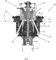
- hub assembly 20 includes an upper shell 21 , a ball screw 22 , a lower shell 23 , a carrier 24 , a pivot link 25 , a pull rod 29 , an optional motor adapter 30 , and an optional motor 31.
- the upper shell 21 and lower shell 23 stabilize and hold ball screw 22 and together form a cavity 32 to receive carrier 24.
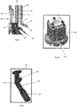
- the carrier 24 a side perspective view of which is shown in FIG. 10 , is connected to end 29' of pull rod 29 , preferably pivotably connected at articulating connection 24' to pull rod 29.
- Ball screw 22 has external threads and carrier 24 has internal threads, and in operation carrier 24 translates or moves along screw 22 and within cavity 32.
- movement or translation of carrier 24 moves pull rod 29 , and more specifically laterally moves articulating connector 29' of pull rod 29 , and pivots or rotates pull rod 29.
- the other articulating end 29" of pull rod 29 connects, preferably pivotably connects, to pivot link 25 at articulating connection 27.
- the pivoting connection of pull rod 29 to carrier 24 at articulating connection 24' , and the pivoting connection of pull rod 29 to pivot link 25 at articulating connection end 27 of the pivot link 25 preferably uses a pin to connect the various members together while allowing articulating movement, rotation and or pivotable motion. While a pin connection is often used in the support structure 10 to connect two members together while permitting pivotable or rotational movement between two members, it is contemplated that other joint connection structures and assemblies may be used to pivotably connect two members together.
- Pivot link 25 is an angulated member that has a mid-connection portion 25' , a connection end 27 , a projection connection portion 28 , and drive strut connection end 25".
- Mid-connection portion 25' connects, preferably pivotably connects, to lower shell 23 by use of a pin. Movement of pull rod 29 pulls on connection end 27 of pivot link 25 to pivot or rotate pivot link 25 to unfold or fold support structure 10.
- optional motor 31 is connected to screw 22 within the space provided by motor adapter 30.
- Optional motor 31 rotates screw 22 to move and translate carrier 24 within cavity 32 , to apply a force to and move, e.g., rotate, pivot link 25.
- FIGS. 7 and 9 illustrate the relative positions of the carrier 24 , the pivot link 25 , and the pull rod 29 when the reflector support structure (and reflector antenna) is in its folded (collapsed position), and FIG. 8 illustrates the carrier 24 , pivot link 25 , and pull rod 29 when the reflector support structure 10 is in the fully expanded (unfolded) position.
- the drive strut assembly 50 attaches to, preferably fixedly connects to, the pivot link 25, and extends from the pivot link 25 as shown in FIG. 9 .
- the drive strut assembly 50 forms an angle x with a horizontal line through the hub assembly 20 as shown in FIGS.
- the angle x changes as the reflector antenna moves from its folded configuration or mode to its unfolded (expanded) configuration or mode.
- the angle x is substantially 90 degrees and the folded drive strut assembly 50 extends in a substantially vertical position, i.e., the drive strut assembly 50 extends upward along the upper shell 21 of the hub assembly 20 and along the hub tower 38.
- the angle x in an embodiment, is about 45 degrees, preferably about 44 degrees, although other angles, geometric orientations, and ranges or angular motion of the pivot link 25 and drive strut assembly 50 with respect to the hub assembly 20 and hub tower 38 are contemplated.
- the carrier stop 24 rises toward and into the upper cavity portion 32' created and surrounded by upper shell 21 , which pulls end 29' of the pull rod 29 up, which in response draws end 27 of the pivot link 25 in toward shell 23 , which in turn rotates or pivots the pivot link 25 about mid-connection 25' , so that it angulates from the first position shown in FIG. 7 to its second angular position shown in FIG. 8 .
- the carrier 24 moving up along the ball screw 22 rotates or pivots the pivot link 25 on lower shell 23 of the hub assembly 20 to deploy, unfold and expand the drive strut assembly 50 , and the drive strut assembly 50 in response applies a force on the rib hinge assembly 60 and/or the rib assembly 40 to unfold the rib assembly 40 to expand the foldable reflector 5.
- Hub tower 38 extends vertically upward from one end of hub assembly 20 as shown in FIG. 12 .
- Pivot ring 35 has a plurality of connectors 36 to connect the rib assemblies 40 to the hub tower 38.
- the connectors 36 are preferably fixedly connected to the pivot ring 35.
- the connectors 36 are preferably articulating connectors that connect the rib assembly to the hub tower 38, and more specifically the pivot ring 35 in a manner to permit the rib assembly 40 to rotate and pivot with respect to the hub tower 38 , and more specifically the pivot ring 35 , so that the rib assembly 40 (explained in greater detail below) can unfold and expand.
- the hub tower 38 optionally has restraint plane brackets 37 and 39 that are small radial arms on the hub tower 38 that support the rib assembly 40 in the stored position.
- Optional pin pullers 33 may interact with the restraint plane brackets 37 and 39 to facilitate holding the rib assemblies 40 in position, e.g., lock the rib assemblies 40 to the brackets 37 , 39 and the hub tower 38. Pin pullers may be released to permit the plurality of rib assemblies 40 to deploy.
- the drive strut assembly 50 is illustrated in FIGS. 14-17.
- FIG. 14 shows the drive strut assembly in the folded condition.
- the drive strut assembly 50 includes an inner drive strut 52 , an outer drive strut 56 , and a drive strut hinge assembly 55 that connects inner drive strut 52 to outer drive strut 56 , preferably provides an articulating connection that permits inner drive strut 52 to pivot with respect to outer drive strut 56.
- the drive strut hinge assembly 55 as shown in FIG. 15 includes an inner drive strut fitting 53 and an outer drive strut fitting 54 which are connected by a pin to permit inner drive strut fitting 53 to pivot and rotate with respect to outer drive strut fitting 54.
- the drive strut hinge 55 preferably permits rotation about one axis, e.g., about an axis through the pin. Although a pin connection is shown for drive strut hinge assembly 55 it will be appreciated that other connection (e.g., hinge) configurations and joints can be utilized.
- the drive strut hinge assembly 55 permits the inner drive strut 52 to pivot or rotate with respect to outer drive strut 56 so that the drive strut assembly 50 can fold (collapse) and unfold (expand) as shown in FIGS. 14-16 .
- the inner drive strut during expansion of the foldable reflector from the fully collapsed and folded position as shown in FIG. 14 to the fully expanded position as shown in FIG. 16 preferably pivots or rotates approximately 180 degrees. Other ranges of rotation are contemplated depending upon the support structure design and configuration.
- An optional stop 54' can be provided on outer drive strut fitting 54 that interfaces with inner drive strut fitting 53 to limit motion, i.e., rotation, of the drive strut hinge assembly 55.
- the optional stop 54' may be adjustable so the amount of rotation of the drive strut hinge can be adjusted.
- the inner drive strut 52 connects, preferably fixedly connects, to the hub assembly 20 , and more specifically connects to the pivot link 25 via connector 51 as shown in FIG. 9 .
- Outer drive strut fitting 78 connects, preferably fixedly connects, to end 58 of the outer drive strut 56 as shown in FIG. 17 .
- Outer drive strut fitting 78 connects to rib assembly 40 , and more specifically to rib hinge assembly 60 of the rib assembly 40.
- Outer drive strut fitting 78 is an angulated member as shown in FIG. 17 and as discussed in more detail below. As illustrated in FIGS.
- outer drive strut 56 may comprise a plurality of members, and in the embodiment illustrated comprises two elongated support members where outer drive strut fitting 78 and drive strut hinge assembly 55 are configured and adapted to interface with the two elongated support members.
- Inner drive strut 52 is shown and illustrated as being a single member (tubular rod), but as can be appreciated by one of ordinary skill in the art, inner drive strut 52 may comprise one or more structural members.
- Rib assembly 40 shown in FIG. 6 in an embodiment includes inner rib 42 , outer rib 46 and a rib hinge assembly 60 connecting inner rib 42 and outer rib 46.
- Rib hinge assembly 60 discussed in more detail below is a multi-piece hinge that permits inner rib 42 to rotate and pivot with respect to outer rib 46.
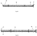
- Inner rib 42 shown in FIG. 18 has a connector 41 at its first end 43 that connects, preferably pivotably connects, the inner rib 42 to the hub tower 38 , and more specifically, connects the pivot ring 35 and the connectors 36 on the pivot ring 35 to the inner rib 42. In operation, the inner rib 42 pivots or rotates from a fully folded position as shown in FIGS.
- inner rib connector 41 is connected to connector 36 by a pin such that inner rib 42 rotates with respect to the hub tower about one axis.
- Other means and joints for connecting inner rib 42 to the hub tower 38 and to pivot ring 35 are contemplated.
- the second end 44 of the inner rib 42 has an inner rib hinge fitting 75 that forms part of rib hinge assembly 60 and functions to connect inner rib 42 to outer rib 46.
- Outer rib 46 shown in FIG. 19 has a connector 62 at its first end 49 that forms part of rib hinge assembly 60 and functions to connect outer rib 46 to inner rib 42.
- Outer rib 46 and inner rib 42 form rib assembly 40.
- inner rib 42 pivots or rotates about 180 degrees with respect to the outer rib 46 from the fully folded position shown in FIGS. 2-3 to the fully expanded position shown in FIGS. 5-6 .
- Rib hinge assembly 60 permits the rotation between inner rib 42 and outer rib 46 , preferably in one plane.
- one of the plurality of rib assemblies 40 may have a larger cross sectional size, shown in FIG. 3 as rib assembly 40' , to facilitate interaction with a boom element (not shown) that holds the reflector in the correct geometry. It is contemplated that all of the rib assembles 40 may have the same cross-sectional thickness.
- One or more rib assemblies 40 may have an optional field joint 45 as shown in FIG. 19 to facilitate connecting to the boom assembly to deploy the reflector antenna 5 in space.
- Rib hinge assembly 60 connects inner rib 42 , outer rib 46 and drive strut assembly 50 , more specifically outer drive strut 56.
- Rib hinge assembly 60 in an embodiment as shown in FIGS. 20-23 can include six support elements and seven articulating joints or connections between the members. The articulating joints may include pins between the connecting elements and may permit rotation in only one plane, however other joints and connection arrangements are contemplated.
- Rib hinge assembly 60 in an embodiment, as shown in FIGS. 20-23 , includes inner rib hinge fitting 75 , hinge frame 70 , outer hinge link 65 , outer rib hinge fitting 62 , inner hinge link 68, and drive strut fitting 78.
- Inner rib hinge fitting 75 has three articulating connection portions 75′ , 75 ⁇ , 75′′′.
- Frame 70 shown in FIG. 23 has three articulating hinge connection portions 70′ , 70 ⁇ , 70′′′
- inner hinge link 68 has two articulating hinge portions 68′ , 68 ⁇
- outer hinge link 65 has two articulating hinge connection portions 65′ , 65 ⁇ .
- Drive strut fitting 78 has two articulating hinge connection portions 78' , 78"
- outer rib hinge fitting 62 has two articulating hinge connections 62' , 62".
- the rib hinge assembly 60 includes inner rib fitting 75 , outer drive strut fitting 78 , outer rib fitting 62 and three intermediate interconnecting members that include frame 70 with three articulating connections, and two linear-shaped, e.g., straight, hinge link members each with two articulating connections.
- first articulating hinge connection 62' of outer rib hinge fitting 62 connects to hinge frame 70 , and more specifically connects to first articulating hinge connection 70' , preferably in a manner that permits frame 70 to pivot or rotate with respect to outer rib hinge fitting 62 , such as, for example, by use of a pin.
- Second articulating hinge connector 62" of outer rib hinge fitting 62 connects to outer hinge link 65 , and more specifically to a first articulating hinge connection 65' of outer hinge link 65 preferably in a manner that permits outer hinge link 65 to pivot or rotate with respect to outer rib hinge fitting 62 , such as for example, by use of a pin.
- Outer hinge link 65 has a second articulating hinge connection 65" that connects to inner rib hinge fitting 75 , and more specifically connects to a first articulating hinge connection 75' of inner rib hinge fitting 75 preferably in a manner that permits outer link 65 to rotate or pivot with respect to inner rib hinge fitting 75 , such as, for example, by use of a pin.
- Frame 70 has a second articulating hinge connection 70" that connects to inner rib hinge fitting 75 , and more specifically connects to second articulating hinge connection 75" of the inner rib hinge 75 preferably in a manner that permits frame 70 to pivot or rotate with respect to inner rib hinge fitting 75 , such as, for example, by use of a pin.
- Frame 70 has a third articulating hinge connection 70′′′ that connect to inner hinge link 68 , and more specifically connects to a first articulating hinge connection 68' of the inner hinge link 68 preferably in a manner that permits inner hinge link 68 to rotate or pivot with respect to frame 70 , such as, for example, by use of a pin.
- Inner hinge link 68 has a second articulating hinge connection 68" that connects to drive strut fitting 78 , and more specifically to a first articulating hinge connection 78' of the drive strut fitting 78 preferably in a manner that permits the inner hinge link 68 to rotate or pivot with respect to the drive strut fitting 78 , such as, for example, by use of a pin.
- Inner rib hinge fitting 75 has a third articulating hinge connection 75′′′ that connects to drive strut fitting 78 , more specifically connects to second articulating hinge connection 78" of the drive strut fitting 78 preferably in a manner that permits the drive strut fitting 78 to rotate or pivot with respects to the inner rib hinge fitting 75 , such as, for example, by use of a pin.
- Frame 70 further includes a stop 82 that in the unfolded, fully expanded position contacts with the inner rib hinge fitting 75 as shown in FIG. 20 .
- hub assembly 20 applies a force, e.g, a torque or moment, to the drive strut assemblies 50 that moves, e.g., pivots or rotates the inner drive strut 52 with respect to the outer drive strut 56 to apply a force through outer drive strut fitting 78 to hinge assembly 60 , which in response unfolds or collapses the rib assembly 40.
- a force e.g, a torque or moment
- the force applied by the outer drive strut fitting 78 acts upon the inner rib fitting 75 and the inner rib 42 through articulating connections, and acts upon the outer rib fitting 62 and outer rib 46 through articulating connections to expand or collapse the inner rib 42 with respect to the outer rib 46.
- Deployable standoff (DPSO) 85 is a support assembly that holds or stands the reflector off of the rib assembly 40.
- DPSO 85 is connected to the rib assembly 40 and may rotate or pivot with respect to the rib assembly 40 , and more specifically may pivot with respect to the outer rib 46.
- a cable or cord 87 may extend from the rib assembly 40 , more specifically the outer rib 46 via a connector 86 , to the DPSO 85.
- the optional cable or cord 87 extending to DPSO from the rib assembly 40 in an embodiment is part of cable system 90.
- the DPSO assembly 85 as shown in FIG. 3 may comprise a pair of support members 88 and connector member 89. It is contemplated that DPSO 85 can comprise a single support member, or more than two support members 88.
- FIG. 24 shows a portion or a panel 6 of reflector 7.
- Surface 8 of the panel 6 is formed of a mesh material 12 , preferably a highly conductive material.
- Multiple panels 6 may be used to form reflector 7 , and in the illustrated embodiment eight ( 8 ) panels 6 may be used and supported by support structure 10 to form reflector 7.
- the panel 6 and the reflector 7 is optionally supported by a series of cables or cords.
- the series of cables and cords supporting and/or restraining the panel 6 of the reflector 7 includes one or more trusses 15.
- the trusses 15 in an embodiment include one or more front cords 16 , one or more rear cords 17 , one or more surface ties 18 , and one or more edge ties 19.
- the front cords 16 are connected to the panel 6 and surface ties 18 and edge ties 19 extend downward and connect to the rear cords 17 of the trusses 15.
- the rear most or outermost front cord 16 forms the outer edge 13 of the panel 6 and is also referred to as the front outboard intercostal cord.
- the panel 6 may also include outer strip cords 11 along the side edges and a center patch cord 14.
- the front cord 16 of the panel closest to the center of the reflector is referred to as the inboard costal, and the center of the panel may have a center patch cord 14.
- the outer most edge tie 19 may form the DPSO cord 87.
- the support structure or frame 10 may comprise thermoelastically stable graphite composite members, including thermoelastically stable graphite composite drive strut assemblies, rib assemblies, hub tower, and DPSO. Other materials are contemplated for the construction of the various components that make up the support structure.
- Reflector support system 10 may further include in an embodiment a cable or cord system 90 that in an embodiment may be configured to restrain expansion of the support structure 10 , including restraining the expansion of rib assembly 40 and drive strut assembly 50.
- An embodiment of optional cable system 90 is shown in FIG. 25 .
- optional cable system 90 may include one or more of tower cords 92 , hinge cross cords 94 , rib tip hoop cords 95 , and rib hinge hoop cords 96. Other cords in addition to or as an alternative may be used in the reflector antenna 5.
- tower cords 92 extend from hub assembly 20 to the tip of the rib assembly 40.
- projection pin 91 connects, preferably pivotably connects, to and extends from portion 28 of pivot link 25 as shown in FIG. 9 .
- Tower cord 92 connects to projection pin 91 and extends to the tip of rib assembly 40 , more specifically to connector 86 on outer rib 46.
- Each rib assembly 40 may have a tower cord 92 , alternate rib assemblies 40 may have a tower cord 92 , or some other arrangement of tower cords 92 may be used.
- Tower cords 92 have slack when the reflector antenna 5 is in the folded or collapsed configuration (condition), but are taunt when the reflector antenna is in the fully expanded condition and the rib assembly 40 is fully expanded.
- Optional cord system 90 may include one or more hinge cross cords 94.
- Hinge cross cords 94 extend from the end of the rib assembly, more specifically the connector 86 on outer rib 46 , to the adjacent rib hinge assembly 60.
- the outer rib 46 of each rib assembly 40 may have two hinge cross cords 94 extending to the rib hinge assembly 60 on each rib assembly 40.
- each rib assembly 40 may have only one hinge cross cord 94 extending to one adjacent rib hinge assembly 60.
- Other configurations for hinge cross cords 94 are contemplated.
- Hinge cross cords 94 have slack when the reflector antenna 5 is in the folded or collapsed configuration (condition), but are taunt when the reflector antenna is in the fully expanded condition and the rib assembly is fully expanded.
- Optional cord system 90 may include one or more rib tip hoop cords 95.
- Rib tip hoop cords 95 extend from the end of the rib assembly, more specifically the connector 86 on outer rib 46 , to the end of the adjacent rib assembly 40 , more specifically the connector 86 on the outer rib 46.
- Each rib assembly 40 preferably has two rib tip hoop cords 95 extending to the connectors 86 on the outer rib 46 on each rib assembly 40.
- each rib assembly 40 may have only one rib tip hoop cord 95 extending to one adjacent rib assembly 40.
- Other configurations for rib tip hoop cords 95 are contemplated.
- Rib tip hoop cords 95 have slack when the reflector antenna 5 is in the folded or collapsed configuration (condition), but are taunt when the reflector antenna is in the fully expanded condition and the rib assembly is fully expanded.
- Optional cord system 90 may include one or more rib hinge hoop cords 96.
- Rib hinge hoop cords 96 extend from the rib hinge assembly 60 of a rib assembly 40 to an adjacent rib hinge assembly 60 of an adjacent rib assembly 40.
- Each rib assembly 40 preferably has two rib hinge hoop cords 96 extending to each adjacent rib hinge assembly 60 on each adjacent rib assembly 40.
- each rib assembly 40 may have only one rib hinge hoop cord 96 extending to one adjacent rib hinge assembly 60.
- Other configurations for rib hinge hoop cords 96 are contemplated.
- Rib hinge hoop cords 96 have slack when the reflector antenna 5 is in the folded or collapsed configuration (condition), but are taunt when the reflector antenna is in the fully expanded condition and the rib assembly is fully expanded.
- the support structure 10 permits, facilitates and provides a compact folded configuration for the reflector antenna 5 and also permits, facilitates and provides for controlled expansion of the reflector in a manner that provides no over stretch or undue strain on the support structure, and permits the reflector to unfold in a highly reliable and accurate manner.
- carrier 24 moves laterally about 1.5 inches (3.81 cm) along screw 22 to pivot end 25" of the pivot link 25 about forty-five degrees (45), which unfolds and rotates inner drive strut 52 about 180 degrees with respect to outer drive strut 56 , which rotates the inner rib 42 about ninety degrees (90) with respect to the hub tower 38 and rotates the outer rib 46 about 180 degrees with respect to the inner rib 42.
- Hub assembly 20 may take other configurations and sizes to obtain the desired torque and angulation to the drive strut assembly 50.
- other rotational ranges are contemplated for drive strut assembly 50 and rib assembly 40.
- Other configurations, sizes, shapes, and arrangements for the rib assembly 60 , and its various elements, and interconnections are also contemplated.
- FIG. 26 is an exemplary flowchart in accordance with one embodiment illustrating and describing a method of operating a foldable reflector in accordance with an embodiment of the present disclosure. While method 200 is described for the sake of convenience and not with an intent of limiting the disclosure as comprising a series and/or a number of steps, it is to be understood that the process does not need to be performed as a series of steps and/or the steps do not need to be performed in the order shown and described with respect to FIG. 26 , but the process may be integrated and/or one or more steps may be performed together, simultaneously, or the steps may be performed in the order disclosed or in an alternate order. In this regard, each block in the flowchart or block diagrams may represent a module, segment, or portion of a process, which comprises one or more steps for implementing the specified function(s).
- blocks of the flowchart illustration support combinations of means for performing the specified functions, and/or combinations of steps for performing the specified functions. It will also be understood that each block of the flowchart illustration, and combinations of blocks in the flowchart illustration, can be implemented by the disclosed embodiments and equivalents thereof, including future developed equivalents.
- a screw is rotated, for example in a hub assembly.
- Rotation of the screw, at 220 translates a carrier, preferably along the screw.
- Translation of the carrier, at 230 rotates or pivots a pivot link, preferably in an embodiment about 45 degrees.
- Rotation of the pivot link, at 240 unfolds or folds a drive strut assembly, e.g. preferably rotates an inner drive strut with respect to an outer drive strut.
- the inner drive strut rotates with respect to the outer drive strut an angular range that in an embodiment is preferably about 180 degrees.
- unfolding the drive strut assembly applies a force to the rib assembly, preferably through a rib hinge assembly in the middle region of the drive rib assembly.
- Applying force to the rib assembly at 260 unfolds or folds the rib assembly, preferably unfolds an inner rib with respect to an outer rib an angular range that in an embodiment is preferably about 180 degrees.
- Unfolding or folding the rib assembly, at 280 deploys the reflector.
- unfolding the rib assembly at 270 deploys the DPSO to hold the reflector off the rib assembly.
- the support structure may optionally be restrained by a cable system.
- the reflector has many applications, may be implemented in various manners and, as such is not to be limited by the foregoing embodiments and examples.
- the support structure may be varied and the locations and positions of particular elements, for example, may be altered. Alternate embodiments are possible that have features in addition to those described herein or may have less than all the features described. Functionality may also be, in whole or in part, distributed among multiple components, in manners now known or to become known.
Landscapes
- Physics & Mathematics (AREA)
- Engineering & Computer Science (AREA)
- Electromagnetism (AREA)
- Architecture (AREA)
- Astronomy & Astrophysics (AREA)
- General Physics & Mathematics (AREA)
- Remote Sensing (AREA)
- Civil Engineering (AREA)
- Structural Engineering (AREA)
- Aviation & Aerospace Engineering (AREA)
- Aerials With Secondary Devices (AREA)
- Details Of Aerials (AREA)
Claims (9)
- Une structure de support de réflecteur d'antenne pliable et extensible (10) pour supporter un réflecteur extensible généralement en forme d'assiette (7), la structure de support de réflecteur (10) comprenant:un ensemble de moyeu (20) pour fournir une force à la structure de support (10);une tour de moyeu (38) s'étendant depuis l'ensemble de moyeu (20);une pluralité d'ensembles de jambe de force d'entraînement (50), chaque ensemble de jambe de force d'entraînement (50) ayant une jambe de force d'entraînement interne (52), une jambe de force d'entraînement externe (56) et un ensemble de charnière de jambe de force (55) de sorte que la jambe de force d'entraînement interne (52) peut pivoter par rapport à la jambe de force d'entraînement externe (56) de sorte que chaque ensemble de jambe de force d'entraînement (50) peut se plier ou s'étendre, et au moins un ensemble de jambe de force d'entraînement (50) est relié à l'ensemble de moyeu (20) et est configurable pour recevoir une force de l'ensemble de moyeu (20); etune pluralité d'ensembles de nervures (40), chaque ensemble de nervures (40) ayant une nervure intérieure (42), une nervure extérieure (46), et un ensemble de charnière de nervure en plusieurs parties (60) de sorte que la nervure intérieure (42) peut pivoter par rapport à la nervure extérieure (46), et chaque nervure intérieure (42) est connectée de manière pivotante à la tour de moyeu (38),dans laquelle la structure de support (10) a une première configuration pliée et une seconde configuration étendue et chaque ensemble d'entretoise d'entraînement (50) est connecté de manière pivotante à l'un des ensembles de nervures (40) et est configuré pour appliquer une force à cet ensemble de nervures (40) pour faire tourner la nervure extérieure (46) par rapport à la nervure intérieure (42) en réponse à l'ensemble de moyeu (20) appliquant la force à l'au moins un des ensembles d'entretoise d'entraînement (50) pour ainsi plier ou étendre la structure de support de réflecteur (10) de la première configuration pliée à la seconde configuration étendue, caractérisé en ce quel'entretoise d'entraînement intérieure (52) est configurée pour tourner d'environ 180 degrés par rapport à l'entretoise d'entraînement extérieure (56) et, en réponse, la nervure extérieure (46) est configurée pour tourner d'environ 180 degrés par rapport à la nervure intérieure (42).
- La structure de support de réflecteur (10) selon la revendication 1, dans laquelle l'ensemble charnière de nervure (60) comprend un raccord de nervure interne (75), un raccord de nervure externe (62) et un raccord d'entretoise d'entraînement externe (78).
- La structure de support de réflecteur (10) selon la revendication 2, dans laquelle le raccord de jambe de force d'entraînement externe (78) a une pluralité de connexions articulées.
- La structure de support de réflecteur (10) selon la revendication 2, dans laquelle le raccord de nervure interne (75) a trois connexions d'articulation.
- La structure de support de réflecteur (10) selon la revendication 2, dans laquelle l'ensemble de charnière de nervure (60) comprend un lien de charnière interne (68) et des éléments intermédiaires supplémentaires et le raccord de jambe de force d'entra nement externe (78) se connecte au raccord de nervure interne (75) et au lien de charnière interne (68).
- La structure de support de réflecteur (10) selon la revendication 1, dans laquelle l'ensemble de charnière de nervure (60) comprend six composants avec sept connexions articulées, dans laquelle les six composants comprennent un raccord de charnière de nervure interne (75), un cadre de charnière (70), une liaison de charnière externe (65), un raccord de charnière de nervure externe (62), une liaison de charnière interne (68) et un raccord d'entretoise d'entra nement (78).
- La structure de support de réflecteur (10) selon la revendication 1, dans laquelle la structure de support (10) comprend en outre au moins une distance de sécurité déployable, DPSO, (85).
- La structure de support de réflecteur (10) selon la revendication 1, dans laquelle la structure de support (10) comprend en outre un système de câbles (90) pour retenir la structure de support de réflecteur (10).
- La structure de support de réflecteur (10) selon la revendication 1, dans laquelle l'ensemble de moyeu (20) comprend un support (24), une tige de traction (29) et une liaison pivot (25).
Applications Claiming Priority (1)
| Application Number | Priority Date | Filing Date | Title |
|---|---|---|---|
| US16/107,853 US10707552B2 (en) | 2018-08-21 | 2018-08-21 | Folded rib truss structure for reflector antenna with zero over stretch |
Publications (2)
| Publication Number | Publication Date |
|---|---|
| EP3614487A1 EP3614487A1 (fr) | 2020-02-26 |
| EP3614487B1 true EP3614487B1 (fr) | 2021-11-24 |
Family
ID=67659243
Family Applications (1)
| Application Number | Title | Priority Date | Filing Date |
|---|---|---|---|
| EP19192249.1A Active EP3614487B1 (fr) | 2018-08-21 | 2019-08-19 | Structure de support de fissure pliée pour antenne de réflecteur à zéro sur-étirement |
Country Status (2)
| Country | Link |
|---|---|
| US (1) | US10707552B2 (fr) |
| EP (1) | EP3614487B1 (fr) |
Families Citing this family (13)
| Publication number | Priority date | Publication date | Assignee | Title |
|---|---|---|---|---|
| CN109860972B (zh) * | 2018-12-19 | 2019-12-10 | 燕山大学 | 一种基于对称结构四面体组合单元的模块化可展天线机构 |
| EP4024606B1 (fr) * | 2019-09-24 | 2023-07-12 | Airbus Defence and Space, S.A. | Ensemble dépliable pour antennes |
| CN112531349B (zh) * | 2020-11-27 | 2022-02-08 | 中国科学院空天信息创新研究院 | 一种天线展开机构 |
| CN112968301B (zh) * | 2021-02-03 | 2023-06-20 | 深圳航天东方红卫星有限公司 | 一种弹簧机构驱动绳轮传动的可折展星载八木天线 |
| CN113381161B (zh) * | 2021-05-24 | 2022-08-23 | 西安电子科技大学 | 一种可重复展收的单折伞天线展开机构 |
| TR2021017100A1 (tr) * | 2021-11-03 | 2023-05-22 | Aselsan Elektronik Sanayi Ve Ticaret As | Tümleşi̇k anten mekani̇zmasi |
| CN114039213B (zh) * | 2021-11-03 | 2022-06-24 | 安徽大学 | 过约束四棱锥模块化抛物柱面天线可展开机构 |
| CN114336008B (zh) * | 2021-12-07 | 2023-12-29 | 中国电子科技集团公司第五十四研究所 | 通信设备 |
| CN114530682B (zh) * | 2022-01-25 | 2023-11-07 | 江苏捷诚车载电子信息工程有限公司 | 移动式天线展开装置及使用方法 |
| CN114696060B (zh) * | 2022-04-26 | 2023-06-30 | 中国电子科技集团公司第三十八研究所 | 同步定位展收式雷达天线骨架 |
| CN217468802U (zh) * | 2022-05-30 | 2022-09-20 | 中兴通讯股份有限公司 | 终端天线及终端设备 |
| CN115275559B (zh) * | 2022-07-22 | 2024-07-09 | 西安空间无线电技术研究所 | 一种提高大口径正馈式构架天线刚度的可展支撑机构 |
| US12142833B2 (en) * | 2022-11-07 | 2024-11-12 | Eagle Technology, Llc | Scissors radial deployable antenna reflector structure |
Citations (1)
| Publication number | Priority date | Publication date | Assignee | Title |
|---|---|---|---|---|
| EP0807991B1 (fr) * | 1996-05-15 | 2000-07-12 | Trw Inc. | Réflecteur téléscopique déployable pour antenne et procédé de déploiement du réflecteur |
Family Cites Families (118)
| Publication number | Priority date | Publication date | Assignee | Title |
|---|---|---|---|---|
| US4030102A (en) | 1975-10-23 | 1977-06-14 | Grumman Aerospace Corporation | Deployable reflector structure |
| US4989015A (en) | 1987-10-26 | 1991-01-29 | Hughes Aircraft Company | Unfurlable mesh reflector |
| US6133570A (en) | 1994-03-15 | 2000-10-17 | Lockheed Martin Corporation | Semiconductor photovoltaic diffractive resonant optical cavity infrared detector |
| US5579021A (en) | 1995-03-17 | 1996-11-26 | Hughes Aircraft Company | Scanned antenna system |
| US5714179A (en) | 1995-10-30 | 1998-02-03 | The Boeing Company | Rigid tooling with compliant forming surface for forming parts from composite materials |
| US5666128A (en) | 1996-03-26 | 1997-09-09 | Lockheed Martin Corp. | Modular supertile array antenna |
| US5870060A (en) | 1996-05-01 | 1999-02-09 | Trw Inc. | Feeder link antenna |
| US5818395A (en) | 1997-01-16 | 1998-10-06 | Trw Inc. | Ultralight collapsible and deployable waveguide lens antenna system |
| US5969695A (en) | 1997-07-07 | 1999-10-19 | Hughes Electronics Corporation | Mesh tensioning, retention and management systems for large deployable reflectors |
| US5947590A (en) | 1997-09-15 | 1999-09-07 | Hughes-Jvc Technology Corporation | High power arc lamp reflector with shroud and plurality of cooling fins on exterior surface of reflector for image projector |
| US5912741A (en) | 1997-10-10 | 1999-06-15 | Northrop Grumman Corporation | Imaging scatterometer |
| DE19817766A1 (de) | 1998-04-21 | 1999-11-11 | Daimler Chrysler Ag | Zentral gespeistes Antennensystem und Verfahren zum Optimieren eines solchen Antennensystems |
| US6104358A (en) | 1998-05-12 | 2000-08-15 | Trw Inc. | Low cost deployable reflector |
| US6028570A (en) | 1998-05-18 | 2000-02-22 | Trw Inc. | Folding perimeter truss reflector |
| US6043425A (en) | 1998-10-02 | 2000-03-28 | Hughes Electronics Corporation | Solar power source with textured solar concentrator |
| US6094175A (en) | 1998-11-17 | 2000-07-25 | Hughes Electronics Corporation | Omni directional antenna |
| US6081244A (en) | 1998-12-14 | 2000-06-27 | Space Systems/Loral, Inc. | Method and apparatus for an unfurlable isometric antenna reflector |
| US6018328A (en) | 1998-12-17 | 2000-01-25 | Hughes Electronics Corporation | Self-forming rib reflector |
| US6154522A (en) | 1999-02-11 | 2000-11-28 | Mcdonnell Douglas Corporation | Method, system and apparatus for aiming a device emitting a radiant beam |
| US6172655B1 (en) | 1999-02-12 | 2001-01-09 | Lockheed Martin Corporation | Ultra-short helical antenna and array thereof |
| US6243053B1 (en) | 1999-03-02 | 2001-06-05 | Trw Inc. | Deployable large antenna reflector structure |
| US6297511B1 (en) | 1999-04-01 | 2001-10-02 | Raytheon Company | High frequency infrared emitter |
| US6191757B1 (en) | 1999-04-08 | 2001-02-20 | Hughes Electronics Corporation | System for compact stowage of segmented dish reflectors |
| US6189835B1 (en) | 1999-04-30 | 2001-02-20 | Hughes Electronics Corporation | Apparatus for spacecraft angular momentum control through the use of reflective thermal blankets |
| US6307194B1 (en) | 1999-06-07 | 2001-10-23 | The Boeing Company | Pixel structure having a bolometer with spaced apart absorber and transducer layers and an associated fabrication method |
| US6618025B2 (en) | 1999-06-11 | 2003-09-09 | Harris Corporation | Lightweight, compactly deployable support structure with telescoping members |
| US6313811B1 (en) | 1999-06-11 | 2001-11-06 | Harris Corporation | Lightweight, compactly deployable support structure |
| US6377183B1 (en) | 1999-06-17 | 2002-04-23 | The Boeing Company | Smoke detector having a moisture compensating device |
| US6219003B1 (en) | 1999-07-01 | 2001-04-17 | Trw Inc. | Resistive taper for dense packed feeds for cellular spot beam satellite coverage |
| US6137454A (en) | 1999-09-08 | 2000-10-24 | Space Systems/Loral, Inc. | Unfurlable sparse array reflector system |
| US6290180B1 (en) | 1999-09-09 | 2001-09-18 | Lockheed Martin Corporation | Photocatalytic coatings on optical solar reflectors to decompose organic contaminants |
| US6285332B1 (en) | 1999-09-10 | 2001-09-04 | Trw Inc. | Frequency selective reflector |
| US6278416B1 (en) | 1999-11-18 | 2001-08-21 | Harris Corporation | Surface edge enhancement for space-deployable mesh antenna |
| US6208317B1 (en) | 2000-02-15 | 2001-03-27 | Hughes Electronics Corporation | Hub mounted bending beam for shape adjustment of springback reflectors |
| US6445343B1 (en) | 2000-02-16 | 2002-09-03 | Hughes Electronics Corporation | Antenna element array alignment system |
| US6621461B1 (en) | 2000-08-09 | 2003-09-16 | Hughes Electronics Corporation | Gridded reflector antenna |
| US6366257B1 (en) | 2000-11-15 | 2002-04-02 | The Boeing Company | Integrated dual beam reflector antenna |
| US6621459B2 (en) | 2001-02-02 | 2003-09-16 | Raytheon Company | Plasma controlled antenna |
| US6515636B2 (en) | 2001-04-12 | 2003-02-04 | Lockheed Martin Corporation | Active array antenna with flexible membrane elements and tensioning arrangement |
| US6542132B2 (en) | 2001-06-12 | 2003-04-01 | Harris Corporation | Deployable reflector antenna with tensegrity support architecture and associated methods |
| US6768468B2 (en) | 2001-09-27 | 2004-07-27 | Raytheon Company | Reflecting surfaces having geometries independent of geometries of wavefronts reflected therefrom |
| US7129903B2 (en) | 2001-09-27 | 2006-10-31 | The Boeing Company | Method and apparatus for mounting a rotating reflector antenna to minimize swept arc |
| FR2830625B1 (fr) | 2001-10-08 | 2004-02-13 | Cit Alcatel | Reflecteur optique de surface, pour un engin spatial tel qu'un satellite geostationnaire |
| US6542129B1 (en) | 2001-10-12 | 2003-04-01 | The Boeing Company | Elevation positioning cradle for microwave antenna |
| US6611238B1 (en) | 2001-11-06 | 2003-08-26 | Hughes Electronics Corporation | Method and apparatus for reducing earth station interference from non-GSO and terrestrial sources |
| US6570528B1 (en) | 2001-11-09 | 2003-05-27 | The Boeing Company | Antenna system for multiple orbits and multiple areas |
| US6608607B2 (en) | 2001-11-27 | 2003-08-19 | Northrop Grumman Corporation | High performance multi-band frequency selective reflector with equal beam coverage |
| US6642905B2 (en) | 2001-12-21 | 2003-11-04 | The Boeing Company | Thermal-locate 5W(V) and 5W(H) SSPA's on back of reflector(s) |
| US7110716B2 (en) | 2002-01-30 | 2006-09-19 | The Boeing Company | Dual-band multiple beam antenna system for communication satellites |
| US7024158B2 (en) | 2002-04-25 | 2006-04-04 | Northrop Grumman Corporation | Broadband communication satellite |
| EP1386838B1 (fr) | 2002-07-31 | 2006-05-17 | EADS Astrium GmbH | Réflecteur d'antenne déployable |
| JP2004146898A (ja) | 2002-10-22 | 2004-05-20 | Nec Toshiba Space Systems Ltd | 展開型メッシュアンテナ |
| US6775046B2 (en) | 2002-11-06 | 2004-08-10 | Northrop Grumman Corporation | Thin film shape memory alloy reflector |
| US6859188B1 (en) | 2003-03-27 | 2005-02-22 | Lockheed Martin Corporation | Rotationally configurable offset reflector antenna |
| US6882323B2 (en) | 2003-05-09 | 2005-04-19 | Northrop Grumman Corporation | Multi-beam antenna system with shaped reflector for generating flat beams |
| US7104506B1 (en) | 2003-08-06 | 2006-09-12 | Lockheed Martin Corporation | Spacecraft disturbance trimming system |
| US7216995B2 (en) | 2003-09-10 | 2007-05-15 | Nippon Telegraph And Telephone Corporation | Deployable reflector |
| US7034771B2 (en) | 2003-09-10 | 2006-04-25 | The Boeing Company | Multi-beam and multi-band antenna system for communication satellites |
| US6975282B2 (en) | 2003-09-16 | 2005-12-13 | Northrop Grumman Corporation | Integrated symmetrical reflector and boom |
| US7119480B2 (en) | 2003-09-24 | 2006-10-10 | The Boeing Company | Ventilated reflector |
| US6919863B2 (en) | 2003-10-06 | 2005-07-19 | Northrop Grumman Corporation | Integrated reflector and boom |
| US7498549B2 (en) | 2003-10-24 | 2009-03-03 | Raytheon Company | Selective layer millimeter-wave surface-heating system and method |
| US6937203B2 (en) | 2003-11-14 | 2005-08-30 | The Boeing Company | Multi-band antenna system supporting multiple communication services |
| US7009578B2 (en) | 2003-11-17 | 2006-03-07 | The Boeing Company | Deployable antenna with foldable resilient members |
| US7126477B2 (en) | 2004-01-15 | 2006-10-24 | Raytheon Company | Millimeter-wave area-protection system and method |
| US7382743B1 (en) | 2004-08-06 | 2008-06-03 | Lockheed Martin Corporation | Multiple-beam antenna system using hybrid frequency-reuse scheme |
| US7345653B2 (en) | 2005-01-31 | 2008-03-18 | The Boeing Company | Shaped reflector reoptimization |
| FR2882490B1 (fr) | 2005-02-23 | 2009-04-24 | Eads Space Transp Sas Soc Par | Procede pour la realisation de motifs electriquement conducteurs sur une surface non developpable d'un substrat isolant, et dispositif obtenu |
| FR2882491B1 (fr) | 2005-02-23 | 2009-04-24 | Eads Space Transp Sas Soc Par | Procede pour former des motifs electriquement conducteurs sur une surface non developpable d'un substrat isolant, et dispositif obtenu |
| US7379191B2 (en) | 2005-05-20 | 2008-05-27 | The Boeing Company | Optical MEMS wavefront diagnostic transceivers and receiver |
| US7737903B1 (en) | 2005-06-27 | 2010-06-15 | Lockheed Martin Corporation | Stepped-reflector antenna for satellite communication payloads |
| FR2888674B1 (fr) | 2005-07-13 | 2009-10-23 | Alcatel Sa | Antenne reseau a reflecteur(s) conforme(s), a forte reconfigurabilite en orbite |
| US7920100B2 (en) | 2005-08-18 | 2011-04-05 | Raytheon Company | Foldable reflect array |
| US7490538B2 (en) | 2005-08-18 | 2009-02-17 | Raytheon Company | Weapon having lethal and non-lethal directed-energy portions |
| US7784390B1 (en) | 2005-08-18 | 2010-08-31 | Raytheon Company | Solid-state non-lethal directed energy weapon |
| US7443573B2 (en) | 2005-09-20 | 2008-10-28 | Raytheon Company | Spatially-fed high-power amplifier with shaped reflectors |
| FR2893478B1 (fr) | 2005-11-14 | 2011-05-20 | Eads Space Transp Sas | Circuit imprime a surface non developpable a trois dimensions et son procede de fabrication. |
| US7494255B2 (en) | 2005-11-16 | 2009-02-24 | The Boeing Company | Ceiling illumination for aircraft interiors |
| US7710340B2 (en) | 2006-01-13 | 2010-05-04 | Lockheed Martin Corporation | Reconfigurable payload using non-focused reflector antenna for HIEO and GEO satellites |
| US8354956B2 (en) | 2006-01-13 | 2013-01-15 | Lockheed Martin Corporation | Space segment payload architecture for mobile satellite services (MSS) systems |
| US7570226B2 (en) | 2006-02-28 | 2009-08-04 | The Boeing Company | Method and apparatus for grating lobe control in faceted mesh reflectors |
| US7595769B2 (en) | 2006-02-28 | 2009-09-29 | The Boeing Company | Arbitrarily shaped deployable mesh reflectors |
| US7751779B2 (en) | 2006-12-21 | 2010-07-06 | Northrop Grumman Space & Mission Systems Corp. | Satellite communication system |
| US7705796B2 (en) | 2007-06-27 | 2010-04-27 | The Boeing Company | Dual offset reflector system utilizing at least one gimbal mechanism |
| DE102007036492B4 (de) | 2007-08-01 | 2009-07-30 | Trw Automotive Electronics & Components Gmbh & Co. Kg | Optische Sensorvorrichtung |
| US7686255B2 (en) | 2007-08-28 | 2010-03-30 | Raytheon Company | Space vehicle having a payload-centric configuration |
| DE102007044074B4 (de) | 2007-09-14 | 2011-05-26 | Thales Electron Devices Gmbh | Elektrostatische Ionenbeschleunigeranordnung |
| US7675456B2 (en) | 2007-10-11 | 2010-03-09 | Northrop Grumman Corporation | Technique for mitigating multipath impacts on azimuth accuracy in a monopulse interrogator |
| DE102008020171B4 (de) | 2008-04-22 | 2010-08-05 | Trw Automotive Electronics & Components Gmbh | Optische Sensorvorrichtung |
| FR2933782B1 (fr) | 2008-07-11 | 2010-08-13 | Thales Sa | Dispositif de correction des defauts optiques d'un miroir de telescope |
| US9190716B2 (en) | 2008-09-05 | 2015-11-17 | Astrium Limited | Reflector |
| US8462067B2 (en) | 2008-10-08 | 2013-06-11 | Astrium Limited | Apparatus for an antenna system |
| US8568100B2 (en) | 2008-12-09 | 2013-10-29 | The Boeing Company | Bi-axial compliant bearing |
| US9281569B2 (en) | 2009-01-29 | 2016-03-08 | Composite Technology Development, Inc. | Deployable reflector |
| ES2652121T3 (es) | 2009-05-18 | 2018-01-31 | Airbus Defence And Space, S.A. | Procedimiento para mejorar la reflectividad de superficies reflectoras de antenas |
| FR2947103B1 (fr) | 2009-06-19 | 2012-05-18 | Thales Sa | Antenne a flexibilite de mission, satellite comportant une telle antenne et procede de commande du changement de mission d'une telle antenne |
| US8253620B2 (en) | 2009-07-23 | 2012-08-28 | Northrop Grumman Systems Corporation | Synthesized aperture three-dimensional radar imaging |
| FR2952238B1 (fr) | 2009-11-03 | 2012-05-04 | Thales Sa | Montage d'antenne a faisceau mobile |
| US8315557B1 (en) | 2009-12-31 | 2012-11-20 | Lockheed Martin Corporation | Common aperture antenna for multiple contoured beams and multiple spot beams |
| US8508430B2 (en) * | 2010-02-01 | 2013-08-13 | Harris Corporation | Extendable rib reflector |
| FR2957719B1 (fr) | 2010-03-19 | 2013-05-10 | Thales Sa | Antenne reseau reflecteur a compensation de polarisation croisee et procede de realisation d'une telle antenne |
| US8781794B2 (en) | 2010-10-21 | 2014-07-15 | Lockheed Martin Corporation | Methods and systems for creating free space reflective optical surfaces |
| FR2966984B1 (fr) | 2010-10-29 | 2013-08-30 | Thales Sa | Dispositif d'emission d'ondes radioelectriques, antenne et engin spatial. |
| US8905587B1 (en) | 2011-08-09 | 2014-12-09 | The Boeing Company | Internal covert IR filter for searchlight systems |
| US8654033B2 (en) | 2011-09-14 | 2014-02-18 | Harris Corporation | Multi-layer highly RF reflective flexible mesh surface and reflector antenna |
| US8797663B1 (en) | 2011-09-15 | 2014-08-05 | The Boeing Company | Method and apparatus for selective filtering of an illumination device |
| FR2993371B1 (fr) | 2012-07-13 | 2014-08-15 | Thales Sa | Systeme optique de mesure d'orientation et de position sans formation d'image a source ponctuelle et masque |
| US9318808B1 (en) | 2012-08-24 | 2016-04-19 | The Boeing Company | Configurable electromagnetic reflector |
| US9099595B2 (en) | 2012-09-14 | 2015-08-04 | The Boeing Company | Group-IV solar cell structure using group-IV or III-V heterostructures |
| CN102904001A (zh) | 2012-10-26 | 2013-01-30 | 哈尔滨工业大学 | 可折展模块及采用该可折展模块的曲面桁架天线支撑机构 |
| ES2599764T3 (es) | 2012-11-05 | 2017-02-03 | Thales Alenia Space Italia S.P.A. Con Unico Socio | Gran reflector desplegable para una antena de satélite |
| US9337544B2 (en) | 2013-01-07 | 2016-05-10 | Lockheed Martin Corporation | Configurable backing structure for a reflector antenna and corrective synthesis for mechanical adjustment thereof |
| US9381581B1 (en) | 2013-02-27 | 2016-07-05 | The Boeing Company | End mill |
| US9293820B2 (en) | 2013-03-13 | 2016-03-22 | The Boeing Company | Compensating for a non-ideal surface of a reflector in a satellite communication system |
| US9484636B2 (en) | 2014-02-26 | 2016-11-01 | Northrop Grumman Systesms Corportion | Mesh reflector with truss structure |
| US9458987B2 (en) | 2014-08-13 | 2016-10-04 | The Boeing Company | Multi-wavelength light emitting assembly |
| US9608333B1 (en) | 2015-12-07 | 2017-03-28 | Harris Corporation | Scalable high compaction ratio mesh hoop column deployable reflector system |
| US10236590B1 (en) * | 2016-12-21 | 2019-03-19 | The United States Of America, As Represented By The Secretary Of The Air Force | Foldable segmented structure and deployable reflector antenna comprised thereof |
-
2018
- 2018-08-21 US US16/107,853 patent/US10707552B2/en active Active
-
2019
- 2019-08-19 EP EP19192249.1A patent/EP3614487B1/fr active Active
Patent Citations (1)
| Publication number | Priority date | Publication date | Assignee | Title |
|---|---|---|---|---|
| EP0807991B1 (fr) * | 1996-05-15 | 2000-07-12 | Trw Inc. | Réflecteur téléscopique déployable pour antenne et procédé de déploiement du réflecteur |
Also Published As
| Publication number | Publication date |
|---|---|
| EP3614487A1 (fr) | 2020-02-26 |
| US20200067168A1 (en) | 2020-02-27 |
| US10707552B2 (en) | 2020-07-07 |
Similar Documents
| Publication | Publication Date | Title |
|---|---|---|
| EP3614487B1 (fr) | Structure de support de fissure pliée pour antenne de réflecteur à zéro sur-étirement | |
| US6618025B2 (en) | Lightweight, compactly deployable support structure with telescoping members | |
| US4380013A (en) | Expandable panel and truss system/antenna/solar panel | |
| US4557097A (en) | Sequentially deployable maneuverable tetrahedral beam | |
| JP5732656B2 (ja) | 展開式アンテナ | |
| US6313811B1 (en) | Lightweight, compactly deployable support structure | |
| WO2014127813A1 (fr) | Structure de support déployable | |
| CN107482322B (zh) | 一种基于张拉结构的可展开抛物柱面天线 | |
| JP4876941B2 (ja) | 展開型アンテナ | |
| EP2355247A1 (fr) | Réflecteur de nervure extensible | |
| US7782530B1 (en) | Deployable telescope having a thin-film mirror and metering structure | |
| CN112319855A (zh) | 一种用于在轨组装的空间可展棱柱单元 | |
| CN111977030B (zh) | 大折展比太阳翼 | |
| CN111129691B (zh) | 一种基于张拉膜的可展开网状抛物柱面天线 | |
| CN114503361B (zh) | 天线可展开组件 | |
| EP3879626B1 (fr) | Réflecteur spatial déployable | |
| EP3923412B1 (fr) | Systèmes et procédés permettant de fournir des antennes ayant des positions décalés couplés mécaniquement | |
| CN110661075B (zh) | 一种用于超长口径的可伸缩模块化柱面天线 | |
| EP3709436B1 (fr) | Antenne réflecteur à rapport de compactage élevé et à optique décalé | |
| JP3878973B2 (ja) | 展開型骨組構造体 | |
| CN116424572A (zh) | 一种轻量化扇形展开机构及航天器 | |
| US20200354087A1 (en) | Deployment mechanism for reflector antenna system | |
| CN110247150B (zh) | 一种基于主轴的可展开卫星天线桁架结构 | |
| JP2003095199A (ja) | 展開アンテナ | |
| CN114094308A (zh) | 一种可折展的抛物柱面天线 |
Legal Events
| Date | Code | Title | Description |
|---|---|---|---|
| PUAI | Public reference made under article 153(3) epc to a published international application that has entered the european phase |
Free format text: ORIGINAL CODE: 0009012 |
|
| STAA | Information on the status of an ep patent application or granted ep patent |
Free format text: STATUS: REQUEST FOR EXAMINATION WAS MADE |
|
| 17P | Request for examination filed |
Effective date: 20190819 |
|
| AK | Designated contracting states |
Kind code of ref document: A1 Designated state(s): AL AT BE BG CH CY CZ DE DK EE ES FI FR GB GR HR HU IE IS IT LI LT LU LV MC MK MT NL NO PL PT RO RS SE SI SK SM TR |
|
| AX | Request for extension of the european patent |
Extension state: BA ME |
|
| GRAP | Despatch of communication of intention to grant a patent |
Free format text: ORIGINAL CODE: EPIDOSNIGR1 |
|
| STAA | Information on the status of an ep patent application or granted ep patent |
Free format text: STATUS: GRANT OF PATENT IS INTENDED |
|
| INTG | Intention to grant announced |
Effective date: 20210917 |
|
| GRAS | Grant fee paid |
Free format text: ORIGINAL CODE: EPIDOSNIGR3 |
|
| GRAA | (expected) grant |
Free format text: ORIGINAL CODE: 0009210 |
|
| STAA | Information on the status of an ep patent application or granted ep patent |
Free format text: STATUS: THE PATENT HAS BEEN GRANTED |
|
| AK | Designated contracting states |
Kind code of ref document: B1 Designated state(s): AL AT BE BG CH CY CZ DE DK EE ES FI FR GB GR HR HU IE IS IT LI LT LU LV MC MK MT NL NO PL PT RO RS SE SI SK SM TR |
|
| REG | Reference to a national code |
Ref country code: GB Ref legal event code: FG4D |
|
| REG | Reference to a national code |
Ref country code: DE Ref legal event code: R096 Ref document number: 602019009481 Country of ref document: DE |
|
| REG | Reference to a national code |
Ref country code: AT Ref legal event code: REF Ref document number: 1450562 Country of ref document: AT Kind code of ref document: T Effective date: 20211215 |
|
| REG | Reference to a national code |
Ref country code: IE Ref legal event code: FG4D |
|
| REG | Reference to a national code |
Ref country code: LT Ref legal event code: MG9D |
|
| REG | Reference to a national code |
Ref country code: NL Ref legal event code: MP Effective date: 20211124 |
|
| REG | Reference to a national code |
Ref country code: AT Ref legal event code: MK05 Ref document number: 1450562 Country of ref document: AT Kind code of ref document: T Effective date: 20211124 |
|
| PG25 | Lapsed in a contracting state [announced via postgrant information from national office to epo] |
Ref country code: RS Free format text: LAPSE BECAUSE OF FAILURE TO SUBMIT A TRANSLATION OF THE DESCRIPTION OR TO PAY THE FEE WITHIN THE PRESCRIBED TIME-LIMIT Effective date: 20211124 Ref country code: LT Free format text: LAPSE BECAUSE OF FAILURE TO SUBMIT A TRANSLATION OF THE DESCRIPTION OR TO PAY THE FEE WITHIN THE PRESCRIBED TIME-LIMIT Effective date: 20211124 Ref country code: FI Free format text: LAPSE BECAUSE OF FAILURE TO SUBMIT A TRANSLATION OF THE DESCRIPTION OR TO PAY THE FEE WITHIN THE PRESCRIBED TIME-LIMIT Effective date: 20211124 Ref country code: BG Free format text: LAPSE BECAUSE OF FAILURE TO SUBMIT A TRANSLATION OF THE DESCRIPTION OR TO PAY THE FEE WITHIN THE PRESCRIBED TIME-LIMIT Effective date: 20220224 Ref country code: AT Free format text: LAPSE BECAUSE OF FAILURE TO SUBMIT A TRANSLATION OF THE DESCRIPTION OR TO PAY THE FEE WITHIN THE PRESCRIBED TIME-LIMIT Effective date: 20211124 |
|
| PG25 | Lapsed in a contracting state [announced via postgrant information from national office to epo] |
Ref country code: IS Free format text: LAPSE BECAUSE OF FAILURE TO SUBMIT A TRANSLATION OF THE DESCRIPTION OR TO PAY THE FEE WITHIN THE PRESCRIBED TIME-LIMIT Effective date: 20220324 Ref country code: SE Free format text: LAPSE BECAUSE OF FAILURE TO SUBMIT A TRANSLATION OF THE DESCRIPTION OR TO PAY THE FEE WITHIN THE PRESCRIBED TIME-LIMIT Effective date: 20211124 Ref country code: PT Free format text: LAPSE BECAUSE OF FAILURE TO SUBMIT A TRANSLATION OF THE DESCRIPTION OR TO PAY THE FEE WITHIN THE PRESCRIBED TIME-LIMIT Effective date: 20220324 Ref country code: PL Free format text: LAPSE BECAUSE OF FAILURE TO SUBMIT A TRANSLATION OF THE DESCRIPTION OR TO PAY THE FEE WITHIN THE PRESCRIBED TIME-LIMIT Effective date: 20211124 Ref country code: NO Free format text: LAPSE BECAUSE OF FAILURE TO SUBMIT A TRANSLATION OF THE DESCRIPTION OR TO PAY THE FEE WITHIN THE PRESCRIBED TIME-LIMIT Effective date: 20220224 Ref country code: NL Free format text: LAPSE BECAUSE OF FAILURE TO SUBMIT A TRANSLATION OF THE DESCRIPTION OR TO PAY THE FEE WITHIN THE PRESCRIBED TIME-LIMIT Effective date: 20211124 Ref country code: LV Free format text: LAPSE BECAUSE OF FAILURE TO SUBMIT A TRANSLATION OF THE DESCRIPTION OR TO PAY THE FEE WITHIN THE PRESCRIBED TIME-LIMIT Effective date: 20211124 Ref country code: HR Free format text: LAPSE BECAUSE OF FAILURE TO SUBMIT A TRANSLATION OF THE DESCRIPTION OR TO PAY THE FEE WITHIN THE PRESCRIBED TIME-LIMIT Effective date: 20211124 Ref country code: GR Free format text: LAPSE BECAUSE OF FAILURE TO SUBMIT A TRANSLATION OF THE DESCRIPTION OR TO PAY THE FEE WITHIN THE PRESCRIBED TIME-LIMIT Effective date: 20220225 Ref country code: ES Free format text: LAPSE BECAUSE OF FAILURE TO SUBMIT A TRANSLATION OF THE DESCRIPTION OR TO PAY THE FEE WITHIN THE PRESCRIBED TIME-LIMIT Effective date: 20211124 |
|
| PG25 | Lapsed in a contracting state [announced via postgrant information from national office to epo] |
Ref country code: SM Free format text: LAPSE BECAUSE OF FAILURE TO SUBMIT A TRANSLATION OF THE DESCRIPTION OR TO PAY THE FEE WITHIN THE PRESCRIBED TIME-LIMIT Effective date: 20211124 Ref country code: SK Free format text: LAPSE BECAUSE OF FAILURE TO SUBMIT A TRANSLATION OF THE DESCRIPTION OR TO PAY THE FEE WITHIN THE PRESCRIBED TIME-LIMIT Effective date: 20211124 Ref country code: RO Free format text: LAPSE BECAUSE OF FAILURE TO SUBMIT A TRANSLATION OF THE DESCRIPTION OR TO PAY THE FEE WITHIN THE PRESCRIBED TIME-LIMIT Effective date: 20211124 Ref country code: EE Free format text: LAPSE BECAUSE OF FAILURE TO SUBMIT A TRANSLATION OF THE DESCRIPTION OR TO PAY THE FEE WITHIN THE PRESCRIBED TIME-LIMIT Effective date: 20211124 Ref country code: DK Free format text: LAPSE BECAUSE OF FAILURE TO SUBMIT A TRANSLATION OF THE DESCRIPTION OR TO PAY THE FEE WITHIN THE PRESCRIBED TIME-LIMIT Effective date: 20211124 Ref country code: CZ Free format text: LAPSE BECAUSE OF FAILURE TO SUBMIT A TRANSLATION OF THE DESCRIPTION OR TO PAY THE FEE WITHIN THE PRESCRIBED TIME-LIMIT Effective date: 20211124 |
|
| REG | Reference to a national code |
Ref country code: DE Ref legal event code: R097 Ref document number: 602019009481 Country of ref document: DE |
|
| PLBE | No opposition filed within time limit |
Free format text: ORIGINAL CODE: 0009261 |
|
| STAA | Information on the status of an ep patent application or granted ep patent |
Free format text: STATUS: NO OPPOSITION FILED WITHIN TIME LIMIT |
|
| PG25 | Lapsed in a contracting state [announced via postgrant information from national office to epo] |
Ref country code: AL Free format text: LAPSE BECAUSE OF FAILURE TO SUBMIT A TRANSLATION OF THE DESCRIPTION OR TO PAY THE FEE WITHIN THE PRESCRIBED TIME-LIMIT Effective date: 20211124 |
|
| 26N | No opposition filed |
Effective date: 20220825 |
|
| PG25 | Lapsed in a contracting state [announced via postgrant information from national office to epo] |
Ref country code: SI Free format text: LAPSE BECAUSE OF FAILURE TO SUBMIT A TRANSLATION OF THE DESCRIPTION OR TO PAY THE FEE WITHIN THE PRESCRIBED TIME-LIMIT Effective date: 20211124 |
|
| PG25 | Lapsed in a contracting state [announced via postgrant information from national office to epo] |
Ref country code: MC Free format text: LAPSE BECAUSE OF FAILURE TO SUBMIT A TRANSLATION OF THE DESCRIPTION OR TO PAY THE FEE WITHIN THE PRESCRIBED TIME-LIMIT Effective date: 20211124 |
|
| REG | Reference to a national code |
Ref country code: CH Ref legal event code: PL |
|
| PG25 | Lapsed in a contracting state [announced via postgrant information from national office to epo] |
Ref country code: LU Free format text: LAPSE BECAUSE OF NON-PAYMENT OF DUE FEES Effective date: 20220819 Ref country code: LI Free format text: LAPSE BECAUSE OF NON-PAYMENT OF DUE FEES Effective date: 20220831 Ref country code: CH Free format text: LAPSE BECAUSE OF NON-PAYMENT OF DUE FEES Effective date: 20220831 |
|
| REG | Reference to a national code |
Ref country code: BE Ref legal event code: MM Effective date: 20220831 |
|
| PG25 | Lapsed in a contracting state [announced via postgrant information from national office to epo] |
Ref country code: IT Free format text: LAPSE BECAUSE OF FAILURE TO SUBMIT A TRANSLATION OF THE DESCRIPTION OR TO PAY THE FEE WITHIN THE PRESCRIBED TIME-LIMIT Effective date: 20211124 |
|
| P01 | Opt-out of the competence of the unified patent court (upc) registered |
Effective date: 20230515 |
|
| PG25 | Lapsed in a contracting state [announced via postgrant information from national office to epo] |
Ref country code: IE Free format text: LAPSE BECAUSE OF NON-PAYMENT OF DUE FEES Effective date: 20220819 Ref country code: FR Free format text: LAPSE BECAUSE OF NON-PAYMENT OF DUE FEES Effective date: 20220831 |
|
| PG25 | Lapsed in a contracting state [announced via postgrant information from national office to epo] |
Ref country code: BE Free format text: LAPSE BECAUSE OF NON-PAYMENT OF DUE FEES Effective date: 20220831 |
|
| PG25 | Lapsed in a contracting state [announced via postgrant information from national office to epo] |
Ref country code: HU Free format text: LAPSE BECAUSE OF FAILURE TO SUBMIT A TRANSLATION OF THE DESCRIPTION OR TO PAY THE FEE WITHIN THE PRESCRIBED TIME-LIMIT; INVALID AB INITIO Effective date: 20190819 |
|
| PG25 | Lapsed in a contracting state [announced via postgrant information from national office to epo] |
Ref country code: CY Free format text: LAPSE BECAUSE OF FAILURE TO SUBMIT A TRANSLATION OF THE DESCRIPTION OR TO PAY THE FEE WITHIN THE PRESCRIBED TIME-LIMIT Effective date: 20211124 |
|
| PG25 | Lapsed in a contracting state [announced via postgrant information from national office to epo] |
Ref country code: MK Free format text: LAPSE BECAUSE OF FAILURE TO SUBMIT A TRANSLATION OF THE DESCRIPTION OR TO PAY THE FEE WITHIN THE PRESCRIBED TIME-LIMIT Effective date: 20211124 |
|
| PG25 | Lapsed in a contracting state [announced via postgrant information from national office to epo] |
Ref country code: MT Free format text: LAPSE BECAUSE OF FAILURE TO SUBMIT A TRANSLATION OF THE DESCRIPTION OR TO PAY THE FEE WITHIN THE PRESCRIBED TIME-LIMIT Effective date: 20211124 |
|
| PGFP | Annual fee paid to national office [announced via postgrant information from national office to epo] |
Ref country code: DE Payment date: 20250827 Year of fee payment: 7 |
|
| PGFP | Annual fee paid to national office [announced via postgrant information from national office to epo] |
Ref country code: GB Payment date: 20250827 Year of fee payment: 7 |
|
| PG25 | Lapsed in a contracting state [announced via postgrant information from national office to epo] |
Ref country code: TR Free format text: LAPSE BECAUSE OF FAILURE TO SUBMIT A TRANSLATION OF THE DESCRIPTION OR TO PAY THE FEE WITHIN THE PRESCRIBED TIME-LIMIT Effective date: 20211124 |