EP3614533A1 - Konzentrierte wicklungsanordnung für einen stator einer elektrischen wechselstrommaschine - Google Patents
Konzentrierte wicklungsanordnung für einen stator einer elektrischen wechselstrommaschine Download PDFInfo
- Publication number
- EP3614533A1 EP3614533A1 EP18190014.3A EP18190014A EP3614533A1 EP 3614533 A1 EP3614533 A1 EP 3614533A1 EP 18190014 A EP18190014 A EP 18190014A EP 3614533 A1 EP3614533 A1 EP 3614533A1
- Authority
- EP
- European Patent Office
- Prior art keywords
- phase
- coil
- coils
- slot
- wound
- Prior art date
- Legal status (The legal status is an assumption and is not a legal conclusion. Google has not performed a legal analysis and makes no representation as to the accuracy of the status listed.)
- Withdrawn
Links
- 238000004804 winding Methods 0.000 title claims abstract description 36
- 230000007935 neutral effect Effects 0.000 claims description 9
- 238000004519 manufacturing process Methods 0.000 claims description 4
- 238000000034 method Methods 0.000 claims description 2
- 238000009413 insulation Methods 0.000 description 6
- 238000010586 diagram Methods 0.000 description 3
- 238000011144 upstream manufacturing Methods 0.000 description 2
- RYGMFSIKBFXOCR-UHFFFAOYSA-N Copper Chemical compound [Cu] RYGMFSIKBFXOCR-UHFFFAOYSA-N 0.000 description 1
- 239000004020 conductor Substances 0.000 description 1
- 229910052802 copper Inorganic materials 0.000 description 1
- 239000010949 copper Substances 0.000 description 1
- 230000001419 dependent effect Effects 0.000 description 1
- 238000010292 electrical insulation Methods 0.000 description 1
- 238000003780 insertion Methods 0.000 description 1
- 230000037431 insertion Effects 0.000 description 1
- 239000012212 insulator Substances 0.000 description 1
- 239000010410 layer Substances 0.000 description 1
- 239000002356 single layer Substances 0.000 description 1
- 230000001360 synchronised effect Effects 0.000 description 1
Images

Classifications
-
- H—ELECTRICITY
- H02—GENERATION; CONVERSION OR DISTRIBUTION OF ELECTRIC POWER
- H02K—DYNAMO-ELECTRIC MACHINES
- H02K3/00—Details of windings
- H02K3/04—Windings characterised by the conductor shape, form or construction, e.g. with bar conductors
- H02K3/28—Layout of windings or of connections between windings
-
- H—ELECTRICITY
- H02—GENERATION; CONVERSION OR DISTRIBUTION OF ELECTRIC POWER
- H02K—DYNAMO-ELECTRIC MACHINES
- H02K3/00—Details of windings
- H02K3/04—Windings characterised by the conductor shape, form or construction, e.g. with bar conductors
- H02K3/12—Windings characterised by the conductor shape, form or construction, e.g. with bar conductors arranged in slots
-
- H—ELECTRICITY
- H02—GENERATION; CONVERSION OR DISTRIBUTION OF ELECTRIC POWER
- H02K—DYNAMO-ELECTRIC MACHINES
- H02K3/00—Details of windings
- H02K3/46—Fastening of windings on the stator or rotor structure
- H02K3/48—Fastening of windings on the stator or rotor structure in slots
-
- H—ELECTRICITY
- H02—GENERATION; CONVERSION OR DISTRIBUTION OF ELECTRIC POWER
- H02K—DYNAMO-ELECTRIC MACHINES
- H02K21/00—Synchronous motors having permanent magnets; Synchronous generators having permanent magnets
- H02K21/12—Synchronous motors having permanent magnets; Synchronous generators having permanent magnets with stationary armatures and rotating magnets
-
- H—ELECTRICITY
- H02—GENERATION; CONVERSION OR DISTRIBUTION OF ELECTRIC POWER
- H02K—DYNAMO-ELECTRIC MACHINES
- H02K2203/00—Specific aspects not provided for in the other groups of this subclass relating to the windings
- H02K2203/06—Machines characterised by the wiring leads, i.e. conducting wires for connecting the winding terminations
-
- H—ELECTRICITY
- H02—GENERATION; CONVERSION OR DISTRIBUTION OF ELECTRIC POWER
- H02K—DYNAMO-ELECTRIC MACHINES
- H02K7/00—Arrangements for handling mechanical energy structurally associated with dynamo-electric machines, e.g. structural association with mechanical driving motors or auxiliary dynamo-electric machines
- H02K7/18—Structural association of electric generators with mechanical driving motors, e.g. with turbines
- H02K7/1807—Rotary generators
- H02K7/1823—Rotary generators structurally associated with turbines or similar engines
- H02K7/183—Rotary generators structurally associated with turbines or similar engines wherein the turbine is a wind turbine
- H02K7/1838—Generators mounted in a nacelle or similar structure of a horizontal axis wind turbine
-
- Y—GENERAL TAGGING OF NEW TECHNOLOGICAL DEVELOPMENTS; GENERAL TAGGING OF CROSS-SECTIONAL TECHNOLOGIES SPANNING OVER SEVERAL SECTIONS OF THE IPC; TECHNICAL SUBJECTS COVERED BY FORMER USPC CROSS-REFERENCE ART COLLECTIONS [XRACs] AND DIGESTS
- Y02—TECHNOLOGIES OR APPLICATIONS FOR MITIGATION OR ADAPTATION AGAINST CLIMATE CHANGE
- Y02B—CLIMATE CHANGE MITIGATION TECHNOLOGIES RELATED TO BUILDINGS, e.g. HOUSING, HOUSE APPLIANCES OR RELATED END-USER APPLICATIONS
- Y02B10/00—Integration of renewable energy sources in buildings
- Y02B10/30—Wind power
-
- Y—GENERAL TAGGING OF NEW TECHNOLOGICAL DEVELOPMENTS; GENERAL TAGGING OF CROSS-SECTIONAL TECHNOLOGIES SPANNING OVER SEVERAL SECTIONS OF THE IPC; TECHNICAL SUBJECTS COVERED BY FORMER USPC CROSS-REFERENCE ART COLLECTIONS [XRACs] AND DIGESTS
- Y02—TECHNOLOGIES OR APPLICATIONS FOR MITIGATION OR ADAPTATION AGAINST CLIMATE CHANGE
- Y02E—REDUCTION OF GREENHOUSE GAS [GHG] EMISSIONS, RELATED TO ENERGY GENERATION, TRANSMISSION OR DISTRIBUTION
- Y02E10/00—Energy generation through renewable energy sources
- Y02E10/70—Wind energy
- Y02E10/72—Wind turbines with rotation axis in wind direction
Definitions
- the present invention relates to a concentrated winding layout for a stator of an electrical AC machine. Particularly, but not exclusively the present invention may relate to a concentrated winding layout for a stator of a generator of a wind turbine. The present invention further relates to a manufacturing method for manufacturing an electrical AC machine including a concentrated winding layout in the stator of the electrical AC machine.
- Designing poly-phase AC electric machines with a winding layout having two or more coils per slot requires particular attention in providing an effective electrical insulation system.
- the machine stator magnet-winding shall be insulated from the stator by an insulation part, commonly annotated ground-wall or main-wall insulation. If the machine is designed for a single-layer (i.e. one coil per slot) winding layout, then main-wall insulation is sufficient - given that the magnet wires/strands are turn-turn insulated.
- phase separators inside each slot to insulate each phase from one another.
- the dimensions, in particular the thickness, of the phase separators depends on the maximum voltage difference between the coils belonging to different phases, which are housed next to each other in the same slot and which need therefore to be separated by the phase separator.
- the generator windings can be split up in two three phase system (six-phase AC electric machines), fed from two independently voltage converters each producing three-phase sinusoidal waveforms.
- the two three phase systems may be typically provided in series to each other and electrically separated by a phase angle of 30° or 60° (any other phase angle shift is possible). Shifting one of the converter systems to produce angle difference from the two presents the opportunity to reduce torque ripple. This method also gives great flexibility in combining the winding configuration of the machine to minimize voltage stresses.
- an electrical AC machine which comprises:
- a method of manufacturing an electrical AC machine which comprises:
- the interconnections have all the same length and any crossing between conductors which constitutes the winding layout is avoided.
- the electrical AC machine of the present invention may be in particular a permanent magnet synchronous electrical machine.
- the electrical machine may be or comprise a motor or a generator, in particular a generator included in a wind turbine.
- each of the plurality of slots extends radially from a slot top to a slot bottom, each of the interconnections extending between the slot top of one slot to the slot bottom of another slot.
- Each of the interconnections may extend between two respective slots of a first set of slots alternating in the circumferential direction with a second set of slots, which houses coils not connected by any interconnection.
- the concentrated winding layout comprises at least a first set of coils and a second set of coils, respectively corresponding to a first set of three phases and to a second set of three phases of the concentrated winding layout.
- each of the interconnections may extend through six respective teeth and five respective slots.
- the first set of coils is electrically connected in series to the second set of coils.
- the first set of coils and the second set of coils may electrically separated by a phase angle of 30° or of 60°.
- the present invention may be adapted also to a concentrated winding layout having more than six phases.
- the first set of coils are wound on a respective first set of teeth and the second set of coils are wound on a respective second set of teeth alternating with the first set of teeth in the circumferential direction.
- each of the first set of coils wound on the first set of teeth and each of the second set of coils wound on the second set of teeth may comprise, along the circumferential direction, the following arrangement:
- the first coil of the first phase, the first coil of the second phase and the first coil of the third phase are wound in the same direction.
- the second coil of the first phase, the second coil of the second phase and the second coil of the third phase may be all wound in the opposite direction with respect to the first coils.
- the first set of coils and the second set of coils may be wound in opposite direction, i.e. the first coils of the first set of coils are wound in the opposite direction of the first coils of the second set of coils and the second coils of the first set of coils are wound in the opposite direction of the second coils of the second set of coils.
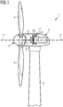
- FIG. 1 shows a wind turbine 1 according to the invention.
- the wind turbine 1 comprises a tower 2, which is mounted on a non-depicted foundation.
- a nacelle 3 is arranged on top of the tower 2.
- the wind turbine 1 further comprises a wind rotor 5 having at least one blade 4 (in the embodiment of Figure 1 , the wind rotor comprises three blades 4, of which only two blades 4 are visible).
- the wind rotor 5 is rotatable around a rotational axis Y.
- the blades 4 extend substantially radially with respect to the rotational axis Y.
- the wind turbine 1 comprises an electric generator 11, including a stator 20 and a rotor 30.
- the rotor 30 is rotatable with respect to the stator 20 about the rotational axis Y.
- the wind rotor 5 is rotationally coupled with the electric generator 11 either directly, e.g. direct drive or by means of a rotatable main shaft 9 and/or through a gear box (not shown in Figure 1 ).
- a schematically depicted bearing assembly 8 is provided in order to hold in place the main shaft 9 and the rotor 5.
- the rotatable main shaft 9 extends along the rotational axis Y.
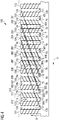
- the stator 20 has a plurality of teeth 101, 102, 103, 104 , 105, 106, 107, 108, 109, 110, 111, 112 alternating with a plurality of slots 1, 2, 3, 4, 5, 6, 7, 8, 9, 10, 11, 12 in a circumferential direction X of the stator 20, circumferentially orientated with respect to the rotational axis Y.
- Each of the plurality of slots 1, 2, 3, 4, 5, 6, 7, 8, 9, 10, 11, 12 extends along a radial direction R, i.e. orthogonally to the the rotational axis Y, from a respective slot bottom 1b, 2b, 3b, 4b, 5b, 6b, 7b, 8b, 9b, 10b, 11b, 12b to a respective slot top 1a, 2a, 3a, 4a, 5a, 6a, 7a, 8a, 9a, 10a, 11a, 12a.
- the electric generator 11 includes a concentrated winding layout 100 comprising a plurality of coils 201, 202, 203, 204, 205, 206, 207, 208, 209, 210, 211, 212 wound on the plurality teeth 101, 102, 103, 104, 105, 106, 107, 108, 109, 110, 111, 112 and belonging to at least six phases A1, A2, B1, B2, C1, C2, each slot 1, 2, 3, 4, 5, 6, 7, 8, 9, 10, 11, 12 housing at least two coils, each phase A1, A2, B1, B2, C1, C2 comprising a first coil 201, 202, 203, 204, 205, 206 and a second coil 207, 208, 209, 210, 211, 212, the second coil 207, 208, 209, 210, 211, 212 of one phase being wound in opposite direction with respect to the respective first coil 201, 202, 203, 204, 205, 206 of the same
- the concentrated winding layout 100 further comprises a plurality of interconnections 301, 302, 303, 304, 305, 306 connecting the first and second coil of each phase, the interconnections 301, 302, 303, 304, 305, 306 being parallel to each other.
- the coils 201, 202, 203, 204, 205, 206, 207, 208, 209, 210, 211, 212 and the interconnections 301, 302, 303, 304, 305, 306 carry respective insulations on the respective surfaces.
- FIG. 2 schematically shows for each phase A1, A2, B1, B2, C1, C2 the respective first coil 201, 202, 203, 204, 205, 206 and second coil 207, 208, 209, 210, 211, 212 as detailed in the following.
- Each interconnection 301, 302, 303, 304, 305, 306 is schematically represented by a point.
- Figure 3 schematically shows the correspondent voltage vector diagram.
- the first set of coils 201, 203, 205, 207, 209, 211 are electrically separated from the second set of coils 202, 204, 206, 208, 210, 212 by a phase angle ⁇ of 30°.
- the phase angle ⁇ may have any other value, for example 60°.
- the concentrated winding layout 100 comprises a first set of coils 201, 203, 205, 207, 209, 211 and a second set of coils 202, 204, 206, 208, 210, 212, respectively corresponding to a first set of three phases A1, B1, C1 and to a second set of three phases A2, B2, C2.
- Each first set of coils 201, 203, 205, 207, 209, 211 and of the second set of coils 202, 204, 206, 208, 210, 212 correspond to a respective three-phase system.
- the first set of coils 201, 203, 205, 207, 209, 211 is connected through three respective interconnections 301, 302, 303.
- the second set of coils 202, 204, 206, 208, 210, 212 is connected through three other respective interconnections 304, 305, 306.
- the concentrated winding layout may include a different number of phases, for example more than two three-phase systems.
- the first set of coils 201, 203, 205, 207, 209, 211 is electrically connected in series to the second set of coils 202, 204, 206, 208, 210, 212.
- the first set of coils 201, 203, 205, 207, 209, 211 are wound on a respective first set of teeth 101, 103, 105, 107, 109, 111 and the second set of coils 202, 204, 206, 208, 210, 212 are wound on a respective second set of teeth 102, 104, 106, 108, 110, 112 alternating with the first set of teeth 101, 103, 105, 107, 109, 111 in the circumferential direction X.
- the first set of coils 201, 203, 205, 207, 209, 211 comprises, along the circumferential direction X:
- the first coils 201, 203, 205 are wound according to a first direction, while the second coils 207, 209, 211 are wound according to a second direction, opposite to the first direction.
- the first coils 201, 203, 205 are wound clockwise, while the second coils 207, 209, 211 are wound anticlockwise.
- the first coils 201, 203, 205 are wound anticlockwise, while the second coils 207, 209, 211 are wound clockwise.
- the slots 1 - 12 can be identified as a series of slots oriented according to the circumferential direction X from a first slot 1 to a twelfth slot 12.
- the first set of coil 201, 203, 205, 207, 209, 211 is connected in the slots 1, 2, 3, 4, 5, 6, 7, 8, 9, 10, 11, 12 in such a way that:
- the second set of coils 202, 204, 206, 208, 210, 212 comprises, along the circumferential direction X:
- the first coils 202, 204, 206 are wound according to the second direction, while the second coils 208, 210, 212 are wound according to the first direction.
- the second set of coil 202, 204, 206, 208, 210, 212 is connected in the slots 1, 2, 3, 4, 5, 6, 7, 8, 9, 10, 11, 12 in such a way that:
- each of the interconnections 301, 302, 303, 304, 305, 306 extends between the slot top 12a, 2a, 4a, 6a of one slot 12, 2, 4, 6 to the slot bottom 6b, 8b, 10b, 12b of another slot 6, 8, 10, 12.. This assures that the interconnections 301, 302, 303, 304, 305, 306 are parallel to each other and have the same length.
- Each of the interconnections 301, 302, 303, 304, 305, 306 extends through six respective teeth and five respective slots, i.e. each of the interconnections 301, 302, 303, 304, 305, 306 connects two slots which are separated to each other by six respective teeth and five respective slots.
- the plurality of slots 1, 2, 3, 4, 5, 6, 7, 8, 9, 10, 11, 12 can be considered divided into comprises a first set of slots 2, 4, 6, 8, 10, 12 and a second set of slots 1, 3, 5, 7, 9, 11 alternating with the first set of slots 2, 4, 6, 8, 10, 12 in the circumferential direction X, each of the interconnections 301, 302, 303, 304, 305, 306 extending between two respective slots of the first set of slots 2, 4, 6, 8, 10, 12.
- the second set of slots 1, 3, 5, 7, 9, 11 houses the inputs 401, 402, 403, 404, 405, 406 of the phases A1, A2, B1, B2, C1, C2 and the neutral outputs N.
- the above described winding layout 100 can be repeated N times (N being an integer or a fraction) upstream the first tooth 101 of the first set of teeth 101, 103, 105, 107, 109, 111 or downstream the twelfth slot 12 "Upstream" and "downstream” are referred to the circumferential direction X.
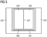
- a slot 501 (corresponding to any of the slots 1, 2, 3, 4, 5, 6, 7, 8, 9, 10, 11, 12 of Figure 4 ) between two teeth 502 and 503 is shown.
- the slot 501 houses two adjacent phases 504, 505.
- a wall insulator 506 is provided between each of the phases 504, 505 and the walls of the teeth 502 and 503.
- a phase separator 507 oriented radially separates the phases 504, 505 from one another. According to the present invention the thickness of the phase separator 507 can be minimized, as a consequence of the reduction of the voltage difference between the phases 504, 505.
- the phase separator 507 is not present the voltage difference between the phases 504, 505 being reduced to a minimum or null value. In such cases the insulation on the surface of the coils of each phase 504, 505 is enough to provide an effective insulation between the phases 504, 505.
Landscapes
- Engineering & Computer Science (AREA)
- Power Engineering (AREA)
- Windings For Motors And Generators (AREA)
Priority Applications (5)
| Application Number | Priority Date | Filing Date | Title |
|---|---|---|---|
| EP18190014.3A EP3614533A1 (de) | 2018-08-21 | 2018-08-21 | Konzentrierte wicklungsanordnung für einen stator einer elektrischen wechselstrommaschine |
| PCT/EP2019/072139 WO2020038886A1 (en) | 2018-08-21 | 2019-08-19 | Concentrated winding layout for a stator of an electrical ac machine |
| EP19761779.8A EP3807979A1 (de) | 2018-08-21 | 2019-08-19 | Konzentriertes wicklungslayout für einen stator einer elektrischen wechselstrommaschine |
| US17/269,444 US20210242740A1 (en) | 2018-08-21 | 2019-08-19 | Concentrated winding layout for a stator of an electrical ac machine |
| CN201980054312.1A CN112534684A (zh) | 2018-08-21 | 2019-08-19 | 用于ac电机定子的集中绕组布局 |
Applications Claiming Priority (1)
| Application Number | Priority Date | Filing Date | Title |
|---|---|---|---|
| EP18190014.3A EP3614533A1 (de) | 2018-08-21 | 2018-08-21 | Konzentrierte wicklungsanordnung für einen stator einer elektrischen wechselstrommaschine |
Publications (1)
| Publication Number | Publication Date |
|---|---|
| EP3614533A1 true EP3614533A1 (de) | 2020-02-26 |
Family
ID=63350438
Family Applications (2)
| Application Number | Title | Priority Date | Filing Date |
|---|---|---|---|
| EP18190014.3A Withdrawn EP3614533A1 (de) | 2018-08-21 | 2018-08-21 | Konzentrierte wicklungsanordnung für einen stator einer elektrischen wechselstrommaschine |
| EP19761779.8A Withdrawn EP3807979A1 (de) | 2018-08-21 | 2019-08-19 | Konzentriertes wicklungslayout für einen stator einer elektrischen wechselstrommaschine |
Family Applications After (1)
| Application Number | Title | Priority Date | Filing Date |
|---|---|---|---|
| EP19761779.8A Withdrawn EP3807979A1 (de) | 2018-08-21 | 2019-08-19 | Konzentriertes wicklungslayout für einen stator einer elektrischen wechselstrommaschine |
Country Status (4)
| Country | Link |
|---|---|
| US (1) | US20210242740A1 (de) |
| EP (2) | EP3614533A1 (de) |
| CN (1) | CN112534684A (de) |
| WO (1) | WO2020038886A1 (de) |
Cited By (1)
| Publication number | Priority date | Publication date | Assignee | Title |
|---|---|---|---|---|
| US20210242740A1 (en) * | 2018-08-21 | 2021-08-05 | Siemens Gamesa Renewable Energy A/S | Concentrated winding layout for a stator of an electrical ac machine |
Citations (4)
| Publication number | Priority date | Publication date | Assignee | Title |
|---|---|---|---|---|
| EP1764900A2 (de) * | 2005-09-14 | 2007-03-21 | Astronics Advanced Electronic Systems Corp. | Redundante Wicklungen mit Strombegrenzungsvorrichtungen für elektrische Maschinen |
| US20100289372A1 (en) * | 2009-05-14 | 2010-11-18 | Denso Corporation | Electric rotating machine having improved stator coil arrangement for reducing magnetic noise and torque ripple |
| EP2372878A2 (de) * | 2010-03-31 | 2011-10-05 | Kokusan Denki Co., Ltd. | Elektrische Drehmaschine und Verfahren zur Herstellung eines Stators dafür |
| WO2013080720A1 (ja) * | 2011-12-02 | 2013-06-06 | 株式会社 日立製作所 | アキシャルギャップ型回転電機及びその製造方法 |
Family Cites Families (9)
| Publication number | Priority date | Publication date | Assignee | Title |
|---|---|---|---|---|
| JP5510703B2 (ja) * | 2009-08-21 | 2014-06-04 | 株式会社デンソー | 回転電機及びその制御システム |
| DE102011084716A1 (de) * | 2011-10-18 | 2013-04-18 | Robert Bosch Gmbh | Elektrische Maschine |
| DK3557733T3 (da) * | 2018-04-18 | 2021-05-31 | Siemens Gamesa Renewable Energy As | Spoledannelse i en elektrisk maskine med koncentrerede viklinger |
| EP3614533A1 (de) * | 2018-08-21 | 2020-02-26 | Siemens Gamesa Renewable Energy A/S | Konzentrierte wicklungsanordnung für einen stator einer elektrischen wechselstrommaschine |
| EP3648305B1 (de) * | 2018-10-30 | 2021-06-30 | Siemens Gamesa Renewable Energy A/S | Elektrische maschine mit hybridverzahnung |
| EP3823138A1 (de) * | 2019-11-18 | 2021-05-19 | Siemens Gamesa Renewable Energy A/S | Konzentriertes wicklungslayout für einen stator einer elektrischen wechselstrommaschine |
| DE102020126704A1 (de) * | 2020-10-12 | 2022-04-14 | Valeo Siemens Eautomotive Germany Gmbh | Stator für eine elektrische Maschine mit verbessertem Schutz gegen Potentialdifferenzen zwischen benachbarten Statorspulen |
| US12431752B2 (en) * | 2021-09-17 | 2025-09-30 | Rolls-Royce Electrical Norway AS | Continuous wave-winding for stator |
| CN115441605A (zh) * | 2022-08-08 | 2022-12-06 | 杭州硅湾智能装备有限公司 | 一种六相开关磁阻电机及无位置传感器转子位置估算方法和系统 |
-
2018
- 2018-08-21 EP EP18190014.3A patent/EP3614533A1/de not_active Withdrawn
-
2019
- 2019-08-19 EP EP19761779.8A patent/EP3807979A1/de not_active Withdrawn
- 2019-08-19 US US17/269,444 patent/US20210242740A1/en not_active Abandoned
- 2019-08-19 CN CN201980054312.1A patent/CN112534684A/zh active Pending
- 2019-08-19 WO PCT/EP2019/072139 patent/WO2020038886A1/en not_active Ceased
Patent Citations (4)
| Publication number | Priority date | Publication date | Assignee | Title |
|---|---|---|---|---|
| EP1764900A2 (de) * | 2005-09-14 | 2007-03-21 | Astronics Advanced Electronic Systems Corp. | Redundante Wicklungen mit Strombegrenzungsvorrichtungen für elektrische Maschinen |
| US20100289372A1 (en) * | 2009-05-14 | 2010-11-18 | Denso Corporation | Electric rotating machine having improved stator coil arrangement for reducing magnetic noise and torque ripple |
| EP2372878A2 (de) * | 2010-03-31 | 2011-10-05 | Kokusan Denki Co., Ltd. | Elektrische Drehmaschine und Verfahren zur Herstellung eines Stators dafür |
| WO2013080720A1 (ja) * | 2011-12-02 | 2013-06-06 | 株式会社 日立製作所 | アキシャルギャップ型回転電機及びその製造方法 |
Cited By (1)
| Publication number | Priority date | Publication date | Assignee | Title |
|---|---|---|---|---|
| US20210242740A1 (en) * | 2018-08-21 | 2021-08-05 | Siemens Gamesa Renewable Energy A/S | Concentrated winding layout for a stator of an electrical ac machine |
Also Published As
| Publication number | Publication date |
|---|---|
| CN112534684A (zh) | 2021-03-19 |
| US20210242740A1 (en) | 2021-08-05 |
| EP3807979A1 (de) | 2021-04-21 |
| WO2020038886A1 (en) | 2020-02-27 |
Similar Documents
| Publication | Publication Date | Title |
|---|---|---|
| US8471428B2 (en) | Rotating electrical machine | |
| EP2728713A1 (de) | Elektrische Maschine | |
| US9847684B2 (en) | Stator and rotating electric machine | |
| EP3560075B1 (de) | Elektrische maschine mit segmentiertem stator | |
| EP2871755B1 (de) | Drehmaschine | |
| EP2728712A1 (de) | Leistungsgenerator für eine Wasserturbine | |
| CN111919363A (zh) | 交流电机与变流器单元的组合和风力发电设备 | |
| EP4029125B1 (de) | Wickelschema einer konzentrierten wicklung für einen stator einer elektrischen wechselstrommaschine | |
| US12431752B2 (en) | Continuous wave-winding for stator | |
| US20210242740A1 (en) | Concentrated winding layout for a stator of an electrical ac machine | |
| EP3514922B2 (de) | Elektrische maschine mit mehreren bruchlochwicklungen | |
| JP5172439B2 (ja) | 回転電機の固定子および回転電機 | |
| US20110266912A1 (en) | Rotating electric machine with a stator winding comprising a plurality of coils and method for manufacturing same | |
| EP2800248B1 (de) | Statorwicklung eines elektrischen Generators | |
| EP3550699B1 (de) | Wicklungsentwurfsanordnung für eine elektrische maschine und windenergieanlage | |
| EP4701045A1 (de) | Statorsegment, elektrische maschine und windkraftanlage | |
| EP4478587A1 (de) | Stator einer elektrischen maschine | |
| EP3496233A1 (de) | Elektrischer generator mit endwindungen mit reduziertem axialem überstand | |
| JP2005204420A (ja) | 回転電機の固定子 | |
| KR20240157754A (ko) | 다중-권선 세트 분수 슬롯 동기 기계 | |
| CN115776187A (zh) | 定子、电机及制造定子的方法 |
Legal Events
| Date | Code | Title | Description |
|---|---|---|---|
| PUAI | Public reference made under article 153(3) epc to a published international application that has entered the european phase |
Free format text: ORIGINAL CODE: 0009012 |
|
| AK | Designated contracting states |
Kind code of ref document: A1 Designated state(s): AL AT BE BG CH CY CZ DE DK EE ES FI FR GB GR HR HU IE IS IT LI LT LU LV MC MK MT NL NO PL PT RO RS SE SI SK SM TR |
|
| AX | Request for extension of the european patent |
Extension state: BA ME |
|
| STAA | Information on the status of an ep patent application or granted ep patent |
Free format text: STATUS: THE APPLICATION IS DEEMED TO BE WITHDRAWN |
|
| 18D | Application deemed to be withdrawn |
Effective date: 20200827 |