EP3614605A1 - Kommunikationsverfahren, endgerät und netzwerkvorrichtung - Google Patents
Kommunikationsverfahren, endgerät und netzwerkvorrichtung Download PDFInfo
- Publication number
- EP3614605A1 EP3614605A1 EP18794038.2A EP18794038A EP3614605A1 EP 3614605 A1 EP3614605 A1 EP 3614605A1 EP 18794038 A EP18794038 A EP 18794038A EP 3614605 A1 EP3614605 A1 EP 3614605A1
- Authority
- EP
- European Patent Office
- Prior art keywords
- terminal
- data segment
- orthogonal cover
- cover code
- network device
- Prior art date
- Legal status (The legal status is an assumption and is not a legal conclusion. Google has not performed a legal analysis and makes no representation as to the accuracy of the status listed.)
- Granted
Links
Images




Classifications
-
- H—ELECTRICITY
- H04—ELECTRIC COMMUNICATION TECHNIQUE
- H04L—TRANSMISSION OF DIGITAL INFORMATION, e.g. TELEGRAPHIC COMMUNICATION
- H04L27/00—Modulated-carrier systems
- H04L27/26—Systems using multi-frequency codes
- H04L27/2601—Multicarrier modulation systems
- H04L27/2602—Signal structure
-
- H—ELECTRICITY
- H04—ELECTRIC COMMUNICATION TECHNIQUE
- H04L—TRANSMISSION OF DIGITAL INFORMATION, e.g. TELEGRAPHIC COMMUNICATION
- H04L5/00—Arrangements affording multiple use of the transmission path
- H04L5/0001—Arrangements for dividing the transmission path
- H04L5/0014—Three-dimensional division
- H04L5/0023—Time-frequency-space
-
- H—ELECTRICITY
- H04—ELECTRIC COMMUNICATION TECHNIQUE
- H04L—TRANSMISSION OF DIGITAL INFORMATION, e.g. TELEGRAPHIC COMMUNICATION
- H04L27/00—Modulated-carrier systems
- H04L27/26—Systems using multi-frequency codes
- H04L27/2601—Multicarrier modulation systems
- H04L27/2602—Signal structure
- H04L27/26035—Maintenance of orthogonality, e.g. for signals exchanged between cells or users, or by using covering codes or sequences
-
- H—ELECTRICITY
- H04—ELECTRIC COMMUNICATION TECHNIQUE
- H04L—TRANSMISSION OF DIGITAL INFORMATION, e.g. TELEGRAPHIC COMMUNICATION
- H04L27/00—Modulated-carrier systems
- H04L27/26—Systems using multi-frequency codes
- H04L27/2601—Multicarrier modulation systems
- H04L27/2602—Signal structure
- H04L27/2604—Multiresolution systems
-
- H—ELECTRICITY
- H04—ELECTRIC COMMUNICATION TECHNIQUE
- H04L—TRANSMISSION OF DIGITAL INFORMATION, e.g. TELEGRAPHIC COMMUNICATION
- H04L27/00—Modulated-carrier systems
- H04L27/26—Systems using multi-frequency codes
- H04L27/2601—Multicarrier modulation systems
- H04L27/2626—Arrangements specific to the transmitter only
- H04L27/2627—Modulators
- H04L27/2634—Inverse fast Fourier transform [IFFT] or inverse discrete Fourier transform [IDFT] modulators in combination with other circuits for modulation
- H04L27/2636—Inverse fast Fourier transform [IFFT] or inverse discrete Fourier transform [IDFT] modulators in combination with other circuits for modulation with FFT or DFT modulators, e.g. standard single-carrier frequency-division multiple access [SC-FDMA] transmitter or DFT spread orthogonal frequency division multiplexing [DFT-SOFDM]
-
- H—ELECTRICITY
- H04—ELECTRIC COMMUNICATION TECHNIQUE
- H04L—TRANSMISSION OF DIGITAL INFORMATION, e.g. TELEGRAPHIC COMMUNICATION
- H04L5/00—Arrangements affording multiple use of the transmission path
- H04L5/0001—Arrangements for dividing the transmission path
- H04L5/0014—Three-dimensional division
- H04L5/0016—Time-frequency-code
- H04L5/0019—Time-frequency-code in which one code is applied, as a temporal sequence, to all frequencies
-
- H—ELECTRICITY
- H04—ELECTRIC COMMUNICATION TECHNIQUE
- H04L—TRANSMISSION OF DIGITAL INFORMATION, e.g. TELEGRAPHIC COMMUNICATION
- H04L5/00—Arrangements affording multiple use of the transmission path
- H04L5/003—Arrangements for allocating sub-channels of the transmission path
- H04L5/0053—Allocation of signalling, i.e. of overhead other than pilot signals
-
- H—ELECTRICITY
- H04—ELECTRIC COMMUNICATION TECHNIQUE
- H04W—WIRELESS COMMUNICATION NETWORKS
- H04W72/00—Local resource management
- H04W72/20—Control channels or signalling for resource management
- H04W72/21—Control channels or signalling for resource management in the uplink direction of a wireless link, i.e. towards the network
-
- H—ELECTRICITY
- H04—ELECTRIC COMMUNICATION TECHNIQUE
- H04L—TRANSMISSION OF DIGITAL INFORMATION, e.g. TELEGRAPHIC COMMUNICATION
- H04L5/00—Arrangements affording multiple use of the transmission path
- H04L5/0001—Arrangements for dividing the transmission path
- H04L5/0003—Two-dimensional division
- H04L5/0005—Time-frequency
- H04L5/0007—Time-frequency the frequencies being orthogonal, e.g. OFDM(A) or DMT
-
- H—ELECTRICITY
- H04—ELECTRIC COMMUNICATION TECHNIQUE
- H04L—TRANSMISSION OF DIGITAL INFORMATION, e.g. TELEGRAPHIC COMMUNICATION
- H04L5/00—Arrangements affording multiple use of the transmission path
- H04L5/003—Arrangements for allocating sub-channels of the transmission path
- H04L5/0037—Inter-user or inter-terminal allocation
Definitions
- This application relates to the communications field, and more specifically, to a communication method, a terminal, and a network device.
- uplink control information (uplink control indicator, UCI) of different lengths can be transmitted using physical uplink control channels (physical uplink control channel, PUCCH) of different formats.
- uplink control information with a length of 1 or 2 bits can be transmitted still using long term evolution (long term evolution, LTE) PUCCH format 1a/1b, and that uplink control information with a length greater than X bits can be transmitted still using LTE PUCCH format 4, where a value of X is to be determined.
- LTE long term evolution
- This application provides a communication method, a terminal and a network device, to transmit uplink control information, so that frequency gains of the uplink control information can be increased, transmission flexibility of the uplink control information can be improved, and resource utilization can be increased.
- a communication method includes: repeating, by a first terminal, to-be-transmitted uplink control information for N times to obtain a first data segment, where N is a positive integer; determining, by the first terminal, an orthogonal cover code based on N; multiplying, by the first terminal, the first data segment by the orthogonal cover code to obtain a second data segment; and sending, by the first terminal, the second data segment.
- the first terminal repeats the to-be-transmitted uplink control information for N times, so that frequency diversity gains of the to-be-transmitted uplink control information can be increased.
- the first terminal multiplies the to-be-transmitted uplink control information by the orthogonal cover code, so that the to-be-transmitted uplink control information can present a comb-like structure in frequency domain.
- the comb-like structure can be staggered from a frequency-domain comb-like structure obtained by multiplying uplink control information of another terminal by an orthogonal cover code, so that a plurality of terminals use a same time-frequency resource to transmit uplink control information, thereby increasing resource utilization.
- a quantity of repetitions of uplink control information of a terminal and an orthogonal cover code can be determined flexibly, so that the uplink control information can be transmitted more flexibly.
- the determining, by the first terminal, an orthogonal cover code based on N includes: determining, by the first terminal, the orthogonal cover code based on the quantity N of repetitions and a correspondence between the quantity N of repetitions and the orthogonal cover code.
- the communication method further includes: receiving, by the first terminal, indication information sent by a network device, where the indication information is used to indicate N; and determining, by the first terminal, N based on the indication information.
- the quantity of repetitions of the uplink control information of the terminal is determined by the network device. Because the network device can learn communication information of a plurality of terminals, the network device can determine a proper quantity of repetitions for each terminal, thereby increasing the resource utilization.
- the communication method further includes: determining, by the first terminal, N based on uplink signal quality.
- the communication method further includes: determining, by the first terminal, N based on a quantity M of symbols represented by constellation points of the to-be-transmitted uplink control information, where M is a positive integer.
- the determining, by the first terminal, N based on a quantity M of symbols represented by constellation points of the to-be-transmitted uplink control information includes: determining, by the first terminal, a ratio of a quantity of subcarriers included in a first resource to M as N.
- the communication method further includes: sending, by the first terminal, indication information to a network device, where the indication information is used to indicate N.
- the terminal When the quantity of repetitions is determined by the terminal, the terminal sends the quantity of repetitions to the network device, so that the network device can receive the uplink control information of the terminal based on the quantity of repetitions, thereby increasing efficiency of the network device.
- the sending, by the first terminal, the second data segment includes: sending, by the first terminal on a first resource, the second data segment, where a third data segment is also sent on the first resource, and the third data segment is obtained by repeating uplink control information of a second terminal for K times, where K is not equal to N, and K is a positive integer.
- a communication method includes: receiving, by a network device, a second data segment sent by a first terminal, where the second data segment is obtained by the first terminal by processing a first data segment based on an orthogonal cover code, and the first data segment is obtained by repeating uplink control information of the first terminal for N times, where N is a positive integer; determining, by the network device, a conjugated orthogonal cover code based on N; multiplying, by the network terminal, the conjugated cover code by the second data segment to obtain the first data segment; and performing, by the network device, N rounds of deduplication processing on the first data segment to obtain the uplink control information of the first terminal.
- the first terminal repeats the to-be-transmitted uplink control information for N times, so that frequency diversity gains of the to-be-transmitted uplink control information can be increased.
- the first terminal multiplies the to-be-transmitted uplink control information by the orthogonal cover code, so that the to-be-transmitted uplink control information can present a comb-like structure in frequency domain.
- the comb-like structure can be staggered from a frequency-domain comb-like structure obtained by multiplying uplink control information of another terminal by an orthogonal cover code, so that a plurality of terminals use a same time-frequency resource to transmit uplink control information.
- the determining, by the network device, a conjugated orthogonal cover code based on N includes: determining, by the network device, the conjugated orthogonal cover code based on N and a correspondence between the quantity N of repetitions and the conjugated orthogonal cover code.
- the communication method further includes: receiving, by the network device, indication information sent by the first terminal, where the indication information is used to indicate N.
- the communication method further includes: determining, by the network device, N based on at least one of uplink channel state information of the first terminal and an uplink channel signal-to-noise ratio of the first terminal; and sending, by the network device, indication information to the first terminal, where the indication information is used to indicate N.
- the quantity of repetitions of the uplink control information of the terminal is determined by the network device. Because the network device can learn communication information of a plurality of terminals, the network device can determine a proper quantity of repetitions for each terminal, thereby increasing resource utilization.
- the receiving, by a network device, a second data segment sent by a first terminal includes: receiving, by the network device on a first resource, the second data segment sent by the first terminal; and the communication method further includes: receiving, by the network device on the first resource, a third data segment sent by a second terminal; and performing, by the network device, conjugated orthogonal cover code processing and K rounds of deduplication processing on the third data segment to obtain uplink control information of the second terminal, where K is not equal to N, and K is a positive integer.
- this application provides a terminal.
- the terminal includes a module configured to perform the communication method according to any one of the first aspect or the possible implementations of the first aspect.
- this application provides a network device.
- the network device includes a module configured to perform the communication method according to any one of the first aspect or the possible implementations of the first aspect.
- this application provides a terminal.
- the terminal includes a processor and a transmitter.
- the processor is configured to execute code.
- the processor and the transmitter implement the communication method according to any one of the first aspect or the possible implementations of the first aspect.
- the terminal may further include a memory, configured to store the code executed by the processor.
- the terminal may further include a receiver, configured to receive information sent by another device.
- this application provides a network device.
- the network device includes a processor and a receiver.
- the processor is configured to execute code.
- the processor and the receiver implement the communication method according to any one of the first aspect or the possible implementations of the first aspect.
- the network device may further include a memory, configured to store the code executed by the processor.
- the network device may further include a transmitter, configured to send information to another device.
- this application provides a computer-readable storage medium.
- the computer-readable storage medium stores program code executed by a terminal, and the program code includes an instruction used to perform the communication method according to any one of the first aspect or the possible implementations of the first aspect.
- this application provides a computer-readable storage medium.
- the computer-readable storage medium stores program code executed by a network device, and the program code includes an instruction used to perform the communication method according to any one of the first aspect or the possible implementations of the first aspect.
- this application provides a computer program product including an instruction.
- the terminal When the computer program product runs on a terminal, the terminal performs the communication method according to any one of the first aspect or the possible implementations of the first aspect.
- this application provides a computer program product including an instruction.
- the computer program product runs on a network device, the network device performs the communication method according to any one of the first aspect or the possible implementations of the first aspect.
- FIG. 1 is an example structural diagram of a communications system to which a communication method in an embodiment of this application is applicable. It should be understood that a system architecture is not limited to that shown in FIG. 1 in the embodiments of this application.
- an apparatus in FIG. 1 may be hardware, may be software obtained through function division, or may be a combination thereof.
- a specific example of the communications system shown in FIG. 1 may be an LTE system or an NR system, where the NR system may also be referred to as a 5G system.
- a network device 110 in FIG. 1 may be a base station. It should be understood that a specific type of the base station is not limited in the embodiments of this application. In systems using different radio access technologies, a device having a function of a base station may have different names. For ease of description, in all the embodiments of this application, the apparatuses providing a wireless communication function for terminals are collectively referred to as base stations, such as a base station device and a small cell device (Pico) in a future network.
- base stations such as a base station device and a small cell device (Pico) in a future network.
- a terminal 120 in FIG. 1 may be user equipment (User Equipment, UE).
- the UE may communicate with one or more core networks (Core Network) through a radio access network (Radio Access Network, RAN).
- the terminal may also be referred to as an access terminal, a terminal device, a subscriber unit, a subscriber station, a mobile station, a mobile console, a remote station, a remote terminal, a mobile device, a user terminal, a wireless network device, a user agent, or a user apparatus.
- the terminal may be a cellular phone, a cordless phone, a session initiation protocol (Session Initiation Protocol, SIP) phone, a wireless local loop (Wireless Local Loop, WLL) station, a personal digital assistant (Personal Digital Assistant, PDA), a handheld device with a wireless communication function, a computing device, another device connected to a wireless modem, a vehicle-mounted device, a wearable device, a terminal device in an internet of things or an internet of vehicles, a terminal device of any form in a future network, or the like.
- SIP Session Initiation Protocol
- WLL Wireless Local Loop
- PDA Personal Digital Assistant
- the network device 110 and the terminal 120 communicate with each other.
- the terminal 120 may send UCI to the network device 110 over a PUCCH, and correspondingly, the network device 110 receives the UCI sent by the terminal 120, to implement other uplink-downlink transmission between the terminal 120 and the network device 110.
- the UCI sent by the terminal 120 to the network device may include hybrid automatic repeat request (hybrid automatic repeat request, HARQ) acknowledgement (acknowledgement, ACK) information, channel state information (channel state information, CSI), scheduling request information, and/or the like.
- hybrid automatic repeat request hybrid automatic repeat request
- HARQ hybrid automatic repeat request
- acknowledgement acknowledgement
- ACK channel state information
- CSI scheduling request information
- a correspondence between a quantity of repetitions and an orthogonal cover code may be configured in the terminal 120.
- Each quantity of repetitions may correspond to a plurality of orthogonal cover codes.
- a correspondence between a quantity of repetitions and a conjugation of an orthogonal cover code may also be configured in the terminal 120.
- a conjugation of an orthogonal cover code may be referred to as a conjugated orthogonal cover code.
- a quantity of repetitions M may correspond to M orthogonal cover codes
- the M orthogonal cover codes may be: [1,1,1,...1], 1 , e j 2 N ⁇ , e j 4 N ⁇ , ... e j 2 M ⁇ 1 M ⁇ , 1 , e j 4 N ⁇ , e j 8 N ⁇ , ... e j 4 M ⁇ 1 M ⁇ , ..., and 1 , e j 2 M ⁇ 1 M ⁇ , e j 4 M ⁇ 1 M ⁇ , ... e j 2 M ⁇ 1 2 M ⁇ .
- orthogonal cover codes corresponding to a quantity 4 of repetitions include: [1,1,1,1], [1,j,-1,j], [1,-1,1,-1], and [1,-j,-1,-j].
- Two orthogonal cover codes corresponding to a quantity of repetitions 2 include: [1,1], and [1,j].
- each quantity of repetitions may correspond to a plurality of orthogonal cover codes or a plurality of conjugated orthogonal cover codes.
- the correspondence may be the same as the correspondence between a quantity of repetitions and an orthogonal cover code that is configured in the terminal 120; and if the correspondence between a quantity of repetitions and a conjugated orthogonal cover code is configured in the network device 110, the conjugated orthogonal cover code may be a conjugation of the orthogonal cover code in the terminal.
- FIG. 2 is a schematic flowchart of a communication method performed by a terminal. It should be understood that FIG. 2 shows steps or operations of the communication method, but these steps or operations are only examples. In this embodiment of this application, other operations or variations of the operations in FIG. 2 may also be performed. In addition, the steps in FIG. 2 may be performed in a sequence different from that presented in FIG. 2 , and not all the operations in FIG. 2 are necessarily performed.
- S210 The terminal repeats to-be-transmitted uplink control information for N times to obtain a first data segment, where N is a positive integer.
- the repeating, by the terminal, to-be-transmitted uplink control information for N times may include: repeating, by the terminal for N times, a symbol that is represented by a constellation point and obtained by modulating the to-be-transmitted uplink control information. For example, if three symbols represented by constellation points are obtained by modulating the to-be-transmitted uplink control information, 12 symbols represented by the constellation points are obtained by repeating the three symbols represented by the constellation points for four times, where the 12 symbols represented by the constellation points are a first data segment.
- the symbol, represented by the constellation point, of the to-be-transmitted uplink control information may be a quadrature phase shift keying (quadrature phase shift keying, QPSK) symbol obtained by performing QPSK modulation on the to-be-transmitted uplink control information; or may be a binary phase shift keying (binary phase shift key, BPSK) symbol obtained by performing BPSK modulation on the to-be-transmitted uplink control information.
- QPSK quadrature phase shift keying
- BPSK binary phase shift key
- the terminal may determine a quantity of encoded bits of the uplink control information of the terminal 120 based on the quantity of subcarriers and a quantity of repetitions.
- the quantity of subcarriers used by the physical uplink control channel that carries the uplink control information of the terminal 120 is 12
- the quantity of repetitions of the uplink control information is 2
- a modulation scheme used by the terminal 120 is QPSK
- it indicates that a quantity of QPSK symbols available before the uplink control information of the terminal 120 is repeated is 6.
- every two encoded bits can be modulated into one QPSK symbol, it indicates that the quantity of the encoded bits of the uplink control information is 12.
- S220 The terminal determines an orthogonal cover code based on the quantity N of repetitions.
- the terminal may determine the orthogonal cover code corresponding to N, based on N and a correspondence between the quantity of repetitions and the orthogonal cover code that is configured in the terminal.
- the terminal 120 may further determine, based on an orthogonal cover code index sent by the network device 110, an orthogonal cover code corresponding to the index from the plurality of orthogonal cover codes corresponding to the quantity N of repetitions.
- S210 and S220 are not limited in this embodiment of this application.
- S220 may be performed before S210.
- S230 The terminal multiplies the first data segment by the orthogonal cover code to obtain a second data segment.
- the terminal multiplies the first data segment obtained in S210 by the orthogonal cover code obtained in S220, to obtain the second data segment.
- Terminals multiply the data segments obtained through repetition by orthogonal cover codes, so that frequency domain data of the uplink control information is arranged in a staggered manner on a carrier, allowing the plurality of terminals to use a same resource to transmit their respective uplink control information.
- three QSPK symbols obtained by repeating three QSPK symbols of the to-be-transmitted uplink control information for the first time may be multiplied by 1 in the orthogonal cover code [1,j,-1,-j]; three QSPK symbols obtained by repeating the three QSPK symbols for the second time is multiplied by j in the orthogonal cover code [1,j,-1,-j]; three QSPK symbols obtained by repeating the three QSPK symbols for the third time is multiplied by -1 in the orthogonal cover code [1,j,-1,-j]; and three QSPK symbols obtained by repeating the three QSPK symbols for the fourth time is multiplied by -j in the orthogonal cover code [1,j,-1,-j].
- a result obtained by multiplying the 12 QSPK symbols by the orthogonal cover code [1,j,-1,-j] is the second data segment.
- Terminals multiply the data segments obtained through repetition by orthogonal cover codes, so that frequency domain data of the uplink control information is arranged in a staggered manner on a carrier, allowing the plurality of terminals to use a same resource to transmit their respective uplink control information.
- To-be-transmitted uplink control information of each terminal includes three QPSK symbols. Each terminal repeats the respective three QPSK symbols for four times to obtain 12 QPSK symbols.
- Orthogonal cover codes of the four terminals correspond to [1,1,1,1], [1,j,-1,-j], [1,-1,1,-1], and [1,-j,-1,-j].
- Each terminal multiplies its QPSK symbols by the corresponding orthogonal cover code, and performs DFT processing to obtain a frequency-domain comb-like structure shown in FIG. 3 . It may be seen from FIG. 3 that the frequency-domain comb-like structures of the four terminals are arranged in a staggered manner without any conflict.
- S240 The terminal sends the second data segment.
- the sending, by the terminal, the second data segment may specifically include: performing discrete fourier transform (discrete fourier transform, DFT) on the second data segment; mapping data obtained through the DFT to a resource corresponding to an uplink control channel, which may be specifically mapping the data obtained through the DFT to a subcarrier corresponding to the uplink control channel; performing inverse fast fourier transform on data obtained through mapping, to obtain time domain data; and sending the time domain data.
- DFT discrete fourier transform
- the quantity N of repetitions may be determined by the terminal, or may be obtained by the terminal from the network device.
- the terminal may determine the quantity N of repetitions based on uplink channel state information, or the terminal may determine the quantity N of repetitions based on a quantity M of symbols represented by constellation points of the to-be-transmitted uplink control information.
- a better signal quality indicated by the uplink channel state information indicates a greater quantity of repetitions.
- the quantity of repetitions is determined as 8; or when the uplink signal quality of the terminal is less than the threshold, the quantity of repetitions is determined as 2.
- the terminal determines the quantity of repetitions of the to-be-transmitted uplink control information based on the uplink state information, so that the terminal can properly use a resource to transmit the uplink control information.
- the terminal may perform channel sounding by using a downlink reference signal, and obtain the uplink channel state information based on uplink-downlink channel reciprocity.
- the terminal may alternatively determine the quantity of repetitions based on information of another terminal, and this is not limited in this application.
- the determining, by the terminal, the quantity N of repetitions based on a quantity M of symbols represented by constellation points of the to-be-transmitted uplink control information may specifically include: determining, by the terminal, a ratio of a quantity of subcarriers included in a first resource to M as N, where the first resource is a resource used by the uplink control channel that carries the to-be-transmitted uplink control information.
- a result 4 obtained by dividing 12 by 3 may be determined as the quantity of repetitions of the three symbols, represented by constellation points, of the to-be-transmitted uplink control information.
- the terminal may send indication information to the network device, where the indication information indicates the quantity N of repetitions, so that the network terminal can receive the uplink control information of the terminal based on the quantity N of repetitions.
- the obtaining, by the terminal, the quantity N of repetitions from the network device may specifically include: receiving, by the terminal, indication information sent by the network device, where the indication information indicates the quantity N of repetitions; and determining, by the terminal, the quantity N of repetitions based on the indication information.
- the quantity N of repetitions of uplink control information of the terminal may be different from a quantity of repetitions of uplink control information of another terminal.
- a quantity of repetitions of to-be-transmitted uplink control information of the first terminal may be 2, and quantities of repetitions of to-be-transmitted uplink control information of the second terminal and the third terminal may both be 4.
- an orthogonal cover code of the first terminal may be [1,1]
- an orthogonal cover code of the second terminal may be [1,j,-1,-j]
- an orthogonal cover code of the third terminal may be [1,-j,-1,j].
- the to-be-transmitted uplink control information of the first terminal includes six QPSK symbols
- the to-be-transmitted uplink control information of the second terminal and the third terminal each includes three QPSK symbols
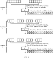
- a diagram of frequency-domain comb-like structures obtained by the three terminals by repeating their respective QPSK symbols of the to-be-transmitted uplink control information for the corresponding times and multiplying respective obtained QPSK symbols by the corresponding orthogonal cover codes is shown in FIG. 5 .
- FIG. 6 is a schematic flowchart of a communication method performed by a network device. It should be understood that FIG. 6 shows steps or operations of the communication method, but these steps or operations are only examples. In this embodiment of this application, other operations or variations of the operations in FIG. 6 may also be performed. In addition, the steps in FIG. 6 may be performed in a sequence different from that presented in FIG. 6 , and not all the operations in FIG. 6 are necessarily performed.
- the network device receives a second data segment sent by a terminal, where the second data segment is obtained by the first terminal by processing a first data segment based on an orthogonal cover code, and the first data segment is obtained by repeating uplink control information of the first terminal for N times, where N is a positive integer.
- the second data segment received by the network device may be the second data segment sent by the terminal in S240.
- the receiving, by the network device, a second data segment may specifically include: receiving time domain data sent by the terminal; performing fast fourier transformation (fast fourier transformation, FFT) on the time domain data, extracting data on a subcarrier corresponding to an uplink control resource, and performing channel equalization; and performing DFT on the equalized data to obtain the second data segment.
- FFT fast fourier transformation
- the network device 110 may further determine, from the plurality of orthogonal cover codes, an orthogonal cover code that should be used after the terminal 120 repeats the uplink control information for N times.
- the network device 110 may send indication information to the terminal 120, to indicate an index of an orthogonal cover code in the plurality of orthogonal cover codes corresponding to the quantity N of repetitions.
- orthogonal cover codes determined by the network device 110 for the different terminals should be different as much as possible. In this way, the uplink control information of the plurality of terminals is arranged on the same resource in a staggered manner without any collusion, thereby improving communication reliability.
- S620 The network device determines a conjugated orthogonal cover code based on N.
- the network device may determine an orthogonal cover code corresponding to N based on N and a correspondence between a quantity of repetitions and an orthogonal cover code that is configured in the network device; and then determine a conjugation of the orthogonal cover code as the conjugated orthogonal cover code.
- the network device may find the plurality of orthogonal cover codes corresponding to the quantity N of repetitions, based on N and a correspondence between a quantity of repetitions and an orthogonal cover code that is configured in the network device; determine one orthogonal cover code from the plurality of orthogonal cover codes based on an index of an orthogonal cover code used by the terminal; and determine a conjugation of the orthogonal cover code as a conjugated orthogonal cover code.
- the network device may determine the conjugated orthogonal cover code corresponding to N, based on N and a correspondence between a quantity of repetitions and a conjugated orthogonal cover code that is configured in the network device.
- the network device may find the plurality of conjugated orthogonal cover codes corresponding to the quantity N of repetitions based on a correspondence between a quantity of repetitions and a conjugated orthogonal cover code, and then determine one conjugated orthogonal cover code from the plurality of conjugated orthogonal cover codes based on an index of an orthogonal cover code used by the terminal 120.
- S630 The network device multiplies the conjugated orthogonal cover code by the second data segment to obtain the first data segment.
- the network device multiplies the second data segment obtained in S610 by the conjugated orthogonal cover code obtained in S620 to obtain the first data segment.
- the network device may obtain a first data segment including 12 symbols represented by constellation points.
- S640 The network device performs N rounds of deduplication processing on the first data segment to obtain the uplink control information of the first terminal.
- N 4
- four rounds of deduplication processing are performed on the first data segment including 12 symbols represented by constellation points, to obtain three symbols represented by constellation points.
- the three symbols represented by constellation points are symbols, represented by constellation points, of the uplink control information.
- the network device may demodulate the deduplicated symbols represented by constellation points, and decode data obtained through demodulation, to obtain the uplink control information.
- the quantity N of repetitions may be determined by the network device, or may be obtained from the terminal.
- the network device may determine the quantity of repetitions based on uplink channel state information and/or an uplink channel signal-to-noise ratio of the terminal.
- the quantity of repetitions is determined as 8; or when the signal-to-noise ratio of the terminal is less than the threshold, the quantity of repetitions is determined as 2.
- the network device determines the quantity of repetitions of the uplink control information of the terminal based on the information about the terminal, so that the terminal can properly use a resource to transmit the uplink control information.
- the network device may alternatively determine the quantity N of repetitions based on information about another terminal, for example, CSI or a signal-to-noise ratio of the another terminal, or a quantity of repetitions of the another terminal, so that the terminals can properly use a same resource to transmit their respective uplink control information.
- the network device may further send indication information to the terminal, to indicate the quantity of repetitions, so that the terminal can send the uplink control information based on the quantity of repetitions.
- the network device may send the indication information to the terminal by using system information, higher layer signaling, or the like; or may send the indication information by using downlink control information (downlink control information, DCI).
- the network device may further send, to the terminal, an index of an orthogonal cover code that should be used by the terminal among the plurality of orthogonal cover codes corresponding to the quantity N of repetitions, so that the terminal can determine the orthogonal cover code based on the index.
- the obtaining, by the network device, the quantity N of repetitions from the terminal may include: receiving, by the network device, indication information sent by the terminal, where the indication information indicates the quantity N of repetitions.
- the network device may determine different quantities of repetitions for different terminals sending uplink control information on a same resource, so as to fully utilize the resource and increase resource utilization.
- the network device receives, on a resource, uplink control information of a plurality of terminals, where a quantity of repetitions of uplink control information of a terminal is N, a quantity of repetitions of uplink control information of another terminal is K, and K is not equal to N.
- FIG. 7 is a schematic flowchart of an embodiment of uplink control information communication between the terminal 120 and the network device 110. It should be understood that FIG. 7 shows steps or operations of the communication method, but these steps or operations are only examples. In this embodiment of this application, other operations or variations of the operations in FIG. 7 may also be performed. In addition, the steps in FIG. 7 may be performed in a sequence different from that presented in FIG. 7 , and not all the operations in FIG. 7 are necessarily performed.
- the network device 110 determines the quantity N of repetitions of the uplink control information of the terminal 120
- the network device determines the quantity N of repetitions of the uplink control information of the terminal in the communication method shown in FIG. 6 . Details are not described herein again.
- the network device 110 may further determine, from the plurality of orthogonal cover codes, an orthogonal cover code that should be used after the terminal 120 repeats the uplink control information for N times.
- the network device 110 may send indication information to the terminal 120, to indicate an index of an orthogonal cover code in the plurality of orthogonal cover codes corresponding to the quantity N of repetitions.
- the network device 110 sends the indication information to the terminal 120, to indicate the quantity N of repetitions.
- the terminal 120 receives the indication information.
- the network device may send the indication information to the terminal by using system information, higher layer signaling, or the like; or may send the indication information by using DCI.
- the terminal 120 may repeat the uplink control information for N times to obtain a first data segment.
- a quantity of encoded bits of the uplink control information of the terminal 120 is 6. Then three QPSK symbols can be obtained by the terminal 120 by performing QPSK modulation on the encoded bits.
- S708 The terminal 120 determines an orthogonal cover code based on the quantity N of repetitions. For this step, refer to S220 in the communication method shown in FIG. 2 . Details are not described herein again.
- S206 and S208 are not limited in this embodiment of this application.
- S208 may be performed before S206.
- S710 The terminal 120 multiplies the first data segment obtained in S260 by the orthogonal cover code obtained in S208 to obtain a second data segment. For this step, refer to S230 in the communication method shown in FIG. 2 . Details are not described herein again.
- S712 The terminal 120 sends the second data segment.
- the network device 110 receives the second data segment.
- the terminal 120 sends the second data segment
- the network device 110 receives the second data segment
- S610 in the communication method shown in FIG. 6 . Details are not described herein again.
- the network device 110 determines a conjugated orthogonal cover code based on the quantity N of repetitions of the uplink control information of the terminal 120.
- S716 Multiply the second data segment by the conjugated orthogonal cover code to obtain the first data segment. For this step, refer to S630 in the communication method shown in FIG. 6 . Details are not described herein again.
- S718 The network device 110 performs N rounds of deduplication processing on the first data segment to obtain the uplink control information. For this step, refer to S640 in the communication method shown in FIG. 6 . Details are not described herein again.
- FIG. 8 is a schematic flowchart of another embodiment of uplink control information communication between the terminal 120 and the network device 110. It should be understood that FIG. 8 shows steps or operations of the communication method, but these steps or operations are only examples. In this embodiment of this application, other operations or variations of the operations in FIG. 8 may also be performed. In addition, the steps in FIG. 8 may be performed in a sequence different from that presented in FIG. 8 , and not all the operations in FIG. 8 are necessarily performed.
- the terminal 120 determines a quantity N of repetitions of uplink control information. For this step, refer to the specific implementation in which the terminal determines the quantity of repetitions in the communication method shown in FIG. 2 . Details are not described herein again.
- the quantity of repetitions is determined as 8; or when the uplink signal quality of the terminal 120 is less than the threshold, the quantity of repetitions is determined as 2.
- the terminal 120 determines the quantity of repetitions of the uplink control information of the terminal based on information about the terminal, so that the terminal can properly use a resource to transmit the uplink control information.
- S804 The terminal 120 repeats the uplink control information for N times to obtain a first data segment. For this step, refer to S210. Details are not described herein again.
- S806 The terminal 120 determines an orthogonal cover code based on the quantity N of repetitions. For this step, refer to S220. Details are not described herein again.
- S804 and S806 are not limited in this embodiment of this application.
- S806 may be performed before S804.
- S808 The terminal 120 multiplies the first data segment by the orthogonal cover code obtained in S806 to obtain a second data segment. For this step, refer to S230. Details are not described herein again.
- S810 The terminal 120 sends the second data segment. For this step, refer to S240. Details are not described herein again.
- the network device 110 receives the second data segment.
- the network device 110 receives the second data segment.
- S610 For this step, refer to S610. Details are not described herein again.
- the terminal 120 sends indication information indicating the quantity N of repetitions.
- the network device 110 receives the indication information.
- the terminal 120 may send the indication information by using higher layer signaling.
- the terminal 120 may further send an index of the orthogonal cover code used by the terminal 120 in a plurality of orthogonal cover codes corresponding to the quantity N of repetitions.
- S812 is not limited in this embodiment of this application.
- S812 may be performed anytime after S802.
- the network device 110 determines the quantity N of repetitions based on the indication information, and determines, based on the quantity N of repetitions, a conjugated orthogonal cover code corresponding to the quantity N of repetitions.
- the network device 110 determines the conjugated orthogonal cover code based on the quantity N of repetitions. Details are not described herein again.
- S816 The network device 110 multiplies the second data segment by the determined conjugated orthogonal cover code to obtain the first data segment. For this step, refer to S630. Details are not described herein again.
- S818 The network device 110 performs N rounds of deduplication processing on the first data segment to obtain the uplink control information. For this step, refer to S640. Details are not described herein again.
- the first data segment includes 12 QPSK symbols. Then three QPSK symbols can be obtained through four rounds of deduplication processing.
- frequency domain resources can be added.
- FIG. 9 is a schematic structural diagram of a terminal according to an embodiment of this application. It should be understood that the terminal 900 shown in FIG. 9 is only an example; and the terminal in this embodiment of this application may further include another module or unit, or may include modules with functions similar to those of modules in FIG. 9 , or may not necessarily include all modules in FIG. 9 .
- a processing module 910 is configured to repeat to-be-transmitted uplink control information for N times to obtain a first data segment, where N is a positive integer.
- the processing module 910 is further configured to determine an orthogonal cover code based on the quantity N of repetitions.
- the processing module 910 is further configured to multiply the first data segment by the orthogonal cover code to obtain a second data segment.
- a communications module 920 is configured to send the second data segment.
- the terminal repeats the to-be-transmitted uplink control information for N times, so that frequency diversity gains of the to-be-transmitted uplink control information can be increased.
- the terminal multiplies the to-be-transmitted uplink control information by the orthogonal cover code, so that the to-be-transmitted uplink control information can present a comb-like structure in frequency domain.
- the comb-like structure can be staggered from a frequency-domain comb-like structure obtained by multiplying uplink control information of another terminal by an orthogonal cover code, so that a plurality of terminals use a same time-frequency resource to transmit uplink control information, thereby increasing resource utilization.
- the quantity of repetitions of the uplink control information of the terminal and the orthogonal cover code can be determined flexibly, so that the uplink control information can be transmitted more flexibly.
- the processing module 910 may be specifically configured to determine the orthogonal cover code based on the quantity N of repetitions and a correspondence between the quantity N of repetitions and the orthogonal cover code.
- a communications module 920 may be further configured to receive indication information sent by a network device, where the indication information is used to indicate N.
- the processing module 910 is further configured to determine N based on the indication information.
- the processing module 910 may be further configured to determine N based on uplink channel state information.
- the processing module 910 may be further configured to determine N based on a quantity M of symbols represented by constellation points of the to-be-transmitted uplink control information, where M is a positive integer.
- the processing module 910 may be specifically configured to determine a ratio of a quantity of subcarriers included in a first resource to M as N.
- the communications module 920 may be further configured to send indication information to the network device, where the indication information is used to indicate N.
- the communications module 920 may be specifically configured to send the second data segment on the first resource, where a third data segment is also sent on the first resource, and the third data segment is obtained by repeating uplink control information of a second terminal for K times, where K is not equal to N, and K is a positive integer.
- the terminal shown in FIG. 9 can perform the steps in the communication method shown in FIG. 2 .
- details are not described herein again.
- FIG. 10 is a schematic structural diagram of a network device according to an embodiment of this application. It should be understood that the network device 1000 shown in FIG. 10 is only an example; and the network device in this embodiment of this application may further include another module or unit, or may include modules with functions similar to those of modules in FIG. 10 , or may not necessarily include all modules in FIG. 10 .
- a communications module 1010 is configured to receive a second data segment sent by a first terminal, where the second data segment is obtained by the first terminal by processing a first data segment based on an orthogonal cover code, and the first data segment is obtained by repeating uplink control information of the first terminal for N times, where N is a positive integer.
- a processing module 1020 is configured to determine a conjugated orthogonal cover code based on N.
- the processing module 1020 is further configured to multiply the conjugated orthogonal cover code by the second data segment to obtain the first data segment.
- the processing module 1020 is further configured to perform N rounds of deduplication processing on the first data segment to obtain the uplink control information of the first terminal.
- the terminal repeats the to-be-transmitted uplink control information for N times, so that frequency diversity gains of the to-be-transmitted uplink control information can be increased.
- the first terminal multiplies the to-be-transmitted uplink control information by the orthogonal cover code, so that the to-be-transmitted uplink control information can present a comb-like structure in frequency domain.
- the comb-like structure can be staggered from a frequency-domain comb-like structure obtained by multiplying uplink control information of another terminal by an orthogonal cover code, so that a plurality of terminals use a same time-frequency resource to transmit uplink control information.
- the processing module 1020 may be specifically configured to determine the conjugated orthogonal cover code based on the quantity N of repetitions and a correspondence between the quantity N of repetitions and the conjugated orthogonal cover code.
- the communications module 1010 may be further configured to receive indication information sent by the first terminal, where the indication information is used to indicate N.
- the processing module 1020 may be further configured to determine N based on at least one of uplink channel state information of the first terminal and an uplink signal-to-noise ratio of the first terminal; and the communications module 1010 may be further configured to send indication information to the first terminal, where the indication information is used to indicate N.
- the communications module 1010 may be specifically configured to receive, on a first resource, the second data segment sent by the first terminal.
- the communications module 1010 may be further configured to receive, on the first resource, a third data segment sent by a second terminal; and the processing module 1020 may be further configured to perform conjugated orthogonal cover code processing and K rounds of deduplication processing on the third data segment to obtain uplink control information of the second terminal, where K is not equal to N, and K is a positive integer.
- the network device shown in FIG. 10 can perform the steps in the communication method shown in FIG. 6 .
- the network device shown in FIG. 10 can perform the steps in the communication method shown in FIG. 6 .
- details are not described herein again.
- FIG. 11 is a schematic structural diagram of a terminal according to another embodiment of this application. It should be understood that the terminal 1100 shown in FIG. 11 is only an example; and the terminal in this embodiment of this application may further include another module or unit, or may include modules with functions similar to those of modules in FIG. 11 , or may not necessarily include all modules in FIG. 11 .
- the processor 1110 may be configured to implement the operations or steps that can be implemented by the processing module 910 in FIG. 9
- a transmitter 1120 may be configured to implement the operations or steps that can be implemented by the communications module 920 in FIG. 9 .
- the terminal shown in FIG. 11 may further include a receiver, configured to receive information sent by another device.
- the receiver and the transmitter may be integrated together as a transceiver.
- the terminal shown in FIG. 11 may further include a memory, configured to store program code executed by the processor.
- the memory may be integrated into the processor 1110.
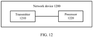
- FIG. 12 is a schematic structural diagram of a network device according to another embodiment of this application. It should be understood that the network device 1200 shown in FIG. 12 is only an example; and the network device in this embodiment of this application may further include another module or unit, or may include modules with functions similar to those of modules in FIG. 12 .
- the processor 1220 may be configured to implement the operations or steps that can be implemented by the processing module 1020 in FIG. 10
- a receiver 1210 may be configured to implement the operations or steps that can be implemented by the communications module 1010 in FIG. 10 .
- the network device shown in FIG. 12 may further include a transmitter, configured to send information to another device.
- the receiver and the transmitter may be integrated together as a transceiver.
- the network device shown in FIG. 12 may further include a memory, configured to store program code executed by the processor.
- the memory may be integrated into the processor 1220.
- the disclosed system, apparatus, and method may be implemented in other manners.
- the described apparatus embodiment is merely an example.
- the unit division is merely logical function division and may be other division in actual implementation.
- a plurality of units or components may be combined or integrated into another system, or some features may be ignored or not performed.
- the displayed or discussed mutual couplings or direct couplings or communication connections may be implemented through some interfaces.
- the indirect couplings or communication connections between the apparatuses or units may be implemented in electronic, mechanical, or other forms.
- the units described as separate parts may or may not be physically separate, and parts displayed as units may or may not be physical units, may be located in one position, or may be distributed on a plurality of network units. Some or all of the units may be selected based on actual requirements to achieve the objectives of the solutions of the embodiments.
- function units in the embodiments of this application may be integrated into one processing unit, or each of the units may exist alone physically, or two or more units are integrated into one unit.
- All or some of the foregoing embodiments may be implemented by software, hardware, firmware, or any combination thereof.
- the embodiments may be implemented completely or partially in a form of a computer program product.
- the computer program product includes one or more computer instructions.
- the computer program instruction When the computer program instruction is loaded and executed on a computer, the procedure or functions according to the embodiments of this application are all or partially generated.
- the computer may be a general-purpose computer, a special-purpose computer, a computer network, or another programmable apparatus.
- the computer instruction may be stored in a computer-readable storage medium or may be transmitted from a computer-readable storage medium to another computer-readable storage medium.
- the computer instruction may be transmitted from a website, computer, server, or data center to another website, computer, server, or data center in a wired (for example, a coaxial cable, an optical fiber, or a digital subscriber line (DSL)) or wireless (for example, infrared, radio, or microwave) manner.
- the computer-readable storage medium may be any usable medium accessible by a computer, or a data storage device, such as a server or a data center, integrating one or more usable media.
- the usable medium may be a magnetic medium (for example, a floppy disk, a hard disk, or a magnetic tape), an optical medium (for example, DVD), or a semiconductor medium (for example, a solid-state drive Solid State Disk (SSD)), or the like.
- a magnetic medium for example, a floppy disk, a hard disk, or a magnetic tape
- an optical medium for example, DVD
- a semiconductor medium for example, a solid-state drive Solid State Disk (SSD)
Landscapes
- Engineering & Computer Science (AREA)
- Signal Processing (AREA)
- Computer Networks & Wireless Communication (AREA)
- Physics & Mathematics (AREA)
- Discrete Mathematics (AREA)
- General Physics & Mathematics (AREA)
- Mathematical Physics (AREA)
- Mobile Radio Communication Systems (AREA)
Applications Claiming Priority (2)
| Application Number | Priority Date | Filing Date | Title |
|---|---|---|---|
| CN201710313853.4A CN108809589A (zh) | 2017-05-05 | 2017-05-05 | 通信方法、终端和网络设备 |
| PCT/CN2018/085651 WO2018202145A1 (zh) | 2017-05-05 | 2018-05-04 | 通信方法、终端和网络设备 |
Publications (3)
| Publication Number | Publication Date |
|---|---|
| EP3614605A1 true EP3614605A1 (de) | 2020-02-26 |
| EP3614605A4 EP3614605A4 (de) | 2020-04-29 |
| EP3614605B1 EP3614605B1 (de) | 2023-10-18 |
Family
ID=64015868
Family Applications (1)
| Application Number | Title | Priority Date | Filing Date |
|---|---|---|---|
| EP18794038.2A Active EP3614605B1 (de) | 2017-05-05 | 2018-05-04 | Kommunikationsverfahren, endgerät und netzwerkvorrichtung |
Country Status (4)
| Country | Link |
|---|---|
| US (1) | US11109365B2 (de) |
| EP (1) | EP3614605B1 (de) |
| CN (1) | CN108809589A (de) |
| WO (1) | WO2018202145A1 (de) |
Cited By (1)
| Publication number | Priority date | Publication date | Assignee | Title |
|---|---|---|---|---|
| EP4170946A1 (de) * | 2021-10-22 | 2023-04-26 | Panasonic Intellectual Property Corporation of America | Benutzergerät und basisstation mit beteiligung an der übertragung von uplink-steuerinformationen |
Families Citing this family (5)
| Publication number | Priority date | Publication date | Assignee | Title |
|---|---|---|---|---|
| CN111615142B (zh) * | 2019-04-30 | 2023-09-22 | 维沃移动通信有限公司 | 信道状态信息csi报告的传输方法、终端及网络设备 |
| CN114598365B (zh) * | 2020-12-01 | 2023-10-17 | 维沃移动通信有限公司 | 传输方法、装置、设备及可读存储介质 |
| CN115913466A (zh) * | 2021-08-26 | 2023-04-04 | 华为技术有限公司 | 数据传输的方法和装置 |
| CN120417070A (zh) * | 2024-01-31 | 2025-08-01 | 华为技术有限公司 | 上行数据传输方法及通信装置 |
| CN120434760A (zh) * | 2024-02-02 | 2025-08-05 | 维沃移动通信有限公司 | 上行传输方法、装置、设备及存储介质 |
Family Cites Families (15)
| Publication number | Priority date | Publication date | Assignee | Title |
|---|---|---|---|---|
| CN102571138B (zh) * | 2005-12-20 | 2015-02-11 | Lg电子株式会社 | 产生码序列的方法及使用其来发送信号的方法 |
| CN101247166A (zh) * | 2007-02-16 | 2008-08-20 | 北京三星通信技术研究有限公司 | 传输调度请求信息的设备和方法 |
| CN101227261B (zh) * | 2008-02-04 | 2013-02-27 | 中兴通讯股份有限公司 | 一种物理混合重传指示信道资源的分配方法 |
| KR101829831B1 (ko) * | 2010-05-06 | 2018-02-19 | 엘지전자 주식회사 | 무선 통신 시스템에서 제어 정보의 전송 방법 및 장치 |
| US20130128821A1 (en) * | 2011-11-18 | 2013-05-23 | Nokia Siemens Networks Oy | Demodulation Reference Signal Arrangement For Uplink Coordinated Multi-Point Reception |
| US9516637B2 (en) * | 2012-05-31 | 2016-12-06 | Lg Electronics Inc. | Method for transceiving control signals, and apparatus therefor |
| CN110838891B (zh) * | 2012-08-03 | 2022-09-16 | 苹果公司 | 用于上行链路控制信息传输的方法、设备和介质 |
| WO2014155494A1 (ja) * | 2013-03-25 | 2014-10-02 | 富士通株式会社 | 無線通信システム、基地局、無線通信装置および無線通信方法 |
| US9635621B2 (en) * | 2014-01-17 | 2017-04-25 | Samsung Electronics Co., Ltd. | Adaptations of dual connectivity operation to UE capability |
| EP3697158B1 (de) * | 2014-03-30 | 2021-12-08 | LG Electronics Inc. | Verfahren zum senden/empfangen von downlink-steuerinformationen in einem drahtloskommunikationssystem mit unterstützung von vorrichtung-zu-vorrichtung-kommunikation und einrichtung dafür |
| CN112118078B (zh) * | 2014-11-14 | 2024-02-27 | 株式会社Ntt都科摩 | 终端、通信系统以及反馈方法 |
| JP2018503293A (ja) | 2014-12-08 | 2018-02-01 | エルジー エレクトロニクス インコーポレイティド | 5個を超えるセルをキャリアアグリゲーションによって使用する時のpucch送信方法及びユーザ装置 |
| US10326493B2 (en) * | 2015-05-13 | 2019-06-18 | Samsung Electronics Co., Ltd. | Control channel transmission and frequency error correction |
| JP2019145865A (ja) * | 2016-07-05 | 2019-08-29 | シャープ株式会社 | 基地局装置、端末装置およびその通信方法 |
| US10873423B2 (en) * | 2018-02-15 | 2020-12-22 | Huawei Technologies Co., Ltd. | Systems and methods for allocation of uplink control channel resources in unlicensed spectrum |
-
2017
- 2017-05-05 CN CN201710313853.4A patent/CN108809589A/zh active Pending
-
2018
- 2018-05-04 WO PCT/CN2018/085651 patent/WO2018202145A1/zh not_active Ceased
- 2018-05-04 EP EP18794038.2A patent/EP3614605B1/de active Active
-
2019
- 2019-11-05 US US16/674,239 patent/US11109365B2/en active Active
Cited By (2)
| Publication number | Priority date | Publication date | Assignee | Title |
|---|---|---|---|---|
| EP4170946A1 (de) * | 2021-10-22 | 2023-04-26 | Panasonic Intellectual Property Corporation of America | Benutzergerät und basisstation mit beteiligung an der übertragung von uplink-steuerinformationen |
| WO2023066914A1 (en) * | 2021-10-22 | 2023-04-27 | Panasonic Intellectual Property Corporation Of America | User equipment and base station involved in transmission of uplink control information |
Also Published As
| Publication number | Publication date |
|---|---|
| US11109365B2 (en) | 2021-08-31 |
| US20200077384A1 (en) | 2020-03-05 |
| EP3614605A4 (de) | 2020-04-29 |
| WO2018202145A1 (zh) | 2018-11-08 |
| EP3614605B1 (de) | 2023-10-18 |
| CN108809589A (zh) | 2018-11-13 |
Similar Documents
| Publication | Publication Date | Title |
|---|---|---|
| EP3614605B1 (de) | Kommunikationsverfahren, endgerät und netzwerkvorrichtung | |
| US8413001B2 (en) | Determining hybrid automatic repeat request (HARQ) timing | |
| US12237960B2 (en) | Terminal, base station, transmission method, and reception method | |
| KR102364995B1 (ko) | 정보 전송 방법 및 장치 | |
| RU2770685C1 (ru) | Терминал и способ передачи | |
| EP2985936B1 (de) | Verfahren zur übertragung von steuerungsinformationen sowie sende- und empfangsvorrichtung | |
| EP4271091B1 (de) | Verfahren und vorrichtung zur sequenzbasierten signalverarbeitung | |
| US9608843B2 (en) | Multiple-input multiple-output orthogonal frequency division multiplexing communication system and method for signal compensation | |
| US9401793B2 (en) | Method and apparatus for encoding uplink control information | |
| KR20100020411A (ko) | 무선 통신 시스템에서 sr 전송 방법 | |
| EP4170984A1 (de) | Datenmodulationsverfahren und -vorrichtung, vorrichtung und speichermedium | |
| EP3866354B1 (de) | Verfahren und vorrichtung zur sequenzbasierten signalverarbeitung | |
| EP3567819B1 (de) | Verfahren, vorrichtung und system zur verwendung in der drahtlosen kommunikation | |
| JP5904709B2 (ja) | コミュニケーションシステムにおけるデータ変調 | |
| CN103873220A (zh) | 一种pucch的信号检测方法及设备 | |
| WO2018171636A1 (zh) | 一种无线通信中的信号发送方法、接收方法、装置和系统 | |
| US10680783B2 (en) | Method and apparatus for transmitting uplink control signal | |
| EP3713134B1 (de) | Pucch-übertragungsverfahren, endgerät und netzwerkseitige vorrichtung | |
| CN114884639B (zh) | 一种信息接收方法、装置和存储介质 | |
| CN115174001B (zh) | 一种nr5g中dmrs符号空闲re的使用方法、存储介质及电子设备 | |
| US20240380550A1 (en) | Data processing method and apparatus, and related device | |
| CN115278910A (zh) | 一种被用于无线通信的节点中的方法和装置 | |
| WO2017194572A1 (en) | Scalable spucch design for low latency lte operation |
Legal Events
| Date | Code | Title | Description |
|---|---|---|---|
| STAA | Information on the status of an ep patent application or granted ep patent |
Free format text: STATUS: THE INTERNATIONAL PUBLICATION HAS BEEN MADE |
|
| PUAI | Public reference made under article 153(3) epc to a published international application that has entered the european phase |
Free format text: ORIGINAL CODE: 0009012 |
|
| STAA | Information on the status of an ep patent application or granted ep patent |
Free format text: STATUS: REQUEST FOR EXAMINATION WAS MADE |
|
| 17P | Request for examination filed |
Effective date: 20191120 |
|
| AK | Designated contracting states |
Kind code of ref document: A1 Designated state(s): AL AT BE BG CH CY CZ DE DK EE ES FI FR GB GR HR HU IE IS IT LI LT LU LV MC MK MT NL NO PL PT RO RS SE SI SK SM TR |
|
| AX | Request for extension of the european patent |
Extension state: BA ME |
|
| A4 | Supplementary search report drawn up and despatched |
Effective date: 20200401 |
|
| RIC1 | Information provided on ipc code assigned before grant |
Ipc: H04L 5/00 20060101AFI20200326BHEP Ipc: H04L 27/26 20060101ALN20200326BHEP |
|
| DAV | Request for validation of the european patent (deleted) | ||
| DAX | Request for extension of the european patent (deleted) | ||
| STAA | Information on the status of an ep patent application or granted ep patent |
Free format text: STATUS: EXAMINATION IS IN PROGRESS |
|
| 17Q | First examination report despatched |
Effective date: 20210412 |
|
| GRAP | Despatch of communication of intention to grant a patent |
Free format text: ORIGINAL CODE: EPIDOSNIGR1 |
|
| STAA | Information on the status of an ep patent application or granted ep patent |
Free format text: STATUS: GRANT OF PATENT IS INTENDED |
|
| RIC1 | Information provided on ipc code assigned before grant |
Ipc: H04L 27/26 20060101ALN20230418BHEP Ipc: H04L 5/00 20060101AFI20230418BHEP |
|
| INTG | Intention to grant announced |
Effective date: 20230517 |
|
| GRAS | Grant fee paid |
Free format text: ORIGINAL CODE: EPIDOSNIGR3 |
|
| GRAA | (expected) grant |
Free format text: ORIGINAL CODE: 0009210 |
|
| STAA | Information on the status of an ep patent application or granted ep patent |
Free format text: STATUS: THE PATENT HAS BEEN GRANTED |
|
| AK | Designated contracting states |
Kind code of ref document: B1 Designated state(s): AL AT BE BG CH CY CZ DE DK EE ES FI FR GB GR HR HU IE IS IT LI LT LU LV MC MK MT NL NO PL PT RO RS SE SI SK SM TR |
|
| REG | Reference to a national code |
Ref country code: GB Ref legal event code: FG4D |
|
| REG | Reference to a national code |
Ref country code: CH Ref legal event code: EP |
|
| REG | Reference to a national code |
Ref country code: IE Ref legal event code: FG4D |
|
| REG | Reference to a national code |
Ref country code: DE Ref legal event code: R096 Ref document number: 602018059645 Country of ref document: DE |
|
| REG | Reference to a national code |
Ref country code: LT Ref legal event code: MG9D |
|
| REG | Reference to a national code |
Ref country code: NL Ref legal event code: MP Effective date: 20231018 |
|
| REG | Reference to a national code |
Ref country code: AT Ref legal event code: MK05 Ref document number: 1623450 Country of ref document: AT Kind code of ref document: T Effective date: 20231018 |
|
| PG25 | Lapsed in a contracting state [announced via postgrant information from national office to epo] |
Ref country code: NL Free format text: LAPSE BECAUSE OF FAILURE TO SUBMIT A TRANSLATION OF THE DESCRIPTION OR TO PAY THE FEE WITHIN THE PRESCRIBED TIME-LIMIT Effective date: 20231018 |
|
| PG25 | Lapsed in a contracting state [announced via postgrant information from national office to epo] |
Ref country code: GR Free format text: LAPSE BECAUSE OF FAILURE TO SUBMIT A TRANSLATION OF THE DESCRIPTION OR TO PAY THE FEE WITHIN THE PRESCRIBED TIME-LIMIT Effective date: 20240119 |
|
| PG25 | Lapsed in a contracting state [announced via postgrant information from national office to epo] |
Ref country code: IS Free format text: LAPSE BECAUSE OF FAILURE TO SUBMIT A TRANSLATION OF THE DESCRIPTION OR TO PAY THE FEE WITHIN THE PRESCRIBED TIME-LIMIT Effective date: 20240218 |
|
| PG25 | Lapsed in a contracting state [announced via postgrant information from national office to epo] |
Ref country code: LT Free format text: LAPSE BECAUSE OF FAILURE TO SUBMIT A TRANSLATION OF THE DESCRIPTION OR TO PAY THE FEE WITHIN THE PRESCRIBED TIME-LIMIT Effective date: 20231018 |
|
| PG25 | Lapsed in a contracting state [announced via postgrant information from national office to epo] |
Ref country code: AT Free format text: LAPSE BECAUSE OF FAILURE TO SUBMIT A TRANSLATION OF THE DESCRIPTION OR TO PAY THE FEE WITHIN THE PRESCRIBED TIME-LIMIT Effective date: 20231018 |
|
| PG25 | Lapsed in a contracting state [announced via postgrant information from national office to epo] |
Ref country code: ES Free format text: LAPSE BECAUSE OF FAILURE TO SUBMIT A TRANSLATION OF THE DESCRIPTION OR TO PAY THE FEE WITHIN THE PRESCRIBED TIME-LIMIT Effective date: 20231018 |
|
| PG25 | Lapsed in a contracting state [announced via postgrant information from national office to epo] |
Ref country code: LT Free format text: LAPSE BECAUSE OF FAILURE TO SUBMIT A TRANSLATION OF THE DESCRIPTION OR TO PAY THE FEE WITHIN THE PRESCRIBED TIME-LIMIT Effective date: 20231018 Ref country code: IS Free format text: LAPSE BECAUSE OF FAILURE TO SUBMIT A TRANSLATION OF THE DESCRIPTION OR TO PAY THE FEE WITHIN THE PRESCRIBED TIME-LIMIT Effective date: 20240218 Ref country code: GR Free format text: LAPSE BECAUSE OF FAILURE TO SUBMIT A TRANSLATION OF THE DESCRIPTION OR TO PAY THE FEE WITHIN THE PRESCRIBED TIME-LIMIT Effective date: 20240119 Ref country code: ES Free format text: LAPSE BECAUSE OF FAILURE TO SUBMIT A TRANSLATION OF THE DESCRIPTION OR TO PAY THE FEE WITHIN THE PRESCRIBED TIME-LIMIT Effective date: 20231018 Ref country code: BG Free format text: LAPSE BECAUSE OF FAILURE TO SUBMIT A TRANSLATION OF THE DESCRIPTION OR TO PAY THE FEE WITHIN THE PRESCRIBED TIME-LIMIT Effective date: 20240118 Ref country code: AT Free format text: LAPSE BECAUSE OF FAILURE TO SUBMIT A TRANSLATION OF THE DESCRIPTION OR TO PAY THE FEE WITHIN THE PRESCRIBED TIME-LIMIT Effective date: 20231018 Ref country code: PT Free format text: LAPSE BECAUSE OF FAILURE TO SUBMIT A TRANSLATION OF THE DESCRIPTION OR TO PAY THE FEE WITHIN THE PRESCRIBED TIME-LIMIT Effective date: 20240219 |
|
| PG25 | Lapsed in a contracting state [announced via postgrant information from national office to epo] |
Ref country code: SE Free format text: LAPSE BECAUSE OF FAILURE TO SUBMIT A TRANSLATION OF THE DESCRIPTION OR TO PAY THE FEE WITHIN THE PRESCRIBED TIME-LIMIT Effective date: 20231018 Ref country code: RS Free format text: LAPSE BECAUSE OF FAILURE TO SUBMIT A TRANSLATION OF THE DESCRIPTION OR TO PAY THE FEE WITHIN THE PRESCRIBED TIME-LIMIT Effective date: 20231018 Ref country code: PL Free format text: LAPSE BECAUSE OF FAILURE TO SUBMIT A TRANSLATION OF THE DESCRIPTION OR TO PAY THE FEE WITHIN THE PRESCRIBED TIME-LIMIT Effective date: 20231018 Ref country code: NO Free format text: LAPSE BECAUSE OF FAILURE TO SUBMIT A TRANSLATION OF THE DESCRIPTION OR TO PAY THE FEE WITHIN THE PRESCRIBED TIME-LIMIT Effective date: 20240118 Ref country code: LV Free format text: LAPSE BECAUSE OF FAILURE TO SUBMIT A TRANSLATION OF THE DESCRIPTION OR TO PAY THE FEE WITHIN THE PRESCRIBED TIME-LIMIT Effective date: 20231018 Ref country code: HR Free format text: LAPSE BECAUSE OF FAILURE TO SUBMIT A TRANSLATION OF THE DESCRIPTION OR TO PAY THE FEE WITHIN THE PRESCRIBED TIME-LIMIT Effective date: 20231018 |
|
| PG25 | Lapsed in a contracting state [announced via postgrant information from national office to epo] |
Ref country code: DK Free format text: LAPSE BECAUSE OF FAILURE TO SUBMIT A TRANSLATION OF THE DESCRIPTION OR TO PAY THE FEE WITHIN THE PRESCRIBED TIME-LIMIT Effective date: 20231018 |
|
| REG | Reference to a national code |
Ref country code: DE Ref legal event code: R097 Ref document number: 602018059645 Country of ref document: DE |
|
| PG25 | Lapsed in a contracting state [announced via postgrant information from national office to epo] |
Ref country code: CZ Free format text: LAPSE BECAUSE OF FAILURE TO SUBMIT A TRANSLATION OF THE DESCRIPTION OR TO PAY THE FEE WITHIN THE PRESCRIBED TIME-LIMIT Effective date: 20231018 |
|
| PG25 | Lapsed in a contracting state [announced via postgrant information from national office to epo] |
Ref country code: SK Free format text: LAPSE BECAUSE OF FAILURE TO SUBMIT A TRANSLATION OF THE DESCRIPTION OR TO PAY THE FEE WITHIN THE PRESCRIBED TIME-LIMIT Effective date: 20231018 |
|
| PG25 | Lapsed in a contracting state [announced via postgrant information from national office to epo] |
Ref country code: SM Free format text: LAPSE BECAUSE OF FAILURE TO SUBMIT A TRANSLATION OF THE DESCRIPTION OR TO PAY THE FEE WITHIN THE PRESCRIBED TIME-LIMIT Effective date: 20231018 Ref country code: SK Free format text: LAPSE BECAUSE OF FAILURE TO SUBMIT A TRANSLATION OF THE DESCRIPTION OR TO PAY THE FEE WITHIN THE PRESCRIBED TIME-LIMIT Effective date: 20231018 Ref country code: RO Free format text: LAPSE BECAUSE OF FAILURE TO SUBMIT A TRANSLATION OF THE DESCRIPTION OR TO PAY THE FEE WITHIN THE PRESCRIBED TIME-LIMIT Effective date: 20231018 Ref country code: IT Free format text: LAPSE BECAUSE OF FAILURE TO SUBMIT A TRANSLATION OF THE DESCRIPTION OR TO PAY THE FEE WITHIN THE PRESCRIBED TIME-LIMIT Effective date: 20231018 Ref country code: EE Free format text: LAPSE BECAUSE OF FAILURE TO SUBMIT A TRANSLATION OF THE DESCRIPTION OR TO PAY THE FEE WITHIN THE PRESCRIBED TIME-LIMIT Effective date: 20231018 Ref country code: DK Free format text: LAPSE BECAUSE OF FAILURE TO SUBMIT A TRANSLATION OF THE DESCRIPTION OR TO PAY THE FEE WITHIN THE PRESCRIBED TIME-LIMIT Effective date: 20231018 Ref country code: CZ Free format text: LAPSE BECAUSE OF FAILURE TO SUBMIT A TRANSLATION OF THE DESCRIPTION OR TO PAY THE FEE WITHIN THE PRESCRIBED TIME-LIMIT Effective date: 20231018 |
|
| PLBE | No opposition filed within time limit |
Free format text: ORIGINAL CODE: 0009261 |
|
| STAA | Information on the status of an ep patent application or granted ep patent |
Free format text: STATUS: NO OPPOSITION FILED WITHIN TIME LIMIT |
|
| 26N | No opposition filed |
Effective date: 20240719 |
|
| PG25 | Lapsed in a contracting state [announced via postgrant information from national office to epo] |
Ref country code: SI Free format text: LAPSE BECAUSE OF FAILURE TO SUBMIT A TRANSLATION OF THE DESCRIPTION OR TO PAY THE FEE WITHIN THE PRESCRIBED TIME-LIMIT Effective date: 20231018 |
|
| PG25 | Lapsed in a contracting state [announced via postgrant information from national office to epo] |
Ref country code: SI Free format text: LAPSE BECAUSE OF FAILURE TO SUBMIT A TRANSLATION OF THE DESCRIPTION OR TO PAY THE FEE WITHIN THE PRESCRIBED TIME-LIMIT Effective date: 20231018 |
|
| REG | Reference to a national code |
Ref country code: DE Ref legal event code: R119 Ref document number: 602018059645 Country of ref document: DE |
|
| REG | Reference to a national code |
Ref country code: CH Ref legal event code: PL |
|
| PG25 | Lapsed in a contracting state [announced via postgrant information from national office to epo] |
Ref country code: MC Free format text: LAPSE BECAUSE OF FAILURE TO SUBMIT A TRANSLATION OF THE DESCRIPTION OR TO PAY THE FEE WITHIN THE PRESCRIBED TIME-LIMIT Effective date: 20231018 |
|
| PG25 | Lapsed in a contracting state [announced via postgrant information from national office to epo] |
Ref country code: LU Free format text: LAPSE BECAUSE OF NON-PAYMENT OF DUE FEES Effective date: 20240504 |
|
| PG25 | Lapsed in a contracting state [announced via postgrant information from national office to epo] |
Ref country code: MC Free format text: LAPSE BECAUSE OF FAILURE TO SUBMIT A TRANSLATION OF THE DESCRIPTION OR TO PAY THE FEE WITHIN THE PRESCRIBED TIME-LIMIT Effective date: 20231018 Ref country code: LU Free format text: LAPSE BECAUSE OF NON-PAYMENT OF DUE FEES Effective date: 20240504 Ref country code: CH Free format text: LAPSE BECAUSE OF NON-PAYMENT OF DUE FEES Effective date: 20240531 |
|
| REG | Reference to a national code |
Ref country code: BE Ref legal event code: MM Effective date: 20240531 |
|
| PG25 | Lapsed in a contracting state [announced via postgrant information from national office to epo] |
Ref country code: DE Free format text: LAPSE BECAUSE OF NON-PAYMENT OF DUE FEES Effective date: 20241203 |
|
| PG25 | Lapsed in a contracting state [announced via postgrant information from national office to epo] |
Ref country code: IE Free format text: LAPSE BECAUSE OF NON-PAYMENT OF DUE FEES Effective date: 20240504 |
|
| PG25 | Lapsed in a contracting state [announced via postgrant information from national office to epo] |
Ref country code: BE Free format text: LAPSE BECAUSE OF NON-PAYMENT OF DUE FEES Effective date: 20240531 |
|
| PG25 | Lapsed in a contracting state [announced via postgrant information from national office to epo] |
Ref country code: FR Free format text: LAPSE BECAUSE OF NON-PAYMENT OF DUE FEES Effective date: 20240531 |
|
| PGFP | Annual fee paid to national office [announced via postgrant information from national office to epo] |
Ref country code: GB Payment date: 20250401 Year of fee payment: 8 |
|
| PG25 | Lapsed in a contracting state [announced via postgrant information from national office to epo] |
Ref country code: CY Free format text: LAPSE BECAUSE OF FAILURE TO SUBMIT A TRANSLATION OF THE DESCRIPTION OR TO PAY THE FEE WITHIN THE PRESCRIBED TIME-LIMIT; INVALID AB INITIO Effective date: 20180504 |
|
| PG25 | Lapsed in a contracting state [announced via postgrant information from national office to epo] |
Ref country code: HU Free format text: LAPSE BECAUSE OF FAILURE TO SUBMIT A TRANSLATION OF THE DESCRIPTION OR TO PAY THE FEE WITHIN THE PRESCRIBED TIME-LIMIT; INVALID AB INITIO Effective date: 20180504 |
|
| PG25 | Lapsed in a contracting state [announced via postgrant information from national office to epo] |
Ref country code: FI Free format text: LAPSE BECAUSE OF FAILURE TO SUBMIT A TRANSLATION OF THE DESCRIPTION OR TO PAY THE FEE WITHIN THE PRESCRIBED TIME-LIMIT Effective date: 20231019 |