EP3614782A1 - Procédé de transmission de données et dispositif de communication - Google Patents
Procédé de transmission de données et dispositif de communication Download PDFInfo
- Publication number
- EP3614782A1 EP3614782A1 EP18809858.6A EP18809858A EP3614782A1 EP 3614782 A1 EP3614782 A1 EP 3614782A1 EP 18809858 A EP18809858 A EP 18809858A EP 3614782 A1 EP3614782 A1 EP 3614782A1
- Authority
- EP
- European Patent Office
- Prior art keywords
- communications device
- frequency
- data
- mode
- instruction
- Prior art date
- Legal status (The legal status is an assumption and is not a legal conclusion. Google has not performed a legal analysis and makes no representation as to the accuracy of the status listed.)
- Granted
Links
Images



Classifications
-
- H—ELECTRICITY
- H04—ELECTRIC COMMUNICATION TECHNIQUE
- H04L—TRANSMISSION OF DIGITAL INFORMATION, e.g. TELEGRAPHIC COMMUNICATION
- H04L1/00—Arrangements for detecting or preventing errors in the information received
- H04L1/08—Arrangements for detecting or preventing errors in the information received by repeating transmission, e.g. Verdan system
-
- H—ELECTRICITY
- H04—ELECTRIC COMMUNICATION TECHNIQUE
- H04L—TRANSMISSION OF DIGITAL INFORMATION, e.g. TELEGRAPHIC COMMUNICATION
- H04L1/00—Arrangements for detecting or preventing errors in the information received
- H04L1/0001—Systems modifying transmission characteristics according to link quality, e.g. power backoff
- H04L1/0023—Systems modifying transmission characteristics according to link quality, e.g. power backoff characterised by the signalling
- H04L1/0025—Transmission of mode-switching indication
-
- H—ELECTRICITY
- H04—ELECTRIC COMMUNICATION TECHNIQUE
- H04L—TRANSMISSION OF DIGITAL INFORMATION, e.g. TELEGRAPHIC COMMUNICATION
- H04L5/00—Arrangements affording multiple use of the transmission path
- H04L5/0001—Arrangements for dividing the transmission path
- H04L5/0003—Two-dimensional division
- H04L5/0005—Time-frequency
- H04L5/0007—Time-frequency the frequencies being orthogonal, e.g. OFDM(A) or DMT
-
- H—ELECTRICITY
- H04—ELECTRIC COMMUNICATION TECHNIQUE
- H04L—TRANSMISSION OF DIGITAL INFORMATION, e.g. TELEGRAPHIC COMMUNICATION
- H04L5/00—Arrangements affording multiple use of the transmission path
- H04L5/003—Arrangements for allocating sub-channels of the transmission path
- H04L5/0053—Allocation of signalling, i.e. of overhead other than pilot signals
-
- H—ELECTRICITY
- H04—ELECTRIC COMMUNICATION TECHNIQUE
- H04W—WIRELESS COMMUNICATION NETWORKS
- H04W24/00—Supervisory, monitoring or testing arrangements
- H04W24/02—Arrangements for optimising operational condition
-
- H—ELECTRICITY
- H04—ELECTRIC COMMUNICATION TECHNIQUE
- H04W—WIRELESS COMMUNICATION NETWORKS
- H04W72/00—Local resource management
- H04W72/04—Wireless resource allocation
- H04W72/044—Wireless resource allocation based on the type of the allocated resource
- H04W72/0453—Resources in frequency domain, e.g. a carrier in FDMA
-
- H—ELECTRICITY
- H04—ELECTRIC COMMUNICATION TECHNIQUE
- H04W—WIRELESS COMMUNICATION NETWORKS
- H04W72/00—Local resource management
- H04W72/20—Control channels or signalling for resource management
- H04W72/21—Control channels or signalling for resource management in the uplink direction of a wireless link, i.e. towards the network
-
- H—ELECTRICITY
- H04—ELECTRIC COMMUNICATION TECHNIQUE
- H04W—WIRELESS COMMUNICATION NETWORKS
- H04W72/00—Local resource management
- H04W72/20—Control channels or signalling for resource management
- H04W72/23—Control channels or signalling for resource management in the downlink direction of a wireless link, i.e. towards a terminal
-
- H—ELECTRICITY
- H04—ELECTRIC COMMUNICATION TECHNIQUE
- H04W—WIRELESS COMMUNICATION NETWORKS
- H04W72/00—Local resource management
- H04W72/50—Allocation or scheduling criteria for wireless resources
- H04W72/53—Allocation or scheduling criteria for wireless resources based on regulatory allocation policies
Definitions
- the present invention relates to the communications field, and in particular, to a data transmission method and a communications device.
- a 5th generation new radio 5th generation new radio, 5G NR for short
- a higher frequency band such as 15 GHz, 28 GHz, 38 GHz, 60 GHz, or 70 GHz.
- a high frequency signal has a low distortion rate, and has advantages such as relatively strong recoverability and a strong anti-interference capability.
- the high frequency signal is different from a low frequency signal, and a path loss of the high frequency signal is very large, resulting in a limitation on a coverage distance.
- a transmission time interval bundling transmission time interval (transmission time interval, TTI Bundling for short) technology is proposed for a physical uplink shared channel (physical uplink shared channel, PUSCH for short) in a long term evolution (long term evolution, LTE for short) system.
- a basic unit of physical layer scheduling in LTE is 1 ms.
- BLER block error rate
- a data packet is repeatedly transmitted on a plurality of consecutive transmission time interval (TTI) resources through TTI bundling, and a receive end combines data on the plurality of TTI resources to improve transmission quality, so as to overcome an edge coverage limitation.
- Embodiments of the present invention provide a data transmission method and a communications device, to enhance coverage, and in particular, to enhance coverage of a high frequency signal.
- the data transmission method is applied to a communications device.
- the communications device is a base station.
- the communications device may be alternatively user equipment.
- an embodiment of the present invention provides a data transmission method, including: obtaining, by a first communications device, a transmission mode instruction, where the transmission mode instruction is used to instruct to use a frequency-domain repetition mode to transmit data, the first communications device may be a base station or user equipment, and the frequency-domain repetition mode means that same data is repeatedly transmitted on different frequency-domain resources; determining, by the first communications device, the frequency-domain repetition mode based on the transmission mode instruction; and performing, by the first communications device, data transmission with a second communications device in the frequency-domain repetition mode.
- a same transport block is repeatedly transmitted in frequency domain, to improve demodulation performance and enhance signal coverage.
- the performing, by the first communications device, data transmission with a second communications device in the frequency-domain repetition mode may include: sending, by the first communications device, data to the second communications device in the frequency-domain repetition mode, or receiving, by the first communications device, data sent by the second communications device in the frequency-domain repetition mode.
- the data generation method may be applied to sending of uplink data, and for example, the uplink data is data sent by user equipment to a base station.
- the data transmission method may also be applied to sending of downlink data, and the downlink data is data sent by a base station to user equipment.
- a specific implementation in which the first communications device obtains the transmission mode instruction may be: receiving the transmission mode instruction sent by the second communications device. For example, the second communications device determines that the first communications device should be instructed to use the frequency-domain repetition mode to transmit data. Then, the second communications device generates the transmission mode instruction, the second communications device sends the transmission mode instruction to the first communications device, and the first communications device obtains the transmission mode instruction.
- a specific manner in which the first communications device obtains the transmission mode instruction is: generating, by the first communications device, the transmission mode instruction.
- the first communications device first determines whether to use the frequency-domain repetition mode to send data, and generate the transmission mode instruction when the first communications device determines to use the frequency-domain repetition mode to send the data.
- the second communications device may instruct the first communications device to use the frequency-domain repetition mode to send the data, or the first communications device may autonomously determine to use the frequency-domain repetition mode to send the data. This increases an applicable scenario of the solution.
- the communications device sends the data in the frequency-domain repetition mode, so that demodulation performance of a channel can be improved, thereby increasing a coverage distance of a system.
- the first communications device after the first communications device generates the transmission mode instruction, the first communications device sends the transmission mode instruction to the second communications device, and the transmission mode instruction is used to instruct to use the frequency-domain repetition mode to transmit data.
- the first communications device sends the transmission mode instruction to the second communications device, and the transmission mode instruction indicates that the first communications device is to use the frequency-domain repetition mode to send data to the second communications device, to instruct the second communications device to use a corresponding manner to receive the data.
- the transmission mode instruction is used to instruct the second communications device to use the frequency-domain repetition mode to send data to the first communications device.
- the first communications device may dynamically send the transmission mode instruction to the second communications device.
- the first communications device may instruct the second communications device to use the frequency-domain repetition mode to send the data. This enhances real-time quality.
- the first communications device may send the transmission mode instruction through semi-static signaling.
- the first communications device configures the second communications device. The first communications device may periodically instruct the second communications device to use the frequency-domain repetition mode to send the data. This reduces signaling overheads.
- a specific manner in which the first communications device determines whether to use the frequency-domain repetition mode to send the data include: determining, by the first communications device based on at least one of the following information: a measured value of a reference signal, and/or channel quality indicator CQI information, and/or modulation and coding scheme MCS information, whether to use the frequency-domain repetition mode to transmit the data.
- the transmission mode instruction includes an indication identifier
- the frequency-domain repetition mode includes at least two repetition manners
- the indication identifier has a corresponding mapping relationship with the repetition manners
- the determining, by the first communications device, the frequency-domain repetition mode based on the transmission mode instruction may specifically include: determining, by the first communications device, the repetition manner in the frequency-domain repetition mode based on the indication identifier in the transmission mode and the mapping relationship, a repetition multiple (such as double repetition or quadruple repetition) and a continuous mapping status, such as continuous resource mapping or discontinuous resource mapping, of resource scheduling in each repeated data block.
- the repetition manner in the frequency-domain repetition mode may exist in a form of a resource mapping pattern of a repeated data block.
- the first communications device and the second communications device may specifically agree on the repetition manners in the frequency-domain repetition mode.
- the first communications device determines the repetition manner in the frequency-domain repetition mode based on the indication identifier in the transmission mode and the mapping relationship.
- the first communications device may determine the specific repetition manner based on a current channel status, to make demodulation performance optimal.
- an embodiment of the present invention provides a computer storage medium, configured to store a computer software instruction used by the foregoing communications device.
- the computer software instruction includes a program designed for performing the foregoing aspect.
- an embodiment of the present invention provides a communications device that has a function performed by the first communications device in the foregoing method.
- the function may be implemented by using hardware, or may be implemented by hardware executing corresponding software.
- the hardware or the software includes one or more modules corresponding to the foregoing function.
- a structure of a communications device includes a memory, a transceiver, and a processor.
- the memory is configured to store computer executable program code, and is coupled to the transceiver.
- the program code includes an instruction, and when the processor executes the instruction, the instruction enables the registration server to execute information or an instruction in the foregoing method.
- Embodiments of the present invention provide a data transmission method and a communications device, to enhance coverage, and in particular, to enhance coverage of a high frequency signal.
- FIG. 1 is a schematic architectural diagram of a data transmission system according to an embodiment of the present invention.
- the data transmission system includes a first communications device 110 and a second communications device 120.
- the first communications device 110 may be a macro base station, a base station to which a cell belongs or a transmission node to which a cell belongs, a micro base station, a small cell, a pico base station, a gNodeB in future 5G, or the like.
- the second communications device 120 may be user equipment (user equipment, UE), customer premises equipment (customer premise equipment, CPE for short) customer premises equipment, access user equipment, a subscriber unit, a subscriber station, a mobile station, a mobile console, a remote station, remote user equipment, a mobile device, a wireless communications device, a user agent, or a user apparatus.
- user equipment user equipment
- CPE customer premise equipment
- the access user equipment may be a cellular phone, a cordless phone, a session initiation protocol (session initiation protocol, SIP for short) phone, a personal digital assistant (personal digital assistant, PDA for short), a handheld device having a wireless communication function, a computing device or another processing device connected to a wireless modem, a vehicle-mounted device, a wearable device, user equipment in a future 5G network, or the like.
- a session initiation protocol session initiation protocol, SIP for short
- PDA personal digital assistant
- the first communications device 110 may be user equipment, customer premises equipment, or the like
- the second communications device 120 is a macro base station, a base station to which a cell belongs or a transmission node to which a cell belongs, a micro base station, a small cell, a pico base station, a gNodeB in future 5G, or the like.
- FIG. 1 an example in which the first communications device is user equipment and the second communications device is a base station is used for description. It should be noted that the schematic architectural diagram shown in FIG. 1 is only an example enumerated for this embodiment of the present invention for ease of description and does not constitute a limitation on the description of the present invention.
- a single high-frequency cell in a wireless communications system may be used as an example.
- An application scenario of the single high-frequency cell is used as an example for description in FIG. 1 .
- the first communications device obtains a transmission mode instruction, where the first communications device may be a base station or user equipment, the transmission mode instruction is used to instruct the first communications device to use a frequency-domain repetition mode to transmit data, and the frequency-domain repetition mode means that same data is repeatedly transmitted on different frequency-domain resources.
- the first communications device determines the frequency-domain repetition mode based on the transmission mode instruction.
- the first communications device performs data transmission with the second communications device in the frequency-domain repetition mode.
- a same transport block is repeatedly transmitted in frequency domain, to directly improve demodulation performance and enhance coverage.
- the method may be applied to sending of uplink data, and the uplink data is data sent by user equipment to a base station.
- the method may also be applied to sending of downlink data, and the downlink data is data sent by a base station to user equipment.
- FIG. 2 is a schematic diagram of a resource grid.
- a transmission signal is distributed and arranged in time domain and frequency domain in a form of a time-frequency resource grid, and a resource element (Resource Element, RE for short) is a basic composition element in the time-frequency resource grid and is a minimum resource unit used for uplink data transmission and downlink data transmission.
- RE resource Element
- a unit for describing resource mapping is a resource block (Resource Block, RB for short), and one RB includes N sc RB ⁇ N symb DL resource elements.
- N symb DL represents a quantity of orthogonal frequency division multiplexing (Orthogonal Frequency Division Multiplexing, OFDM for short) symbols in each slot
- N sc RB represents a quantity of subcarriers in each resource block.
- a resource block group (Resource Block group, RBG for short) is a basic unit of traffic channel resource allocation, and includes a group of RBs.
- a quantity of RBs included in the RBG is related to system bandwidth.
- a frequency-domain repetition mode means that same data is repeatedly transmitted on different frequency-domain resources.
- a same transport block transport block, TB for short
- RBGs RBGs
- a sounding reference signal (Sounding Reference Signal, SRS for short) is an uplink reference signal, is reported by UE to a base station, and is used by the base station to measure quality of an uplink channel, estimate frequency-domain information of the uplink channel, and perform frequency-domain selective scheduling.
- SRS Sounding Reference Signal
- a demodulation reference signal (Demodulation Reference Signal, DMRS for short) is used for related demodulation of an uplink control channel and an uplink data channel.
- a reference signal received power (reference signal receiving power, RSRP for short) is an average value of signal powers received on all REs of a reference signal carried in a symbol, and is a parameter that can represent strength of a radio signal in an LTE network.
- a channel quality indicator (Channel Quality Indicator, CQI for short) is used to reflect channel quality of a physical downlink shared channel (Physical downlink shared channel, PDSCH for short). For example, 0 to 15 may be used to represent the channel quality of the PDSCH, where 0 represents poorest channel quality, and 15 represents best channel quality.
- User equipment sends a CQI to a base station on a physical uplink control channel (Physical Uplink Control Channel, PUCCH for short) PUCCH or a physical uplink shared channel (physical uplink shared channel, PUSCH for short).
- the base station obtains CQI information and can determine current quality of a wireless channel.
- an embodiment of a data transmission method provided in an embodiment of the present invention includes the following steps.
- a first communications device is user equipment and a second communications device is a base station is used for description.
- an application scenario of a single high-frequency cell is used as an example.
- the user equipment sends uplink data to the base station in the high-frequency cell in a frequency-domain repetition mode.
- Step 301 The user equipment obtains a transmission mode instruction, where the transmission mode instruction is used to instruct the user equipment to use the frequency-domain repetition mode to send data, and the frequency-domain repetition mode means that same data is repeatedly sent on different frequency-domain resources.
- the transmission mode instruction is generated by the base station, and then the base station sends the transmission mode to the user equipment.
- the base station sends the transmission mode instruction by using a physical downlink control channel (physical downlink control channel, PDCCH for short) or semi-static signaling, and the transmission mode instruction is used to instruct the user equipment to use the frequency-domain repetition mode to send the data.
- a determining method used by the base station to determine to use the frequency-domain repetition mode includes at least one of the following manners.
- the base station may determine, based on MCS information of an uplink PUSCH, whether to trigger the user equipment to use the frequency-domain repetition mode to send the data. For example, if the MCS information exceeds a preset range, it indicates that the physical transmission rate is relatively low, and the base station determines to trigger the user equipment to use the frequency-domain repetition mode to send the data.
- the base station dynamically sends the transmission mode instruction to the user equipment.
- the base station may instruct the user equipment to use the frequency-domain repetition mode to send the data. This enhances real-time quality.
- the base station sends the transmission mode instruction by using the semi-static signaling.
- the base station configures the user equipment.
- the base station may periodically instruct the user equipment to use the frequency-domain repetition mode to send the data. This reduces signaling overheads.
- a specific manner in which the base station sends the transmission mode instruction to the user equipment is not limited.
- the transmission mode instruction is generated by the user equipment.
- the user equipment may determine whether to use the frequency-domain repetition mode to send the data to the base station.
- a determining method used by the user equipment to determine whether to use the frequency-domain repetition mode includes at least one of the following manners.
- the user equipment needs to dynamically or semi-statically send a message to the base station.
- the message is used to notify the base station that the user equipment prepares to use the frequency-domain repetition mode to send the data to the base station.
- Step 302 The user equipment determines the frequency-domain repetition mode based on the transmission mode instruction.
- the user equipment determines, based on the transmission mode instruction, that the user equipment needs to use the frequency-domain repetition mode to send the data to the base station.
- the transmission mode instruction includes an indication identifier
- the frequency-domain repetition mode includes at least two repetition manners
- the indication identifier has a corresponding mapping relationship with the repetition manners.
- the user equipment determines the repetition manner in the frequency-domain repetition mode based on the indication identifier in the transmission mode and the mapping relationship.
- the repetition manner in the frequency-domain repetition mode may specifically include a repetition multiple (such as double repetition or quadruple repetition) and a continuous mapping status, such as continuous resource mapping or discontinuous resource mapping, of resource scheduling in each repeated data block.
- a repetition multiple such as double repetition or quadruple repetition
- a continuous mapping status such as continuous resource mapping or discontinuous resource mapping, of resource scheduling in each repeated data block.
- FIG. 4 and FIG. 5 are schematic diagram of continuous resource mapping of frequency-domain repetition data blocks
- FIG. 5 is a schematic diagram of discontinuous resource mapping of frequency-domain repetition data blocks.
- cells in a sequence are different frequency-domain resources, and marks of different shapes are used to identify data blocks.
- double repetition is used as an example for description. It can be learned from FIG.
- the repetition manner in the frequency-domain repetition mode may exist in a form of a resource mapping pattern of a repeated data block.
- the indication identifier may include “1", “2", or “3".
- “1” represents double repetition and a continuous mapping manner
- “2" represents quadruple repetition and a discontinuous mapping manner.
- the indication identifier may include two types: a first identifier used to represent a repetition multiple (such as “1” or "2") and a second identifier used to represent a mapping manner (such as "a” or "b"). Combinations of a value included in the first identifier and a value included in the second identifier jointly represent different repetition manners.
- the repetition manner may be alternatively represented by using one type of identifier.
- the indication identifier For example, if the indication identifier is "1", the indication identifier represents double repetition.
- the identifier represents double repetition and continuous mapping, or the like.
- the user equipment and the base station pre-agree, by using a protocol, on the frequency-domain repetition mode and the repetition manners included in the frequency-domain repetition mode.
- the foregoing indication identifier is only an example for ease of description and does not constitute a limitation on the description of the present invention.
- the first communications device and the second communications device may specifically agree on the repetition manners in the frequency-domain repetition mode.
- the first communications device determines the repetition manner in the frequency-domain repetition mode based on the indication identifier in the transmission mode and the mapping relationship.
- the first communications device may determine the specific repetition manner based on a current channel status, to make demodulation performance optimal.
- Step 303 The user equipment sends a first indication message to the base station, where the first indication message is used to indicate that the user equipment is to use the frequency-domain repetition mode to transmit the data.
- the user equipment may directly perform step 304 without performing step 303.
- Step 304 The user equipment sends the data to the base station in the frequency-domain repetition mode.
- the user equipment sends the uplink data to the base station in the frequency-domain repetition mode.
- the user equipment may determine a specific repetition manner based on the indication identifier, to send the uplink data to the base station.
- the user equipment may transmit data of different frequency-domain repetition blocks by weighting the data with different dynamic precoding or PMI codebooks, so as to better match channels on different frequency bands, thereby improving demodulation performance.
- Step 305 The base station performs joint demodulation on the data in the frequency-domain repetition mode, to obtain demodulated data.
- the base station extracts a plurality of repeated data blocks in the frequency-domain repetition mode or the specific repetition manner in the frequency-domain resource mode for combined receiving, combines the repeated resource blocks to perform joint multiple-input multiple-output (multiple-input multiple-output, MIMO for short) equalization, and then performs demodulation, channel decoding, and the like, to perform joint demodulation on the data, so as to obtain the demodulated data.
- MIMO multiple-input multiple-output
- the base station may instruct the user equipment to use the frequency-domain repetition mode to send the uplink data, or the user equipment may autonomously determine to use the frequency-domain repetition mode to send the uplink data. Then, the user equipment sends the data in the frequency-domain repetition mode, so that demodulation performance of a PUSCH channel can be improved, thereby increasing a coverage distance of a system.
- 2 dB to 4 dB coverage enhancement can be achieved through transmission based on double repetition
- 5 dB to 8 dB coverage enhancement can be achieved through transmission based on quadruple repetition.
- the first communications device is the user equipment
- the second communications device is the base station
- the user equipment sends the uplink data to the base station.
- the following provides a description by using an example in which a first communications device is a base station, a second communications device is user equipment, and the base station sends downlink data to the user equipment.
- FIG. 6 another embodiment of a data transmission method provided in an embodiment of the present invention includes the following steps.
- Step 601 The base station obtains a transmission mode instruction, where the transmission mode instruction is used to instruct the base station to use a frequency-domain repetition mode to transmit data, and the frequency-domain repetition mode means that same data is repeatedly transmitted on different frequency-domain resources.
- the base station obtains the transmission mode instruction: 1. generating the transmission mode instruction by the base station; and 2. receiving the transmission mode instruction sent by the user equipment.
- the transmission mode instruction is generated by the base station, and the base station is to use the frequency-domain repetition mode to send the downlink data to the user equipment.
- a determining method used by the base station to determine to use the frequency-domain repetition mode includes at least one of the following manners.
- the base station may determine, based on MCS information of a downlink PUSCH, whether to trigger the user equipment to use the frequency-domain repetition mode to send the data.
- the transmission mode instruction is sent by the user equipment.
- the user equipment may determine to instruct the base station to use the frequency-domain repetition mode to send the data to the base station.
- a determining method used by the user equipment to determine whether to use the frequency-domain repetition mode includes at least one of the following manners.
- the user equipment determines that the base station needs to use the frequency-domain repetition mode to transmit the data
- the user equipment then sends a message to the base station.
- the user equipment needs to dynamically or semi-statically send the message to the base station.
- the message is used to notify the base station that the base station needs to use the frequency-domain repetition mode to send the downlink data to the user equipment.
- Step 602 The base station determines the frequency-domain repetition mode based on the transmission mode instruction.
- the base station determines, based on the transmission mode instruction, that the base station needs to use the frequency-domain repetition mode to send the downlink data to the user equipment.
- the transmission mode instruction includes an indication identifier
- the frequency-domain repetition mode includes at least two repetition manners
- the indication identifier has a corresponding mapping relationship with the repetition manners.
- the base station determines the repetition manner in the frequency-domain repetition mode based on the indication identifier in the transmission mode and the mapping relationship.
- the repetition manner in the frequency-domain repetition mode may specifically include a repetition multiple (such as double repetition or quadruple repetition) and a continuous mapping status, such as continuous resource mapping or discontinuous resource mapping, of resource scheduling in each repeated data block.
- a repetition multiple such as double repetition or quadruple repetition
- a continuous mapping status such as continuous resource mapping or discontinuous resource mapping, of resource scheduling in each repeated data block.
- Step 603 The base station sends a second indication message to the user equipment, where the second indication message is used to indicate that the base station is to use the frequency-domain repetition mode to transmit the data.
- the base station may directly perform step 604 without performing step 603.
- Step 604 The base station performs data transmission with the user equipment in the frequency-domain repetition mode.
- the base station sends the downlink data to the user equipment in the frequency-domain repetition mode.
- the base station may determine a specific repetition manner based on the indication identifier, to send the downlink data to the user equipment.
- the base station may transmit data of different frequency-domain repetition blocks by weighting the data with different dynamic precoding or PMI codebooks, so as to better match channels on different frequency bands, thereby improving demodulation performance.
- Step 605 The user equipment performs joint demodulation on the data in the frequency-domain repetition mode, to obtain demodulated data sent by the base station.
- the user equipment extracts a plurality of repeated data blocks in the frequency-domain repetition mode or the specific repetition manner in the frequency-domain resource mode for combined receiving, combines the repeated resource blocks to perform joint multiple-input multiple-output (multiple-input multiple-output, MIMO for short) equalization, and then performs demodulation, channel decoding, and the like, to perform joint demodulation on the data, so as to obtain the demodulated data sent by the base station.
- MIMO multiple-input multiple-output
- the base station may autonomously determine to use the frequency-domain repetition mode to send the downlink data; or the base station may receive the transmission mode instruction sent by the user equipment, and the base station determines, based on the received transmission mode instruction, to use the frequency-domain repetition mode to send the downlink data. Then, the base station sends the data in the frequency-domain repetition mode, so that demodulation performance of a downlink channel can be improved, thereby increasing a coverage distance of a system.
- FIG. 7 shows an embodiment of a communications device 700 according to an embodiment of the present invention, and the communications device 700 includes:
- the data transmission module 703 further includes a sending unit 7031 and a receiving unit 7032.
- the sending unit 7031 is configured to send data to the second communications device in the frequency-domain repetition mode.
- the receiving unit 7032 is configured to receive data sent by the second communications device in the frequency-domain repetition mode.
- the instruction obtaining module 701 is further configured to receive an indication instruction sent by the second communications device.
- another embodiment of a communications device 800 provided in an embodiment of the present invention includes: the instruction obtaining module 701 that includes a determining unit 7011 and a generation unit 7012.
- the determining unit 7011 is configured to determine whether to use the frequency-domain repetition mode to send data.
- the generation unit 7012 is configured to generate the transmission mode instruction when the determining unit 7011 determines to use the frequency-domain repetition mode to send the data.
- FIG. 9 another embodiment of a communications device 900 provided in an embodiment of the present invention includes: a sending module 704.
- the sending module 704 sends the transmission mode instruction generated by the generation unit 7012 to the second communication, and the transmission mode instruction is used to instruct the second communications device to use the frequency-domain repetition mode to transmit data.
- the determining unit 7011 is further specifically configured to determine, based on at least one of the following information: a measured value of a reference signal, and/or channel quality indicator CQI information, and/or modulation and coding scheme MCS information, whether to use the frequency-domain repetition mode to transmit the data.
- the transmission mode instruction includes an indication identifier
- the frequency-domain repetition mode includes at least two repetition manners
- the indication identifier has a corresponding mapping relationship with the repetition manners.
- the mode determining module is further configured to determine the repetition manner in the frequency-domain repetition mode based on the indication identifier in the transmission mode and the mapping relationship.
- the apparatuses in FIG. 7 to FIG. 9 are presented in a form of functional modules.
- the "module" herein may refer to an application-specific integrated circuit (application-specific integrated circuit, ASIC), a circuit, a processor and a memory that execute one or more software or firmware programs, an integrated logic circuit, and/or another device that can provide the foregoing functions.
- ASIC application-specific integrated circuit
- An embodiment of the present invention further provides another communications device.
- the communications device is user equipment
- the user equipment may include any terminal device such as a mobile phone, a tablet computer, a PDA (Personal Digital Assistant, personal digital assistant), or a vehicle-mounted computer.
- a mobile phone is used.
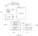
- FIG. 10 is a block diagram of a partial structure of a mobile phone related to a terminal provided in the embodiments of the present invention.
- the mobile phone includes components such as a radio frequency (Radio Frequency, RF) circuit 1010, a memory 1020, an input unit 1030, a display unit 1040, a processor 1080, and a power supply 1090.
- RF Radio Frequency
- FIG. 10 does not constitute a limitation on the mobile phone, and the mobile phone may include more or fewer components than those shown in the figure, may combine some components, or may have different component arrangements.
- the transceiver 1010 may be configured to: receive a signal and send a signal in an information receiving/transmitting process or a call process; in particular, after receiving downlink information from a base station, send the downlink information to the processor 1080 for processing; and send related uplink data to the base station.
- the transceiver 1010 includes but is not limited to an antenna, at least one amplifier, a transceiver, a coupler, a low noise amplifier (Low Noise Amplifier, LNA), a duplexer, or the like.
- the RF circuit 1010 may further communicate with a network and another device through wireless communication.
- the wireless communication may be performed by using any communications standard or protocol, including but not limited to a global system for mobile communications (Global System of Mobile communication, GSM), a general packet radio service (General Packet Radio Service, GPRS), code division multiple access (Code Division Multiple Access, CDMA), wideband code division multiple access (Wideband Code Division Multiple Access, WCDMA), long term evolution (Long Term Evolution, LTE), an email, a short message service (Short Messaging Service, SMS), or the like.
- GSM Global System of Mobile communication
- GPRS General Packet Radio Service
- CDMA Code Division Multiple Access
- WCDMA wideband code division multiple access
- LTE Long Term Evolution
- SMS Short Messaging Service
- the memory 1020 may be configured to store a software program and a module.
- the processor 1080 performs various functional applications of the mobile phone and processes data by running the software program and the module stored in the memory 1020.
- the memory 1020 may mainly include a program storage area and a data storage area.
- the program storage area may store an operating system, an application program required by at least one function (such as a sound play function or an image play function), and the like.
- the data storage area may store data (such as audio data or a phone book) created based on use of the mobile phone, and the like.
- the memory 1020 may include a high-speed random access memory, or may include a nonvolatile memory, for example, at least one magnetic disk storage device, a flash storage device, or another volatile solid-state storage device.
- the input unit 1030 may be configured to: receive entered digital or character information, and generate key signal input related to user setting and function control of the mobile phone.
- the input unit 1030 may include a touch panel 1031 and another input device 1032.
- the touch panel 1031 also referred to as a touchscreen, may collect a touch operation performed by a user on or near the touch panel (for example, an operation performed by the user on or near the touch panel 1031 by using any suitable object or accessory such as a finger or a stylus), and drive a corresponding connection apparatus according to a preset program.
- the touch panel 1031 may include two parts: a touch detection apparatus and a touch controller.
- the touch detection apparatus detects a touch location of the user, detects a signal brought by a touch operation, and delivers the signal to the touch controller.
- the touch controller receives touch information from the touch detection apparatus, converts the touch information into touch point coordinates, and sends the touch point coordinates to the processor 1080.
- the touch controller can receive and execute a command sent by the processor 1080.
- the touch panel 1031 may be implemented by using a plurality of types such as a resistive type, a capacitive type, an infrared type, and a surface acoustic wave type.
- the input unit 1030 may further include the another input device 1032.
- the another input device 1032 may include but is not limited to one or more of a physical keyboard, a function key (such as a volume control key or an on/off key), a trackball, a mouse, and a joystick.
- the display unit 1040 may be configured to display information entered by the user or information provided for the user, and various menus of the mobile phone.
- the display unit 1040 may include a display panel 1041.
- the display panel 1041 may be configured in a form of a liquid crystal display (Liquid Crystal Display, LCD), an organic light-emitting diode (Organic Light-Emitting Diode, OLED), or the like.
- the touch panel 1031 may cover the display panel 1041. After detecting a touch operation on or near the touch panel 1031, the touch panel 1031 delivers the touch operation to the processor 1080, to determine a type of a touch event.
- the processor 1080 provides corresponding visual output on the display panel 1041 based on the type of the touch event.
- the touch panel 1031 and the display panel 1041 are used as two independent components to implement input and input functions of the mobile phone.
- the touch panel 1031 and the display panel 1041 may be integrated to implement the input and output functions of the mobile phone.
- the processor 1080 is a control center of the mobile phone, connects various parts of the entire mobile phone by using various interfaces and lines, and performs various functions of the mobile phone and processes data by running or executing the software program and/or the module stored in the memory 1020 and by invoking data stored in the memory 1020, to perform overall monitoring on the mobile phone.
- the processor 1080 may include one or more processing units.
- an application processor and a modem processor may be integrated into the processor 1080.
- the application processor mainly processes an operating system, a user interface, an application program, and the like.
- the modem processor mainly processes wireless communication. It may be understood that, alternatively, the modem processor may not be integrated into the processor 1080.
- the mobile phone further includes the power supply 1090 (such as a battery) supplying power to each component.
- the power supply may be logically connected to the processor 1080 by using a power management system, to implement functions such as charge and discharge management and power consumption management by using the power management system.
- the mobile phone may further include a camera, a Bluetooth module, and the like. Details are not described herein.
- the processor 1080 and the transceiver 1010 further have the following functions.
- the processor 1080 is configured to obtain a transmission mode instruction, where the transmission mode instruction is used to instruct the first communications device to use a frequency-domain repetition mode to transmit data, and the frequency-domain repetition mode means that same data is repeatedly transmitted on different frequency-domain resources.
- the processor 1080 is used by the first communications device to determine the frequency-domain repetition mode based on the transmission mode instruction.
- the transceiver 1010 is configured to perform data transmission with the second communications device in the frequency-domain repetition mode.
- the transceiver 1010 is further configured to: send data to the second communications device in the frequency-domain repetition mode, or receive data sent by the second communications device in the frequency-domain repetition mode.
- the transceiver 1010 is configured to receive the indication instruction sent by the second communications device.
- the processor 1080 is configured to: determine whether to use the frequency-domain repetition mode to send data, and generate the transmission mode instruction if the processor 1080 determines to use the frequency-domain repetition mode to send the data.
- the transceiver 1010 is further configured to send the transmission mode instruction to the second communication, and the transmission mode instruction is used to instruct the second communications device to use the frequency-domain repetition mode to transmit data.
- the processor 1080 is further used by the first communications device to determine, based on at least one of the following information: a measured value of a reference signal, and/or channel quality indicator CQI information, and/or modulation and coding scheme MCS information, whether to trigger the first communications device to use the frequency-domain repetition mode to transmit the data.
- the transmission mode instruction includes an indication identifier
- the frequency-domain repetition mode includes at least two repetition manners
- the indication identifier has a corresponding mapping relationship with the repetition manners.
- the processor 1080 is further configured to determine the repetition manner in the frequency-domain repetition mode based on the indication identifier in the transmission mode and the mapping relationship.
- An embodiment of the present invention further provides another communications device.
- a base station may be used as an example of the communications device.
- the communications device includes a processor 1101, a memory 1102, and a transceiver 1103.
- FIG. 11 is a schematic structural diagram of a base station according to an embodiment of the present invention.
- the base station 1100 may include one or more processors (central) 1101 and the memory 1102.
- the memory 1132 may perform temporary storage or persistent storage.
- a program stored in the memory 1102 may include one or more modules (not shown in the figure), and each module may include a series of instruction operations for the base station.
- the processor 1101 is configured to enable the base station to perform the method in the foregoing method embodiments.
- a computer readable storage medium stores an instruction.
- the instruction runs on a computer, the computer is enabled to perform the method in the foregoing method embodiments.
- a computer program product including an instruction is provided.
- the computer program product runs on a computer, the computer is enabled to perform the method in the foregoing method embodiments.
- All or some of the foregoing embodiments may be implemented by using software, hardware, firmware, or any combination thereof.
- the embodiments may be implemented completely or partially in a form of a computer program product.
- the computer program product includes one or more computer instructions.
- the computer may be a general-purpose computer, a dedicated computer, a computer network, or other programmable apparatuses.
- the computer instructions may be stored in a computer readable storage medium or may be transmitted from a computer readable storage medium to another computer readable storage medium.
- the computer instructions may be transmitted from a website, computer, server, or data center to another website, computer, server, or data center in a wired (for example, a coaxial cable, an optical fiber, or a digital subscriber line (DSL)) or wireless (for example, infrared, radio, or microwave) manner.
- a wired for example, a coaxial cable, an optical fiber, or a digital subscriber line (DSL)
- wireless for example, infrared, radio, or microwave
- the computer readable storage medium may be any usable medium accessible by a computer, or a data storage device, such as a server or a data center, integrating one or more usable media.
- the usable medium may be a magnetic medium (for example, a floppy disk, a hard disk, or a magnetic tape), an optical medium (for example, a DVD), a semiconductor medium (for example, a solid state disk Solid State Disk (SSD)), or the like.
Landscapes
- Engineering & Computer Science (AREA)
- Signal Processing (AREA)
- Computer Networks & Wireless Communication (AREA)
- Quality & Reliability (AREA)
- Mobile Radio Communication Systems (AREA)
Applications Claiming Priority (2)
| Application Number | Priority Date | Filing Date | Title |
|---|---|---|---|
| CN201710402011.6A CN107359966B (zh) | 2017-05-31 | 2017-05-31 | 一种信号的发射方法及通信设备 |
| PCT/CN2018/078966 WO2018219011A1 (fr) | 2017-05-31 | 2018-03-14 | Procédé de transmission de données et dispositif de communication |
Publications (3)
| Publication Number | Publication Date |
|---|---|
| EP3614782A1 true EP3614782A1 (fr) | 2020-02-26 |
| EP3614782A4 EP3614782A4 (fr) | 2020-04-22 |
| EP3614782B1 EP3614782B1 (fr) | 2026-01-21 |
Family
ID=60272197
Family Applications (1)
| Application Number | Title | Priority Date | Filing Date |
|---|---|---|---|
| EP18809858.6A Active EP3614782B1 (fr) | 2017-05-31 | 2018-03-14 | Procédé de transmission de données et dispositif de communication |
Country Status (5)
| Country | Link |
|---|---|
| US (1) | US11277222B2 (fr) |
| EP (1) | EP3614782B1 (fr) |
| KR (1) | KR20200004356A (fr) |
| CN (1) | CN107359966B (fr) |
| WO (1) | WO2018219011A1 (fr) |
Families Citing this family (10)
| Publication number | Priority date | Publication date | Assignee | Title |
|---|---|---|---|---|
| CN107359966B (zh) * | 2017-05-31 | 2021-01-29 | 上海华为技术有限公司 | 一种信号的发射方法及通信设备 |
| WO2019159274A1 (fr) | 2018-02-15 | 2019-08-22 | 富士通株式会社 | Dispositif de station de base, dispositif terminal, système de communication sans fil, et procédé de communication sans fil |
| WO2019201442A1 (fr) * | 2018-04-19 | 2019-10-24 | Huawei Technologies Co., Ltd. | Dispositif d'émission et dispositif de réception pour communications sans fil |
| WO2019227404A1 (fr) * | 2018-05-31 | 2019-12-05 | 富士通株式会社 | Procédé et dispositif de transmission d'informations de commande |
| US11050525B2 (en) * | 2018-09-27 | 2021-06-29 | Huawei Technologies Co., Ltd. | System and method for control and data channel reliability enhancement using multiple diversity domains |
| CN111182634B (zh) * | 2018-11-22 | 2021-09-14 | 维沃移动通信有限公司 | 数据传输方法、终端及网络设备 |
| CN109792749B (zh) * | 2018-12-19 | 2023-11-28 | 北京小米移动软件有限公司 | 数据调度方法和装置、数据传输方法和装置 |
| CN113381839B (zh) * | 2020-03-09 | 2023-03-14 | 维沃移动通信有限公司 | 信号传输方法、信息发送方法和通信节点 |
| MX2023004664A (es) * | 2020-11-06 | 2023-05-19 | Panasonic Ip Corp America | Dispositivo de comunicacion y metodo de comunicacion. |
| CN114679790A (zh) * | 2022-04-19 | 2022-06-28 | 中国电信股份有限公司 | 信息传输方法、装置及电子设备 |
Family Cites Families (24)
| Publication number | Priority date | Publication date | Assignee | Title |
|---|---|---|---|---|
| EP2107709B8 (fr) * | 2008-04-01 | 2014-08-20 | Innovative Sonic Limited | Procédé et appareil de gestion de regroupement d'intervalle de durée de transmission |
| US9008009B2 (en) | 2009-11-06 | 2015-04-14 | Lg Electronics Inc. | Method of resource block (RB) bundling |
| US9253784B2 (en) | 2010-01-11 | 2016-02-02 | Samsung Electronics Co., Ltd. | Method and system for enabling resource block bundling in LTE-A systems |
| US8917677B2 (en) | 2010-04-14 | 2014-12-23 | Samsung Electronics Co., Ltd. | Systems and methods for bundling resource blocks in a wireless communication system |
| KR20130142932A (ko) * | 2012-06-19 | 2013-12-30 | 한국전자통신연구원 | 무선랜 시스템의 오에프디엠 전송 방법 및 장치 |
| CN103841643B (zh) * | 2012-11-27 | 2017-12-05 | 华为技术有限公司 | 数据传输方法及装置、系统 |
| CN103929266B (zh) * | 2013-01-15 | 2019-08-09 | 中兴通讯股份有限公司 | 控制信道传输、传输处理方法及装置、网络侧设备、终端 |
| US11122520B2 (en) | 2013-09-18 | 2021-09-14 | Qualcomm Incorporated | Coverage enhancements for physical broadcast channel (PBCH) |
| CN104639300B (zh) * | 2013-11-12 | 2017-12-08 | 普天信息技术研究院有限公司 | 一种上行数据传输方法 |
| US9667386B2 (en) | 2013-11-13 | 2017-05-30 | Samsung Electronics Co., Ltd | Transmission of control channel and data channels for coverage enhancements |
| CN110266433B (zh) * | 2014-01-10 | 2022-06-24 | 夏普株式会社 | 物理信道配置方法以及基站和用户设备 |
| WO2016033989A1 (fr) | 2014-09-04 | 2016-03-10 | 华为技术有限公司 | Procédé de transmission d'informations, dispositif côté utilisateur et dispositif côté réseau |
| WO2016163505A1 (fr) * | 2015-04-09 | 2016-10-13 | 株式会社Nttドコモ | Station de base radio, terminal utilisateur et procédé de communication radio |
| CN107079436B (zh) * | 2015-04-10 | 2020-09-04 | 松下电器(美国)知识产权公司 | 无线通信方法、enodeb和用户设备 |
| US10149198B2 (en) * | 2015-04-28 | 2018-12-04 | Qualcomm Incorporated | Techniques for transmitting and/or receiving high efficiency wireless local area network information |
| WO2017078603A1 (fr) * | 2015-11-06 | 2017-05-11 | Telefonaktiebolaget Lm Ericsson (Publ) | Ressource de référence de csi et rapport de cqi pour opération de mtc |
| TW201739182A (zh) * | 2016-03-30 | 2017-11-01 | Idac控股公司 | 在5g系統中進階空間調變系統及方法 |
| CN107371273B (zh) * | 2016-05-13 | 2023-05-30 | 中兴通讯股份有限公司 | 随机接入方法、装置及用户设备 |
| US10512046B2 (en) * | 2016-06-09 | 2019-12-17 | Samsung Electronics Co., Ltd. | Method and apparatus for measurement reference signal and synchronization |
| WO2018093951A1 (fr) * | 2016-11-16 | 2018-05-24 | Intel IP Corporation | Amélioration de couverture pour un internet des objets sans licence (u-ido) |
| WO2018141595A1 (fr) * | 2017-02-06 | 2018-08-09 | Sony Mobile Communications Ab | Procédé et dispositif d'attribution de ressources dans des systèmes radio avec répétition de domaine de fréquence |
| EP3593477A1 (fr) * | 2017-03-07 | 2020-01-15 | Intel IP Corporation | Conception d'informations de commande de liaison descendante en vue d'une amélioration de couverture à large bande |
| CN107359966B (zh) * | 2017-05-31 | 2021-01-29 | 上海华为技术有限公司 | 一种信号的发射方法及通信设备 |
| US11050525B2 (en) * | 2018-09-27 | 2021-06-29 | Huawei Technologies Co., Ltd. | System and method for control and data channel reliability enhancement using multiple diversity domains |
-
2017
- 2017-05-31 CN CN201710402011.6A patent/CN107359966B/zh active Active
-
2018
- 2018-03-14 EP EP18809858.6A patent/EP3614782B1/fr active Active
- 2018-03-14 WO PCT/CN2018/078966 patent/WO2018219011A1/fr not_active Ceased
- 2018-03-14 KR KR1020197035863A patent/KR20200004356A/ko not_active Ceased
-
2019
- 2019-11-26 US US16/696,559 patent/US11277222B2/en active Active
Also Published As
| Publication number | Publication date |
|---|---|
| KR20200004356A (ko) | 2020-01-13 |
| WO2018219011A1 (fr) | 2018-12-06 |
| EP3614782B1 (fr) | 2026-01-21 |
| US20200099468A1 (en) | 2020-03-26 |
| US11277222B2 (en) | 2022-03-15 |
| CN107359966B (zh) | 2021-01-29 |
| CN107359966A (zh) | 2017-11-17 |
| EP3614782A4 (fr) | 2020-04-22 |
Similar Documents
| Publication | Publication Date | Title |
|---|---|---|
| US11277222B2 (en) | Data transmission method and communications device | |
| US11510080B2 (en) | Method and apparatus for triggering multi-beam reporting | |
| US11395267B2 (en) | Wireless communication method, terminal device, and network device | |
| CN110035527B (zh) | 资源指示方法、终端设备和网络设备 | |
| CN110622454B (zh) | 无线通信的方法和装置 | |
| EP3591867B1 (fr) | Procédé et appareil de transmission d'informations | |
| US11539483B2 (en) | Wireless communication method and apparatus | |
| US20190261349A1 (en) | Information transmission method and device | |
| WO2020220330A1 (fr) | Procédé de communication sans fil, dispositif terminal et dispositif de réseau | |
| WO2018228571A1 (fr) | Procédé de communication et appareil de communication | |
| US20140226582A1 (en) | Method and Apparatus for Providing Channel State Information (CSI) Measurement and Reporting for a Segment Carrier | |
| TWI739996B (zh) | 通信方法及終端 | |
| WO2019100905A1 (fr) | Procédé de transmission de données, dispositif terminal et dispositif de réseau | |
| US11381291B2 (en) | Channel state measurement method and apparatus | |
| US20220225337A1 (en) | Interference measurement reporting method and communications apparatus | |
| US12500652B2 (en) | Communication method and apparatus | |
| EP3534658A1 (fr) | Procédé, dispositif et système d'indication de ressource | |
| EP3501226A1 (fr) | Procédé de transmission de signaux de référence d'informations d'état de canal dans de grands systèmes mimo | |
| US11362879B2 (en) | Constellation rotation method and base station | |
| CN115208526B (zh) | 信号传输方法、装置及终端 | |
| WO2018171742A1 (fr) | Procédé et dispositif de communication sans fil |
Legal Events
| Date | Code | Title | Description |
|---|---|---|---|
| STAA | Information on the status of an ep patent application or granted ep patent |
Free format text: STATUS: THE INTERNATIONAL PUBLICATION HAS BEEN MADE |
|
| PUAI | Public reference made under article 153(3) epc to a published international application that has entered the european phase |
Free format text: ORIGINAL CODE: 0009012 |
|
| STAA | Information on the status of an ep patent application or granted ep patent |
Free format text: STATUS: REQUEST FOR EXAMINATION WAS MADE |
|
| 17P | Request for examination filed |
Effective date: 20191120 |
|
| AK | Designated contracting states |
Kind code of ref document: A1 Designated state(s): AL AT BE BG CH CY CZ DE DK EE ES FI FR GB GR HR HU IE IS IT LI LT LU LV MC MK MT NL NO PL PT RO RS SE SI SK SM TR |
|
| AX | Request for extension of the european patent |
Extension state: BA ME |
|
| A4 | Supplementary search report drawn up and despatched |
Effective date: 20200324 |
|
| RIC1 | Information provided on ipc code assigned before grant |
Ipc: H04W 74/08 20090101AFI20200318BHEP Ipc: H04L 1/08 20060101ALI20200318BHEP |
|
| DAV | Request for validation of the european patent (deleted) | ||
| DAX | Request for extension of the european patent (deleted) | ||
| STAA | Information on the status of an ep patent application or granted ep patent |
Free format text: STATUS: EXAMINATION IS IN PROGRESS |
|
| 17Q | First examination report despatched |
Effective date: 20211005 |
|
| GRAP | Despatch of communication of intention to grant a patent |
Free format text: ORIGINAL CODE: EPIDOSNIGR1 |
|
| STAA | Information on the status of an ep patent application or granted ep patent |
Free format text: STATUS: GRANT OF PATENT IS INTENDED |
|
| INTG | Intention to grant announced |
Effective date: 20250902 |
|
| GRAS | Grant fee paid |
Free format text: ORIGINAL CODE: EPIDOSNIGR3 |
|
| GRAA | (expected) grant |
Free format text: ORIGINAL CODE: 0009210 |
|
| STAA | Information on the status of an ep patent application or granted ep patent |
Free format text: STATUS: THE PATENT HAS BEEN GRANTED |
|
| AK | Designated contracting states |
Kind code of ref document: B1 Designated state(s): AL AT BE BG CH CY CZ DE DK EE ES FI FR GB GR HR HU IE IS IT LI LT LU LV MC MK MT NL NO PL PT RO RS SE SI SK SM TR |
|
| REG | Reference to a national code |
Ref country code: CH Ref legal event code: F10 Free format text: ST27 STATUS EVENT CODE: U-0-0-F10-F00 (AS PROVIDED BY THE NATIONAL OFFICE) Effective date: 20260121 |
|
| REG | Reference to a national code |
Ref country code: DE Ref legal event code: R096 Ref document number: 602018088725 Country of ref document: DE |
|
| REG | Reference to a national code |
Ref country code: IE Ref legal event code: FG4D |
|
| PGFP | Annual fee paid to national office [announced via postgrant information from national office to epo] |
Ref country code: DE Payment date: 20260211 Year of fee payment: 9 |