EP3614979B1 - Système de placement à libération proximale et distale - Google Patents
Système de placement à libération proximale et distale Download PDFInfo
- Publication number
- EP3614979B1 EP3614979B1 EP18724672.3A EP18724672A EP3614979B1 EP 3614979 B1 EP3614979 B1 EP 3614979B1 EP 18724672 A EP18724672 A EP 18724672A EP 3614979 B1 EP3614979 B1 EP 3614979B1
- Authority
- EP
- European Patent Office
- Prior art keywords
- stent
- distal
- outer sheath
- sheath
- proximal
- Prior art date
- Legal status (The legal status is an assumption and is not a legal conclusion. Google has not performed a legal analysis and makes no representation as to the accuracy of the status listed.)
- Active
Links
Images


Classifications
-
- A—HUMAN NECESSITIES
- A61—MEDICAL OR VETERINARY SCIENCE; HYGIENE
- A61F—FILTERS IMPLANTABLE INTO BLOOD VESSELS; PROSTHESES; DEVICES PROVIDING PATENCY TO, OR PREVENTING COLLAPSING OF, TUBULAR STRUCTURES OF THE BODY, e.g. STENTS; ORTHOPAEDIC, NURSING OR CONTRACEPTIVE DEVICES; FOMENTATION; TREATMENT OR PROTECTION OF EYES OR EARS; BANDAGES, DRESSINGS OR ABSORBENT PADS; FIRST-AID KITS
- A61F2/00—Filters implantable into blood vessels; Prostheses, i.e. artificial substitutes or replacements for parts of the body; Appliances for connecting them with the body; Devices providing patency to, or preventing collapsing of, tubular structures of the body, e.g. stents
- A61F2/95—Instruments specially adapted for placement or removal of stents or stent-grafts
- A61F2/962—Instruments specially adapted for placement or removal of stents or stent-grafts having an outer sleeve
- A61F2/966—Instruments specially adapted for placement or removal of stents or stent-grafts having an outer sleeve with relative longitudinal movement between outer sleeve and prosthesis, e.g. using a push rod
-
- A—HUMAN NECESSITIES
- A61—MEDICAL OR VETERINARY SCIENCE; HYGIENE
- A61F—FILTERS IMPLANTABLE INTO BLOOD VESSELS; PROSTHESES; DEVICES PROVIDING PATENCY TO, OR PREVENTING COLLAPSING OF, TUBULAR STRUCTURES OF THE BODY, e.g. STENTS; ORTHOPAEDIC, NURSING OR CONTRACEPTIVE DEVICES; FOMENTATION; TREATMENT OR PROTECTION OF EYES OR EARS; BANDAGES, DRESSINGS OR ABSORBENT PADS; FIRST-AID KITS
- A61F2/00—Filters implantable into blood vessels; Prostheses, i.e. artificial substitutes or replacements for parts of the body; Appliances for connecting them with the body; Devices providing patency to, or preventing collapsing of, tubular structures of the body, e.g. stents
- A61F2/82—Devices providing patency to, or preventing collapsing of, tubular structures of the body, e.g. stents
-
- A—HUMAN NECESSITIES
- A61—MEDICAL OR VETERINARY SCIENCE; HYGIENE
- A61F—FILTERS IMPLANTABLE INTO BLOOD VESSELS; PROSTHESES; DEVICES PROVIDING PATENCY TO, OR PREVENTING COLLAPSING OF, TUBULAR STRUCTURES OF THE BODY, e.g. STENTS; ORTHOPAEDIC, NURSING OR CONTRACEPTIVE DEVICES; FOMENTATION; TREATMENT OR PROTECTION OF EYES OR EARS; BANDAGES, DRESSINGS OR ABSORBENT PADS; FIRST-AID KITS
- A61F2/00—Filters implantable into blood vessels; Prostheses, i.e. artificial substitutes or replacements for parts of the body; Appliances for connecting them with the body; Devices providing patency to, or preventing collapsing of, tubular structures of the body, e.g. stents
- A61F2/95—Instruments specially adapted for placement or removal of stents or stent-grafts
- A61F2/962—Instruments specially adapted for placement or removal of stents or stent-grafts having an outer sleeve
- A61F2/966—Instruments specially adapted for placement or removal of stents or stent-grafts having an outer sleeve with relative longitudinal movement between outer sleeve and prosthesis, e.g. using a push rod
- A61F2/9661—Instruments specially adapted for placement or removal of stents or stent-grafts having an outer sleeve with relative longitudinal movement between outer sleeve and prosthesis, e.g. using a push rod the proximal portion of the stent or stent-graft is released first
-
- A—HUMAN NECESSITIES
- A61—MEDICAL OR VETERINARY SCIENCE; HYGIENE
- A61F—FILTERS IMPLANTABLE INTO BLOOD VESSELS; PROSTHESES; DEVICES PROVIDING PATENCY TO, OR PREVENTING COLLAPSING OF, TUBULAR STRUCTURES OF THE BODY, e.g. STENTS; ORTHOPAEDIC, NURSING OR CONTRACEPTIVE DEVICES; FOMENTATION; TREATMENT OR PROTECTION OF EYES OR EARS; BANDAGES, DRESSINGS OR ABSORBENT PADS; FIRST-AID KITS
- A61F2/00—Filters implantable into blood vessels; Prostheses, i.e. artificial substitutes or replacements for parts of the body; Appliances for connecting them with the body; Devices providing patency to, or preventing collapsing of, tubular structures of the body, e.g. stents
- A61F2/95—Instruments specially adapted for placement or removal of stents or stent-grafts
- A61F2/9517—Instruments specially adapted for placement or removal of stents or stent-grafts handle assemblies therefor
-
- A—HUMAN NECESSITIES
- A61—MEDICAL OR VETERINARY SCIENCE; HYGIENE
- A61F—FILTERS IMPLANTABLE INTO BLOOD VESSELS; PROSTHESES; DEVICES PROVIDING PATENCY TO, OR PREVENTING COLLAPSING OF, TUBULAR STRUCTURES OF THE BODY, e.g. STENTS; ORTHOPAEDIC, NURSING OR CONTRACEPTIVE DEVICES; FOMENTATION; TREATMENT OR PROTECTION OF EYES OR EARS; BANDAGES, DRESSINGS OR ABSORBENT PADS; FIRST-AID KITS
- A61F2/00—Filters implantable into blood vessels; Prostheses, i.e. artificial substitutes or replacements for parts of the body; Appliances for connecting them with the body; Devices providing patency to, or preventing collapsing of, tubular structures of the body, e.g. stents
- A61F2/95—Instruments specially adapted for placement or removal of stents or stent-grafts
- A61F2/962—Instruments specially adapted for placement or removal of stents or stent-grafts having an outer sleeve
- A61F2/966—Instruments specially adapted for placement or removal of stents or stent-grafts having an outer sleeve with relative longitudinal movement between outer sleeve and prosthesis, e.g. using a push rod
- A61F2002/9665—Instruments specially adapted for placement or removal of stents or stent-grafts having an outer sleeve with relative longitudinal movement between outer sleeve and prosthesis, e.g. using a push rod with additional retaining means
Definitions
- the disclosure is directed to devices for delivering expandable stents. More particularly, the disclosure is directed to a device that selectively deploys a stent in a distal to proximal or a proximal to distal manner.
- Delivery devices for expandable stents such as those used in endoscopic applications, generally have an outer sheath that retracts to allow the stent to be expanded radially at the target site. Retraction of the outer sheath in the proximal direction exposes the stent in a distal to proximal direction, thus allows the distal end of the stent to be expanded first, providing a distal-to-proximal direction of expansion. This manner of deployment may allow the distal end of the stent to be placed in a particular location. However, the final location of the proximal end of the stent may not be known until the stent is fully expanded, particularly when the stent is self-expanding.
- deploying the stent in a distal-to-proximal manner may require estimation of where the proximal end will reside upon complete expansion of the stent. Such an estimation may not have the desired precision needed for proper placement of the stent.
- US 2011/307049 A1 is related to a bi-directional stent delivery system including an inner elongate shaft, a radially expandable prosthesis disposed over the inner elongate shaft, an outer elongate shaft, and a shuttle sheath disposed over the radially expandable prosthesis.
- the distal portion of the inner shaft is releasably coupled to the distal portion of the shuttle sheath
- the distal portion of the outer shaft is releasably coupled the proximal portion of the shuttle sheath.
- a proximal coupling mechanism couples the distal end of the outer shaft with the proximal end of the shuttle sheath.
- a distal coupling mechanism couples the distal end of the shuttle sheath with the distal end of the inner shaft via a nosecone.
- Distal advancement of the inner shaft advances the shuttle sheath distally when the outer shaft is uncoupled from the shuttle sheath, thereby allowing the prosthesis to radially expand from a proximal end to a distal end.
- Proximal retraction of the outer shaft retracts the shuttle sheath proximally when the inner shaft is uncoupled from the shuttle sheath, thereby allowing the prosthesis to radially expand from a distal end to a proximal end thereof.
- the present invention is directed to a stent delivery system as defined in the claims.
- This disclosure provides design, material, and use alternatives for medical devices, including delivery systems.
- a first example includes a stent delivery system.
- the system includes an elongated inner member extending between a distal tip and a proximal end, a stent surrounding a stent receiving region of the elongated inner member, the stent having a collapsed configuration and an expanded configuration.
- the system also includes an elongated outer sheath slidably disposed over the inner member, the outer sheath extending between a distal end and a proximal end, a stent sheath surrounding the stent to restrain the stent in the collapsed configuration, a proximal junction detachably coupling the distal end of the outer sheath to a proximal end of the stent sheath, the proximal junction being actuatable to selectively uncouple the distal end of the outer sheath from the proximal end of the stent sheath, and a distal junction detachably coupling a distal end of the stent sheath to the distal tip of the inner member, the distal junction being actuatable to selectively uncouple the stent sheath from the distal tip.
- the proximal junction is actuatable by rotating the inner member relative to the outer sheath in a first direction
- the distal junction is actuatable by rotating the inner member relative to the outer sheath in a second direction that is opposite the first direction, and at least a first stent expanding element disposed at at least one of the distal tip or the distal end of the outer sheath, the first stent expanding element having a radially retracted position and a radially elevated position.
- the distal tip includes a proximally extending threaded element
- the distal end of the outer sheath includes a distally extending threaded element
- the stent sheath includes threaded cavities on the distal and proximal ends thereof, the threaded cavities configured to receive the proximally and distally extending threaded elements.
- distally and proximally extending threaded elements are tapered.
- distal and proximal threaded connections are each fully coupled and uncoupled by less than a 360 degree turn.
- the first stent expanding element includes a first elongated member having a first end attached to the proximally extending threaded element on the distal tip or to the distally extending threaded element on the distal end of the outer sheath, the first stent expanding element having a second free end opposite the first end.
- the stent delivery system further includes a first spring biasing the first stent expanding element in the elevated position.
- the first spring is disposed in a first groove extending longitudinally through the threading on the threaded element to which the first elongated member is attached, wherein the first elongated member is disposed within the first groove when the first stent expanding element is in the retracted position.
- the stent delivery system further includes a first slider element extending from a proximal region of the outer sheath to a distal end positioned adjacent the first end of the first elongated member, the first slider element configured to slide over a portion of the first elongated member, moving the first stent expanding element from the elevated position to the retracted position.
- the first stent expanding element is disposed on the distal tip, the system further comprising a second stent expanding element disposed on the distal end of the outer sheath.
- the first stent expanding element has a free end extending proximally and the second stent expanding element has a free end extending distally.
- the first stent expanding element is disposed on the distal tip
- the system further includes a second stent expanding element disposed at the distal end of the outer sheath, the second stent expanding element including a second elongated member having a first end attached to the distally extending threaded element on the distal end of the outer sheath and a second free end opposite its first end, the second stent expanding element having a radially retracted position and a radially elevated position, and a second slider element extending from a proximal region of the outer sheath to a distal end positioned adjacent the first end of the second elongated member, the second slider element configured to slide over a portion of the second elongated member, moving the second stent expanding element from the elevated position to the retracted position.
- the first and second sliders are independently moveable.
- the stent is deployable in a proximal-to-distal manner by uncoupling the proximal junction and moving the distal tip and stent sheath distally together relative to the stent.
- the stent is deployable in a distal-to-proximal manner by uncoupling the distal junction and moving the stent sheath and outer sheath proximally together relative to the stent.
- Another example is a method of selectively deploying a stent in a proximal-to-distal manner or in a distal-to-proximal manner, including advancing a stent delivery system to a target location, the stent delivery system including an elongated inner member extending between a distal tip and a proximal end, a stent surrounding a stent receiving region of the elongated inner member and having a collapsed configuration and an expanded configuration, an elongated outer sheath slidably disposed over the inner member and extending between a distal end and a proximal end, a stent sheath surrounding the stent and removably coupled to the distal tip of the inner member and the distal end of the outer sheath, a first stent expanding element disposed at the distal tip, and a second stent expanding element disposed at the distal end of the outer sheath, the first and second stent expanding elements having a re
- the method further includes deploying the stent in a distal-to-proximal manner by rotating the inner member relative to the outer sheath in a first rotational direction, to selectively decouple a distal end of the stent sheath from the distal tip, and moving the stent sheath coupled to the outer sheath proximally relative to the stent to uncover the stent, wherein moving the stent sheath proximally away from the distal tip causes the first stent expanding element to return to the biased elevated position and hold the stent as the stent sheath is moved proximally away from the stent.
- the method includes deploying the stent in a proximal-to-distal manner by rotating the inner member relative to the outer sheath in a second rotational direction opposite the first rotational direction to selectively decouple the distal end of the outer sheath from a proximal end of the stent sheath, and moving the stent sheath coupled to the distal tip distally relative to the stent to uncover the stent, wherein moving the stent sheath distally away from the distal end of the outer sheath causes the second stent expanding element to return to the biased elevated position and hold the stent as the stent sheath is moved distally away from the stent.
- a stent delivery system including an elongated inner member extending between a distal tip and a proximal end, a stent surrounding a stent receiving region of the elongated inner member, the stent having a collapsed configuration and an expanded configuration, an elongated outer sheath slidably disposed over the inner member, the outer sheath extending between a distal end and a proximal end, a stent sheath surrounding the stent to restrain the stent in the collapsed configuration.
- the system also includes a proximal junction detachably coupling the distal end of the outer sheath to a proximal end of the stent sheath, the proximal junction being actuatable to selectively uncouple the distal end of the outer sheath from the proximal end of the stent sheath, and a distal junction detachably coupling a distal end of the stent sheath to the distal tip of the inner member, the distal junction being actuatable to selectively uncouple the stent sheath from the distal tip.
- the proximal junction is actuatable by rotating the inner member relative to the outer sheath in a first direction
- the distal junction is actuatable by rotating the inner member relative to the outer sheath in a second direction that is opposite the first direction
- a first stent expanding element disposed at the distal tip and a second stent expanding element disposed at the distal end of the outer sheath
- the first and second stent expanding elements each having a radially retracted position and a radially elevated position
- the first stent expanding element includes a first elongated member having a first end attached to the distal tip and a second free end
- the second stent expanding element includes a second elongated member having a first end attached to the distal end of the outer sheath and a second free end
- the first and second stent expanding elements are each biased in the elevated position.
- the stent delivery system further includes a first spring disposed in a first groove extending longitudinally through threading on a threaded element extending proximally from the distal tip, the first spring disposed under the first end of the first elongated member and biasing the first elongated member in the elevated position, wherein the first elongated member is disposed within the first groove when the first stent expanding element is in the retracted position, and a second spring disposed in a second groove extending longitudinally through threading on a threaded element extending distally from the distal end of the outer sheath, the second spring disposed under the first end of the second elongated member and biasing the second elongated member in the elevated position, wherein the second elongated member is disposed within the second groove when the second stent expanding element is in the retracted position.
- the stent delivery system further includes a first slider element extending from a proximal region of the outer sheath to a distal end positioned adjacent the first end of the first elongated member, the first slider element configured to slide over a portion of the first elongated member, moving the first stent expanding element from the elevated position to the retracted position, and a second slider element extending from a proximal region of the outer sheath to a distal end positioned adjacent the first end of the second elongated member, the second slider element configured to slide over a portion of the second elongated member, moving the second stent expanding element from the elevated position to the retracted position.
- the first and second sliders are independently moveable.
- the distal tip includes a proximally extending threaded element
- the distal end of the outer sheath includes a distally extending threaded element
- the stent sheath includes threaded cavities on the distal and proximal ends thereof, the threaded cavities configured to receive the proximally and distally extending threaded elements, wherein the proximally and distally extending threaded elements are each tapered.
- references in the specification to "an embodiment”, “an example”, “some embodiments”, “some examples”, “another embodiment”, “another example” etc. indicate that the embodiment or example described may include one or more particular features, structures, and/or characteristics. However, such recitations do not necessarily mean that all embodiments or examples include the particular features, structures, and/or characteristics. Additionally, when particular features, structures, and/or characteristics are described in connection with one embodiment or example, it should be understood that such features, structures, and/or characteristics may also be used connection with other embodiments and examples whether or not explicitly described unless clearly stated to the contrary.
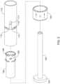
- FIG. 1 illustrates a stent delivery device 100 that includes an outer sheath 110, a stent sheath 105, and an inner member 120 extending through and longitudinally slidable within the stent sheath 105 and the outer sheath 110.
- the inner member 120 may include a distal tip 122 fixed to the distal end thereof.
- the outer sheath 110 may cover the majority of the device 100 excluding a portion of the distal end of the device 100 including the stent sheath 105 and the distal tip 122.
- the outer sheath 110 may be characterized by a flexible tube which includes one or more lumens 114 extending therethrough.
- the proximal ends of the outer sheath 110 and inner member 120 may be attached, or otherwise coupled to components of a handle assembly 150.
- the inner member 120 may be a flexible tube extending through the lumen 114 of the outer sheath 110, and through the hollow tubular stent sheath 105.
- Guidance elements such as pull wires (not shown) may be disposed with the lumen 114, or one or more additional lumens to help navigate the delivery device 100 and/or actuate one or more components of the delivery device 100.
- the device 100 may be sized and configured for use in a range of medical applications, including, but not limited to, vascular applications or gastrointestinal applications, such as biliary, esophageal or colonic applications.
- a proximal end of the inner member 120 may be fixedly attached, or otherwise coupled to a handle 130 of the handle assembly 150.
- the inner member 120 may include a tubular portion extending between a proximal knob 152 and the distal tip 122, with the tubular portion extending through the lumen 114 of the outer sheath 110 and through the stent sheath 105.
- the inner member 120 may include at least one lumen 124, such as a guidewire lumen, extending therethrough.
- lumen 124 may extend through the entire length of the inner member 120 and tip 122.
- the stent delivery device 100 may be routed over a guidewire (not shown), which may be received through the lumen 124.
- the stent sheath 105 may be positioned longitudinally between the outer sheath 110 and the distal tip 122.
- the stent sheath 105 may be removably connected to the distal end 112 of the outer sheath 110 at a proximal junction 145 and removably connected to the proximal end 123 of the distal tip 122 at a distal junction 140, as illustrated in FIG. 1 .
- the removable connection between the stent sheath 105 and the outer sheath 110 and the distal tip 122 may be a threaded connection, for example. In order to allow the proximal junction 145 and distal junction 140 to be separately and independently released, the threading of the connections may be reversed.
- the distal junction 140 may have right hand threading 128 and the proximal junction 145 may have left hand threading 118.
- the distal junction 140 may be released by rotating the inner member 120 (and thus the distal tip 122) via the handle 130 to the right or clockwise relative to the outer sheath 110 and the stent sheath 105.
- the proximal junction 145 may be released by rotating the outer sheath 110 to the right or clockwise relative to the inner member handle 130, the stent sheath 105, the inner member 120, and the distal tip 122.
- the outer sheath 110 may be grasped directly at a proximal end thereof and the inner member 120 may be rotated by grasping and rotating the knob 152 or handle 130.
- the distal junction 140 may have left hand threading 128 and the proximal junction 145 may have right hand threading 118.
- the oppositely threaded distal and proximal junctions 140, 145 allow only one end of the stent sheath 105 (i.e., only one of the junctions) to be disconnected at a time, thus providing either distal-first (i.e., distal-to-proximal) or proximal-first (i.e., proximal-to-distal) delivery of the stent.
- the stent sheath 105 will remain connected to either the inner member 120 (via the distal tip 122) or the outer sheath 110, depending on which junction is separated.
- the handle assembly 150 may include a knob 152 disposed on the proximal end of the inner member 120, as shown in Figure 2 . Rotation of the knob 152 rotates the inner member 120 relative to the outer sheath 110. Rotation may be provided by a circumferential slot 115 in the outer sheath 110, as shown in Figure 3 and discussed below.
- FIG. 3 The elements of one example of a handle assembly 150 are shown in FIG. 3 and include a coupler 154 disposed inside the outer sheath 110 and the handle 130 disposed around the outside of the outer sheath 110.
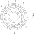
- the handle 130 may have a pin 132 (see Figure 4 ) extending inward.
- the pin 132 may extend through the circumferential slot 115 in the outer sheath 110, through an opening 156 in the wall of the coupler 154 and be fixedly attached to the inner member 120.
- the inner member 120, coupler 154, and handle 130 are moveable together both rotationally and axially. The user may rotate the inner member 120 relative to the outer sheath 110 by rotating either the handle 130 or the knob 152 on the proximal end of the inner member 120.
- the pin 132 travels around the circumferential slot 115 as the handle 130 rotates.
- the circumferential slot 115 is connected to and in communication with the longitudinal channel 111.
- the inner member 120 may be slid axially within the outer sheath 110 by moving either the handle 130 or the knob 152.
- the pin 132 travels along the longitudinal channel 111 as the handle 130 moves axially relative to the outer sheath 110.
- the coupler 154 may have a plurality of finger-like projections 158 extending outward from the outer surface.
- the projections 158 disposed around a first half of the circumference of the coupler 154 are curved in a first direction and the projections 158 disposed around the second half of the circumference are curved in a second direction opposite the first direction, as shown in Figures 3 and 4 .
- the coupler 154 may have at least one set of opposing projections 158. In the example shown in Figure 3 , the coupler 154 has two sets of opposing projections 158, spaced apart along the longitudinal axis of the coupler 154.
- the projections 158 slide along the inner surface of the outer sheath 110 when the coupler 154 is rotated relative to the outer sheath 110.
- the projections 158 may allow the coupler 154 and attached inner member 120 to rotate relative to the outer sheath 110 while maintaining the radial position of the inner member 120 and coupler 154 within the outer sheath 110.
- the projections 158 may be sized to fit between two spaced apart rings of bumps 113 projecting from the inner surface of the outer sheath 110, as shown in Figures 4 and 5 .
- the bumps 113 may extend circumferentially around the inner surface of the outer sheath 110.
- the bumps 113 may be spaced apart from one another circumferentially by a distance sufficient for the projections 158 to pass between adjacent bumps 113 when the coupler 154 is rotated to place the projections 158 between bumps 113, and the inner member 120 with attached coupler 154 is moved distally, as shown in the difference between Figures 5 and 6 .
- a mark 134 such as a dot, circle, line, arrow, or other marking, may be provided on the outer surface of the handle 130, indicating the rotated positions in which the handle 130 and attached inner member 120 may be advanced distally.
- the marked positions are those in which the projections 158 on the coupler 154 are positioned between adjacent bumps 113.
- a different marking 136 may be provided to indicate the start of a 360 degree rotation.
- Figure 5 shows the inner member 120 and attached coupler 154 and handle 130 in the proximal-most position, with the projections 158 disposed between circumferential rings of bumps 113 and axially adjacent to bumps 113.
- the handle 130, coupler 154, and inner member 120 are rotatable relative to the outer sheath 110, but are prevented from moving axially relative to the outer sheath 110 because the projections 158 are disposed axially adjacent the bumps 113.
- the handle 130 When the handle 130 is rotated to a position in which the projections 158 are disposed between circumferentially adjacent bumps 113, the handle 130 may then be moved distally, into the position shown in Figure 6 .
- Figure 7 shows an alternative handle assembly, in which a channel 1111 is disposed longitudinally along the inner member 1120 and the outer sheath 1110 has only a circumferential slot 1115.
- the handle assembly includes a handle 1130 with a pin (not shown) that extends through the circumferential slot 1115 in the outer sheath 1110, through the opening 1156 in the coupler 1154.
- the pin slides along the longitudinal channel 1111 in the inner member 1120, providing the axial movement of the inner member 1120 relative to the outer sheath 1110.
- the outer sheath 1110 may have a proximal knob 1152, and the coupler 154 may have projections 1158 that slide along the inner surface of the outer sheath 1110.
- Rotational movement of the inner member 1120 relative to the outer sheath 1110 is provided by the pin connected to the handle 1130 moving through the circumferential slot 1115.
- the handle 1130 and coupler 1154 move rotationally, but do not move axially relative to the outer sheath 1110.
- Axial movement is provided by moving the inner member 1120, with the pin connected to the handle 1130 sliding along the channel 1111.
- the threaded proximal end 123 of the distal tip 122 and the threaded distal end 112 of the outer sheath 110 may be substantially cylindrical in shape, as shown in Figure 1 .
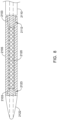
- the threaded proximal end 2123 of the distal tip 2122 on the inner member 2120 and the threaded distal end 2112 of the outer sheath 2110 may both be tapered, with corresponding tapered threaded ends 2103 on each end of the stent sheath 2105, as shown in Figure 8 .
- threaded proximal end 2123 of the distal tip 2122 and the threaded distal end 2112 of the outer sheath 2110 are illustrated as male threaded portions (i.e., external threading), mating with female threaded portions (i.e., internal threading) of the tapered threaded ends 2103 of the stent sheath 2105.
- male and female threading of one or both of the junctions may be reversed, if desired.
- the tapered threaded ends provide for a quick release and reconnection between the threaded distal tip 2122 or outer sheath 2110 and the stent sheath 2105 at the junctions. A reduced number of threads may also be used to provide for quick release.
- a tapered threaded end and/or reduced thread number may provide a device in which the inner member 2120 or outer sheath 2110 may need to be turned one revolution (360 degrees) or less to fully engage or disengage the threaded connection.
- three-fourths of a turn (270 degrees) or less, one-half of a turn (180 degrees) or less, one-fourth of a turn (90 degrees) or less, or less may be needed to fully engage or disengage the threaded connection.
- the inner member 120 may include at least one stent receiving region 126 located along a distal region of the inner member 120 proximal of the distal tip 122.
- a stent 200 may be disposed over and surround the inner member 120 in the stent receiving region 126, such that the inner member 120 extends through the stent 200 and the stent sheath 105 surrounds the stent 200.
- the stent 200 may be a self-expanding stent, configured to automatically expand to an expanded state from a constrained state when the stent sheath 105 is removed from the stent.
- the stent 200 may be made from self-expanding or shape memory alloys such as nitinol, spring steels, resilient polymer, or other materials known in the art for making self-expanding stents.
- the stent sheath 105 may hold the self-expanding stent 200 in its reduced diameter delivery configuration on the stent receiving region 126 until the stent sheath 105 is moved to uncover the stent 200.
- the stent 200 may be manually expanded.
- the stent 200 may have one or more markers (not shown) such as radiopaque markers, disposed on the distal end 210, proximal end 220, or both ends. When markers are present on both the proximal and distal ends 220, 210 of the stent 200, the markers may be the same or different. Additionally, alignment markers (not shown) may be disposed on the outer sheath 110 and/or the inner member 120 to show rotational orientation and/or torqueing of the elements relative to each other. The alignment markers may be radiopaque and may be placed at any location along the length of the device, as desired.
- markers such as radiopaque markers
- the stent 200 may be uncovered by or deployed from the stent sheath 105 by moving the distal tip 122 and the outer sheath 110 longitudinally away from each other. This longitudinal movement may be achieved by either holding the outer sheath 110 stationary and advancing the inner member 120 distally and/or holding the inner member 120 stationary and retracting the outer sheath 110 proximally.
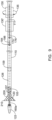
- a stent 200 may be deployed in a distal-to-proximal direction by decoupling (e.g., unscrewing or unthreading) the distal tip 122 from the stent sheath 105 at the distal junction 140 and then withdrawing the outer sheath 110 (along with the stent sheath 105) proximally, as shown in Figure 9 .
- the inner member 120 may be advanced distally, exposing the stent 200 from the distal end of the stent sheath 105.
- the handle 130 may be rotated clockwise to rotate the distal tip 122 clockwise, as indicated by arrow 135 to decouple (e.g., unscrew or unthread) the distal junction 140.
- the outer sheath 110 and the stent sheath 105 may be withdrawn proximally while the handle 130 is held stationary.
- the handle 130 may slide along the longitudinal channel 111 to position 130'.
- the distal end 210 of the stent 200 may be initially uncovered and the stent 200 may expand in a distal-to-proximal direction.
- the inner member 120 and distal tip 122 may be retracted proximally through the expanded stent 200, coupled (e.g., screwed or threaded) back onto the stent sheath 105, and the device 100 may be removed from the patient leaving the stent 200 in place.
- the handle 130 is rotatable relative to the outer sheath 110, to provide rotational motion for the inner member 120 and the distal tip 122.
- the inner member 120 may be advanced and retracted longitudinally relative to the outer sheath 110 by moving the handle 130 along a longitudinal channel 111 in the outer sheath 110 and/or handle assembly 150.
- a portion of the handle 130 extends through the longitudinal channel 111 and is attached to the inner member 120.
- the length of the longitudinal channel 111 may be sufficient to allow the handle 130 to be moved longitudinally to a position where the distal tip 122 is separated from the distal end 107 of the stent sheath 105 by a distance greater than the length of the stent 200.
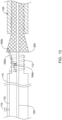
- a stent 200 may be deployed in a proximal-to-distal direction by decoupling (e.g., unscrewing or unthreading) the outer sheath 110 from the stent sheath 105 at the proximal junction 145 and then the inner member 120 (along with the stent sheath 105) may be advanced distally relative to the outer sheath 110, as shown in Figure 10 .
- the outer sheath 110 may be withdrawn proximally, exposing the stent 200 from the proximal end of the stent sheath 105.
- the handle 130 may be rotated counter-clockwise to rotate the stent sheath 105 counter-clockwise, as indicated by arrow 137 to decouple (e.g., unscrew or unthread) the proximal junction 145.
- decouple e.g., unscrew or unthread
- the inner member 120 and attached stent sheath 105 may be moved distally, with the handle 130 moving along the longitudinal channel 111, allowing the outer sheath 110 to remain stationary.
- the outer sheath 110 may be moved proximally.
- the proximal end 220 of the stent 200 may be initially uncovered and the stent 200 may expand in a proximal-to-distal direction.
- the inner member 120, the distal tip 122, and the stent sheath 105 may be retracted proximally through the expanded stent 200, coupled (e.g., screwed or threaded) back onto the outer sheath 110, and the device 100 removed from the patient leaving the stent 200 in place.
- the stent 200 may be self-expandable or it may be manually expanded with a device such as a balloon (not shown).
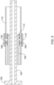
- a stent expander 160a (shown in Figure 14 ) may be provided on the proximal end 123 of the distal tip 122and/or a stent expander 160b (shown in Figure 12 ) may be provided on the distal end 112 of the outer sheath 110.
- Figure 11 illustrates features of the stent expander 160a/160b.
- the stent expander 160a/160b may include an elongate member attached at one end in a channel or groove 166a cut in the threaded distal end 112 of the outer sheath 110 and/or a channel or groove 166b cut in the threaded proximal end 123 of the distal dip 122.
- a second, free end of the stent expander 160a/160b may include an enlarged tip 162a/162b which may be used to adjust the position of the stent 200 upon expansion.
- a spring 164b may be disposed under the stent expander 160b in the groove 166b, which biases the stent expander 160b in the elevated, radially outward position, as shown in Figure 13 .
- the stent expander 160b may be formed of a resilient material, with the stent expander 160b biased to the elevated, radially outward position.
- Figures 12 and 13 illustrate the actuation of the stent expander 160b attached to the distal end 112 of the outer sheath 110. It is noted that the stent expander 160a attached to the proximal end 123 of the distal tip 122 may be configured similarly.
- the stent sheath 105 presses the stent expander 160b down into the groove 166b, compressing the spring 164b so the stent expander 160b does not interfere with the threaded connection between the stent sheath 105 and the distal end 112 of the outer sheath 110.
- the spring 164b expands, returning the stent expander 160b to its biased elevated position and the tip 162b, which may contact an inner surface of the proximal end region of the stent 200 and exerts a radially outwardly directed force on the stent 200, aids the stent 200 in expanding in a proximal-first direction, as shown in Figure 13 .
- the resiliency of the stent expander 160b may cause the stent expander 160b to revert back towards the elevated positioned once unconstrained by the stent sheath 105.
- the stent expander 160b may aid in expanding the stent 200, whether the stent 200 is self-expanding or manually expanded. Further, the tip 162b of the stent expander 160b may be used to move the fully expanded stent 200 if adjustment to the final position of the stent 200 is desired. In some instances, the tip 162b of the stent expander 160b may contact an inner surface of the stent 200 as the stent sheath 105 is moved longitudinally relative to the stent 200 to facilitate deployment of the stent 200 from the stent sheath 105.
- the stent expander 160b must be returned to the collapsed position within the groove 166b.
- this may be accomplished by moving an outer sheath slider 170 distally over the stent expander 160b (e.g., along a radially outward surface of the stent expander 160b), which may push the stent expander 160b radially inward down into the groove 166b.
- the outer sheath slider 170 is in the retracted position, with the distal end of the outer sheath slider 170 just proximal of the stent expander 160b.
- a handle 174 or other actuator that extends through the outer sheath 110 may be connected to the proximal end of the outer sheath slider 170, and configured to be advanced distally to move the outer sheath slider 170 distally along the stent expander 160b.
- the outer sheath slider 170 may be a substantially flat, thin element sufficiently rigid to force the stent expander 160b down into the groove 166b.
- the outer sheath slider 170 may move within a lumen in the outer sheath 110.
- a channel 176 through the wall of the outer sheath 110 and/or the handle assembly 150 wall may allow the handle 174 to move back and forth longitudinally to actuate the outer sheath slider 170.
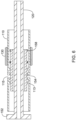
- Figure 14 shows the stent expander 160a attached to the proximal end 123 of the distal tip 122.
- the inner member 120 is shown extended distally away from the stent sheath 105.
- the stent 200 has been removed for clarity.
- the stent expander 160a may be attached at one end in a channel or groove 166a cut in the threaded proximal end 123 of the distal tip 122 with a spring 164a under the stent expander 160a.
- the spring 164a may bias the stent expander 160a in an elevated, radially outward position, as shown in Figure 14 .
- the stent expander 160a may be formed of a resilient material, with the stent expander 160a biased to the elevated, radially outward position.
- An enlarged tip 162a may be attached to or otherwise provided at the free end of the stent expander 160a.
- an inner member slider 180 is disposed within the distal tip 122.
- the inner member slider 180 may be attached to a slider extension 182 that is disposed within a second lumen 125 in the inner member 120, adjacent the guidewire lumen 124.
- the slider extension 182 may be disposed within the guidewire lumen 124.
- the proximal end of the slider extension 182 may be attached to a handle 184 (shown in Figure 15 ) or other actuator that extends through a channel 186 in the outer sheath 110 and/or the handle assembly 150.
- a handle 184 shown in Figure 15
- the inner member slider 180 is distal of the stent expander 160a, as shown in Figure 14 , and the stent expander 160a is in the elevated position.
- the handle 184 is moved proximally, the inner member slider 180 may be moved proximally over the stent expander 160a (e.g., along a radially outward surface of the stent expander 160a), pushing the stent expander 160a down into the groove 166a.
- the inner member slider 180 and slider extension 182 on the distal tip 122 may be a substantially flat, thin element sufficiently rigid to force the stent expander 160a down into the groove 166a on the proximal end 123 of the distal tip 122.
- the stent expander 160a may aid in expanding the stent 200, whether the stent 200 is self-expanding or manually expanded. Further, the tip 162a of the stent expander 160a may be used to move the fully expanded stent 200 if adjustment to the final position of the stent 200 is desired.
- the handle 174 connected to the outer sheath slider 170 is positioned near the distal end of the channel 176, indicating the outer sheath slider 170 is positioned distally over the stent expander 160b and pressing the stent expander 160b into the groove 166b, thereby allowing the stent sheath 105 to slide off the proximal end of the stent 200.
- the handle 184 connected to the inner member slider 180 is also positioned near the distal end of the channel 186, indicating the inner member slider 180 is withdrawn distally of the stent expander 160a, allowing the stent expander 160a to be in the elevated position, as shown in Figure 14 .
- the stent expander 160a is thus in position to aid the stent 200 in expanding in a distal-to-proximal direction.
- the handle 184 may be moved proximally along the channel 186, moving the inner member slider 180 proximally over and pressing the stent expander 160a into the groove 166a.
- the distal tip 122 With the stent expander 160a in the compressed position, the distal tip 122 may be withdrawn proximally through the expanded stent 200.
- the distal tip 122 may then be coupled (e.g., screwed or threaded) back onto the distal end of the stent sheath 105 and the entire device may be withdrawn.
- the spring 164b may expand, returning the stent expander 160b to its biased elevated position and the tip 162b, which may contact an inner surface of the proximal end region of the stent 200 and exerts a radially outwardly directed force on the stent 200, aids the stent 200 in expanding in a proximal-first direction.
- the resiliency of the stent expander 160b may cause the stent expander 160b to revert back towards the elevated positioned once unconstrained by the stent sheath 105.
- the stent expander 160b may aid in expanding the stent 200, whether the stent 200 is self-expanding or manually expanded.
- the tip 162b of the stent expander 160b may be used to move the fully expanded stent 200 if adjustment to the final position of the stent 200 is desired.
- the handle 174 connected to the outer sheath slider 170 is positioned near the proximal end of the channel 176, indicating the outer sheath slider 170 is withdrawn proximally of the stent expander 160b, allowing the stent expander 160b to be in the elevated position, as shown in Figure 13 .
- the stent expander 160b is thus in position to aid the stent 200 in expanding in a proximal-to-distal direction.
- the handle 184 connected to the inner member slider 180 is also positioned near the proximal end of the channel 186, indicating the inner member slider 180 is positioned proximally over the stent expander 160a and pressing the stent expander 160a into the groove 166a, thereby allowing the stent sheath 105 to slide off the distal end of the stent 200.
- the handle 174 may be moved distally along the channel 176, moving the outer sheath slider 170 distally over and pressing the stent expander 160b into the groove 166b.
- the distal tip 122 and attached stent sheath 105 may be withdrawn proximally through the expanded stent 200.
- the distal tip 122 may then be coupled (e.g., screwed or threaded) back onto the distal end of the stent sheath 105 and the entire device may be withdrawn.
- Figure 15 is a top view of the outer sheath 110 and inner member 120, but with the stent sheath 105 and stent 200 removed for clarity. Both the outer sheath slider 170 and inner member slider 180 are extended over their respective stent expanders 160b/160a, forcing the stent expanders 160b/160a into their respective grooves 166b/166a. This is indicated by the position of handles 174 and 184. Handle 174, connected to the outer sheath slider 170, is positioned near the distal end of the channel 176, indicating the outer sheath slider 170 is extended distally over the stent expander 160b on the distal end 112 of the outer sheath 110.
- Handle 184 connected to the inner member slider extension 182, is near the proximal end of the channel 186, indicating the inner member slider 180 is extended proximally over the stent expander 160a on the proximal end 123 of the distal tip 122.
- the device, with a stent 200 loaded therein may be advanced to a target location in a patient in such a configuration. In other instances, the device, with a stent 200 loaded therein, may be advanced to a target location in a patient, with the handles in the opposite positions such that the stent expander 160a and the stent expander 160b are pressed radially outward against an inner surface of the stent 200.
- the user decides whether to deploy the stent 200 in the proximal-to-distal or distal-to-proximal direction, and thereafter actuate either the handle 174 or the handle 184 to facilitate deployment of the stent 200.
- the materials that can be used for the various components of the delivery device 100 (and/or other devices disclosed herein) and the various tubular members disclosed herein may include those commonly associated with medical devices.
- the following discussion makes reference to outer sheath 110 and inner member 120 and other components of device 100.
- this is not intended to limit the devices and methods described herein, as the discussion may be applied to other similar devices and/or components of devices or devices disclosed herein.
- the various components of the devices/systems disclosed herein may include a metal, metal alloy, polymer (some examples of which are disclosed below), a metal-polymer composite, ceramics, combinations thereof, and the like, or other suitable material.
- suitable metals and metal alloys include stainless steel, such as 304V, 304L, and 316LV stainless steel; mild steel; nickel-titanium alloy such as linear-elastic and/or super-elastic nitinol; other nickel alloys such as nickel-chromium-molybdenum alloys (e.g., UNS: N06625 such as INCONEL ® 625, UNS: N06022 such as HASTELLOY ® C-22 ® , UNS: N10276 such as HASTELLOY ® C276 ® , other HASTELLOY ® alloys, and the like), nickel-copper alloys (e.g., UNS: N04400 such as MONEL ® 400, NICKELVAC ® 400
- suitable polymers may include polytetrafluoroethylene (PTFE), ethylene tetrafluoroethylene (ETFE), fluorinated ethylene propylene (FEP), polyoxymethylene (POM, for example, DELRIN ® available from DuPont), polyether block ester, polyurethane (for example, Polyurethane 85A), polypropylene (PP), polyvinylchloride (PVC), polyether-ester (for example, ARNITEL ® available from DSM Engineering Plastics), ether or ester based copolymers (for example, butylene/poly(alkylene ether) phthalate and/or other polyester elastomers such as HYTREL ® available from DuPont), polyamide (for example, DURETHAN ® available from Bayer or CRISTAMID ® available from Elf Atochem), elastomeric polyamides, block polyamide/ethers, polyether block amide (PEBA, for example available under the trade name PEBAX ®
- portions or all of the delivery device 100 and/or other components of delivery system may be doped with, made of, or otherwise include a radiopaque material.
- Radiopaque materials are understood to be materials capable of producing a relatively bright image on a fluoroscopy screen or another imaging technique during a medical procedure. This relatively bright image aids the user of the delivery device 100 in determining its location.
- Some examples of radiopaque materials can include, but are not limited to, gold, platinum, palladium, tantalum, tungsten alloy, polymer material loaded with a radiopaque filler, and the like. Additionally, other radiopaque marker bands and/or coils may also be incorporated into the design of the delivery device 100 to achieve the same result.
Landscapes
- Health & Medical Sciences (AREA)
- Engineering & Computer Science (AREA)
- Biomedical Technology (AREA)
- Cardiology (AREA)
- Oral & Maxillofacial Surgery (AREA)
- Transplantation (AREA)
- Heart & Thoracic Surgery (AREA)
- Vascular Medicine (AREA)
- Life Sciences & Earth Sciences (AREA)
- Animal Behavior & Ethology (AREA)
- General Health & Medical Sciences (AREA)
- Public Health (AREA)
- Veterinary Medicine (AREA)
- Media Introduction/Drainage Providing Device (AREA)
Claims (14)
- Système de pose de stent comprenant :un élément interne allongé (120) s'étendant entre une pointe distale (122) et une extrémité proximale ;un stent (200) entourant une région de réception de stent (126) de l'élément interne allongé (120), le stent (200) ayant une configuration repliée et une configuration déployée ;une gaine externe allongée (110) disposée, de manière coulissante, sur l'élément interne (120), la gaine externe (110) s'étendant entre une extrémité distale (112) et une extrémité proximale,une gaine de stent (105) entourant le stent (200) pour retenir le stent (200) dans la configuration repliée ;une jonction proximale (145) couplant, de manière détachable, l'extrémité distale (112) de la gaine externe (110) à une extrémité proximale de la gaine de stent (105), la jonction proximale (145) pouvant être actionnée pour découpler sélectivement l'extrémité distale (112) de la gaine externe (110) de l'extrémité proximale de la gaine de stent (105) ;une jonction distale (140) couplant, de manière détachable, une extrémité distale de la gaine de stent (105) à la pointe distale (122) de l'élément interne (120), la jonction distale (140) pouvant être actionnée pour découpler, sélectivement, la gaine de stent (105) de la pointe distale (122) ;dans lequel la jonction proximale (145) peut être actionnée en faisant tourner l'élément interne (120) par rapport à la gaine externe (110) dans une première direction, et la jonction distale (140) peut être actionnée en faisant tourner l'élément interne (120) par rapport à la gaine externe (110) dans une deuxième direction qui est opposée à la première direction ; caractérisé par :au moins un premier élément de déploiement de stent fixé à au moins l'une parmi la pointe distale (122) ou l'extrémité distale (112) de la gaine externe (110), le premier élément de déploiement de stent ayant une position radialement rétractée et une position radialement élevée.
- Système de pose de stent selon la revendication 1, dans lequel la pointe distale (122) comprend un élément fileté s'étendant de manière proximale, l'extrémité distale (112) de la gaine externe (110) comprend un élément fileté s'étendant de manière distale, et la gaine de stent (105) comprend des cavités filetées sur ses extrémités distale et proximale, les cavités filetées étant configurées pour recevoir les éléments filetés s'étendant de manière proximale et distale.
- Système de pose de stent selon la revendication 2, dans lequel les éléments filetés s'étendant de manière distale et proximale sont progressivement rétrécis.
- Système de pose de stent selon la revendication 3, dans lequel les raccordements filetés distal et proximal sont chacun complètement couplés et découplés selon une valeur inférieure à une rotation à 360 degrés.
- Système de pose de stent selon l'une quelconque des revendications 2 à 4, dans lequel le premier élément de déploiement de stent comprend un premier élément allongé ayant une première extrémité fixée sur l'élément fileté s'étendant de manière proximale sur la pointe distale (122) ou sur l'élément fileté s'étendant de manière distale sur l'extrémité distale (112) de la gaine externe (110), le premier élément de déploiement de stent ayant une deuxième extrémité libre opposée à la première extrémité.
- Système de pose de stent selon la revendication 5, comprenant en outre un premier ressort (164a, 164b) sollicitant le premier élément de déploiement de stent dans la position élevée.
- Système de pose de stent selon la revendication 6, dans lequel le premier ressort (164a, 164b) est disposé dans une première rainure (166a, 166b) s'étendant longitudinalement à travers le filetage sur l'élément fileté auquel le premier élément allongé est fixé, dans lequel le premier élément allongé est disposé à l'intérieur de la première rainure (166a, 166b) lorsque le premier élément de déploiement de stent est dans la position rétractée.
- Système de pose de stent selon la revendication 7, comprenant en outre un premier élément de glissière s'étendant à partir d'une région proximale de la gaine externe (110) à une extrémité distale positionnée de manière adjacente à la première extrémité du premier élément allongé, le premier élément de glissière étant configuré pour coulisser sur une partie du premier élément allongé, déplaçant le premier élément de déploiement de stent de la position élevée à la position rétractée.
- Système de pose de stent selon l'une quelconque des revendications précédentes, dans lequel le premier élément de déploiement de stent est disposé sur la pointe distale (122), le système comprenant en outre un deuxième élément de déploiement de stent disposé sur l'extrémité distale (112) de la gaine externe (110).
- Système de pose de stent selon la revendication 9, dans lequel le premier élément de déploiement de stent a une extrémité libre s'étendant de manière proximale et le deuxième élément de déploiement de stent a une extrémité libre s'étendant de manière distale.
- Système de pose de stent selon la revendication 8, dans lequel le premier élément de déploiement de stent est disposé sur la pointe distale (122), le système comprenant en outre :un deuxième élément de déploiement de stent disposé au niveau de l'extrémité distale (112) de la gaine externe (110), le deuxième élément de déploiement de stent comprenant un deuxième élément allongé ayant une première extrémité fixée sur l'élément fileté s'étendant de manière distale sur l'extrémité distale de la gaine externe (110) et une deuxième extrémité libre opposée à sa première extrémité, le deuxième élément de déploiement de stent ayant une position radialement rétractée et une position radialement élevée ; etun deuxième élément de glissière s'étendant à partir d'une région proximale de la gaine externe (110) jusqu'à une extrémité distale positionnée de manière adjacente à la première extrémité du deuxième élément allongé, le deuxième élément de glissière étant configuré pour coulisser sur une partie du deuxième élément allongé, déplaçant le deuxième élément de déploiement de stent de la position élevée à la position rétractée.
- Système de pose de stent selon la revendication 11, dans lequel les première et deuxième glissières sont indépendamment mobiles.
- Système de pose de stent selon l'une quelconque des revendications précédentes, dans lequel le stent (200) est déployable d'une manière proximale à distale en découplant la jonction proximale (145) et en déplaçant la pointe distale (122) et la gaine de stent (105) de manière distale ensemble par rapport au stent (200).
- Système de pose de stent selon l'une quelconque des revendications précédentes, dans lequel le stent (200) est déployable d'une manière distale à proximale en découplant la jonction distale (140) et en déplaçant la gaine de stent (105) et la gaine externe (110) de manière proximale ensemble par rapport au stent (200).
Applications Claiming Priority (2)
| Application Number | Priority Date | Filing Date | Title |
|---|---|---|---|
| US201762490539P | 2017-04-26 | 2017-04-26 | |
| PCT/US2018/029427 WO2018200716A1 (fr) | 2017-04-26 | 2018-04-25 | Système de placement à libération proximale et distale |
Publications (2)
| Publication Number | Publication Date |
|---|---|
| EP3614979A1 EP3614979A1 (fr) | 2020-03-04 |
| EP3614979B1 true EP3614979B1 (fr) | 2024-10-30 |
Family
ID=62165650
Family Applications (1)
| Application Number | Title | Priority Date | Filing Date |
|---|---|---|---|
| EP18724672.3A Active EP3614979B1 (fr) | 2017-04-26 | 2018-04-25 | Système de placement à libération proximale et distale |
Country Status (5)
| Country | Link |
|---|---|
| US (1) | US10857016B2 (fr) |
| EP (1) | EP3614979B1 (fr) |
| JP (1) | JP6840892B2 (fr) |
| CN (1) | CN110545764B (fr) |
| WO (1) | WO2018200716A1 (fr) |
Families Citing this family (8)
| Publication number | Priority date | Publication date | Assignee | Title |
|---|---|---|---|---|
| US10786377B2 (en) | 2018-04-12 | 2020-09-29 | Covidien Lp | Medical device delivery |
| US11071637B2 (en) | 2018-04-12 | 2021-07-27 | Covidien Lp | Medical device delivery |
| US11413174B2 (en) | 2019-06-26 | 2022-08-16 | Covidien Lp | Core assembly for medical device delivery systems |
| CN111228006B (zh) * | 2020-01-10 | 2022-05-03 | 北京天助瑞畅医疗技术有限公司 | 植入系统及其操作手柄 |
| US12458518B2 (en) * | 2021-02-17 | 2025-11-04 | Covidien Lp | Medical device delivery devices, systems, and methods |
| US12109137B2 (en) | 2021-07-30 | 2024-10-08 | Covidien Lp | Medical device delivery |
| US11944558B2 (en) | 2021-08-05 | 2024-04-02 | Covidien Lp | Medical device delivery devices, systems, and methods |
| EP4408355A1 (fr) * | 2021-09-29 | 2024-08-07 | Boston Scientific Scimed, Inc. | Système de mise en place d'endoprothèse-valvule |
Family Cites Families (43)
| Publication number | Priority date | Publication date | Assignee | Title |
|---|---|---|---|---|
| US5275622A (en) | 1983-12-09 | 1994-01-04 | Harrison Medical Technologies, Inc. | Endovascular grafting apparatus, system and method and devices for use therewith |
| SE8803444D0 (sv) * | 1988-09-28 | 1988-09-28 | Medinvent Sa | A device for transluminal implantation or extraction |
| US5242399A (en) | 1990-04-25 | 1993-09-07 | Advanced Cardiovascular Systems, Inc. | Method and system for stent delivery |
| US5078720A (en) | 1990-05-02 | 1992-01-07 | American Medical Systems, Inc. | Stent placement instrument and method |
| US5201757A (en) | 1992-04-03 | 1993-04-13 | Schneider (Usa) Inc. | Medial region deployment of radially self-expanding stents |
| WO1994023786A1 (fr) | 1993-04-13 | 1994-10-27 | Boston Scientific Corporation | Dispositif d'application d'une prothese |
| WO1994023669A1 (fr) | 1993-04-13 | 1994-10-27 | Boston Scientific Corporation | Dispositif d'application d'une prothese comportant une pointe de dilatation |
| US5445646A (en) | 1993-10-22 | 1995-08-29 | Scimed Lifesystems, Inc. | Single layer hydraulic sheath stent delivery apparatus and method |
| US5591196A (en) * | 1994-02-10 | 1997-01-07 | Endovascular Systems, Inc. | Method for deployment of radially expandable stents |
| US5443477A (en) * | 1994-02-10 | 1995-08-22 | Stentco, Inc. | Apparatus and method for deployment of radially expandable stents by a mechanical linkage |
| US5415664A (en) | 1994-03-30 | 1995-05-16 | Corvita Corporation | Method and apparatus for introducing a stent or a stent-graft |
| US5534007A (en) | 1995-05-18 | 1996-07-09 | Scimed Life Systems, Inc. | Stent deployment catheter with collapsible sheath |
| US5980533A (en) | 1998-06-09 | 1999-11-09 | Scimed Life Systems, Inc. | Stent delivery system |
| US6241758B1 (en) | 1999-05-28 | 2001-06-05 | Advanced Cardiovascular Systems, Inc. | Self-expanding stent delivery system and method of use |
| US6582460B1 (en) | 2000-11-20 | 2003-06-24 | Advanced Cardiovascular Systems, Inc. | System and method for accurately deploying a stent |
| US6991646B2 (en) | 2001-12-18 | 2006-01-31 | Linvatec Biomaterials, Inc. | Method and apparatus for delivering a stent into a body lumen |
| US7235095B2 (en) | 2002-02-22 | 2007-06-26 | Scimed Life Systems, Inc. | Method and system for deploying multi-part endoluminal devices |
| US7004964B2 (en) | 2002-02-22 | 2006-02-28 | Scimed Life Systems, Inc. | Apparatus and method for deployment of an endoluminal device |
| US7887573B2 (en) | 2002-02-22 | 2011-02-15 | Boston Scientific Scimed, Inc. | Method and apparatus for deployment of an endoluminal device |
| US6994721B2 (en) | 2002-10-21 | 2006-02-07 | Israel Henry M | Stent assembly |
| US6849084B2 (en) | 2002-12-31 | 2005-02-01 | Intek Technology L.L.C. | Stent delivery system |
| US20050288766A1 (en) | 2004-06-28 | 2005-12-29 | Xtent, Inc. | Devices and methods for controlling expandable prostheses during deployment |
| US8317859B2 (en) * | 2004-06-28 | 2012-11-27 | J.W. Medical Systems Ltd. | Devices and methods for controlling expandable prostheses during deployment |
| US8518098B2 (en) | 2006-02-21 | 2013-08-27 | Cook Medical Technologies Llc | Split sheath deployment system |
| US8048148B2 (en) | 2006-09-25 | 2011-11-01 | Viller Alexander G | Self-expandable stent delivery system for bifurcated lesions |
| JP5593545B2 (ja) | 2006-12-06 | 2014-09-24 | メドトロニック シーブイ ルクセンブルク エス.アー.エール.エル. | 弁輪に固定された自己拡張型弁の経心尖的送達のためのシステムおよび方法 |
| US20080294230A1 (en) | 2007-05-24 | 2008-11-27 | Cook Incorporated | Apparatus and methods for deploying self-expanding stents |
| US20080300610A1 (en) * | 2007-05-31 | 2008-12-04 | Cook Incorporated | Device for treating hardened lesions and method of use thereof |
| US20090138065A1 (en) * | 2007-11-28 | 2009-05-28 | Wilson-Cook Medical Inc. | Double loaded stent delivery system |
| CA2719791A1 (fr) | 2008-03-27 | 2009-10-01 | Nfocus Neuromedical, Inc. | Systeme de mise en place d'implant a verrouillage distal par frottement et ses composants |
| US8652202B2 (en) * | 2008-08-22 | 2014-02-18 | Edwards Lifesciences Corporation | Prosthetic heart valve and delivery apparatus |
| GB0901496D0 (en) * | 2009-01-29 | 2009-03-11 | Angiomed Ag | Delivery device for delivering a stent device |
| US8864811B2 (en) | 2010-06-08 | 2014-10-21 | Veniti, Inc. | Bi-directional stent delivery system |
| US9301864B2 (en) * | 2010-06-08 | 2016-04-05 | Veniti, Inc. | Bi-directional stent delivery system |
| US9101507B2 (en) | 2011-05-18 | 2015-08-11 | Ralph F. Caselnova | Apparatus and method for proximal-to-distal endoluminal stent deployment |
| US9119716B2 (en) * | 2011-07-27 | 2015-09-01 | Edwards Lifesciences Corporation | Delivery systems for prosthetic heart valve |
| US20130110106A1 (en) * | 2011-10-28 | 2013-05-02 | Boston Scientific Scimed, Inc. | Expandable structure for off-wall ablation electrode |
| US9855160B2 (en) * | 2013-03-14 | 2018-01-02 | W. L. Gore & Associates, Inc. | Endoprosthesis delivery systems with deployment aids |
| EP3326583B1 (fr) * | 2013-05-20 | 2018-12-12 | Edwards Lifesciences Corporation | Appareil de pose de valvule cardiaque prothétique |
| US10383644B2 (en) * | 2013-10-17 | 2019-08-20 | Covidien Lp | Mechanical thrombectomy with proximal occlusion |
| WO2015138402A1 (fr) * | 2014-03-10 | 2015-09-17 | Trivascular, Inc. | Ballonnet de fil d'occlusion gonflable pour applications aortiques |
| US9775732B2 (en) * | 2014-04-08 | 2017-10-03 | Stryker Corporation | Implant delivery system and method of use |
| EP3478226B1 (fr) | 2016-06-29 | 2022-07-06 | Boston Scientific Scimed, Inc. | Système de pose d'endoprothèse |
-
2018
- 2018-04-25 JP JP2020507519A patent/JP6840892B2/ja active Active
- 2018-04-25 CN CN201880027294.3A patent/CN110545764B/zh active Active
- 2018-04-25 US US15/962,800 patent/US10857016B2/en active Active
- 2018-04-25 WO PCT/US2018/029427 patent/WO2018200716A1/fr not_active Ceased
- 2018-04-25 EP EP18724672.3A patent/EP3614979B1/fr active Active
Also Published As
| Publication number | Publication date |
|---|---|
| JP2020517410A (ja) | 2020-06-18 |
| CN110545764B (zh) | 2022-04-01 |
| US20180311061A1 (en) | 2018-11-01 |
| EP3614979A1 (fr) | 2020-03-04 |
| CN110545764A (zh) | 2019-12-06 |
| WO2018200716A1 (fr) | 2018-11-01 |
| JP6840892B2 (ja) | 2021-03-10 |
| US10857016B2 (en) | 2020-12-08 |
Similar Documents
| Publication | Publication Date | Title |
|---|---|---|
| EP3614979B1 (fr) | Système de placement à libération proximale et distale | |
| EP3478226B1 (fr) | Système de pose d'endoprothèse | |
| US10660776B2 (en) | Stent delivery system with collapsible loading frame | |
| US11382742B2 (en) | Medical device handle | |
| WO2018125802A1 (fr) | Procédé de chargement d'un stent dans un dispositif de placement | |
| US10881542B2 (en) | Stent delivery device | |
| US20230263990A1 (en) | Seamless expandable introducer sheath | |
| US20180036157A1 (en) | Stent delivery system | |
| US12521536B2 (en) | Expandable dilator | |
| US12551360B2 (en) | Stent delivery system | |
| US20230000652A1 (en) | Stent delivery systems | |
| US20240268806A1 (en) | Sealing Device for Closing a Large Bore Access Opening | |
| US20230277215A1 (en) | Implantable medical device with short linear actuation delivery mechanism | |
| KR20250133411A (ko) | 조직 샘플 디바이스 및 방법 |
Legal Events
| Date | Code | Title | Description |
|---|---|---|---|
| STAA | Information on the status of an ep patent application or granted ep patent |
Free format text: STATUS: UNKNOWN |
|
| STAA | Information on the status of an ep patent application or granted ep patent |
Free format text: STATUS: THE INTERNATIONAL PUBLICATION HAS BEEN MADE |
|
| PUAI | Public reference made under article 153(3) epc to a published international application that has entered the european phase |
Free format text: ORIGINAL CODE: 0009012 |
|
| STAA | Information on the status of an ep patent application or granted ep patent |
Free format text: STATUS: REQUEST FOR EXAMINATION WAS MADE |
|
| 17P | Request for examination filed |
Effective date: 20191025 |
|
| AK | Designated contracting states |
Kind code of ref document: A1 Designated state(s): AL AT BE BG CH CY CZ DE DK EE ES FI FR GB GR HR HU IE IS IT LI LT LU LV MC MK MT NL NO PL PT RO RS SE SI SK SM TR |
|
| AX | Request for extension of the european patent |
Extension state: BA ME |
|
| DAV | Request for validation of the european patent (deleted) | ||
| DAX | Request for extension of the european patent (deleted) | ||
| GRAP | Despatch of communication of intention to grant a patent |
Free format text: ORIGINAL CODE: EPIDOSNIGR1 |
|
| STAA | Information on the status of an ep patent application or granted ep patent |
Free format text: STATUS: GRANT OF PATENT IS INTENDED |
|
| INTG | Intention to grant announced |
Effective date: 20240517 |
|
| GRAS | Grant fee paid |
Free format text: ORIGINAL CODE: EPIDOSNIGR3 |
|
| GRAA | (expected) grant |
Free format text: ORIGINAL CODE: 0009210 |
|
| STAA | Information on the status of an ep patent application or granted ep patent |
Free format text: STATUS: THE PATENT HAS BEEN GRANTED |
|
| P01 | Opt-out of the competence of the unified patent court (upc) registered |
Free format text: CASE NUMBER: APP_52134/2024 Effective date: 20240917 |
|
| RAP3 | Party data changed (applicant data changed or rights of an application transferred) |
Owner name: BOSTON SCIENTIFIC SCIMED, INC. |
|
| AK | Designated contracting states |
Kind code of ref document: B1 Designated state(s): AL AT BE BG CH CY CZ DE DK EE ES FI FR GB GR HR HU IE IS IT LI LT LU LV MC MK MT NL NO PL PT RO RS SE SI SK SM TR |
|
| RAP3 | Party data changed (applicant data changed or rights of an application transferred) |
Owner name: BOSTON SCIENTIFIC SCIMED, INC. |
|
| REG | Reference to a national code |
Ref country code: GB Ref legal event code: FG4D |
|
| REG | Reference to a national code |
Ref country code: CH Ref legal event code: EP |
|
| REG | Reference to a national code |
Ref country code: DE Ref legal event code: R096 Ref document number: 602018075961 Country of ref document: DE |
|
| REG | Reference to a national code |
Ref country code: IE Ref legal event code: FG4D |
|
| REG | Reference to a national code |
Ref country code: NL Ref legal event code: FP |
|
| REG | Reference to a national code |
Ref country code: LT Ref legal event code: MG9D |
|
| PG25 | Lapsed in a contracting state [announced via postgrant information from national office to epo] |
Ref country code: IS Free format text: LAPSE BECAUSE OF FAILURE TO SUBMIT A TRANSLATION OF THE DESCRIPTION OR TO PAY THE FEE WITHIN THE PRESCRIBED TIME-LIMIT Effective date: 20250228 Ref country code: PT Free format text: LAPSE BECAUSE OF FAILURE TO SUBMIT A TRANSLATION OF THE DESCRIPTION OR TO PAY THE FEE WITHIN THE PRESCRIBED TIME-LIMIT Effective date: 20250228 Ref country code: HR Free format text: LAPSE BECAUSE OF FAILURE TO SUBMIT A TRANSLATION OF THE DESCRIPTION OR TO PAY THE FEE WITHIN THE PRESCRIBED TIME-LIMIT Effective date: 20241030 |
|
| PG25 | Lapsed in a contracting state [announced via postgrant information from national office to epo] |
Ref country code: FI Free format text: LAPSE BECAUSE OF FAILURE TO SUBMIT A TRANSLATION OF THE DESCRIPTION OR TO PAY THE FEE WITHIN THE PRESCRIBED TIME-LIMIT Effective date: 20241030 |
|
| PGFP | Annual fee paid to national office [announced via postgrant information from national office to epo] |
Ref country code: NL Payment date: 20250319 Year of fee payment: 8 |
|
| REG | Reference to a national code |
Ref country code: AT Ref legal event code: MK05 Ref document number: 1736196 Country of ref document: AT Kind code of ref document: T Effective date: 20241030 |
|
| PG25 | Lapsed in a contracting state [announced via postgrant information from national office to epo] |
Ref country code: BG Free format text: LAPSE BECAUSE OF FAILURE TO SUBMIT A TRANSLATION OF THE DESCRIPTION OR TO PAY THE FEE WITHIN THE PRESCRIBED TIME-LIMIT Effective date: 20241030 |
|
| PG25 | Lapsed in a contracting state [announced via postgrant information from national office to epo] |
Ref country code: ES Free format text: LAPSE BECAUSE OF FAILURE TO SUBMIT A TRANSLATION OF THE DESCRIPTION OR TO PAY THE FEE WITHIN THE PRESCRIBED TIME-LIMIT Effective date: 20241030 |
|
| PG25 | Lapsed in a contracting state [announced via postgrant information from national office to epo] |
Ref country code: NO Free format text: LAPSE BECAUSE OF FAILURE TO SUBMIT A TRANSLATION OF THE DESCRIPTION OR TO PAY THE FEE WITHIN THE PRESCRIBED TIME-LIMIT Effective date: 20250130 |
|
| PG25 | Lapsed in a contracting state [announced via postgrant information from national office to epo] |
Ref country code: AT Free format text: LAPSE BECAUSE OF FAILURE TO SUBMIT A TRANSLATION OF THE DESCRIPTION OR TO PAY THE FEE WITHIN THE PRESCRIBED TIME-LIMIT Effective date: 20241030 Ref country code: LV Free format text: LAPSE BECAUSE OF FAILURE TO SUBMIT A TRANSLATION OF THE DESCRIPTION OR TO PAY THE FEE WITHIN THE PRESCRIBED TIME-LIMIT Effective date: 20241030 Ref country code: GR Free format text: LAPSE BECAUSE OF FAILURE TO SUBMIT A TRANSLATION OF THE DESCRIPTION OR TO PAY THE FEE WITHIN THE PRESCRIBED TIME-LIMIT Effective date: 20250131 |
|
| PG25 | Lapsed in a contracting state [announced via postgrant information from national office to epo] |
Ref country code: PL Free format text: LAPSE BECAUSE OF FAILURE TO SUBMIT A TRANSLATION OF THE DESCRIPTION OR TO PAY THE FEE WITHIN THE PRESCRIBED TIME-LIMIT Effective date: 20241030 |
|
| PG25 | Lapsed in a contracting state [announced via postgrant information from national office to epo] |
Ref country code: RS Free format text: LAPSE BECAUSE OF FAILURE TO SUBMIT A TRANSLATION OF THE DESCRIPTION OR TO PAY THE FEE WITHIN THE PRESCRIBED TIME-LIMIT Effective date: 20250130 |
|
| PG25 | Lapsed in a contracting state [announced via postgrant information from national office to epo] |
Ref country code: SM Free format text: LAPSE BECAUSE OF FAILURE TO SUBMIT A TRANSLATION OF THE DESCRIPTION OR TO PAY THE FEE WITHIN THE PRESCRIBED TIME-LIMIT Effective date: 20241030 |
|
| PGFP | Annual fee paid to national office [announced via postgrant information from national office to epo] |
Ref country code: DE Payment date: 20250319 Year of fee payment: 8 |
|
| PG25 | Lapsed in a contracting state [announced via postgrant information from national office to epo] |
Ref country code: DK Free format text: LAPSE BECAUSE OF FAILURE TO SUBMIT A TRANSLATION OF THE DESCRIPTION OR TO PAY THE FEE WITHIN THE PRESCRIBED TIME-LIMIT Effective date: 20241030 |
|
| PG25 | Lapsed in a contracting state [announced via postgrant information from national office to epo] |
Ref country code: EE Free format text: LAPSE BECAUSE OF FAILURE TO SUBMIT A TRANSLATION OF THE DESCRIPTION OR TO PAY THE FEE WITHIN THE PRESCRIBED TIME-LIMIT Effective date: 20241030 |
|
| PG25 | Lapsed in a contracting state [announced via postgrant information from national office to epo] |
Ref country code: RO Free format text: LAPSE BECAUSE OF FAILURE TO SUBMIT A TRANSLATION OF THE DESCRIPTION OR TO PAY THE FEE WITHIN THE PRESCRIBED TIME-LIMIT Effective date: 20241030 |
|
| PG25 | Lapsed in a contracting state [announced via postgrant information from national office to epo] |
Ref country code: SK Free format text: LAPSE BECAUSE OF FAILURE TO SUBMIT A TRANSLATION OF THE DESCRIPTION OR TO PAY THE FEE WITHIN THE PRESCRIBED TIME-LIMIT Effective date: 20241030 |
|
| PG25 | Lapsed in a contracting state [announced via postgrant information from national office to epo] |
Ref country code: CZ Free format text: LAPSE BECAUSE OF FAILURE TO SUBMIT A TRANSLATION OF THE DESCRIPTION OR TO PAY THE FEE WITHIN THE PRESCRIBED TIME-LIMIT Effective date: 20241030 |
|
| PG25 | Lapsed in a contracting state [announced via postgrant information from national office to epo] |
Ref country code: IT Free format text: LAPSE BECAUSE OF FAILURE TO SUBMIT A TRANSLATION OF THE DESCRIPTION OR TO PAY THE FEE WITHIN THE PRESCRIBED TIME-LIMIT Effective date: 20241030 |
|
| REG | Reference to a national code |
Ref country code: DE Ref legal event code: R097 Ref document number: 602018075961 Country of ref document: DE |
|
| PLBE | No opposition filed within time limit |
Free format text: ORIGINAL CODE: 0009261 |
|
| STAA | Information on the status of an ep patent application or granted ep patent |
Free format text: STATUS: NO OPPOSITION FILED WITHIN TIME LIMIT |
|
| PG25 | Lapsed in a contracting state [announced via postgrant information from national office to epo] |
Ref country code: SE Free format text: LAPSE BECAUSE OF FAILURE TO SUBMIT A TRANSLATION OF THE DESCRIPTION OR TO PAY THE FEE WITHIN THE PRESCRIBED TIME-LIMIT Effective date: 20241030 |
|
| 26N | No opposition filed |
Effective date: 20250731 |
|
| REG | Reference to a national code |
Ref country code: CH Ref legal event code: H13 Free format text: ST27 STATUS EVENT CODE: U-0-0-H10-H13 (AS PROVIDED BY THE NATIONAL OFFICE) Effective date: 20251125 |
|
| PG25 | Lapsed in a contracting state [announced via postgrant information from national office to epo] |
Ref country code: LU Free format text: LAPSE BECAUSE OF NON-PAYMENT OF DUE FEES Effective date: 20250425 |
|
| PG25 | Lapsed in a contracting state [announced via postgrant information from national office to epo] |
Ref country code: MC Free format text: LAPSE BECAUSE OF FAILURE TO SUBMIT A TRANSLATION OF THE DESCRIPTION OR TO PAY THE FEE WITHIN THE PRESCRIBED TIME-LIMIT Effective date: 20241030 |
|
| REG | Reference to a national code |
Ref country code: BE Ref legal event code: MM Effective date: 20250430 |
|
| PG25 | Lapsed in a contracting state [announced via postgrant information from national office to epo] |
Ref country code: FR Free format text: LAPSE BECAUSE OF NON-PAYMENT OF DUE FEES Effective date: 20250430 |
|
| PG25 | Lapsed in a contracting state [announced via postgrant information from national office to epo] |
Ref country code: BE Free format text: LAPSE BECAUSE OF NON-PAYMENT OF DUE FEES Effective date: 20250430 |
|
| PG25 | Lapsed in a contracting state [announced via postgrant information from national office to epo] |
Ref country code: CH Free format text: LAPSE BECAUSE OF NON-PAYMENT OF DUE FEES Effective date: 20250430 |
|
| PGFP | Annual fee paid to national office [announced via postgrant information from national office to epo] |
Ref country code: GB Payment date: 20260319 Year of fee payment: 9 |
|
| PGFP | Annual fee paid to national office [announced via postgrant information from national office to epo] |
Ref country code: IE Payment date: 20260320 Year of fee payment: 9 |