EP3615412B1 - Festmachvorrichtung - Google Patents
Festmachvorrichtung Download PDFInfo
- Publication number
- EP3615412B1 EP3615412B1 EP18728692.7A EP18728692A EP3615412B1 EP 3615412 B1 EP3615412 B1 EP 3615412B1 EP 18728692 A EP18728692 A EP 18728692A EP 3615412 B1 EP3615412 B1 EP 3615412B1
- Authority
- EP
- European Patent Office
- Prior art keywords
- connection member
- pair
- mooring
- line
- seats
- Prior art date
- Legal status (The legal status is an assumption and is not a legal conclusion. Google has not performed a legal analysis and makes no representation as to the accuracy of the status listed.)
- Active
Links
Images


Classifications
-
- B—PERFORMING OPERATIONS; TRANSPORTING
- B63—SHIPS OR OTHER WATERBORNE VESSELS; RELATED EQUIPMENT
- B63B—SHIPS OR OTHER WATERBORNE VESSELS; EQUIPMENT FOR SHIPPING
- B63B21/00—Tying-up; Shifting, towing, or pushing equipment; Anchoring
- B63B21/04—Fastening or guiding equipment for chains, ropes, hawsers, or the like
- B63B21/10—Fairleads
-
- B—PERFORMING OPERATIONS; TRANSPORTING
- B63—SHIPS OR OTHER WATERBORNE VESSELS; RELATED EQUIPMENT
- B63B—SHIPS OR OTHER WATERBORNE VESSELS; EQUIPMENT FOR SHIPPING
- B63B21/00—Tying-up; Shifting, towing, or pushing equipment; Anchoring
- B63B21/04—Fastening or guiding equipment for chains, ropes, hawsers, or the like
-
- B—PERFORMING OPERATIONS; TRANSPORTING
- B63—SHIPS OR OTHER WATERBORNE VESSELS; RELATED EQUIPMENT
- B63B—SHIPS OR OTHER WATERBORNE VESSELS; EQUIPMENT FOR SHIPPING
- B63B21/00—Tying-up; Shifting, towing, or pushing equipment; Anchoring
- B63B21/50—Anchoring arrangements or methods for special vessels, e.g. for floating drilling platforms or dredgers
-
- E—FIXED CONSTRUCTIONS
- E02—HYDRAULIC ENGINEERING; FOUNDATIONS; SOIL SHIFTING
- E02B—HYDRAULIC ENGINEERING
- E02B3/00—Engineering works in connection with control or use of streams, rivers, coasts, or other marine sites; Sealings or joints for engineering works in general
- E02B3/20—Equipment for shipping on coasts, in harbours or on other fixed marine structures, e.g. bollards
- E02B3/24—Mooring posts
Definitions
- the technical field of the present invention is directed to mooring apparatuses or systems for connecting a mooring line.
- the present invention relates in particular to a method of configuring a mooring apparatus.
- the mooring line may be a mooring line for a vessel, an offshore structure, floating structure, an anchor, buoy or the like.
- Offshore structures such as floating structures or platforms, may be moored by mooring lines, such as mooring chains.
- a tension may be applied to each of the mooring lines, for example, by the use of a tensioning apparatus. The application of tension may serve to moor the floating structure or platform in a desired position.
- a mooring apparatus may require assembly before a tension is applied to the mooring line.
- Assembly may include direct or indirect connection of at least one mooring line to the structure to be moored and direct or indirect coupling of each mooring line to another structure, such as an anchor or pile located on the seabed.
- the mooring lines and in particular the ends of the mooring lines, may comprise chains.
- An example of method of configuring a mooring apparatus is known from GB 2 512 312 A .
- a mooring apparatus comprising:
- the socket may comprise at least one seat, and optionally at least a portion of the at least one seat may be substantially U-shaped, hook-shaped or J-shaped.
- the positioning arrangement may comprise a guide such as a sheave or a chain wheel, and optionally which a/the line extends around.
- the positioning arrangement may comprise a line engaging apparatus disposed on, connected to, and/or associated with, the connection member.
- the line may extend from the connection member and/or the line engaging apparatus around the guide.
- the seat, or a base of the seat, or receiving portion or weight-bearing portion of the seat may at least partially or substantially face toward, or may be oriented in the direction of, the guide.
- connection member may be for connecting, such as disconnectably connecting, to a mooring line.
- the connection member may be provided with an arrangement for connecting, such as disconnectably connecting, the apparatus to a mooring line.
- connection member may be removably retainable in the socket.
- connection member may be removably receivable in tne socket.
- connection member may comprise a line engaging apparatus.
- a first portion of a line may be connected to the line engaging apparatus.
- the positioning arrangement may comprise the line.
- the guide may be a pulley, or a component of a pulley mechanism.
- the line may extend from the connection member around the guide.
- the pair of seats may be substantially hook-shaped.
- connection member may be adapted for connecting the apparatus to a mooring line, or the like.
- the mooring line may be under tension.
- the line engaging apparatus may be positioned at a proximal end of the connection member.
- the line may be a wire, a rope, a chain, or the like. In use, the line may extend around and/or about and/or through the positioning arrangement.
- the socket may comprise at least one guide portion.
- a pulling force on a second portion of the line may pull the first portion of the line towards the guide.
- the pulling force may pull the connection member towards and/or into the socket and/or onto a guide portion.
- a reduction in the pulling force on a second portion of the line, the pulling force being in a direction away from the guide may move the connection member into the seat.
- the connection member may move towards the seat under the force of gravity and/or under a force induced by a tension, such as a mooring tension in the mooring line.
- the connection member may move towards the seat along the guide portion.
- the further pulling force may be applied by a support line, a lifting wire, a lifting line, a bridle, or the like.
- connection member may comprise a lever arm.
- the at least one cylindrical projection may be adapted to fit and/or sit in the at least one seat.
- the at least one cylindrical projection may be retained by the at least one seat.
- the apparatus may comprise a retaining pin.
- the retaining pin may be adapted to restrict movement of the connection member when the connection member is positioned on the at least one seat.
- Each connection member may comprise at least one retaining member.
- connection member and/or the retaining member may comprise at least one shoulder or wing.
- the connection member or the retaining member may comprise a pair of shoulders or wings.
- the at least one shoulder or wing may be adapted to move around and/or rotate around or about an outer surface of the seat.
- the connection member may be adapted to be located in a retained position within and/or by the or each socket. In the retained position, the seat may be located between the at least one cylindrical projection and the at least one shoulder or wing.
- the apparatus may be adapted for connection to, or mounting on or in, a structure.
- the structure may be a floating structure, a vessel or the like.
- the structure may be an anchor, a pile, such as a suction pile, gravity anchor, or the like.
- connection member In use, such as during installation and/or stowage and/or removal, replacement or maintenance of the apparatus, the at least a portion of the connection member may be at least partially submerged.
- the apparatus In use, such as during installation and/or stowage and/or removal, replacement or maintenance of the apparatus, the apparatus, or at least a portion of the apparatus, may be completely above a water line, completely below the water line, or at least partially submerged.
- the apparatus described above does not require implementation of a load bearing pin.
- a load is carried by the at least one seat.
- Having a connection that does not require a load bearing pin is advantageous for high load mooring lines as the Minimum Breaking Load (MBL) directly relates to the load pin size.
- MBL Minimum Breaking Load
- connection member retaining features are required, since the connection member is subject only to a small degree of over rotation during installation, resulting in a lighter, smaller and cheaper apparatus.
- the apparatus described above enables a fully assembled mooring line to be pulled into a socket while the mooring line is under tension.
- the apparatus may be used with or without a mooring line tensioner in the system.
- the method described herein may permit the mooring line to be pre-cut to size and installed without a tensioning device on such, since the mooring line can be pulled in at a tension above the nominal/design tension of the mooring line to a "pulled in” position and then lowered down to the seat to achieve a design tension.
- FIG. 1 there is shown a perspective view of a plurality of mooring apparatuses, generally denoted 5, according to a first embodiment of the present invention.
- mooring apparatuses 10a; 10b; 10c; 10d there is shown.
- FIG. 1 a perspective view of a plurality of mooring apparatuses, generally denoted 5, according to a first embodiment of the present invention.
- four mooring apparatuses 10a; 10b; 10c; 10d are shown.
- Each mooring apparatus 10a; 10b; 10c; 10d comprises a socket 15a; 15b; 15c; 15d, a connection member 20a; 20b; 20c; 20d, and an arrangement 25a; 25b; 25c; 25d for positioning the connection member 20a; 20b; 20c; 20d relative to the socket 15a; 15b; 15c; 15d, the connection member 20a; 20b; 20c; 20d being retainable in the socket 15a; 15b; 15c; 15d.
- the connection member 20a; 20b; 20c; 20d is removably retainable in the socket 15a; 15b; 15c; 15d.
- the connection member 20a; 20b; 20c; 20d is removably receivable in the socket 15a; 15b; 15c; 15d.
- connection member 20a; 20b; 20c; 20d comprises a line engaging apparatus 30a; 30b; 30c; 30d.
- Each connection member 20a; 20b; 20c; 20d comprises a lever arm.
- Figure 2 shows a further perspective view of a portion, generally denoted 50, according to the first embodiment of the present invention comprising the plurality of mooring apparatuses.
- Figure 2 shows four complete apparatuses 10a; 10b; 10c; 10d, wherein one of the apparatuses 10a is arranged as part of the system 50.
- one will appreciate that such a specific arrangement is for illustrative purposes only and that there may, in use, be fewer mooring apparatuses, such as one, two or three mooring apparatuses, or a greater quantity of mooring apparatuses, such as five or more, and that any or all of the mooring apparatuses may be arranged as part of one or more mooring systems 50, without deviating from the inventive concept disclosed herein.
- a first portion of a line 35 is connected to the line engaging apparatus 30a.
- the positioning arrangement 25a comprises a guide 25a.
- the guide 25a is a sheave.
- the guide 25a can be a wheel, such as a chain wheel or the like, or the guide 25a can be a pulley, or a component of a pulley mechanism.
- Each socket 15a comprises a pair of seats 40a, 40b.
- Each seat 40a, 40b is substantially hook-shaped.
- each seat 40a, 40b can be substantially J-shaped, or "reverse-J" shaped, or cup-shaped.
- Each seat 40a, 40b is a boss or protuberance.
- a distal end 55a of the connection member 20a is adapted for connecting the apparatus 10a to a mooring line 60, or the like.
- the mooring line 60 can be under tension, such as a mooring tension.
- at least a portion of the mooring line 60 comprises a chain.
- connection member 20a A distal end 55a of the connection member 20a is adapted for connecting the apparatus 10a to a support line 80, or the like.
- the support line 80 can position the connection member 20a, as will be described below.
- At least a portion of the support line 60 can comprise a chain.
- the line engaging apparatus 30a is positioned at a proximal end 56a of the connection member 20a.
- the line 35, 35' can be a wire, a rope, a chain, or the like. In use, the line 35, 35' extends around and/or about and/or through the positioning arrangement 25a.
- the socket 15a comprises a guide portion 65.
- the guide portion 65 extends to a limiting portion 70.
- the limiting portion 70 limits a degree of movement of the connection member 20a within the socket 15a.
- the limiting portion 70 stops the connection member 20a interfering with the guide 25a during removal and/or installation of the connection member 20a within the socket 15a.
- the guide portion 65 is a boss or protuberance.
- the connection member 20a comprises a pair of trunnions 90a, 90b.
- the pair of trunnions 90a, 90b are adapted to fit and/or sit in the pair of seats 40a, 40b.
- the pair of trunnions 90a, 90b are adapted to retained by the pair of seats 40a, 40b.
- FIG. 3a there is shown a perspective view of a portion of a mooring system 50, according to the first embodiment of the present invention.
- Figure 3a shows the arrangement of Figure 2 , with the connection member 20a pulled in towards the socket 15a.
- a pulling force is applied to a second portion 35' of the line 35, 35', the pulling force being in a direction away from the guide 25a.
- the pulling force pulls the first portion of the line 35 towards the guide 25a.
- FIG. 3b shows a representation of a cross-sectional view of the mooring system 50 of Figure 3a , wherein the connection member 20a is shown positioned in the socket 15a.
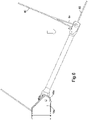
- FIG 4 there is shown a side view of the mooring system of Figure 3a .
- Figure 4 where compared with Figure 3a , shows that, in use, a reduction in the pulling force on the second portion 35' of the line 35, 35', the pulling force being in a direction away from the guide 25a, the connection member 20a moves towards the seat 40a.
- the tension of the mooring line 60 is substantially taken by a support line 80.
- the proximal end 56a of the connection member 20a can be lowered from the position shown in Figure 3a , to the position shown in Figure 4 , and subsequently to the position shown in Figures 5a and 5b .
- connection member 20a has moved into the pair of seats 40a, 40b.
- the connection member 20a can move towards the pair of seats 40a, 40b at least partly under the force of gravity and/or under a force induced by a tension, such as a mooring tension in the mooring line.
- the connection member 20a moves towards the pair of seats 40a, 40b, from the position shown in Figure 3a to the position shown in Figure 5a , along the guide portion 65.
- the apparatus 10a; 10b; 10c; 10d can optionally comprise a retaining pin 95.
- the retaining pin 95 is adapted to restrict movement of the connection member 20a when the connection member 20a is positioned on the pair of seats 40a, 40b.
- FIG. 6 there is shown a side view of the mooring system 50 of Figure 3a , with the connection member 20a in a lowered position.
- Figure 6 shows an alternative method of installation to that of Figures 4 and 5a .
- the support line 80 has been lowered.
- the connection member 20a is substantially oriented in line with a straight portion of the guide portion 65.
- Figure 7 shows a subsequent position of the connection member 20a relative to the socket 15a following a reduction in the pulling force on the second portion 35' of the line 35, 35'.
- the connection member 20a is in a retained position.
- connection member 20a In order to remove a connection member 20a from a socket 15a, the installation process is essentially reversed. That is, a pulling force is applied to the second portion 35' of line 35, 35'. The pulling force pulls the connection member 20a towards and/or out of the socket 15a and/or along the guide portion 65 and/or away from the guide portion 65. Next, a reduction in the pulling force on a second portion 35' of the line, the pulling force being in a direction away from the guide 25a, coupled with a further pulling force applied to the connection member 20a, moves the connection member 20a out ot the socket 15a and/or in a direction away from the socket 15a. The further pulling force is applied to the support line 80.
- the support line 80 comprises a bridle 85 to maintain the orientation of the connection member 20a during installation and/or removal.
- Figure 8 shows a perspective view of a mooring system 50, according to the first embodiment of the present invention.
- the connection member 20a has been lowered to a mooring angle. That is, the connection member 20a is aligned with the mooring line 60, such that a mooring tension is taken by the socket 15a, and in particular by the pair of seats 40a, 40b.
- Figure 9 shows a final stage in the installation process, wherein the support line 80 is removed.
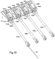
- FIG 10 shows a perspective view of a mooring system, according to another embodiment of the present invention.
- Each connection member 120a; 120b; 120c; 120d comprises a retaining member 130a; 130b; 130c; 130d.
- Each retaining member 130a; 130b; 130c; 130d comprises a pair of shoulders or wings 140a; 140b; 140c; 140d.
- the pair of shoulders or wings 140a; 140b; 140c; 140d is adapted to move around and/or rotate around or about an outer surface of each pair of seats 150a; 150b; 150c; 150d.
- Each connection member 120a; 120b; 120c; 120d is adapted to be located in a retained position by each pair of shoulders or wings 140a; 140b; 140c; 140d. In the retained position, each pair of seats 150a; 150b; 150c; 150d is located between each pair of trunnions 90a, 90b and each pair of shoulders or wings 140a; 140b; 140c; 140d.
- FIG. 11 there is shown a further embodiment of a mooring apparatus, generally denoted 300.
- the mooring apparatus 300 comprises the same socket 15a as the socket of the embodiment shown in Figure 1 .
- the mooring apparatus 300 comprises a connection member 320a.
- the connection member 320a is receivable within socket 15a.
- the connection member 320a comprises a tensioner apparatus 330.
- the tensioner apparatus 330 comprises a frame 335 and a guide portion 340 for guiding a portion of a chain 345.
- the guide portion 340 is a chain wheel.
- the tensioner apparatus 330 comprises a locking means 350.
- the locking means 350 is a chain stopper.
- the guide portion 340 is moveably connected to the frame 335.
- the locking means 350 is pivotably connected to the frame 335.
- tne locking means 350 restrains the guide portion 340 and/or the chain 345.
- the locking means 350 can be adapted to be locked in a disengaged position wherein the locking means 350 does not restrain the guide portion 340 and/or the chain 345.
- the tensioner apparatus 300 comprises a hole 355.
- a locking pin 360 can be inserted in the hole 355, such that the locking pin 360 engages with the locking means 350, thus retaining the locking means 350 in the disengaged position.
- the apparatus comprises a universal joint. That is, the apparatus shown is a "Dual Axis" device.
- the connection member 20a is rotatable on the pair of trunnions 90a, 90b, about a first axis defined by the trunnions 90a, 90b.
- the connection member 20a is also rotatable about a second axis, the second axis being substantially perpendicular to the first axis, the second axis being centred on joint 160a.
- the connection member may be a "Single Axis" device, and may not comprise joint 160a. Such an arrangement would, for example, be adapted for use on a structure, wherein the structure has a rotatable portion, such as a turret mooring.
- the method described herein may permit the mooring line to be pre-cut to size and installed without a tensioning device on such, since the mooring line can be pulled in at a tension above the nominal/design tension of the mooring line to a "pulled in” position and then lowered down to the seat to achieve a design tension.
Landscapes
- Chemical & Material Sciences (AREA)
- Engineering & Computer Science (AREA)
- Combustion & Propulsion (AREA)
- Mechanical Engineering (AREA)
- Ocean & Marine Engineering (AREA)
- Hooks, Suction Cups, And Attachment By Adhesive Means (AREA)
- Other Liquid Machine Or Engine Such As Wave Power Use (AREA)
- Bridges Or Land Bridges (AREA)
Claims (5)
- Verfahren zum Konfigurieren einer Festmachvorrichtung (10a, 10b, 10c, 10d), wobei das Verfahren Folgendes umfasst:
Bereitstellen einer Festmachvorrichtung, umfassend:einen Sockel, welcher ein Paar von Sitzen umfasst,ein Verbindungsglied, welches ein Paar von Zapfen umfasst, welche derart angeordnet sind, dass das Verbindungsglied um eine Achse drehbar ist, welche durch das Paar von Zapfen definiert ist, wenn das Verbindungsglied in dem Sockel aufgenommen ist, undeine Positionierungsanordnung, umfassend eine Führung und konfigurierbar, um das Paar von Zapfen auf dem Paar von Sitzen durch eine Leine, welche mit dem Verbindungsglied verbunden ist und sich um die Führung erstreckt, anzuordnen,wobei das Verfahren ferner Folgendes umfasst:Verbinden eines ersten Abschnitts einer Leine (35) mit einer Leineneingriffsvorrichtung (30a), welche an einem proximalen Abschnitt des Verbindungsglieds angeordnet ist und Legen der Leine um die Führung; undAnordnen des Paars von Zapfen auf dem Paar von Sitzen während ein distaler Abschnitt des Verbindungsglieds mit einer Festmachleine verbunden ist, indem eine Ziehkraft ausgeübt wird, wonach die auf die Leine ausgeübte Ziehkraft in einer Richtung weg von der Führung reduziert wird. - Verfahren nach Anspruch 1, wobei die Festmachvorrichtung mit einem Paar von Schultern oder Flügeln versehen ist, welche angepasst sind, um sich um eine Außenfläche des Sitzes zu bewegen und/oder um sich rund um diese Außenfläche zu drehen, und wobei das Verfahren Folgendes umfasst:
Positionieren des Verbindungsglieds in einer Festhalteposition innerhalb jedes Sockels durch Positionieren jedes Sitzes zwischen einem des Paars von Zapfen und einer der Schultern oder Flügel. - Verfahren nach Anspruch 1 oder 2, wobei das Paar von Sitzen der Festmachvorrichtung offene Sitze sind.
- Verfahren nach einem der vorhergehenden Ansprüche, wobei das Paar von Sitzen (40a, 40b) oder ein Basisaufnahmeabschnitt oder ein Gewichtstragabschnitt jedes Sitzes des Paars von Sitzen mindestens teilweise oder im Wesentlichen einer Führung zugewandt oder in der Richtung dieser gerichtet ist.
- Verfahren nach einem der vorhergehenden Ansprüche, wobei mindestens ein Abschnitt jedes Sitzes des Paars von Sitzen im Wesentlichen eine U-Form, eine Hakenform oder eine J-Form aufweist.
Priority Applications (1)
| Application Number | Priority Date | Filing Date | Title |
|---|---|---|---|
| EP22168584.5A EP4053008A1 (de) | 2017-04-27 | 2018-04-26 | Festmachvorrichtung |
Applications Claiming Priority (3)
| Application Number | Priority Date | Filing Date | Title |
|---|---|---|---|
| GBGB1706745.5A GB201706745D0 (en) | 2017-04-27 | 2017-04-27 | Mooring apparatus |
| GBGB1711907.4A GB201711907D0 (en) | 2017-04-27 | 2017-07-24 | Mooring apparatus |
| PCT/GB2018/051102 WO2018197881A1 (en) | 2017-04-27 | 2018-04-26 | Mooring apparatus |
Related Child Applications (1)
| Application Number | Title | Priority Date | Filing Date |
|---|---|---|---|
| EP22168584.5A Division EP4053008A1 (de) | 2017-04-27 | 2018-04-26 | Festmachvorrichtung |
Publications (2)
| Publication Number | Publication Date |
|---|---|
| EP3615412A1 EP3615412A1 (de) | 2020-03-04 |
| EP3615412B1 true EP3615412B1 (de) | 2022-04-20 |
Family
ID=59011056
Family Applications (2)
| Application Number | Title | Priority Date | Filing Date |
|---|---|---|---|
| EP18728692.7A Active EP3615412B1 (de) | 2017-04-27 | 2018-04-26 | Festmachvorrichtung |
| EP22168584.5A Pending EP4053008A1 (de) | 2017-04-27 | 2018-04-26 | Festmachvorrichtung |
Family Applications After (1)
| Application Number | Title | Priority Date | Filing Date |
|---|---|---|---|
| EP22168584.5A Pending EP4053008A1 (de) | 2017-04-27 | 2018-04-26 | Festmachvorrichtung |
Country Status (7)
| Country | Link |
|---|---|
| US (1) | US11254392B2 (de) |
| EP (2) | EP3615412B1 (de) |
| DK (1) | DK3615412T3 (de) |
| ES (1) | ES2923023T3 (de) |
| GB (2) | GB201706745D0 (de) |
| PT (1) | PT3615412T (de) |
| WO (1) | WO2018197881A1 (de) |
Families Citing this family (3)
| Publication number | Priority date | Publication date | Assignee | Title |
|---|---|---|---|---|
| EP3490880B1 (de) | 2016-08-01 | 2025-12-10 | Flintstone Technology Limited | Vertäuungsspanner und verfahren dafür |
| NO343647B1 (en) * | 2017-10-16 | 2019-04-23 | Apl Tech As | System and method for connecting a mooring line to a body |
| GB2624178A (en) * | 2022-11-08 | 2024-05-15 | Flintstone Tech Limited | Support apparatus for a mooring device |
Citations (1)
| Publication number | Priority date | Publication date | Assignee | Title |
|---|---|---|---|---|
| US5364075A (en) * | 1992-09-03 | 1994-11-15 | Smith Berger Marine, Inc. | Retractable mount for a mooring line guide and process for operating the same |
Family Cites Families (7)
| Publication number | Priority date | Publication date | Assignee | Title |
|---|---|---|---|---|
| US4193368A (en) | 1978-01-20 | 1980-03-18 | Chicago Bridge & Iron Company | Offshore mooring system for vessel or ship |
| CA2069205A1 (en) * | 1992-05-22 | 1993-11-23 | Nelson John Whitehead | Collapsible member |
| JP5591795B2 (ja) * | 2008-05-19 | 2014-09-17 | シングル・ブイ・ムーリングス・インコーポレイテッド | おもりが付けられたライザ支持ブイを備えた分離可能な係留システム |
| WO2013186553A1 (en) * | 2012-06-11 | 2013-12-19 | Ftl Subsea Ltd. | Subsea connector |
| GB2512312B (en) * | 2013-03-25 | 2015-04-29 | Ftl Subsea Ltd | Subsea connector comprising male and female portions |
| GB2527782B (en) * | 2014-07-01 | 2017-01-18 | Flintstone Tech Ltd | A connector having an inductive transmission |
| WO2016118006A1 (en) | 2015-01-20 | 2016-07-28 | Sbm Schiedam B.V. | Spread moored chain connector and floating structure comprising such a chain connector |
-
2017
- 2017-04-27 GB GBGB1706745.5A patent/GB201706745D0/en not_active Ceased
- 2017-07-24 GB GBGB1711907.4A patent/GB201711907D0/en not_active Ceased
-
2018
- 2018-04-26 DK DK18728692.7T patent/DK3615412T3/da active
- 2018-04-26 PT PT187286927T patent/PT3615412T/pt unknown
- 2018-04-26 US US16/606,746 patent/US11254392B2/en active Active
- 2018-04-26 WO PCT/GB2018/051102 patent/WO2018197881A1/en not_active Ceased
- 2018-04-26 EP EP18728692.7A patent/EP3615412B1/de active Active
- 2018-04-26 EP EP22168584.5A patent/EP4053008A1/de active Pending
- 2018-04-26 ES ES18728692T patent/ES2923023T3/es active Active
Patent Citations (1)
| Publication number | Priority date | Publication date | Assignee | Title |
|---|---|---|---|---|
| US5364075A (en) * | 1992-09-03 | 1994-11-15 | Smith Berger Marine, Inc. | Retractable mount for a mooring line guide and process for operating the same |
Also Published As
| Publication number | Publication date |
|---|---|
| PT3615412T (pt) | 2022-05-30 |
| EP3615412A1 (de) | 2020-03-04 |
| US20200094923A1 (en) | 2020-03-26 |
| EP4053008A1 (de) | 2022-09-07 |
| GB201706745D0 (en) | 2017-06-14 |
| US11254392B2 (en) | 2022-02-22 |
| WO2018197881A1 (en) | 2018-11-01 |
| ES2923023T3 (es) | 2022-09-22 |
| GB201711907D0 (en) | 2017-09-06 |
| DK3615412T3 (da) | 2022-06-27 |
Similar Documents
| Publication | Publication Date | Title |
|---|---|---|
| EP2729353B1 (de) | Spannverfahren für ankertau | |
| US10577056B2 (en) | Mooring pulley tensioning system | |
| AU2018437072B2 (en) | Mooring and tensioning methods, systems, and apparatus | |
| EP3251942B1 (de) | Vertäuungsriemenscheibenspannsystem | |
| US11220314B2 (en) | System and method for connecting a mooring line to a body | |
| EP3490880B1 (de) | Vertäuungsspanner und verfahren dafür | |
| EP3615412B1 (de) | Festmachvorrichtung | |
| EP3615413B1 (de) | Festmachvorrichtung | |
| KR20150020179A (ko) | 인라인 기계식 분리 장치 | |
| EP2148807B1 (de) | Verfahren und vorrichtungen zum festmachen und verbinden von leinen an gegenständen auf dem meeresboden | |
| WO2018217085A1 (en) | Deployment method to deploy a cable from a vessel | |
| GB2555503A (en) | Mooring method |
Legal Events
| Date | Code | Title | Description |
|---|---|---|---|
| STAA | Information on the status of an ep patent application or granted ep patent |
Free format text: STATUS: UNKNOWN |
|
| STAA | Information on the status of an ep patent application or granted ep patent |
Free format text: STATUS: THE INTERNATIONAL PUBLICATION HAS BEEN MADE |
|
| PUAI | Public reference made under article 153(3) epc to a published international application that has entered the european phase |
Free format text: ORIGINAL CODE: 0009012 |
|
| STAA | Information on the status of an ep patent application or granted ep patent |
Free format text: STATUS: REQUEST FOR EXAMINATION WAS MADE |
|
| 17P | Request for examination filed |
Effective date: 20191016 |
|
| AK | Designated contracting states |
Kind code of ref document: A1 Designated state(s): AL AT BE BG CH CY CZ DE DK EE ES FI FR GB GR HR HU IE IS IT LI LT LU LV MC MK MT NL NO PL PT RO RS SE SI SK SM TR |
|
| AX | Request for extension of the european patent |
Extension state: BA ME |
|
| DAV | Request for validation of the european patent (deleted) | ||
| DAX | Request for extension of the european patent (deleted) | ||
| STAA | Information on the status of an ep patent application or granted ep patent |
Free format text: STATUS: EXAMINATION IS IN PROGRESS |
|
| 17Q | First examination report despatched |
Effective date: 20210324 |
|
| GRAP | Despatch of communication of intention to grant a patent |
Free format text: ORIGINAL CODE: EPIDOSNIGR1 |
|
| STAA | Information on the status of an ep patent application or granted ep patent |
Free format text: STATUS: GRANT OF PATENT IS INTENDED |
|
| INTG | Intention to grant announced |
Effective date: 20211108 |
|
| GRAS | Grant fee paid |
Free format text: ORIGINAL CODE: EPIDOSNIGR3 |
|
| GRAA | (expected) grant |
Free format text: ORIGINAL CODE: 0009210 |
|
| STAA | Information on the status of an ep patent application or granted ep patent |
Free format text: STATUS: THE PATENT HAS BEEN GRANTED |
|
| AK | Designated contracting states |
Kind code of ref document: B1 Designated state(s): AL AT BE BG CH CY CZ DE DK EE ES FI FR GB GR HR HU IE IS IT LI LT LU LV MC MK MT NL NO PL PT RO RS SE SI SK SM TR |
|
| REG | Reference to a national code |
Ref country code: GB Ref legal event code: FG4D |
|
| REG | Reference to a national code |
Ref country code: CH Ref legal event code: EP |
|
| REG | Reference to a national code |
Ref country code: IE Ref legal event code: FG4D |
|
| REG | Reference to a national code |
Ref country code: DE Ref legal event code: R096 Ref document number: 602018034141 Country of ref document: DE |
|
| REG | Reference to a national code |
Ref country code: AT Ref legal event code: REF Ref document number: 1484982 Country of ref document: AT Kind code of ref document: T Effective date: 20220515 |
|
| REG | Reference to a national code |
Ref country code: PT Ref legal event code: SC4A Ref document number: 3615412 Country of ref document: PT Date of ref document: 20220530 Kind code of ref document: T Free format text: AVAILABILITY OF NATIONAL TRANSLATION Effective date: 20220524 |
|
| REG | Reference to a national code |
Ref country code: DK Ref legal event code: T3 Effective date: 20220622 |
|
| REG | Reference to a national code |
Ref country code: NL Ref legal event code: FP |
|
| REG | Reference to a national code |
Ref country code: SE Ref legal event code: TRGR |
|
| PGFP | Annual fee paid to national office [announced via postgrant information from national office to epo] |
Ref country code: DK Payment date: 20220525 Year of fee payment: 5 |
|
| REG | Reference to a national code |
Ref country code: NO Ref legal event code: T2 Effective date: 20220420 |
|
| REG | Reference to a national code |
Ref country code: LT Ref legal event code: MG9D |
|
| REG | Reference to a national code |
Ref country code: AT Ref legal event code: MK05 Ref document number: 1484982 Country of ref document: AT Kind code of ref document: T Effective date: 20220420 |
|
| REG | Reference to a national code |
Ref country code: ES Ref legal event code: FG2A Ref document number: 2923023 Country of ref document: ES Kind code of ref document: T3 Effective date: 20220922 |
|
| PG25 | Lapsed in a contracting state [announced via postgrant information from national office to epo] |
Ref country code: LT Free format text: LAPSE BECAUSE OF FAILURE TO SUBMIT A TRANSLATION OF THE DESCRIPTION OR TO PAY THE FEE WITHIN THE PRESCRIBED TIME-LIMIT Effective date: 20220420 Ref country code: HR Free format text: LAPSE BECAUSE OF FAILURE TO SUBMIT A TRANSLATION OF THE DESCRIPTION OR TO PAY THE FEE WITHIN THE PRESCRIBED TIME-LIMIT Effective date: 20220420 Ref country code: GR Free format text: LAPSE BECAUSE OF FAILURE TO SUBMIT A TRANSLATION OF THE DESCRIPTION OR TO PAY THE FEE WITHIN THE PRESCRIBED TIME-LIMIT Effective date: 20220721 Ref country code: FI Free format text: LAPSE BECAUSE OF FAILURE TO SUBMIT A TRANSLATION OF THE DESCRIPTION OR TO PAY THE FEE WITHIN THE PRESCRIBED TIME-LIMIT Effective date: 20220420 Ref country code: BG Free format text: LAPSE BECAUSE OF FAILURE TO SUBMIT A TRANSLATION OF THE DESCRIPTION OR TO PAY THE FEE WITHIN THE PRESCRIBED TIME-LIMIT Effective date: 20220720 Ref country code: AT Free format text: LAPSE BECAUSE OF FAILURE TO SUBMIT A TRANSLATION OF THE DESCRIPTION OR TO PAY THE FEE WITHIN THE PRESCRIBED TIME-LIMIT Effective date: 20220420 |
|
| PG25 | Lapsed in a contracting state [announced via postgrant information from national office to epo] |
Ref country code: RS Free format text: LAPSE BECAUSE OF FAILURE TO SUBMIT A TRANSLATION OF THE DESCRIPTION OR TO PAY THE FEE WITHIN THE PRESCRIBED TIME-LIMIT Effective date: 20220420 Ref country code: PL Free format text: LAPSE BECAUSE OF FAILURE TO SUBMIT A TRANSLATION OF THE DESCRIPTION OR TO PAY THE FEE WITHIN THE PRESCRIBED TIME-LIMIT Effective date: 20220420 Ref country code: LV Free format text: LAPSE BECAUSE OF FAILURE TO SUBMIT A TRANSLATION OF THE DESCRIPTION OR TO PAY THE FEE WITHIN THE PRESCRIBED TIME-LIMIT Effective date: 20220420 Ref country code: IS Free format text: LAPSE BECAUSE OF FAILURE TO SUBMIT A TRANSLATION OF THE DESCRIPTION OR TO PAY THE FEE WITHIN THE PRESCRIBED TIME-LIMIT Effective date: 20220820 |
|
| REG | Reference to a national code |
Ref country code: CH Ref legal event code: PL |
|
| REG | Reference to a national code |
Ref country code: BE Ref legal event code: MM Effective date: 20220430 |
|
| REG | Reference to a national code |
Ref country code: DE Ref legal event code: R097 Ref document number: 602018034141 Country of ref document: DE |
|
| PG25 | Lapsed in a contracting state [announced via postgrant information from national office to epo] |
Ref country code: SM Free format text: LAPSE BECAUSE OF FAILURE TO SUBMIT A TRANSLATION OF THE DESCRIPTION OR TO PAY THE FEE WITHIN THE PRESCRIBED TIME-LIMIT Effective date: 20220420 Ref country code: SK Free format text: LAPSE BECAUSE OF FAILURE TO SUBMIT A TRANSLATION OF THE DESCRIPTION OR TO PAY THE FEE WITHIN THE PRESCRIBED TIME-LIMIT Effective date: 20220420 Ref country code: RO Free format text: LAPSE BECAUSE OF FAILURE TO SUBMIT A TRANSLATION OF THE DESCRIPTION OR TO PAY THE FEE WITHIN THE PRESCRIBED TIME-LIMIT Effective date: 20220420 Ref country code: MC Free format text: LAPSE BECAUSE OF FAILURE TO SUBMIT A TRANSLATION OF THE DESCRIPTION OR TO PAY THE FEE WITHIN THE PRESCRIBED TIME-LIMIT Effective date: 20220420 Ref country code: LU Free format text: LAPSE BECAUSE OF NON-PAYMENT OF DUE FEES Effective date: 20220426 Ref country code: LI Free format text: LAPSE BECAUSE OF NON-PAYMENT OF DUE FEES Effective date: 20220430 Ref country code: EE Free format text: LAPSE BECAUSE OF FAILURE TO SUBMIT A TRANSLATION OF THE DESCRIPTION OR TO PAY THE FEE WITHIN THE PRESCRIBED TIME-LIMIT Effective date: 20220420 Ref country code: CZ Free format text: LAPSE BECAUSE OF FAILURE TO SUBMIT A TRANSLATION OF THE DESCRIPTION OR TO PAY THE FEE WITHIN THE PRESCRIBED TIME-LIMIT Effective date: 20220420 Ref country code: CH Free format text: LAPSE BECAUSE OF NON-PAYMENT OF DUE FEES Effective date: 20220430 |
|
| PLBE | No opposition filed within time limit |
Free format text: ORIGINAL CODE: 0009261 |
|
| STAA | Information on the status of an ep patent application or granted ep patent |
Free format text: STATUS: NO OPPOSITION FILED WITHIN TIME LIMIT |
|
| PG25 | Lapsed in a contracting state [announced via postgrant information from national office to epo] |
Ref country code: BE Free format text: LAPSE BECAUSE OF NON-PAYMENT OF DUE FEES Effective date: 20220430 |
|
| 26N | No opposition filed |
Effective date: 20230123 |
|
| PG25 | Lapsed in a contracting state [announced via postgrant information from national office to epo] |
Ref country code: AL Free format text: LAPSE BECAUSE OF FAILURE TO SUBMIT A TRANSLATION OF THE DESCRIPTION OR TO PAY THE FEE WITHIN THE PRESCRIBED TIME-LIMIT Effective date: 20220420 |
|
| PG25 | Lapsed in a contracting state [announced via postgrant information from national office to epo] |
Ref country code: IE Free format text: LAPSE BECAUSE OF NON-PAYMENT OF DUE FEES Effective date: 20220426 |
|
| PG25 | Lapsed in a contracting state [announced via postgrant information from national office to epo] |
Ref country code: SI Free format text: LAPSE BECAUSE OF FAILURE TO SUBMIT A TRANSLATION OF THE DESCRIPTION OR TO PAY THE FEE WITHIN THE PRESCRIBED TIME-LIMIT Effective date: 20220420 |
|
| REG | Reference to a national code |
Ref country code: DK Ref legal event code: EBP Effective date: 20230430 |
|
| PG25 | Lapsed in a contracting state [announced via postgrant information from national office to epo] |
Ref country code: MK Free format text: LAPSE BECAUSE OF FAILURE TO SUBMIT A TRANSLATION OF THE DESCRIPTION OR TO PAY THE FEE WITHIN THE PRESCRIBED TIME-LIMIT Effective date: 20220420 Ref country code: DK Free format text: LAPSE BECAUSE OF NON-PAYMENT OF DUE FEES Effective date: 20230430 Ref country code: CY Free format text: LAPSE BECAUSE OF FAILURE TO SUBMIT A TRANSLATION OF THE DESCRIPTION OR TO PAY THE FEE WITHIN THE PRESCRIBED TIME-LIMIT Effective date: 20220420 |
|
| PG25 | Lapsed in a contracting state [announced via postgrant information from national office to epo] |
Ref country code: HU Free format text: LAPSE BECAUSE OF FAILURE TO SUBMIT A TRANSLATION OF THE DESCRIPTION OR TO PAY THE FEE WITHIN THE PRESCRIBED TIME-LIMIT; INVALID AB INITIO Effective date: 20180426 |
|
| PG25 | Lapsed in a contracting state [announced via postgrant information from national office to epo] |
Ref country code: TR Free format text: LAPSE BECAUSE OF FAILURE TO SUBMIT A TRANSLATION OF THE DESCRIPTION OR TO PAY THE FEE WITHIN THE PRESCRIBED TIME-LIMIT Effective date: 20220420 |
|
| PG25 | Lapsed in a contracting state [announced via postgrant information from national office to epo] |
Ref country code: MT Free format text: LAPSE BECAUSE OF FAILURE TO SUBMIT A TRANSLATION OF THE DESCRIPTION OR TO PAY THE FEE WITHIN THE PRESCRIBED TIME-LIMIT Effective date: 20220420 |
|
| PG25 | Lapsed in a contracting state [announced via postgrant information from national office to epo] |
Ref country code: BG Free format text: LAPSE BECAUSE OF FAILURE TO SUBMIT A TRANSLATION OF THE DESCRIPTION OR TO PAY THE FEE WITHIN THE PRESCRIBED TIME-LIMIT Effective date: 20220420 |
|
| PG25 | Lapsed in a contracting state [announced via postgrant information from national office to epo] |
Ref country code: BG Free format text: LAPSE BECAUSE OF FAILURE TO SUBMIT A TRANSLATION OF THE DESCRIPTION OR TO PAY THE FEE WITHIN THE PRESCRIBED TIME-LIMIT Effective date: 20220420 |
|
| PGFP | Annual fee paid to national office [announced via postgrant information from national office to epo] |
Ref country code: NL Payment date: 20250418 Year of fee payment: 8 |
|
| PGFP | Annual fee paid to national office [announced via postgrant information from national office to epo] |
Ref country code: DE Payment date: 20250422 Year of fee payment: 8 |
|
| PGFP | Annual fee paid to national office [announced via postgrant information from national office to epo] |
Ref country code: ES Payment date: 20250530 Year of fee payment: 8 Ref country code: GB Payment date: 20250423 Year of fee payment: 8 |
|
| PGFP | Annual fee paid to national office [announced via postgrant information from national office to epo] |
Ref country code: NO Payment date: 20250424 Year of fee payment: 8 |
|
| PGFP | Annual fee paid to national office [announced via postgrant information from national office to epo] |
Ref country code: IT Payment date: 20250424 Year of fee payment: 8 |
|
| PGFP | Annual fee paid to national office [announced via postgrant information from national office to epo] |
Ref country code: PT Payment date: 20250417 Year of fee payment: 8 |
|
| PGFP | Annual fee paid to national office [announced via postgrant information from national office to epo] |
Ref country code: FR Payment date: 20250425 Year of fee payment: 8 |
|
| PGFP | Annual fee paid to national office [announced via postgrant information from national office to epo] |
Ref country code: SE Payment date: 20250429 Year of fee payment: 8 |