EP3615708B9 - Verfahren zur herstellung eines halbleiter- oder leiter-materials und dessen verwendung - Google Patents
Verfahren zur herstellung eines halbleiter- oder leiter-materials und dessen verwendung Download PDFInfo
- Publication number
- EP3615708B9 EP3615708B9 EP18725111.1A EP18725111A EP3615708B9 EP 3615708 B9 EP3615708 B9 EP 3615708B9 EP 18725111 A EP18725111 A EP 18725111A EP 3615708 B9 EP3615708 B9 EP 3615708B9
- Authority
- EP
- European Patent Office
- Prior art keywords
- graphene
- electrode
- conductor
- electrodes
- semiconductor
- Prior art date
- Legal status (The legal status is an assumption and is not a legal conclusion. Google has not performed a legal analysis and makes no representation as to the accuracy of the status listed.)
- Active
Links
Images



Classifications
-
- C—CHEMISTRY; METALLURGY
- C01—INORGANIC CHEMISTRY
- C01B—NON-METALLIC ELEMENTS; COMPOUNDS THEREOF; METALLOIDS OR COMPOUNDS THEREOF NOT COVERED BY SUBCLASS C01C
- C01B32/00—Carbon; Compounds thereof
- C01B32/15—Nano-sized carbon materials
- C01B32/182—Graphene
- C01B32/184—Preparation
- C01B32/19—Preparation by exfoliation
-
- C—CHEMISTRY; METALLURGY
- C25—ELECTROLYTIC OR ELECTROPHORETIC PROCESSES; APPARATUS THEREFOR
- C25B—ELECTROLYTIC OR ELECTROPHORETIC PROCESSES FOR THE PRODUCTION OF COMPOUNDS OR NON-METALS; APPARATUS THEREFOR
- C25B1/00—Electrolytic production of inorganic compounds or non-metals
- C25B1/01—Products
Definitions
- the invention relates to a method for producing a semiconductor or conductor material from monolayers or with a layered structure by electrolytic exfoliation and its use.
- graphene is a monolayer, i.e. a single layer of graphite, only one atomic layer thick, a naturally occurring form of carbon in its pure form.
- Graphene also refers to material in which some of these monolayers are stacked on top of one another.
- Graphene can be understood as a two-dimensional network of chained benzene rings, which among other things has enormous electrical conductivity. Due to its electronic, thermal, optical and mechanical properties, its use in many areas of technology is of great interest. Processes for the scalable and efficient production of high quality conductor and semiconductor materials, if possible processable from the solution, such as graphene, are therefore the subject of intensive research work.
- the electrochemical exfoliation of semiconductor or conductor materials from two-dimensionally structured or layered base materials, such as graphite, is a cost-effective and very efficient way of splitting off individual layers.
- the two-dimensionally structured base material can either be used as an anode in aqueous solutions of ionic liquids (see for example X. Wang, PF Fulvio, GA Baker, GM Veith, RR Unocic, SM Mahurin, M. Chi, S. Dai, Chem. Commun. 2010, 46, 4487-4489 ) or mineral acids (see for example a) KS Rao, J. Sentilnathan, H.-W. Cho, J.-J. Wu, M. Yoshimura, Adv. Funct. Mater. 2015, 25,298-305 ; b) K. Parvez, R. Li, SR Puniredd, Y. Hernandez, F. Hinkel, S. Wang, X.
- the base material as a cathode, e.g. in organic solvents containing lithium salts ( Z. Zeng, Z. Yin, X. Huang, H. Li, Q. He, G. Lu, F. Boey, H. Zhang, Angew. Chem. Int. Ed. 2011, 50, 11093-11097 ) or quaternary ammonium salts ( AJ Cooper, NR Wilson, IA Kinloch, RAW Dryfe, Carbon 2014, 66, 340-350 ).
- An electrically negative alignment of the cathode attracts the positively charged ions of the electrolyte, which in turn penetrate between the individual layers of the base material and facilitate their separation.
- the anodic exfoliation achieves good production rates (over 10 g / h), thin-layer graphene flakes from 1 to 3 monolayers of graphene in high yields of up to 70%.
- the average width of the flakes is also relatively high at up to 5 ⁇ m.
- the disadvantage of the graphene produced in this way is that it contains high proportions of oxygen groups. This is due to oxygen radicals such as HO or O, which are formed during the manufacturing process by splitting water and adding to the graphene layers (see KS Rao, J. Sentilnathan, H.-W. Cho, J.-J. Wu, M. Yoshimura, Adv. Funct. Mater. 2015, 25, 298-305 ).
- Cathodic exfoliation enables the production of pure graphene, but disadvantageously with very high layer thicknesses of at least 5 layers and relatively low production rates of 0.5 to 2 g per hour ( AM Abdelkader, IA Kinloch, RAW Dryfe, ACSAppl. Mater. Interfaces 2014, 6, 1632-1639 ).
- EP 2878709 A1 describes a method for producing two-dimensional structured carbon materials by electrochemical exfoliation, at least one of the electrodes comprising a carbon-containing base material with a layer structure and graphene being split off from this electrode by applying a voltage by means of direct current.
- the electrolyte solution used contains an ammonium cation and an inorganic sulfur-containing anion.
- the ammonium cation can have 4 alkyl radicals on the nitrogen.
- the polarity of the electrodes can be reversed during electrolysis.
- a low voltage of +2.5 V is applied to the graphite electrodes in order to moisten the surface of the electrode and to force the anions to penetrate between the graphite layers.
- the disadvantage here is that the graphite is also oxidized to a high degree.
- the electrolysis is operated by means of direct current, which can change direction periodically. If the electrode is connected as a cathode, the graphene oxide is reduced. The polarity of the electrodes is reversed with a period of 2 s to 1 minute.Disadvantageously, the yield of exfoliated graphene is only 5 to 8 m% of the graphite used.
- the object of the invention is to provide a cost-effective, efficient and scalable method for producing conductor and / or semiconductor materials, in particular graphene, from two-dimensionally structured, layered base materials by means of exfoliation.
- the object is achieved by a method for producing a semiconductor or conductor material from a two-dimensionally layered structured base material by electrolytic exfoliation in an electrolytic cell comprising at least one pair of electrodes from a first and a second electrode, and an electrolyte solution containing at least one dissolved tetraalkylammonium salt or at least one dissolved tetraalkylammonium salt and sulfuric acid wherein the anion of the tetraalkylammonium salt is selected from sulfate, hydrogen sulfate, thiosulfate, sulfite, nitrate or hydroxide, Both electrodes of the electrode pair contain the two-dimensionally layered structured base material, and the polarity of the first and second electrodes is periodically reversed during the electrolysis, the polarity of the electrodes being reversed by applying an alternating voltage and the reversal frequency of the alternating voltage preferably 0.001 to 10 Hz is.
- a conductor or semiconductor material is an electrically conductive material with a highly ordered, layered structure, consisting of a monolayer of the material or of several layers of the material arranged one above the other.
- the semiconductor material has a specific band gap, which is formed from the energy difference between the valence band and the conduction band.
- the two-dimensionally layered structured base material is selected from graphite, carbon-based semiconductor or conductor polymers in the form of two-dimensionally structured base material and / or layered chalcogenides.
- Graphite can be naturally occurring or synthetically produced graphite.
- the exfoliation of the semiconductor or conductor material from or from the two-dimensional, layered structured base material takes place electrolytically in an electrolysis cell which contains at least one pair of electrodes.
- a pair of electrodes comprises a first electrode E1 and a second electrode E2. Both electrodes of the electrode pair contain the base material.
- At least one electrode contains the base material in the form of flakes, powder, fibers, foils, pieces, pastes or a mixture of these.
- the electrode can also be a single flake of the base material, or several of these flakes which are either pressed against one another or connected to one another by a conductive material.
- the electrolyte solution of the electrolytic cell is an aqueous solution.
- the electrolyte solution contains at least one polar organic solvent, for example propylene carbonate or acetonitrile.
- the at least one pair of electrodes is introduced into the electrolyte solution and the electrolysis is operated in such a way that the polarity of the first and the second electrode is periodically reversed.
- the polarity is reversed by applying an alternating voltage between the first and the second electrode.
- the function of each electrode changes periodically between anode and cathode.
- the voltage at which the electrolysis is operated is +/- 2 V to +/- 20 V, preferably +/- 5V to +/- 15 V, particularly preferably +/- 10 V.
- Both electrodes of the electrode pair contain the two-dimensionally layered structured base material.
- oxygen-containing radicals such as HO or O are initially formed in the anode area, which attack and add to the interfaces or intrinsic defects of the base material, forming oxides of the base material.
- the outer layers of the base material are driven apart so that the anions of the electrolyte can slide far in between and expand the distance between the individual layers of the base material.
- the anions are reduced, whereby a gas is formed that drives the individual layers of the base material apart even further.
- the oxygen functionalities at the electrode which is now connected as a cathode, so that the base material is created again from the oxides of the base material and oxygen defects are removed.
- the intercalation of the cations of the electrolyte also takes place and leads to the widening of the distance between the layers to the extent that the intermolecular forces can be overcome, so that individual layers split off from the electrode. A monolayer or a thin layer of the base material is thus exfoliated from the electrode.
- both electrodes of the electrode pair contain the two-dimensionally layered structured base material, the exfoliation takes place simultaneously on both electrodes E1 and E2.
- the layers are split off at E1; if the polarity is reversed again, again at E2.
- the application according to the invention of an alternating current / an alternating voltage between the two electrodes can advantageously produce simultaneous exfoliation at both electrodes and high yields of exfoliated material, that is to say of semiconductor or conductor material.
- Another advantage of this embodiment is that no expensive noble metal counter-electrodes, such as those from Su et al. used ( Su CY, Lu AY, Xu Y, Chen FR, Khlobystov AN, Li LJ "High-quality thin graphene films from fast electrochemical exfoliation”. ACS Nano 2011; 5: 2332-9 ), are required to perform the electrolysis. If a base metal were used instead of platinum, the reversal of polarity to anodic potentials would result in the dissolution of the material and require regular replacement of the electrode. In addition, the semiconductor or conductor material would disadvantageously be contaminated with the ions of the electrode material.
- the reversal frequency of the alternating current is preferably between 0.001 and 10 Hz.
- the reversal frequency of the alternating current is 0.01 to 10 Hz, preferably 0.05 to 1 Hz, in particular 0.1 to 0.2 Hz.
- the polarity of the electrodes can therefore change periodically every 0.1 to 1000 s, preferably it changes every 1 to 100 s, particularly preferably every 1 to 20 s, in particular every 5 to 10 s.
- the rapid, periodic switching of the polarity advantageously makes the process of oxidation / activation of the base material and reduction / exfoliation faster and more efficient. Since the oxidation stage does not last as long as known from the prior art, but instead the reduction takes place immediately within a short period, the exfoliated conductor or semiconductor material advantageously contains fewer oxygen defects.
- the application of an alternating current advantageously increases the proportion of graphene flakes made up of mono and bilayers, i.e. graphene that consists of only one or two atomic layers of carbon.
- High layer thicknesses, as they are otherwise known from cathodic exfoliation, are advantageously avoided.
- At least 100 ml of electrolyte solution are used per gram of base material that is immersed in the electrolyte solution.
- the electrolyte solution contains at least one dissolved tetraalkylammonium salt or at least one dissolved tetraalkylammonium salt and sulfuric acid.
- the electrolyte solution contains at least one dissolved tetraalkylammonium salt.
- the electrolyte solution contains a mixture of sulfuric acid and at least one dissolved tetraalkylammonium salt.
- the concentration of the salt or sulfuric acid or the total concentration of hydrochloric acid and sulfuric acid in the electrolyte solution is at least 0.001 M, preferably 0.001 to 2 M, particularly preferably 0.005 to 1.5 M, in particular 0.05 to 0.2 M.
- the salt dissolved in the electrolyte solution is selected from tetraalkylammonium salts.
- the anion of the salt is selected from sulfate (S0 4 2- ), hydrogen sulfate (HSO 4 - ), thiosulfate (S 2 O 3 -), sulfite (SO 3 2- ), nitrate (NO 3 -) or hydroxide (OH -), preferably sulfate and / or hydrogen sulfate.
- the anions have a diameter with which they move between the layers of the two-dimensionally layered structured base material during the anodic oxidation can penetrate so that they widen the distance between the individual layers.
- Sulphate anions for example, have a diameter of 0.46 nm.
- Tetrabutylammonium salts have the advantage that, while the electrode is connected as a cathode, unlike cations of small diameter such as H + or Li + or Na +, they can expand the distance between the layers even further due to their molecular size.
- the tetraalkylammonium salt is tetrabutylammonium sulfate (TBAS) and / or tetrabutylammonium hydrogen sulfate, the cation of which is in each case a tetrabutylammonium cation (C 4 H 9 ) 4 N + (TBA).
- the TBA cation advantageously has a flexible structure due to the butyl chains, so that in the flat, horizontal state it has a vertical diameter of 0.47 nm and can easily penetrate between the layers of the base material, which have already been slightly expanded by the anodic reaction. Due to the large vertical diameter of the TBA cation in the erected, vertical state of 0.89 nm, it can then expand the layers so far apart that the van der Waals forces that prevail between the individual layers of the base material are overcome and the layers so drifting apart.
- the process according to the invention is advantageously cost-effective and more environmentally friendly since, in contrast to the use of ammonium salts, no nitrogen-containing waste water is produced.
- the electrolysis is terminated when all of the base material has been exfoliated. In a further embodiment, the electrolysis is terminated beforehand.
- the electrolysis is followed by the separation of the exfoliated material from the electrolyte solution. This can be done according to the methods known from the prior art, such as filtration, centrifugation or sedimentation.
- the two-dimensionally layered structured base material is graphite.
- yields of graphene of 80% based on the graphite are achieved.
- the production rates are around 20 g / h on a laboratory scale.
- the method according to the invention can advantageously be individually scaled upwards by selecting the size of the electrolysis cell and the amount of base material used, so that the production of the conductor or semiconductor materials on an industrial scale is possible in high yields and high production rates.
- the invention also relates to the use of the semiconductor or conductor material produced in the process according to the invention in thin-film electrodes.
- graphene flakes produced by the method according to the invention can be transferred from a dispersion onto substrates such as glass, silicon carriers or ITO.
- substrates such as glass, silicon carriers or ITO.
- the invention also relates to the use of the semiconductor or conductor material produced in the process according to the invention in composite materials. They can be mixed with conductive polymers such as PEDOT: PSS in order to use them as bottom electrodes in various electronic components.
- the graphene flakes can, for example, also be linked with nanoparticles and thus serve as high-performance anode material for lithium storage systems ( J. Am. Chem. Soc., 2015, 137, 5576 ).
- the invention also relates to the use of the semiconductor or conductor material produced in the process according to the invention in batteries or accumulators.
- graphene can be mixed with commercially available cathode material such as LiFePO 4 in small proportions by weight, such as 2% by weight, and used to produce a battery.
- the graphene-LiFePO 4 composite batteries produced in this way have a high discharge capacity (see embodiment 3).
- the invention also relates to the use of tetrabutylammonium sulfate and / or tetrabutylammonium hydrogen sulfate in a process according to the invention for the production of graphene, characterized by a proportion of flakes with a layer thickness of 1-3 monolayers of> 70% and / or a C / O ratio of 10 to 30, and / or by an oxygen content of 0 to 9 at% and / or by a hole mobility of 350 to 1000 cm 2 * V -1 * S -1 .
- the electrodes of the electrode pair were arranged in parallel at a fixed distance of 1.5 cm.
- the electrolyte solution was prepared by dissolving tetrabutylammonium hydrogen sulfate powder in deionized water (0.1 M, 1.7 g of the salt in 50 ml of water).
- the pH of the electrolyte solution was adjusted to 7 with NaOH.
- An alternating current with an operating voltage of +/- 10 V and a frequency of 0.1 Hz was applied in order to split off the graphene layers.
- the alignment of the anodic working voltage changed every 5 s from positive to negative values and back. To prevent the electrolysis cell from overheating, it was cooled in an ice bath during the entire exfoliation process.
- the graphene suspended in the electrolyte solution was separated using a 0.2 ⁇ m PTFE membrane filter and washed three times with water and three times with ethanol in order to remove the residues of the electrolyte.
- the electrolysis was carried out under the same conditions as in Embodiment 1. However, 1000 ml of electrolyte solution with a concentration of 0.1 M was used (34 g of tetrabutylammonium hydrogen sulfate in 1000 ml of deionized water). The exfoliation ended automatically when the graphite material was used up.
- the graphene suspended in the electrolyte solution was separated using a 0.2 ⁇ m PTFE membrane filter and washed three times with water and three times with ethanol in order to remove the residues of the electrolyte. 5.5 g of graphs were generated in 15 minutes.
- the graphene powder was then dispersed in N, N-dimethylformamide in an ultrasonic bath and could be stored or reused.
- 120 mg graphene were dispersed in 1 L DMF in order to obtain a 0.1 mg / ml graphene in DMF dispersion.
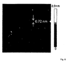
- AFM images showed the formation of monolayers of exfoliated graphene ( Fig. 6 )
- the elemental analysis was carried out using the EuroEA ElementalAnalyser.
- the spectra were recorded with an average of 10 scans, with an energy of 200.00 eV in steps of 1 eV each.
- High-resolution spectra were recorded with an average of 10 scans and an energy of 50.00 eV in steps of 0.1 eV each. The results are shown in Table 1.
- the C / O ratio was determined to be 21.2 and is thus higher than in the exfoliated graph from the prior art.
- Table 1 Elemental analysis and XPS data of the graphite foil and the exfoliated graph (EG) sample element EA XPS Graphite C (at%) 99.57 98.21 Has %) - N / A O (at%) 0.16 1.79 C / O 622 54.9 EG C (at%) 95.01 95.50 Has %) 0.27 N / A O (at%) 4.61 4.50 C / O 20.6 21.2 N / A: Not applicable
- a Si / SiO2 substrate was coated with a monolayer of the exfoliated graphene.
- flakes of grahen were applied according to the Langmuir-Blodgett method. Deionized water was used as the carrier phase.
- a platinum layer was used to fabricate the graphene flake-based field effect transistors of 100 nm thickness applied to the graphene layer by means of ion beam lithography in order to connect the flakes to a gold source / drain electrode.
- the hole mobility was determined from the linear regime of the transfer curves ( Fig. 4 ) certainly.
- the EG-LFP working electrode was made by mixing EG-LFP, activated carbon (super-P) and polyvinylidene difluoride (PVDF) in a mass ratio of 80:10:10. the Mixture was applied to aluminum foil, dried and punched into circular cells with a diameter of 10 mm. These were dried in vacuo at 80 ° C. for 12 hours.
- CR 2032 button cells were fitted with lithium foil (Sigma Aldrich) as the counter electrode and polypropylene as the separator under an inert atmosphere.
- An electrolyte was made from 1M LiPF6 in ethylene carbonate / diethyl carbonate (3: 7 v / v, with 2% by weight vinyl carbonate) and the batteries were filled with it.
- the EG-LFP working electrode was installed.
- Figure 5b illustrates the good stability of the battery capacity over 500 charge and discharge cycles with a Coulombe efficiency of constantly over 95%.
Landscapes
- Chemical & Material Sciences (AREA)
- Organic Chemistry (AREA)
- Inorganic Chemistry (AREA)
- Engineering & Computer Science (AREA)
- Materials Engineering (AREA)
- Chemical Kinetics & Catalysis (AREA)
- Electrochemistry (AREA)
- Metallurgy (AREA)
- Nanotechnology (AREA)
- Carbon And Carbon Compounds (AREA)
- Electrolytic Production Of Non-Metals, Compounds, Apparatuses Therefor (AREA)
Description
- Gegenstand der Erfindung ist ein Verfahren zur Herstellung eines Halbleiter- oder LeiterMaterials aus Monolagen oder mit geschichteter Struktur durch elektrolytische Exfolierung und dessen Verwendung.
- Die Isolierung einzelner Schichten zweidimensional strukturierter oder geschichteter Halbleiter- oder Leitermaterialien ist seit einigen Jahren von Interesse, nicht zuletzt, da die Verwendung dieser Materialien in elektronischen Bauteilen zu enormen Leistungssteigerungen und effizienten Anwendungen führt.
- Ein Beispiel für eine solche isolierte Schicht eines zweidimensional strukturierten oder geschichteten Materials ist Graphen, welches eine Monolage, also eine einzelne, nur eine Atomlage dicke Schicht des Graphits, einer natürlich vorkommenden Erscheinungsform des Kohlenstoffs in Reinform, darstellt. Graphen bezeichnet aber auch Material, in dem einige dieser Monolagen übereinander geschichtet angeordnet sind.
- Graphen kann als ein zweidimensionales Netzwerk aneinandergeketteter Benzolringe verstanden werden, welches u.a. eine enorme elektrische Leitfähigkeit aufweist. Durch seine elektronischen, thermischen, optischen und mechanischen Eigenschaften ist seine Verwendung auf vielen Gebieten der Technik von großem Interesse. Verfahren zur skalierbaren und effizienten Herstellung von qualitativ hochwertigem, möglichst aus der Lösung heraus prozessierbaren Leiter- und Halbleitermaterialien, wie beispielsweise Graphen, sind deshalb Gegenstand intensiver Forschungsarbeiten.
- Die Exfolierung von Graphit zur Herstellung von Graphen, beispielsweise in Form von Flakes oder Flocken stellt eine kostengünstige und verlässliche Strategie zu dessen Gewinnung dar.
- Graphen Schichten als Flocken wurden bereits erfolgreich aus Graphit als Grundmaterial in festem Zustand (siehe beispielsweise i) K. S. Novoselov, A. K. Geim, S. V. Morozov, D. Jiang, Y. Zhang, S. V. Dubonos, I. V. Grigorieva, A. A. Firsov, Science 2004, 306, 666-669; ii) V. Leon, M. Quintana, M. A. Herrero, J. L. G. Fierro, A. d. I. Hoz, M. Prato, E. Vazquez, Chem. Commun. 2011, 47, 10936-10938) oder in flüssiger Phase (siehe beispielweise i) Z. Y. Xia, S. Pezzini, E. Treossi, G. Giambastiani, F. Corticelli, V. Morandi, A. Zanelli, V. Bellani, V. Palermo, Adv. Funct. Mater. 2013, 23, 4684-4693; b) A. Ciesielski, P. Samori, Chem. Soc. Rev. 2014, 43, 381-398.) isoliert.
- Auch durch die Reduktion von Graphenoxid, welches beispielsweise durch die sogenannte Hummers Methode (W.S. Hummers et al. J. Am. Chem. Soc. 1958, 80, 6, 1339) hergestellt werden kann, wurde Graphen erfolgreich hergestellt. Nachteilig verbleiben bei den Reduktionsmethoden jedoch stets Oxidgruppen und weitere Defekte, wie Löcher oder nicht sechs-zählige Ringe innerhalb des Materials. Diese strukturellen Defekte führen zu starken Einschränkungen der elektronischen und thermischen Eigenschaften des so erzeugten Graphens (C. Gómez-Navarro, R. T. Weitz, A. M. Bittner, M. Scolari, A. Mews, M. Burghard, K. Kern, Nano Lett. 2007, 7, 3499-3503).
- Die Behandlung von Graphit in flüssiger Phase in organischen Lösungsmitteln ermöglicht dagegen die Herstellung mit deutlich weniger Defekten (siehe beispielsweise a) F. Bonaccorso, A. Bartolotta, J. N. Coleman, C. Backes, Adv. Mater. 2016, 28, 6136-6166; b) A. Ciesielski, S. Haar, M. EI Gemayel, H. Yang, J. Clough, G. Melinte, M. Gobbi, E. Orgiu, M. V. Nardi, G. Ligorio, V. Palermo, N. Koch, O. Ersen, C. Casiraghi, P. Samorì, Angew. Chem. Int. Ed. 2014, 53, 10355-10361). Nachteilig erreicht man damit nur geringe Ausbeuten an exfoliertem Graphen und kleine Schichtgrößen (J. N. Coleman, Acc. Chem. Res. 2013, 46,14-22).
- Eine weitere Möglichkeit zur Exfolierung von Graphen findet sich in der Elektrolyse von Graphithaltigen Elektroden. Eine Übersicht über die verschiedenen Methoden der elektrochemischen Exfolierung ist beispielsweise in P. Yu et al, Curr. Opinion in Colloid Interface Science, 2015, 20, 329 - 338. gegeben.
- So wird darin in einer Literaturstelle beschrieben, dass Graphen in wässrigen Elektrolyten, enthaltend H2S04 oder H3PO4 mit einer Wechselspannung von +7 - -7 V exfoliert wird.
- Eine weitere Literaturstelle in der o.g. Publikation offenbart die elektrochemische Exfolierung von Graphen aus Graphit, wobei zunächst Propylencarbonat und Lithiumionen zugegeben werden, welche zwischen die Schichten interkalieren In einem weiteren, zweiten Schritt werden Tetrabutylammoniumkationen zugegeben und die Ausdehnung von Graphit wird beobachtet. Zu diesem schon ausgedehnten Graphit wurde dann ein Aryldiazoniumsalz zugegeben, um Graphen zu exfolieren und mit Aryldiazoniumgruppen zu funktionalisieren.
- Legt man an graphithaltige Elektroden eine elektrische Spannung in einer Elektrolysezelle an, so verursacht der fließende elektrische Strom eine Wanderung der geladenen Ionen des Elektrolyten in das Graphit-Material und damit zwischen die einzelnen Schichten (engl. Intercalation - Einschiebung), so dass diese auseinander getrieben werden (C. T. J. Low, F. C. Walsh, M. H. Chakrabarti, M. A. Hashim, M. A. Hussain, Carbon 2013, 54, 1-21).
- Die elektrochemische Exfolierung von Halbleiter- oder Leitermaterialien aus zweidimensional strukturierten oder geschichteten Grundmaterialien, wie beispielsweise Graphit, stellt eine kostengünstige und sehr effiziente Möglichkeit zur Abspaltung einzelner Schichten dar.
- Das zweidimensional strukturierte Grundmaterial kann dabei entweder als Anode in wässrigen Lösungen ionischer Flüssigkeiten (siehe beispielsweise X. Wang, P. F. Fulvio, G. A. Baker, G. M. Veith, R. R. Unocic, S. M. Mahurin, M. Chi, S. Dai, Chem. Commun. 2010, 46, 4487-4489) oder mineralischer Säuren (siehe beispielsweise a) K. S. Rao, J. Sentilnathan, H.-W. Cho, J.-J. Wu, M. Yoshimura, Adv. Funct. Mater. 2015, 25,298-305; b) K. Parvez, R. Li, S. R. Puniredd, Y. Hernandez, F. Hinkel, S. Wang, X. Feng, K. Müllen, ACS Nano 2013, 7, 3598-3606) oder anorganischer Salze (z.B.(a) K. Parvez, Z.-S. Wu, R. Li, X. Liu, R. Graf, X. Feng, K. Müllen, J. Am. Chem. Soc. 2014, 136, 6083-6091; b) S. Yang, S. Brüller, Z.-S. Wu, Z. Liu, K. Parvez, R. Dong, F. Richard, P. Samorì, X. Feng, K. Müllen, J. Am. Chem. Soc. 2015, 137, 13927-13932) geschalten werden. Unter Einfluss des elektrischen Stromes werden dabei Elektronen vom zweidimensional strukturierten Grundmaterial, z.B. Graphit, abgespalten hinterlassen eine positive Ladung an der Anode. Die Anionen des Elektrolyten können dann leicht zwischen die einzelnen Schichten des Grundmaterials, z.B. Graphit, geschoben werden und diese abspalten.
- Auch das Einbringen des Grundmaterials als Kathode ist möglich, u.a. in organischen Lösungsmitteln, enthaltend Lithiumsalze (Z. Zeng, Z. Yin, X. Huang, H. Li, Q. He, G. Lu, F. Boey, H. Zhang, Angew. Chem. Int. Ed. 2011, 50, 11093-11097) oder quartäre Ammoniumsalze (A. J. Cooper, N. R. Wilson, I. A. Kinloch, R. A. W. Dryfe, Carbon 2014, 66, 340-350). Eine elektrisch negative Ausrichtung der Kathode zieht dabei die positiv geladenen Ionen des Elektrolyten an, welche wiederum zwischen die einzelnen Schichten des Grundmaterials dringen und deren Abspaltung erleichtern.
- Die anodische Exfolierung erzielt dabei gute Herstellungsraten (über 10 g/h), dünnschichtiger Graphene Flocken aus 1 bis 3 Monolagen Graphen in hohen Ausbeuten von bis zu 70%. Auch die durchschnittliche Breite der Flocken ist mit bis zu 5 µm relativ hoch. Nachteilig enthält das so hergestellte Graphen jedoch hohe Anteile an Sauerstoffgruppen. Grund dafür sind Sauerstoffradikale wie HO· Oder O·, die während des Herstellungsprozesses durch die Spaltung von Wasser gebildet werden und an die Graphenschichten addieren (siehe K. S. Rao, J. Sentilnathan, H.-W. Cho, J.-J. Wu, M. Yoshimura, Adv. Funct. Mater. 2015, 25, 298-305).
- Die kathodische Exfolierung ermöglicht dagegen die Hestellung reinen Graphens, nachteilig jedoch mit sehr hohen Schichtdicken von mindestens 5 Lagen und relativ niedrigen Herstellungsraten von 0,5 bis 2 g pro Stunde (A. M. Abdelkader, I. A. Kinloch, R. A. W. Dryfe, ACSAppl. Mater. Interfaces 2014, 6, 1632-1639).
- Ein periodischer Wechsel der Funktion der einzelnen Elektroden zwischen Anode und Kathode wurde erstmals von Liu et al. beschrieben (Liu J, Yang H, Zhen SG, Poh CK, Chaurasia A, Luo J, et al. "A green approach to the synthesis of high-quality graphene oxide flakes via electrochemical exfoliation of pencilcore". RSC Adv. 2013; 3, 11745-50.) Eine anodische Spannung von +7 bis -7 V wurde an zwei Graphit Elektroden in wässrigen Elektrolyten, enthaltend Schwefelsäure oder Phosphorsäure, angelegt. Offenbart ist ein periodischer Wechsel der Funktion der einzelnen Elektroden zwischen Anode und Kathode, wobei die Frequenz des Wechsels bei < 0,00166 Hz liegt. Nachteilig bildeten sich dabei sehr dicke geschichtete Graphen Flocken mit einer Dicke von 3 - 9 nm (>10 Atomlagen).
-
EP 2878709 A1 beschreibt ein Verfahren zur Herstellung zweidimensional strukturierter Kohlenstoff-Materialien durch elektrochemische Exfolierung, wobei mindestens eine der Elektroden ein kohlenstoffhaltiges Grundmaterial mit Schichtstruktur umfasst und durch Anlegen einer Spannung mittels Gleichstrom Graphen von dieser Elektrode abgespalten wird. Die verwendete Elektrolytlösung enthält ein Ammonium-Kation und ein anorganisches Schwefelhaltiges Anion. Das Ammonium-Kation kann dabei 4 Alkyl-Reste am Stickstoff aufweisen. In einer Ausführungsform kann während der Elektrolyse die Polarität der Elektroden umgekehrt werden. - Auch von Su et al. (Su C.Y, Lu A.Y, Xu Y, Chen F.R, Khlobystov A.N, Li L.J. "High-quality thin graphene filmsfrom fast electrochemical exfoliation". ACS Nano 2011; 5:2332-9) ist ein Verfahren für die elektrolytische Exfolierung von Graphen aus Graphit bekannt. Dabei wird eine Graphitelektrode zunächst als Anode geschaltet, eine Platinelektrode bildet die Gegenelektrode. Als Elektrolyt dient eine wässrige Lösung, enthaltend Schwefelsäure und Kaliumhydroxid, um den pH-Wert bei 1,2 einzustellen.
- Zunächst wird an die Graphit-Elektroden eine niedrige Spannung von +2,5 V angelegt, um die Oberfläche der Elektrode zu befeuchten und das Eindringen der Anionen zwischen die Graphit-Schichten zu forcieren. Nachteilig erfolgt dabei auch in hohem Maße eine Oxidation des Graphits. Die Elektrolyse wird mittels Gleichstrom betrieben, welcher periodisch die Richtung wechseln kann. Wird die Elektrode als Kathode geschaltet, so erfolgt die Reduktion des Graphenoxids. Die Umkehr der Polarität der Elektroden erfolgt mit einer Periodendauer von 2s bis 1 min. Nachteilig beträgt die Ausbeute an exfoliertem Graphen nur 5 bis 8 m% des eingesetzten Graphits.
- Aufgabe der Erfindung ist die Bereitstellung eines kostengünstigen, effizienten und skalierbaren Verfahrens zur Herstellung von Leiter- und/oder Halbleitermaterialien, insbesondere Graphen, aus zweidimensional strukturiertem, geschichteten Grundmaterialien mittels Exfolierung.
- Gelöst wird die Aufgabe durch ein Verfahren zur Herstellung eines Halbleiter- oder Leitermaterials aus einem zweidimensional geschichtet strukturierten Grundmaterial durch elektrolytische Exfolierung, in einer Elektrolysezelle, umfassend mindestens ein Elektrodenpaar aus einer ersten und einer zweiten Elektrode, und eine Elektrolytlösung, enthaltend mindestens ein gelöstes Tetraalkylammoniumsalz oder mindestens ein gelöstes Tetraalkylammoniumsalz und Schwefelsäure
wobei das Anion des Tetraalkylammoniumsalzes ausgewählt ist aus Sulfat, Hydrogensulfat, Thiosulfat, Sulfit, Nitrat oder Hydroxid,
wobei beide Elektroden des Elektrodenpaares das zweidimensional geschichtet strukturierte Grundmaterial enthalten, und wobei während der Elektrolyse die Polarität der ersten und zweiten Elektrode periodisch umgekehrt wird, wobei die Umkehr der Polarität der Elektroden durch Anlegen einer Wechselspannung erfolgt und wobei die Umkehrfrequenz der Wechselspannung bevorzugt 0,001 bis 10 Hz beträgt. - Im Sinne der Erfindung ist ein Leiter- oder Halbleiter-Material ein elektrisch leitendes Material mit einer hochgeordneten, geschichteten Struktur, bestehend aus einer Monolage des Materials oder aus mehreren übereinander angeordnete Lagen des Materials. Das HalbleiterMaterial weist eine spezifische Bandlücke auf, die aus der Energiedifferenz zwischen dem Valenzband und Leitungsband gebildet wird.
- In einer Ausführungsform ist das Halbleiter- oder Leiter-Material ausgewählt aus Graphen, Graphenderivaten, kohlenstoffbasierten Halbleiter- oder Leiter-Polymeren und/oder geschichteten Chalcogeniden der allgemeinen Formel MQ2, wobei gilt M = Ti, Zr, Hf, V, Nb, Ta, Mo oder W und wobei gilt Q = O, S, Se oder Te.
- In einer Ausführungsform ist das zweidimensional geschichtet strukturierte Grundmaterial ausgewählt aus Graphit, kohlenstoffbasierten Halbleiter- oder Leiter-Polymeren in Form von zweidimensional strukturiertem Grundmaterial und/oder geschichteten Chalcogeniden. Graphit kann dabei natürlich vorkommendes oder synthetisch hergestelltes Graphit sein.
- Die Exfolierung des Halbleiter- oder Leitermaterials aus dem oder von dem zweidimensional, geschichtet strukturierten Grundmaterial erfolgt elektrolytisch in einer Elektrolysezelle, welche mindestens ein Elektrodenpaar enthält. Ein Elektrodenpaar umfasst eine erste Elektrode E1 und eine zweite Elektrode E2. Beide Elektroden des Elektrodenpaares enthalten das Grundmaterial.
- In einer Ausführungsform enthält mindestens eine Elektrode das Grundmaterial in Form von Flocken, Pulver, Fasern, Folien, Stücken, Pasten oder eine Mischung dieser. Die Elektrode kann auch eine einzelne Flocke des Grundmaterials sein, oder mehrere dieser Flocken, die entweder aneinandergepresst oder durch ein leitfähiges Material miteinander verbunden sind.
- In einer Ausführungsform ist die Elektrolytlösung der Elektrolysezelle eine wässrige Lösung.
- In einer weiteren Ausführungsform enthält die Elektrolytlösung mindestens ein polares organisches Lösungsmittel, beispielsweise Propylencarbonat oder Acetonitril.
- Zu Beginn der Elektrolyse wird das mindestens eine Elektrodenpaar in die Elektrolytlösung eingebracht und die Elektrolyse so betrieben, dass sich die Polarität der ersten und der zweiten Elektrode periodisch umkehrt.
- Erfindungsgemäß erfolgt die Umkehr der Polarität durch Anlegen einer Wechselspannung zwischen der ersten und der zweiten Elektrode. Periodisch wechselt damit die Funktion jeder Elektrode zwischen Anode und Kathode.
- In einer Ausführungsform beträgt die Spannung, bei welcher die Elektrolyse betrieben wird, +/- 2 V bis +/-20 V, bevorzugt +/- 5V bis +/- 15 V, besonders bevorzugt +/-10 V.
- Beide Elektroden des Elektrodenpaares enthalten das zweidimensional geschichtet strukturierte Grundmaterial.
- Ist eine Elektrode gerade als Anode geschalten, so erfolgt im Anodenbereich zunächst die Bildung von sauerstoffhaltigen Radikalen wie HO oder O welche die Grenzflächen oder intrinsischen Defekte des Grundmaterial angreifen und daran addieren, wobei sich Oxide des Grundmaterials bilden. Gleichzeitig werden die Randschichten des Grundmaterials auseinandergetrieben, sodass sich die Anionen des Elektrolyten weit dazwischenschieben können und den Abstand der einzelnen Schichten des Grundmaterials aufdehnen.
- Wird im nächsten Moment die Polarität der Elektrode umgekehrt, erfolgt die Reduktion der Anionen, wobei sich ein Gas bildet, das die einzelnen Schichten des Grundmaterials noch weiter auseinandertreibt. Gleichzeitig erfolgt eine Reduktion der Sauerstofffunktionalitäten an der nun als Kathode geschalteten Elektrode, womit aus den Oxiden des Grundmaterials wieder das Grundmaterial entsteht und Sauerstoffdefekte entfernt werden.
- Auch die Interkalation der Kationen des Elektrolyten erfolgt und führt zur Aufweitung des Abstands zwischen den Schichten, soweit, dass die zwischenmolekularen Kräfte überwunden werden können, sodass sich einzelne Schichten von der Elektrode abspalten. Somit erfolgt die Exfoliation einer Monolage oder einer dünnen Schicht des Grundmaterials von der Elektrode.
- Da beide Elektroden des Elektrodenpaares das zweidimensional geschichtet strukturierte Grundmaterial enthalten erfolgt die Exfolierung simultan an beiden Elektroden E1 und E2.
- Es laufen nun im ständigen Wechsel die in den beiden vorhergehenden Abschnitten beschriebenen Prozess an beiden Elektroden E1 und E2 ab. Während also an der einen Elektrode, beispielsweise E1, die anodische Oxidation und Interkalation der Elektrolytanionen stattfindet, werden an der anderen Elektrode E2 diese eingeschobenen Anionen und auch die Sauerstoffdefektstellen reduziert und durch die entstehenden Gase und die Interkalation der Elektrolytkationen die Schichten des Grundmaterials exfoliert.
- Kehrt sich die Polarität um, so findet die Abspaltung der Schichten an der E1 statt, bei erneuter Umkehr der Polarität wieder an der E2.
- Es werden also im ständigen Wechsel an E1 und E2 Schichten des Grundmaterials abgespalten.
- Überraschend hat sich gezeigt, dass die Exfolierung an der Elektrode, die zuerst als Kathode geschalten wird, unter Verwendung von Wechselstrom vergleichbar effizient ist, wie die Exfolierung an der Elektrode, die zuerst als Anode geschalten wird.
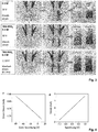
- Führt man selbigen Versuch unter Verwendung von Gleichstrom durch und kehrt die Polarität der Elektroden manuell periodisch um, so erfolgt eine gute Exfolierung an der Elektrode, die zuerst als Anode geschaltet war. Allerdings zeigt findet kaum eine Exfolierung an der Elektrode statt, die zuerst als Kathode geschaltet war (siehe
Fig. 3 ). - Vorteilhaft können in dieser Ausführungsform durch das erfindungsgemäße Anlegen eines Wechselstromes / einer Wechselspannung zwischen beiden Elektroden eine simultane Exfoliation an beiden Elektroden und hohe Ausbeuten an exfoliertem Material, also an Halbleiter- oder Leitermaterial erzeugt werden.
- Ein weiterer Vorteil dieser Ausführungsform liegt darin, dass keine kostenintensiven Edelmetall-Gegenelektroden, wie beispielsweise von Su et al. verwendet (Su C.Y, Lu A.Y, Xu Y, Chen F.R, Khlobystov A.N, Li L.J. "High-quality thin graphene films from fast electrochemical exfoliation". ACS Nano 2011; 5:2332-9), benötigt werden, um die Elektrolyse durchzuführen. Würde an Stelle des Platins ein unedles Metall verwendet, würde die Umkehr der Polarität zu anodischen Potentialen ein Auflösen des Materials zur Folge haben und ein regelmäßiges Ersetzen der Elektrode erfordern. Nachteilig würde außerdem das Halbleiter- oder Leitermaterial mit den Ionen des Elektrodenmaterials kontaminiert werden.
- Bevorzugt beträgt die Umkehrfrequenz des Wechselstromes zwischen 0,001 bis 10 Hz.
- In Ausführungsformen der Erfindung beträgt die Umkehrfrequenz des Wechselstromes 0,01 bis 10 Hz, bevorzugt 0,05 bis 1 Hz, insbesondere 0,1 bis 0,2 Hz.
- Die Polarität der Elektroden kann also periodisch alle 0,1 bis 1000s wechseln, bevorzugt wechselt sie alle 1 bis 100 s, besonders bevorzugt alle 1 bis 20s, insbesondere alle 5 bis 10 s.
- Durch das schnelle, periodische Umschalten der Polarität erfolgt vorteilhaft der Prozess aus Oxidation/Aktivierung des Grundmaterials und Reduktion/Exfolierung schneller und effizienter. Da die Stufe der Oxidation nicht so lang andauert wie aus dem Stand der Technik bekannt, sondern innerhalb einer kurzen Periode sofort die Reduktion erfolgt, enthält das exfolierte Leiter- oder Halbleitermaterial vorteilhaft weniger Sauerstoffdefekte.
- Vorteilhaft erhöht sich durch das Anlegen eines Wechselstromes der Anteil an Graphenflocken aus Mono- und Bilagen, also Graphen, das nur aus einer oder zwei atomaren Lagen an Kohlenstoff besteht. Hohe Schichtdicken, wie sie sonst aus der kathodischen Exfolierung bekannt sind, werden vorteilhaft vermieden.
- Gleichzeitig werden Flocken des Halbleiter- oder Leitermaterials mit größerer Ausdehnung im zweistelligen Mikrometerbereich erhalten.
- In einer Ausführungsform werden pro Gramm Grundmaterial, das in die Elektrolytlösung taucht, mindestens 100 ml Elektrolytlösung verwendet.
- Die Elektrolytlösung enthält neben dem Lösungsmittel mindestens ein gelöstes Tetraalkylammoniumsalz oder mindestens ein gelöstes Tetraalkylammoniumsalz und Schwefelsäure.
- In einer erfindungsgemäßen Variante enthält die Elektrolytlösung mindestens ein gelöstes Tetraalkylammoniumsalz.
- In einer weiteren Variante enthält die Elektrolytlösung eine Mischung aus Schwefelsäure und mindestens einem gelösten Tetraalkylammoniumsalz.
- In einer Ausführungsform beträgt die Konzentration des Salzes oder der Schwefelsäure oder die Gesamtkonzentration von Salz und Schwefelsäure in der Elektrolytlösung mindestens 0,001 M, bevorzugt 0,001 bis 2 M, besonders bevorzugt 0,005 bis 1, 5 M, insbesondere 0,05 bis 0,2 M.
- Das in der Elektrolytlösung gelöste Salz ist ausgewählt aus Tetraalkylammoniumsalzen.
- Das Kation des Salzes entspricht also der allgemeinen Formel NR4 +, mit R = C1- bis C5-Alkyl, wobei alle R gleich oder voneinander verschieden sein können.
- Erfindungsgemäß ist das Anion des Salzes ausgewählt aus Sulfat (S04 2-), Hydrogensulfat (HSO4 -), Thiosulfat (S2O3-), Sulfit (SO3 2-), Nitrat (NO3-) oder Hydroxid (OH-), bevorzugt Sulfat und/oder Hydrogensulfat.
- Die Anionen haben einen Durchmesser, mit dem sie während der anodischen Oxidation zwischen die Schichten des zweidimensional geschichtet strukturierten Grundmaterials dringen können, so dass sie den Abstand zwischen den einzelnen Schichten aufweiten. Sulfatanionen haben beispielsweise einen Durchmesser von 0,46 nm.
- Die anschließende Gasbildung durch die Reduktion der Anionen treibt die Schichten noch weiter auseinander. Tetrabutylammoniumsalze haben den Vorteil, dass sie, während die Elektrode als Kathode geschaltet ist, anders als Kationen kleinen Durchmessers wie beispielsweise H+ oder Li+ oder Na+, den Abstand zwischen den Schichten auch durch ihre Molekülgröße noch weiter aufdehnen können.
- Die bisher im Stand der Technik verwendeten Tetramethyl- oder Tetraethyl-Ammoniumsalze führten jedoch trotzdem nur zu geringen Ausbeuten und niedrigen Produktionsraten an Leiteroder Halbeitermaterial wie Graphen.
- In einer Ausführungsform ist das Tetraalkylammoniumsalz Tetrabutylammoniumsulfat (TBAS) und/ oder Tetrabutlyammoniumhydrogensulfat, deren Kation jeweils ein Tetrabutylammonium-Kation (C4H9)4N+ (TBA) ist.
- Vorteilhaft weist das TBA-Kation durch die Butylketten eine flexible Struktur auf, sodass es im flachen, horizontalen Zustand einen vertikalen Durchmesser von 0,47 nm hat und einfach zwischen die durch die anodische Reaktion schon leicht aufgeweiteten Schichten des Grundmaterials dringen kann. Durch den großen vertikalen Durchmesser des TBA Kations im aufgestellten, vertikalen Zustand von 0,89 nm kann es dann die Schichten so weit auseinanderdehnen, dass die van-der-Waals Kräfte, die zwischen den einzelnen Schichten des Grundmaterials herrschen, überwunden werden und die Schichten so auseinanderdriften.
- Vorteilhaft resultiert daraus eine hohe Produktionsrate an exfoliertem Leiter- oder Halbleitermaterial, mit geringem Sauerstoffgehalt (
Fig.1 ). Werden beispielsweise 5 Elektrodenpaare, bestehend aus je 2 Graphitfolien mit einer Masse von 1 g gleichzeitig im erfindungsgemäßen Verfahren eingesetzt, so werden Produktionsraten von mindestens 5,5 g exfoliertem Graphen in 15 min, also > 20 g/ h erhalten. - Hohe Ausbeuten bis 85%, bezogen auf die Ausgangsmasse des Grundmaterials, welches in die Elektrolytlösung eintaucht, werden erreicht und man erhält exfoliertes Leiter- oder Halbleitermaterial mit sehr geringen Schichtdicken bzw. sogar einzelnen isolierten Monolagen.
- Auch wenn nur eine der beiden Elektroden eines Elektrodenpaares das zweidimensional strukturierte, geschichtete Grundmaterial enthält, so erreicht man hohe Ausbeuten an Leiteroder Halbleitermaterial von bis 85% bezogen auf die Ausgangsmasse des Grundmaterials, welches in die Elektrolytlösung eintaucht.
- Enthält die Elektrolytlösung Schwefelsäure, so gestaltet sich das erfindungsgemäße Verfahren vorteilhaft kostengünstig und umweltfreundlicher, da, im Gegensatz zur Verwendung von Ammoniumsalzen, keine stickstoffhaltigen Abwässer entstehen.
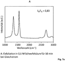
- Gegenüber den im Stand der Technik verbreiteten Verfahren der Exfolierung mit Gleichstrom, unter der Verwendung von Schwefelsäure als Elektrolyt, werden hierbei vergleichbare Produktionsraten erzielt. Durch die wechselnden Polaritäten (Oxidation und Reduktion) im erfindungsgemäßen Verfahren wird allerdings die Oxidation des erhaltenen Materials deutlich verringert, und man erhält Material mit wesentlich geringerer Defektdichte (siehe
Fig. 7 ) - In einer Ausführungsform wird die Elektrolyse beendet, wenn das gesamte Grundmaterial exfoliert wurde. In einer weiteren Ausführungsform wird die Elektrolyse bereits vorher beendet.
- In einer Ausführungsform erfolgt nach der Elektrolyse die Trennung des exfolierten Materials von der Elektrolytlösung. Dies kann nach den aus dem Stand der Technik bekannten Methoden wie Filtration, Zentrifugation oder Sedimentation erfolgen.
- In einer Ausführungsform ist das das zweidimensional geschichtet strukturierte Grundmaterial Graphit. Im erfindungsgemäßen Verfahren werden Ausbeuten an Graphen von 80% bezogen auf das Graphit erreicht. Die Produktionsraten liegen bei 20 g/h im Labormassstab.
- Vorteilhaft lässt sich das erfindungsgemäße Verfahren durch Auswahl der Größe der Elektrolysezelle und der eingesetzten Menge an Grundmaterial individuell nach oben skalieren, sodass die Produktion der Leiter- oder Halbleitermaterialien im technischen Maßstab in hohen Ausbeuten und hohen Produktionsraten möglich ist.
- Gegenstand der Erfindung ist auch die Verwendung des im erfindungsgemäßen Verfahren hergestellten Halbleiter- oder Leitermaterials in Dünnschicht-Elektroden.
- Dafür können beispielsweise aus dem erfindungsgemäßen Verfahren hergestellte Graphenflocken aus einer Dispersion auf Substrate, wie Glas, Siliciumträger oder ITO transferiert werden. Es ergeben sich Graphenfilme mit sehr geringen Schichtwiderständen.
- Gegenstand der Erfindung ist auch die Verwendung des im erfindungsgemäßen Verfahren hergestellten Halbleiter- oder Leitermaterials in Komposit-Materialien. So können sie mit leitfähigen Polymeren wie PEDOT:PSS gemischt werden, um diese als Bottom-Elektroden in verschiedenen elektronischen Bauelementen einzusetzen.
- Die Graphenflocken können beispielsweise auch mit Nanopartikeln verknüpft werden und damit als High Performance Anodenmaterial für Lithiumspeicher dienen (J. Am. Chem. Soc., 2015, 137, 5576).
- Gegenstand der Erfindung ist auch die Verwendung des im erfindungsgemäßen Verfahren hergestellten Halbleiter- oder Leitermaterials in Batterien oder Akkumulatoren. Dazu kann beispielsweise Graphen mit kommerziell erhältlichem Kathodenmaterial, wie beispielsweise LiFePO4 zu geringen Gewichtsanteilen, wie beispielsweise 2 m% gemischt und zur Herstellung einer Batterie verwendet werden. Die so hergestellten Graphen-LiFePO4 Komposit- Batterien weisen eine hohe Entladungskapazität auf (siehe Ausführungsbeispiel 3).
- Gegenstand der Erfindung ist auch die Verwendung von Tetrabutylammoniumsulfat und/oder Tetrabutylammoniumhydrogensulfat in einem erfindungsgemäßen Verfahren zur Herstellung von Graphen, gekennzeichnet durch einen Anteil an Flocken mit einer Schichtdicke von 1-3 Monolagen von >70% und/oder durch ein C/O Verhältnis von 10 bis 30, und/oder durch einen Sauerstoffgehalt von 0 bis 9 at% und/oder durch eine Lochmobilität von 350 bis 1000 cm2 * V-1 * S-1 .
- Nachfolgende Abbildungen und Ausführungsbeispiele sollen die Erfindung näher erläutern, ohne sie jedoch darauf zu beschränken.
- Dabei zeigen:
-
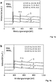
Fig. 1 : XPS Aufnahmen von exfoliertem Graphen aus einer Wechselstrom-Elektrolyse in wässrigen Lösungen von a) Tetramethylammoniumhydrogensulfat und b) Tetrabutylammoniumhydrogensulfat.
Die Frequenz des Wechselstromes wurde zwischen 0,05 Hz und 0,25 Hz variiert. Die Arbeitsspannung betrug +/- 10 V, die Konzentration des Elektrolyten betrug 0,1M in Wasser. Es ist deutlich zu sehen, dass der Sauerstoffgehalt des Graphens, wenn es aus Lösung a) exfoliert wird, wesentlich höher ist, als der des Graphens aus Lösung b). Die Verwendung von Tetrabutylammoniumhydrogensulfat führt also zu Graphen mit einem geringeren Sauerstoffgehalt.
Ein geringerer Sauerstoffgehalt bedeutet weniger Defektstellen und damit erhöhte Leitfähigkeit des Graphens. -
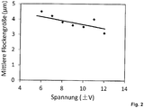
Fig. 2 : Die Abhängigkeit der Flockengrösse des exfolierten Graphens von der Arbeitsspannung der Elektrolyse in einer 0,1 M Lösung von Tetrabutylammoniumhydrogensulfat. Die Frequenz des Wechselstromes beträgt 0,1 Hz. Diese Untersuchung zeigt, dass sich mit höherer Spannung die Grösse der Flocken wieder verringert. So wird gezeigt, dass durch die angelegte Spannung die laterale Partikelgröße individuell gesteuert werden kann. Damit können gezielt Materialien für Anwendungen mit unterschiedlichen Ansprüchen an die Partikelgröße hergestellt werden. -
Fig. 3 : Untersuchung der Auswirkung von Gleichstrom (direct current,Fig. 3 oben und mitte) und Wechselstrom (Alternating current,Fig. 3 , untere Abbildung) während der elektrolytischen Exfolierung von Graphen.
In allen drei Versuchen wurden jeweils zwei Graphitfolien als Elektrodenpaar geschaltet, sodass an beiden Elektroden Graphen exfoliert werden könnte.
Es zeigt sich, dass unter der Verwendung von Gleichstrom jeweils nur die Elektrode Graphenschichten exfoliert, die zuerst als Anode geschalten wird. Die Elektrode, die zuerst als Kathode geschalten ist, zeigt nur wenig exfoliertes Graphen. (oben und mitte)
Bei der Verwendung von Wechselstrom unter gleichen Bedingungen (unten) zeigt gleichwertig gute Exfolierung von Graphen an beiden Elektroden. -
Fig. 4f und 4g zeigen die I-V Charakteristiken der Graphenflocken-basierten Feldeffekttransistoren, hergestellt nach Ausführungsbeispiel 2. Es ergibt sich daraus eine Lochmobilität für das erfindungsgemäß hergestellte Graphen von 430 cm2 * V-1 * S-1. -
Fig. 5a zeigt ein Spannungsprofil der EG-LFP Batterie, die mit einer Kapazität von 1C = 170 mAh/g eingesetzt wird und nach dem 20. Zyklus (1) eine Kapazität von 157 mAh/g aufweist. Auch nach dem 200. (2) bzw. 500. (3) Zyklus weist sie noch eine Kapazität von 167 mAh/g auf. -
Fig. 5b verdeutlicht die gute Stabilität der Batteriekapazität über 500 Lade- und Entladezyklen mit einer Coulombeffizienz von konstant über 95%. -
Fig. 6 zeigt eine AFM Aufnahme exfolierter Graphenflocken. Anhand des Höhenprofils ist erkennbar, dass es sich um eine Monolage Graphen handelt. -
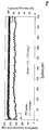
Fig. 7 zeigt die Ramanspektren von exfoliertem Graphen zum Nachweis der Anwesenheit von Defektstellen im Material. In Graph A ist sichtbar, dass die Exfolierung mit Schwefelsäure als Elektrolyten unter der Verwendung von Gleichstrom eine hohe Dichte an Sauerstoffdefekten mit sich bringt. (hohe Signalstärke bei 1000 bis 1700 cm-1). - Die Verwendung von Schwefelsäure in einer Elektrolyse unter Wechselstrom (B) zeigt dagegen deutlich weniger Sauerstoffdefekte auf, ähnlich wie die Verwendung von Tetrabutylammoniumhydrogensulfat (C).
- Die Exfolierung von Graphen wurde mit einem Elektrodenpaar, bestehend aus zwei Graphitfolien (1,5 * 5 cm, 100mg pro Folie) (Alfa Aesar) durchgeführt.
- Die Elektroden des Elektrodenpaares wurden parallel in einem festen Abstand von 1,5 cm angeordnet. Die Elektrolytlösung wurde hergestellt durch Lösen von Tetrabutylammoniumhydrogensulfat Pulver in entionisiertem Wasser (0,1 M, 1,7 g des Salzes in 50 ml Wasser). Der pH-Wert der Elektrolytlösung wurde mit NaOH auf 7 eingestellt. Ein Wechselstrom mit einer Arbeitsspannung von +/- 10 V und einer Frequenz von 0,1 Hz wurde angelegt, um die Graphenschichten abzuspalten. Die Ausrichtung der anodischen Arbeitsspannung wechselte alle 5 s von positiven zu negativen Werten und zurück. Um ein Überhitzen der Elektrolysezelle zu verhindern, wurde diese während des gesamten Exfolierungsprozess in einem Eisbad gekühlt.
- Das in der Elektrolytlösung suspendierte Graphen wurde mittels 0,2 µm PTFE Membranfilter abgetrennt und dreimal mit Wasser und dreimal mit Ethanol gewaschen, um die Überreste des Elektrolyten zu entfernen.
- Es wurden 120 mg Graphen generiert.
- Für eine Herstellung von Graphen im größeren Maßstab wurden 5 Elektrodenpaare aus Graphitfolien (6 * 12 cm, 1,02 g pro Folie) mit je 2 cm Abstand zwischen jedem Elektrodenpaar in Reihe geschalten.
- Die Elektrolyse wurde durchgeführt unter denselben Bedingungen, wie in Ausführungsbeispiel 1 aufgeführt. Es wurden jedoch 1000 ml Elektrolytlösung einer Konzentration von 0,1 M verwendet (34 g Tetrabutylammoniumhydrogensulfat in 1000 ml entionisiertem Wasser). Die Exfolierung endete automatisch, wenn das Graphit-Material aufgebraucht war.
- Das in der Elektrolytlösung suspendierte Graphen wurde mittels 0,2 µm PTFE Membranfilter abgetrennt und dreimal mit Wasser und dreimal mit Ethanol gewaschen, um die Überreste des Elektrolyten zu entfernen. Es wurden 5,5 g Graphen in 15 min generiert.
- Anschließend wurde das Graphen Pulver im Ultraschallbad in N,N-dimethylformamid dispergiert und konnte so gelagert oder weiterverwendet werden. Dazu wurden 120 mg Graphen in 1 L DMF dispergiert, um eine 0,1 mg/ ml Graphen in DMF Dispersion zu erhalten.
- AFM Aufnahmen zeigten die Bildung von Monolagen von exfoliertem Graphen (
Fig. 6 ) - Die Elementaranalyse wurde mittels EuroEA ElementalAnalyser durchgeführt.
- Die XPS Analyse wurde an einem Thermo Scientific K-Alpha X-ray Photoelektronspectrometer durchgeführt mit einem Kammerdruck von ∼ 10-8 - 10-9 mbar mit einer Al Anode als Röntgenquelle (x-ray radiation = 1486.7 eV) mit Punktgrößen von 400 µm. Die Spektren wurden mit durchschnittlich 10 Scans aufgenommen, mit einer Energie von 200,00 eV in Stufen von je 1 eV. Hochauflösende Spektren wurden mit durchschnittlich 10 Scans und einer Energie von 50,00 eV in Stufen von je 0,1 eV aufgenommen. Die Ergebnisse sind in Tabelle 1 dargestellt.
- Der Sauerstoffanteil des exfolierten Graphens wurde mit 4,5 at% (= Atomprozent = Anteil der Anzahl der Atome an der Gesamtzahl aller Atome in der Verbindung) bestimmt. Das C/O Verhältnis wurde mit 21,2 bestimmt und liegt damit höher als in exfoliertem Graphen aus dem Stand der Technik.
Tabelle 1 - Elementaranalyse und XPS Daten der Graphitfolie und des exfolierten Graphens (EG) Sample Element EA XPS Graphite C (at %) 99.57 98.21 H (at %) -- N/A O (at %) 0.16 1.79 C/O 622 54.9 EG C (at %) 95.01 95.50 H (at %) 0.27 N/A O (at %) 4.61 4.50 C/O 20.6 21.2 N/A: Not applicable - Zur Bestimmung des Schichtwiderstandes wurde ein Si/SiO2 Substrat mit einer Monolage des exfolierten Graphens beschichtet. Dazu wurden Grahenflocken nach der Langmuir-Blodgett-Methode aufgetragen. Entionisiertes Wasser wurde als Trägerphase verwendet.
- Es wurde 1 ml einer DMF Dispersion von exfoliertem Graphen (EG) (0,05mg EG /ml DMF) mit 3 ml Chloroform versetzt und die Mischung vorsichtig mittels Spritze auf eine Wasseroberfläche getropft. Mittels eines Stücks Filterpapier wurde die Oberflächenspannung des Wassers während der Kompression des EG Films kontrolliert. Die erreichte Oberflächenspannung betrug 20 mM/m. Durch vertikales Dip-coating wurde ein dünner Film an EG auf das Silizium-Substrat (mit einer Oxidschicht von 300 nm) transferiert. Die Proben wurden vorsichtig mit entionisiertem Wasser gewaschen und bei 200°C für 30 min im Vakuum getrocknet.
- Zur Fabrikation der Graphenflocken-basierten Feldeffekttransistoren wurde eine Platin-schicht von 100 nm Dicke mittels lonenstrahllithographie auf die Graphenschicht aufgetragen, um die Flocken mit einer Gold source/drain Elektrode zu verbinden.
- Die Lochmobilität wurde aus dem linearen Regime der Transferkurven (
Fig. 4 ) bestimmt. Man verwendete dazu folgende Gleichung:
- Es ergibt sich aus den I-V Charakteristiken (siehe
Fig. 4 , f und g) eine Lochmobilität von 430 cm2 * V-1 * S-1 . - Der Schichtwiderstand einer einzelnen Monolage EG wurde an selbigem Bauteil gemessen, der Wert wurde durch folgende Gleichung bestimmt:

Es ergab sich ein Schichtwiderstand von 1,98 kΩ sq-1. - Der Schichtwiderstand des EG Films wurde in einem 4 Punkt - Probensystem mit einem Keithley 2700 Multimeter (Probenabstand: 0.635 mm, Rs=4.532 V/I) gemessen.
- Alle Untersuchungen wurden in einer Glove Box, die mit Inertgas gefüllt war, durchgeführt. Verwendet wurde ein Keithley SCS 4200 Semiconductor System.
- Zur Veranschaulichung des Potentials der Verwendung von erfindungsgemäß hergestelltem Graphen in Batterieapplikationen, wurde kommerziell erhältliches Kathodenmaterial (LiFePO4 Pulver, 20 mg, Partikelgrösse < 5µm, von Sigma Aldrich) in 40 ml DMF suspendiert um eine homogene Dispersion zu ergeben. Diese wurde anschließend mit 8 ml einer Graphendispersion (0,05mg/ml in DMF) vermischt und im Ultraschallbad behandelt. Die sich so ergebenden Graphen-beschichteten LiFePO4 (EG-LFP) Partikel wurden abfiltriert und über Nacht im Ofen bei 100°C getrocknet.
- Die EG-LFP Arbeitselektrode wurde hergestellt durch Vermischen von EG-LFP, Aktivkohle (super-P) und Polyvinylidendifluorid (PVDF) in einem Massenverhältnis von 80:10:10. Die Mischung wurde auf eine Aluminiumfolie aufgetragen, getrocknet und in kreisförmige Zellen mit einem Durchmesser von 10 mm gestanzt. Diese wurden für 12 Stunden im Vakuum bei 80°C getrocknet.
- Knopfzellen des Typs CR 2032 wurden unter inerter Atmosphäre mit Lithiumfolie (Sigma Aldrich) als Gegenelektrode bestückt und Polypropylen als Separator. Ein Elektrolyt wurde hergestellt aus 1M LiPF6 in Ethylencarbonat/Diethylcarbonat (3:7 v/v, mit 2 m% Vinylcarbonat) und die Batterien damit befüllt. Die EG-LFP Arbeitselektrode wurde eingebaut.
- Alle Untersuchungen zur Bestimmung der Ladungs- und Entladungskurven und Zyclen wurden mittels eines LAND Batterie Systems unter Raumluftbedingungen durchgeführt.
-
Fig. 5a zeigt ein Spannungsprofil der EG-LFP Batterie, die mit einer Kapazität von 1C = 170 mAh/g eingesetzt wird und nach dem 20. Zyklus (1) eine Kapazität von 157 mAh/g aufweist. Auch nach dem 200. (2) bzw. 500. (3) Zyclus weist sie noch eine Kapazität von 167 mAh/g auf. -
Fig. 5b verdeutlicht die gute Stabilität der Batteriekapazität über 500 Lade- und Entladezyklen mit einer Coulombeffizienz von konstant über 95%.
Claims (11)
- Verfahren zur Herstellung eines Halbleiter- oder Leitermaterials aus einem zweidimensional geschichtet strukturierten Grundmaterial durch elektrolytische Exfolierung, in einer Elektrolysezelle, umfassend mindestens ein Elektrodenpaar aus einer ersten und einer zweiten Elektrode, und eine Elektrolytlösung, enthaltend mindestens ein gelöstes Salz oder ein gelöstes Salz und Schwefelsäure , wobei beide Elektroden eines Elektrodenpaares das zweidimensional geschichtet strukturierte Grundmaterial enthalten , und
wobei das Salz ausgewählt ist aus Tetraalkylammoniumsalzen, und
wobei das Anion des Salzes ausgewählt ist aus Sulfat (SO4 2-), Hydrogensulfat (HSO4 -), Thiosulfat (S2O3 -), Sulfit (SO3 2-) , Nitrat (NO3-) oder Hydroxid (OH-) , und
wobei während der Elektrolyse die Polarität der ersten und zweiten Elektrode periodisch umgekehrt wird,
dadurch gekennzeichnet, dass die Umkehr der Polarität der Elektroden durch Anlegen einer Wechselspannung erfolgt. - Verfahren nach Anspruch 1, dadurch gekennzeichnet, dass das Halbleiter- oder LeiterMaterial ausgewählt ist aus Graphen, kohlenstoffbasierten Halbleiter- oder Leiter-Polymeren und/oder geschichteten Chalcogeniden.
- Verfahren nach einem der Ansprüche 1 oder 2, dadurch gekennzeichnet, dass das zweidimensional strukturierte Grundmaterial ausgewählt ist aus Graphit, kohlenstoffbasierten Halbleiter- oder Leiter-Polymeren in Form von zweidimensional strukturiertem Grundmaterial und/oder geschichteten Chalcogeniden.
- Verfahren nach einem der Ansprüche 1 bis 3, dadurch gekennzeichnet, dass die Wechselspannung +/- 2 V bis +/-20 V beträgt.
- Verfahren nach einem der Ansprüche 1 bis 4, dadurch gekennzeichnet, dass die Umkehrfrequenz der Wechselspannung 0,001 bis 10 Hz beträgt.
- Verfahren nach einem der Ansprüche 1 bis 5, dadurch gekennzeichnet, dass das Tetra-alkylammoniumsalz Tetrabutylammoniumsulfat und/oder Tetrabutylammoniumhydrogensulfat ist.
- Verfahren nach einem der Ansprüche 1 bis 6, dadurch gekennzeichnet, dass mindestens eine Elektrode das Grundmaterial in Form von Flocken, Brocken, Folien, Fasern oder einer Mischung dieser enthält.
- Verwendung des Halbleiter- oder Leiter-Materials, hergestellt in einem Verfahren gemäß einem der Ansprüche 1 bis 7 in Dünnschicht-Elektroden.
- Verwendung des Halbleiter- oder Leiter-Materials, hergestellt in einem Verfahren gemäß einem der Ansprüche 1 bis 7 in Komposit Materialien.
- Verwendung des Halbleiter- oder Leiter-Materials, hergestellt in einem Verfahren gemäß einem der Ansprüche 1 bis 7 in Batterien oder Akkumulatoren.
- Verwendung von Tetrabutylammoniumsulfat und/oder Tetrabutylammoniumhydrogensulfat in einem Verfahren gemäß der Ansprüche 1 bis 7 zur Herstellung von Graphen, gekennzeichnet durch einen Anteil an extrudierten Flocken mit einer Schichtdicke von 1-3 Monolagen von >70%, ein C/O Verhältnis von 10 bis 30, einem Sauerstoffgehalt von 0 bis 9 at% und einer Lochmobilität von 350 bis 1000 cm2 * V-1 * s-1 .
Applications Claiming Priority (2)
| Application Number | Priority Date | Filing Date | Title |
|---|---|---|---|
| DE102017207045.5A DE102017207045A1 (de) | 2017-04-26 | 2017-04-26 | Verfahren zur Herstellung eines Halbleiter- oder Leiter-Materials und dessen Verwendung |
| PCT/EP2018/060433 WO2018197462A1 (de) | 2017-04-26 | 2018-04-24 | Verfahren zur herstellung eines halbleiter- oder leiter-materials und dessen verwendung |
Publications (3)
| Publication Number | Publication Date |
|---|---|
| EP3615708A1 EP3615708A1 (de) | 2020-03-04 |
| EP3615708B1 EP3615708B1 (de) | 2021-05-19 |
| EP3615708B9 true EP3615708B9 (de) | 2021-10-27 |
Family
ID=62186390
Family Applications (1)
| Application Number | Title | Priority Date | Filing Date |
|---|---|---|---|
| EP18725111.1A Active EP3615708B9 (de) | 2017-04-26 | 2018-04-24 | Verfahren zur herstellung eines halbleiter- oder leiter-materials und dessen verwendung |
Country Status (5)
| Country | Link |
|---|---|
| EP (1) | EP3615708B9 (de) |
| CN (1) | CN110621809B (de) |
| DE (1) | DE102017207045A1 (de) |
| ES (1) | ES2897325T3 (de) |
| WO (1) | WO2018197462A1 (de) |
Families Citing this family (3)
| Publication number | Priority date | Publication date | Assignee | Title |
|---|---|---|---|---|
| CN114195139A (zh) * | 2021-12-23 | 2022-03-18 | 中钢集团南京新材料研究院有限公司 | 高纯度石墨烯及其制备方法和用途 |
| CN114560462A (zh) * | 2022-02-28 | 2022-05-31 | 济南大学 | 一种氮氯共掺杂石墨烯的制备方法 |
| CN114684814A (zh) * | 2022-04-24 | 2022-07-01 | 江苏大学 | 自支撑柔性石墨烯薄膜的制备方法及其应用于柔性超级电容器 |
Family Cites Families (9)
| Publication number | Priority date | Publication date | Assignee | Title |
|---|---|---|---|---|
| GB201104096D0 (en) * | 2011-03-10 | 2011-04-27 | Univ Manchester | Production of graphene |
| US8858776B2 (en) * | 2011-06-28 | 2014-10-14 | Academia Sinica | Preparation of graphene sheets |
| TWI522314B (zh) * | 2011-12-23 | 2016-02-21 | 中央研究院 | 規模化量產製造石墨烯及石墨烯氧化物之設備及其方法 |
| CN102583351B (zh) * | 2012-02-29 | 2014-05-07 | 中国科学院宁波材料技术与工程研究所 | 一种少层石墨烯的制备方法 |
| US20140166496A1 (en) * | 2012-12-14 | 2014-06-19 | Chung-Shan Institute Of Science And Technology | Method for producing shaped graphene sheets |
| GB2516919B (en) * | 2013-08-06 | 2019-06-26 | Univ Manchester | Production of graphene and graphane |
| EP2878709A1 (de) | 2013-11-28 | 2015-06-03 | Basf Se | Herstellung von zweidimensionalen Kohlenstoffmaterialien durch elektrochemische Abblätterung |
| EP3233726A1 (de) * | 2014-12-19 | 2017-10-25 | Tata Steel UK Limited | Verfahren zur herstellung von graphen |
| CN111470499B (zh) * | 2020-04-07 | 2022-03-04 | 中钢集团南京新材料研究院有限公司 | 一种电化学制备石墨烯的方法 |
-
2017
- 2017-04-26 DE DE102017207045.5A patent/DE102017207045A1/de not_active Ceased
-
2018
- 2018-04-24 WO PCT/EP2018/060433 patent/WO2018197462A1/de not_active Ceased
- 2018-04-24 ES ES18725111T patent/ES2897325T3/es active Active
- 2018-04-24 EP EP18725111.1A patent/EP3615708B9/de active Active
- 2018-04-24 CN CN201880027014.9A patent/CN110621809B/zh active Active
Also Published As
| Publication number | Publication date |
|---|---|
| DE102017207045A1 (de) | 2018-10-31 |
| CN110621809A (zh) | 2019-12-27 |
| WO2018197462A1 (de) | 2018-11-01 |
| CN110621809B (zh) | 2022-09-13 |
| EP3615708A1 (de) | 2020-03-04 |
| EP3615708B1 (de) | 2021-05-19 |
| ES2897325T3 (es) | 2022-02-28 |
Similar Documents
| Publication | Publication Date | Title |
|---|---|---|
| Liu et al. | Preparation, characterization and photoelectrochemical property of ultrathin MoS2 nanosheets via hydrothermal intercalation and exfoliation route | |
| DE69807230T2 (de) | Poröser film und verfahren zu seiner herstellung | |
| DE69710614T2 (de) | Verfahren zur herstellung von metalleingelagerten fullerenähnlichen metallchalcogeniden | |
| EP2560918A1 (de) | Verfahren zur herstellung von zweidimensionalen sandwich-nanomaterialien auf basis von graphen | |
| EP3732315B1 (de) | Verfahren zur herstellung einer tensidfreien dispersion aus funktionalisiertem halbleiter- oder leitermaterial | |
| DE112022000157B4 (de) | Verfahren zur herstellung von metallsulfid-negativem material einer natriumionen-batterie | |
| EP1360344B1 (de) | Elektrochemische herstellung von nanoskaligen metall(misch)oxiden | |
| EP3615708B9 (de) | Verfahren zur herstellung eines halbleiter- oder leiter-materials und dessen verwendung | |
| EP2203383A2 (de) | Eisen(iii)orthophosphat für li-ionen-akkumulatoren | |
| KR101787670B1 (ko) | 과황산염 수용액에 전기화학 박리작용을 적용하는 그래핀 나노막 및 나노 잉크의 제조방법 | |
| EP2676314A1 (de) | Verfahren zur herstellung von elektroden | |
| KR20160072535A (ko) | 과황산염 수용액에 전기화학 박리작용을 적용하는 그래핀 나노막 및 나노 잉크의 제조방법 | |
| DE112023006264T5 (de) | Elektrochemische Vorrichtung und Extraktionsverfahren zur Extraktion von Kupfer aus kupferhaltigen Abwässern | |
| DE4417403C2 (de) | Verfahren zur Herstellung einer Gaselektrode | |
| DE3615975A1 (de) | Polyaniline, verfahren zu ihrer herstellung und sie enthaltende zellen | |
| DE102015103720B4 (de) | Mittels eines neuen Reagens synthetisierte Metallnanopartikel und Anwendung auf elektrochemische Vorrichtungen | |
| EP3233725A2 (de) | Zur herstellung von kathoden für li-ionen-akkumulatoren geeignete phosphatverbindungen | |
| Nagaraju et al. | Single crystalline hierarchical SnO2 microsphere and fluoride-mediated hollow structures for photocatalytic activity | |
| Mjejri et al. | Synthesis and electrochemical performance of hierarchical nano-vanadium oxide | |
| WO2024056402A1 (de) | Herstellen von wasserstoff und lithiumhydroxid im basischen milieu | |
| Hu et al. | Electrochemical assembly of ZnO architectures via deformation and coalescence of soft colloidal templates in reverse microemulsion | |
| DE112021008420T5 (de) | Reduziertes graphenoxid für eine sekundärbatterie, verfahren zu dessen herstellung und elektrode und sekundärbatterie, die dieses verwenden | |
| DE3809758C2 (de) | ||
| DE112017005151T5 (de) | Halogenierte auf Lithium-Ionen basierende Energiespeichervorrichtung und darauf bezogenes Verfahren | |
| DE2820117A1 (de) | Elektrolytische verfahren unter verwendung graphitischer kohlenstoffkathoden sowie hiermit erzeugte komplexverbindungen |
Legal Events
| Date | Code | Title | Description |
|---|---|---|---|
| STAA | Information on the status of an ep patent application or granted ep patent |
Free format text: STATUS: UNKNOWN |
|
| STAA | Information on the status of an ep patent application or granted ep patent |
Free format text: STATUS: THE INTERNATIONAL PUBLICATION HAS BEEN MADE |
|
| PUAI | Public reference made under article 153(3) epc to a published international application that has entered the european phase |
Free format text: ORIGINAL CODE: 0009012 |
|
| STAA | Information on the status of an ep patent application or granted ep patent |
Free format text: STATUS: REQUEST FOR EXAMINATION WAS MADE |
|
| 17P | Request for examination filed |
Effective date: 20191118 |
|
| AK | Designated contracting states |
Kind code of ref document: A1 Designated state(s): AL AT BE BG CH CY CZ DE DK EE ES FI FR GB GR HR HU IE IS IT LI LT LU LV MC MK MT NL NO PL PT RO RS SE SI SK SM TR |
|
| AX | Request for extension of the european patent |
Extension state: BA ME |
|
| RIN1 | Information on inventor provided before grant (corrected) |
Inventor name: FENG, XINLIANG Inventor name: LOHE, MARTIN Inventor name: YANG, SHENG |
|
| DAV | Request for validation of the european patent (deleted) | ||
| DAX | Request for extension of the european patent (deleted) | ||
| GRAP | Despatch of communication of intention to grant a patent |
Free format text: ORIGINAL CODE: EPIDOSNIGR1 |
|
| STAA | Information on the status of an ep patent application or granted ep patent |
Free format text: STATUS: GRANT OF PATENT IS INTENDED |
|
| INTG | Intention to grant announced |
Effective date: 20201202 |
|
| GRAS | Grant fee paid |
Free format text: ORIGINAL CODE: EPIDOSNIGR3 |
|
| GRAA | (expected) grant |
Free format text: ORIGINAL CODE: 0009210 |
|
| STAA | Information on the status of an ep patent application or granted ep patent |
Free format text: STATUS: THE PATENT HAS BEEN GRANTED |
|
| AK | Designated contracting states |
Kind code of ref document: B1 Designated state(s): AL AT BE BG CH CY CZ DE DK EE ES FI FR GB GR HR HU IE IS IT LI LT LU LV MC MK MT NL NO PL PT RO RS SE SI SK SM TR |
|
| REG | Reference to a national code |
Ref country code: GB Ref legal event code: FG4D Free format text: NOT ENGLISH |
|
| REG | Reference to a national code |
Ref country code: CH Ref legal event code: EP |
|
| REG | Reference to a national code |
Ref country code: DE Ref legal event code: R096 Ref document number: 502018005338 Country of ref document: DE |
|
| REG | Reference to a national code |
Ref country code: AT Ref legal event code: REF Ref document number: 1394032 Country of ref document: AT Kind code of ref document: T Effective date: 20210615 |
|
| REG | Reference to a national code |
Ref country code: IE Ref legal event code: FG4D Free format text: LANGUAGE OF EP DOCUMENT: GERMAN |
|
| REG | Reference to a national code |
Ref country code: FI Ref legal event code: FGE |
|
| REG | Reference to a national code |
Ref country code: NL Ref legal event code: FP |
|
| REG | Reference to a national code |
Ref country code: SE Ref legal event code: TRGR |
|
| REG | Reference to a national code |
Ref country code: LT Ref legal event code: MG9D |
|
| REG | Reference to a national code |
Ref country code: NO Ref legal event code: T2 Effective date: 20210519 |
|
| REG | Reference to a national code |
Ref country code: CH Ref legal event code: PK Free format text: BERICHTIGUNG B9 |
|
| PG25 | Lapsed in a contracting state [announced via postgrant information from national office to epo] |
Ref country code: HR Free format text: LAPSE BECAUSE OF FAILURE TO SUBMIT A TRANSLATION OF THE DESCRIPTION OR TO PAY THE FEE WITHIN THE PRESCRIBED TIME-LIMIT Effective date: 20210519 Ref country code: LT Free format text: LAPSE BECAUSE OF FAILURE TO SUBMIT A TRANSLATION OF THE DESCRIPTION OR TO PAY THE FEE WITHIN THE PRESCRIBED TIME-LIMIT Effective date: 20210519 Ref country code: BG Free format text: LAPSE BECAUSE OF FAILURE TO SUBMIT A TRANSLATION OF THE DESCRIPTION OR TO PAY THE FEE WITHIN THE PRESCRIBED TIME-LIMIT Effective date: 20210819 |
|
| PG25 | Lapsed in a contracting state [announced via postgrant information from national office to epo] |
Ref country code: GR Free format text: LAPSE BECAUSE OF FAILURE TO SUBMIT A TRANSLATION OF THE DESCRIPTION OR TO PAY THE FEE WITHIN THE PRESCRIBED TIME-LIMIT Effective date: 20210820 Ref country code: IS Free format text: LAPSE BECAUSE OF FAILURE TO SUBMIT A TRANSLATION OF THE DESCRIPTION OR TO PAY THE FEE WITHIN THE PRESCRIBED TIME-LIMIT Effective date: 20210919 Ref country code: PT Free format text: LAPSE BECAUSE OF FAILURE TO SUBMIT A TRANSLATION OF THE DESCRIPTION OR TO PAY THE FEE WITHIN THE PRESCRIBED TIME-LIMIT Effective date: 20210920 Ref country code: RS Free format text: LAPSE BECAUSE OF FAILURE TO SUBMIT A TRANSLATION OF THE DESCRIPTION OR TO PAY THE FEE WITHIN THE PRESCRIBED TIME-LIMIT Effective date: 20210519 Ref country code: PL Free format text: LAPSE BECAUSE OF FAILURE TO SUBMIT A TRANSLATION OF THE DESCRIPTION OR TO PAY THE FEE WITHIN THE PRESCRIBED TIME-LIMIT Effective date: 20210519 Ref country code: LV Free format text: LAPSE BECAUSE OF FAILURE TO SUBMIT A TRANSLATION OF THE DESCRIPTION OR TO PAY THE FEE WITHIN THE PRESCRIBED TIME-LIMIT Effective date: 20210519 |
|
| PG25 | Lapsed in a contracting state [announced via postgrant information from national office to epo] |
Ref country code: EE Free format text: LAPSE BECAUSE OF FAILURE TO SUBMIT A TRANSLATION OF THE DESCRIPTION OR TO PAY THE FEE WITHIN THE PRESCRIBED TIME-LIMIT Effective date: 20210519 Ref country code: SK Free format text: LAPSE BECAUSE OF FAILURE TO SUBMIT A TRANSLATION OF THE DESCRIPTION OR TO PAY THE FEE WITHIN THE PRESCRIBED TIME-LIMIT Effective date: 20210519 Ref country code: SM Free format text: LAPSE BECAUSE OF FAILURE TO SUBMIT A TRANSLATION OF THE DESCRIPTION OR TO PAY THE FEE WITHIN THE PRESCRIBED TIME-LIMIT Effective date: 20210519 Ref country code: RO Free format text: LAPSE BECAUSE OF FAILURE TO SUBMIT A TRANSLATION OF THE DESCRIPTION OR TO PAY THE FEE WITHIN THE PRESCRIBED TIME-LIMIT Effective date: 20210519 Ref country code: DK Free format text: LAPSE BECAUSE OF FAILURE TO SUBMIT A TRANSLATION OF THE DESCRIPTION OR TO PAY THE FEE WITHIN THE PRESCRIBED TIME-LIMIT Effective date: 20210519 Ref country code: CZ Free format text: LAPSE BECAUSE OF FAILURE TO SUBMIT A TRANSLATION OF THE DESCRIPTION OR TO PAY THE FEE WITHIN THE PRESCRIBED TIME-LIMIT Effective date: 20210519 |
|
| REG | Reference to a national code |
Ref country code: NO Ref legal event code: T2 Effective date: 20210519 |
|
| REG | Reference to a national code |
Ref country code: DE Ref legal event code: R097 Ref document number: 502018005338 Country of ref document: DE |
|
| REG | Reference to a national code |
Ref country code: ES Ref legal event code: FG2A Ref document number: 2897325 Country of ref document: ES Kind code of ref document: T3 Effective date: 20220228 |
|
| PLBE | No opposition filed within time limit |
Free format text: ORIGINAL CODE: 0009261 |
|
| STAA | Information on the status of an ep patent application or granted ep patent |
Free format text: STATUS: NO OPPOSITION FILED WITHIN TIME LIMIT |
|
| 26N | No opposition filed |
Effective date: 20220222 |
|
| PG25 | Lapsed in a contracting state [announced via postgrant information from national office to epo] |
Ref country code: IS Free format text: LAPSE BECAUSE OF FAILURE TO SUBMIT A TRANSLATION OF THE DESCRIPTION OR TO PAY THE FEE WITHIN THE PRESCRIBED TIME-LIMIT Effective date: 20210919 Ref country code: AL Free format text: LAPSE BECAUSE OF FAILURE TO SUBMIT A TRANSLATION OF THE DESCRIPTION OR TO PAY THE FEE WITHIN THE PRESCRIBED TIME-LIMIT Effective date: 20210519 |
|
| PG25 | Lapsed in a contracting state [announced via postgrant information from national office to epo] |
Ref country code: MC Free format text: LAPSE BECAUSE OF FAILURE TO SUBMIT A TRANSLATION OF THE DESCRIPTION OR TO PAY THE FEE WITHIN THE PRESCRIBED TIME-LIMIT Effective date: 20210519 |
|
| PG25 | Lapsed in a contracting state [announced via postgrant information from national office to epo] |
Ref country code: MK Free format text: LAPSE BECAUSE OF FAILURE TO SUBMIT A TRANSLATION OF THE DESCRIPTION OR TO PAY THE FEE WITHIN THE PRESCRIBED TIME-LIMIT Effective date: 20210519 Ref country code: CY Free format text: LAPSE BECAUSE OF FAILURE TO SUBMIT A TRANSLATION OF THE DESCRIPTION OR TO PAY THE FEE WITHIN THE PRESCRIBED TIME-LIMIT Effective date: 20210519 |
|
| PG25 | Lapsed in a contracting state [announced via postgrant information from national office to epo] |
Ref country code: HU Free format text: LAPSE BECAUSE OF FAILURE TO SUBMIT A TRANSLATION OF THE DESCRIPTION OR TO PAY THE FEE WITHIN THE PRESCRIBED TIME-LIMIT; INVALID AB INITIO Effective date: 20180424 |
|
| PG25 | Lapsed in a contracting state [announced via postgrant information from national office to epo] |
Ref country code: MT Free format text: LAPSE BECAUSE OF FAILURE TO SUBMIT A TRANSLATION OF THE DESCRIPTION OR TO PAY THE FEE WITHIN THE PRESCRIBED TIME-LIMIT Effective date: 20210519 |
|
| PGFP | Annual fee paid to national office [announced via postgrant information from national office to epo] |
Ref country code: NL Payment date: 20250422 Year of fee payment: 8 |
|
| PGFP | Annual fee paid to national office [announced via postgrant information from national office to epo] |
Ref country code: LU Payment date: 20250417 Year of fee payment: 8 |
|
| PGFP | Annual fee paid to national office [announced via postgrant information from national office to epo] |
Ref country code: FI Payment date: 20250417 Year of fee payment: 8 |
|
| PGFP | Annual fee paid to national office [announced via postgrant information from national office to epo] |
Ref country code: DE Payment date: 20250402 Year of fee payment: 8 |
|
| PGFP | Annual fee paid to national office [announced via postgrant information from national office to epo] |
Ref country code: ES Payment date: 20250519 Year of fee payment: 8 Ref country code: GB Payment date: 20250423 Year of fee payment: 8 |
|
| PGFP | Annual fee paid to national office [announced via postgrant information from national office to epo] |
Ref country code: NO Payment date: 20250422 Year of fee payment: 8 |
|
| PGFP | Annual fee paid to national office [announced via postgrant information from national office to epo] |
Ref country code: BE Payment date: 20250422 Year of fee payment: 8 Ref country code: IT Payment date: 20250430 Year of fee payment: 8 |
|
| PGFP | Annual fee paid to national office [announced via postgrant information from national office to epo] |
Ref country code: FR Payment date: 20250428 Year of fee payment: 8 |
|
| PGFP | Annual fee paid to national office [announced via postgrant information from national office to epo] |
Ref country code: CH Payment date: 20250501 Year of fee payment: 8 |
|
| PGFP | Annual fee paid to national office [announced via postgrant information from national office to epo] |
Ref country code: AT Payment date: 20250416 Year of fee payment: 8 |
|
| PGFP | Annual fee paid to national office [announced via postgrant information from national office to epo] |
Ref country code: TR Payment date: 20250417 Year of fee payment: 8 |
|
| PGFP | Annual fee paid to national office [announced via postgrant information from national office to epo] |
Ref country code: IE Payment date: 20250428 Year of fee payment: 8 |
|
| PGFP | Annual fee paid to national office [announced via postgrant information from national office to epo] |
Ref country code: SE Payment date: 20250423 Year of fee payment: 8 |