EP3615823B1 - Kardangelenk - Google Patents
Kardangelenk Download PDFInfo
- Publication number
- EP3615823B1 EP3615823B1 EP18721314.5A EP18721314A EP3615823B1 EP 3615823 B1 EP3615823 B1 EP 3615823B1 EP 18721314 A EP18721314 A EP 18721314A EP 3615823 B1 EP3615823 B1 EP 3615823B1
- Authority
- EP
- European Patent Office
- Prior art keywords
- yoke
- linkage
- shaft
- axis
- backlash
- Prior art date
- Legal status (The legal status is an assumption and is not a legal conclusion. Google has not performed a legal analysis and makes no representation as to the accuracy of the status listed.)
- Active
Links
Images


Classifications
-
- F—MECHANICAL ENGINEERING; LIGHTING; HEATING; WEAPONS; BLASTING
- F16—ENGINEERING ELEMENTS AND UNITS; GENERAL MEASURES FOR PRODUCING AND MAINTAINING EFFECTIVE FUNCTIONING OF MACHINES OR INSTALLATIONS; THERMAL INSULATION IN GENERAL
- F16D—COUPLINGS FOR TRANSMITTING ROTATION; CLUTCHES; BRAKES
- F16D3/00—Yielding couplings, i.e. with means permitting movement between the connected parts during the drive
- F16D3/16—Universal joints in which flexibility is produced by means of pivots or sliding or rolling connecting parts
- F16D3/26—Hooke's joints or other joints with an equivalent intermediate member to which each coupling part is pivotally or slidably connected
- F16D3/38—Hooke's joints or other joints with an equivalent intermediate member to which each coupling part is pivotally or slidably connected with a single intermediate member with trunnions or bearings arranged on two axes perpendicular to one another
Definitions
- the present invention relates to a cardan joint with an adjustable backlash mechanism.
- Cardan joints also referred to as universal joints
- Cardan joints are commonly used in mechanical systems in order to transfer rotary motion from one part to another when said parts are not necessarily parallel.
- a cardan joint comprises a pair of yokes connected by a linkage (also referred to as a spider or cross-shaft).
- the connection between any given yoke and the linkage may be subject to backlash.
- Backlash is generally understood to mean the maximum distance or angle through which any part of a mechanical system may be moved in one direction without applying appreciable force or motion to the next part in mechanical sequence.
- backlash can refer to unnecessary, or unwanted, movement of either the yoke or linkage which does not aid in the transfer of rotational force.
- US Patent Number 5,062,730 describes a cardan joint having two yokes coupled by a coupling link.
- the joint as disclosed in this patent is manufactured with a high degree of accuracy in an attempt to mitigate the effects of backlash.
- the degree to which backlash is present is highly dependent on the manufacturing quality, and moreover any backlash introduced by use of the joint cannot be corrected.
- US Patent Number 6,926,611 describes a cardan joint with elastomeric bearings.
- the bearings are preloaded in compression, and comprise laminated segments with reduced resistance to shear deformation or rubber cords providing reduced torsional stiffness.
- this joint has a large number of components, which renders it complex and may increase the unit price substantially. Furthermore any backlash within the joint cannot be corrected after manufacture or assembly
- Multi-axis positioners are often used in multi-axis machining and other related roles.
- a multi-axis positioner should accurately move a workpiece of a sample, and many examples do so through the use of cardan joints connected to extensible rods.
- the movement of the positioner needs to be highly accurate (in some examples to within microns) and therefore any backlash within the cardan joints can negatively affect the overall accuracy of the positioner.
- Conventional cardan joints cannot be tightened or have their stiffness and/or backlash adjusted.
- the invention provides a cardan joint according to claim 1.
- the degree of backlash may be preloaded for the joint and moreover can be adjusted without requiring dismantling of the joint and so can be performd after the joint has been incorporated in a larger device (such as a multi-axis positioner).
- the ability to adjust the backlash can allow the amount of backlash to be maintained at an effectively constant level over the life of the joint, even if there is wear on the components of the joint which would normally lead to increased backlash.
- the invention provides a multi-axis positioner including a cardan joint as set out according to the first aspect.
- the multi-axis positioner may include several such cardan joints, which may be interconnected, for example by extensible rods.
- the rigidity of the joint which is dependent in part on the degree of backlash, as used in the multi-axis positioner may be adjusted.
- the amount of backlash in the cardan joint(s) in the positioner can be controlled or adjusted, more accurate operation of the positioner may be possible.
- the amount of backlash in the cardan joint(s) may be adjusted to a predetermined level and account taken of this in the control of the positioner.
- the backlash may be adjusted to a level where its contribution to the overall error in the position of the positioner is below a desired level.
- the first yoke or the second yoke may be configured to rotate about an axis of rotation of the linkage, and the backlash adjusting mechanism may be configured to reduce or increase the amount of backlash in an axis transversal to the axis of rotation.
- this can reduce the slackness in the joint (i.e. increase the tightness) by decreasing any gaps between the first or the second yoke and the linkage.
- the backlash adjusting mechanism may be configured to reduce or increase an amount of backlash between the linkage and the first yoke, and the joint may further include: a second backlash adjusting mechanism, the second backlash adjusting mechanism configured to reduce or increase a degree of backlash between the linkage and the second yoke. Conveniently, this can further increase the tightness of the joint and/or provide for control of the backlash in multiple directions.
- At least one backlash adjusting mechanism is provided as one or more slots within the linkage, wherein a width of the or each slot is adjustable.
- the slots may be easily machined within the linkage and provide an accurate adjustment mechanism for backlash.
- the shaft may be a first shaft, the first shaft being fixed to the first yoke or the second yoke and rotatable relative to the linkage.
- the first shaft may be disposed within a housing of the linkage, wherein adjusting the width of the slot adjusts a dimension of the housing.
- the first shaft may be threaded, and may threadedly engage with the linkage to prevent axial displacement of the first shaft relative to the linkage.
- a further backlash adjusting mechanism may be provided as one or more slot(s) within the first yoke and/or the second yoke, wherein a width of the slot(s) are adjustable.
- the joint may include a second shaft, the second shaft being fixed to the linkage and rotatable relative to the first yoke or the second yoke.
- the second shaft may be disposed within a housing of the first yoke or the second yoke, and adjusting the width of the slot may adjust a dimension of the housing.
- the second shaft may be threaded, and may threadedly engage with the first yoke or the second yoke to prevent axial displacement.
- the threaded engagement can serve to further tighten the joint and improve accuracy.
- the or each backlash mechanism may comprise one or more adjustment screws disposed within a threaded bore of either the linkage or the first yoke or the second yoke.
- adjustment screws may provide a simple way of controlling the backlash. Conveniently, the adjustment screws can be operated with the joint assembled.
- the first or second shaft may be fixed to the yoke(s) or the linkage by nuts or by gluing or welding. By fixing the shafts in this way, backlash within the joint in other directions can also be reduced or eliminated.
- the shaft(s) and/or housings are formed of a material with a low-coefficient of friction.
- the first yoke may rotate relative to the linkage around a first axis
- the second yoke may rotate relative to the linkage around a second axis
- the first axis and the second axis may intersect.
- the linkage may comprise a cuboidal shaded housing, the housing having four apertures, each on a respective face of the housing; wherein the four shafts are respectively disposed in each of the four apertures, and each shaft is fixed to the housing.
- such a joint may have reduced dimensions as the linkage can be made smaller.
- the first yoke may rotate relative to the linkage around a first axis
- the second yoke may rotate relative to the linkage around a second axis
- the first axis and second axis may not intersect.
- the linkage may comprise a rectangular shaped housing, the housing have two bores, each on a respective face of the housing; wherein two shafts are respectively disposed within the bores of the linkage, and each shaft is fixed to either the first yoke or second yoke.
- the degree by which the yokes may rotate can be increased.
- Figure 1 shows an exploded view (in perspective) of a cardan joint 100 with improved backlash control according to an embodiment of the present invention.
- the joint comprises a first coupling unit 103, a second coupling unit 123 and a linkage 111 that connects the first and second coupling units.
- the first coupling unit 103 has a base portion 102 and yoke portion (or yoke) 105.
- the base portion 102 is suitable for connecting to a rotary shaft or other mechanical linkage via an aperture 104.
- the yoke 105 includes first and second apertures 106 and 107, through which a shaft 108 passes.
- the shaft may be fixed in place by, for example, nut 109 and nut 110.
- the shaft may be glued or welded to the yoke.
- apertures 106 and 107 may be threaded and the shaft may include corresponding threaded portions; in such examples, the shaft may be threadedly engaged with the apertures thereby fixing it in place. Therefore the shaft 108 is not rotatable relative to the yoke 105.
- a mid-portion of the shaft 108 is disposed within an aperture 113 of a linkage 111.
- the aperture 113 extends through a first face 112 of the linkage 111.
- a slot 118 Connected to the aperture 113 is a slot 118, the width of which may be controlled by adjustment screws 119, the adjustment screws engaging the linkage either side of the slot. Therefore the degree to which there is backlash between the shaft 108 and the linkage 111 can be controlled by the adjustment screws 119 which control a dimension (e.g. a width) of slot 118, which in turn adjusts a dimension (e.g. a radius) of aperture 113.
- Linkage 111 is rotatable around an axis 116 which passes through the yoke 105 and its apertures 106 and 107.
- Backlash may exist in the joint along an axis which is transversal to the axis of rotation 116.
- the gap between the shaft 108 and the aperture 113 may vary along the length of the shaft. Therefore the shaft 108 might be rotatable in an axis transversal to the axis of rotation 116, which can be described as backlash in the joint.
- the linkage 111 is preferably formed of a material with a low-coefficient of friction, as are the shafts 108 and 120.
- the second coupling unit 123 is substantially identical to the first, and also comprises a base portion 124 and yoke portion (or yoke) 126.
- the base portion 124 is suitable for connecting to a rotary shaft or other mechanical linkage via an aperture 125.
- the yoke 126 includes first and second apertures 128 and 127, through which a second shaft 120 passes.
- the second shaft may be fixed in place by, for example, nuts 129 and 130.
- a mid-point of the shaft 120 is disposed within a second aperture 115 of the linkage 111.
- the aperture 115 being disposed on a different face to aperture 113.
- Aperture 115 also includes adjustment slot 121, which is controlled by adjustment screws 122. Therefore the degree of backlash between aperture 115 and the shaft 120 may be adjusted, by adjusting the width slot 121 through adjustment screws 122.
- the linkage 111 is rotatable relative to the yoke 126 about an axis 117.
- first coupling unit such as the apertures and shaft having threaded portions, are equally applicable to the second coupling unit.
- axis of rotation 117 and axis of rotation 116 are offset relative to one another, i.e. they do not intersect. In a variant example of the joint shown in Figure 1 , the axes of rotation do intersect.
- the dimensions of the linkage 111 and yokes 105 and 123 are chosen such that they may rotate by more than ⁇ 50°.
- Figure 2 shows the joint 100 in an assembled form.
- the first and second shafts 120 and 108 are fixed within respective yokes 126 and 105, by nuts. This fixing can also prevent axial displacement of the shaft.
- the linkage 111 is therefore rotatable around axes 116 and 117 and the degree of backlash between the shafts 120 and 108 and the linkage 111 is adjustable via screws 119 and 122.
- Figure 3 shows an example where the linkage 111 has been rotated around axis 116 such that linkage 111, second coupling unit 123, and axis of rotation 117 has been rotated relative to the arrangement shown in Figure 2 .
- the adjustment mechanism i.e. slots 118 and 121 are installed within the linkage 111 present between the two yokes.
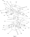
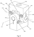
- Figure 4 shows an exploded (in perspective) view of a cardan joint 400 with improved backlash control.
- the adjustment mechanisms are mounted within the yokes of the coupling units rather than in the linkage.
- the joint 400 comprises a first coupling unit 403 which comprises a base 402 and yoke 405.
- the base 402 includes an aperture 404 suitable for attachment to a rotating shaft or other mechanical linkage.
- the yoke 405 includes first and second apertures 406 and 407.
- the coupling unit 403 is identical to the coupling units shown in Figures 1 - 3 .
- the apertures of coupling unit 403 each include respective slots 408. A width of the slots may be adjusted by adjustment screws 409.
- a pair of shafts 410 and 412 are disposed within respective apertures 406 and 407 of the yoke 405. Therefore, by adjustment of the screws 409, the degree of backlash present between the apertures of the yoke and the shafts can be adjusted.
- a second coupling unit 424 comprises a base 425 and yoke 423.
- the second coupling unit 424 is substantially identical to the first coupling unit 403.
- the base 425 includes an aperture 426 suitable for attachment to a rotating shaft or other mechanical linkage.
- the yoke 423 includes first and second apertures 422 and 421.
- the apertures of coupling unit 424 include respective slots 428.
- a width of the slots 428 may be adjusted by adjustment screws 430.
- a pair of shafts 419 and 420 are disposed within respective apertures 422 and 421 of the yoke 423. Therefore, by adjustment of the screws 430, the degree of backlash present between the apertures of the yoke and the shafts can be adjusted.
- the length of the shafts is such that the shafts extend beyond respective apertures 422 and 421 into corresponding apertures 415 of the linkage 413.
- the apertures of the linkage may contain a thread, and the shafts may have a corresponding thread such that they threadedly engage to fix the shafts in place relative to the linkage 413. Therefore the shafts may not rotate relative to the linkage 413, but instead rotate relative to the yoke 423.
- the adjustment mechanism in the example 400 is disposed within respective yokes 405 and 423.
- the shafts shown in the Figures are treated by the application of, for example, a helix tread or similar to thereby increase the surface area and as a result increase the stiffness and static load of the joint.
- untreated shafts may also be used.
- the slots as discussed above may include an elastic element disposed therein, such that theslots are biased to a rest position.
Landscapes
- Engineering & Computer Science (AREA)
- General Engineering & Computer Science (AREA)
- Mechanical Engineering (AREA)
- Pivots And Pivotal Connections (AREA)
Claims (15)
- Kardangelenk (100), das Folgendes umfasst:eine erste Gabel (105); undeine zweite Gabel (126);wobei die erste Gabel (105) und die zweite Gabel (126) über ein Verbindungsglied (111) verbunden sind;wobei das Kardangelenk (100) außerdem Folgendes umfasst:einen Spieleinstellungsmechanismus, wobei der
Spieleinstellungsmechanismus ausgelegt ist, um ein Spiel zwischen dem Verbindungsglied (111) und entweder der ersten Gabel (105) oder der zweiten Gabel (126) zu verringern oder zu erhöhen; undeine Welle (108, 120), die entweder:an einer der Gabeln (105, 126) befestigt ist und mit dem Verbindungsglied (111) in Schraubeingriff steht; oderan dem Verbindungsglied (111) befestigt ist und mit einer der Gabeln (105, 126) in Schraubeingriff steht;um dadurch eine Axialverschiebung zwischen diesen zu verhindern,dadurch gekennzeichnet, dass der oder jeder Spieleinstellungsmechanismus als ein oder mehrere Schlitze (118, 121) innerhalb des Verbindungsglieds (111) bereitgestellt ist, wobei eine Breite des oder jedes Schlitzes (118, 121) einstellbar ist. - Kardangelenk (100) nach Anspruch 1, wobei die erste Gabel (105) oder die zweite Gabel (126) ausgelegt ist, um sich um eine Drehachse des Verbindungsglieds (111) zu drehen und wobei der Spieleinstellungsmechanismus ausgelegt ist, um das Ausmaß des Spiels in einer Achse quer zu der Drehachse zu verringern oder zu erhöhen.
- Kardangelenk (100) nach Anspruch 1 oder Anspruch 2,
wobei der Spieleinstellungsmechanismus ausgelegt ist, um ein Ausmaß des Spiels zwischen dem Verbindungsglied (111) und der ersten Gabel (105) zu verringern oder zu erhöhen, und
das Gelenk (100) außerdem folgendes umfasst:
einen zweiten Spieleinstellungsmechanismus, wobei der zweite Spieleinstellungsmechanismus ausgelegt ist, um einen Grad des Spiels zwischen dem Verbindungsglied (111) und der zweiten Gabel (126) zu verringern oder zu erhöhen. - Kardangelenk (100) nach Anspruch 1, wobei die Welle (108, 120) eine erste Welle (108) ist, die an der ersten Gabel (105) oder der zweiten Gabel (126) befestigt ist und in Bezug auf das Verbindungsglied (111) drehbar ist;
wobei die erste Welle (108) gegebenenfalls innerhalb eines Gehäuses des Verbindungsglieds (111) angeordnet ist und wobei das Einstellen der Breite des Schlitzes (118) eine Abmessung des Gehäuses einstellt. - Kardangelenk (100) nach Anspruch 4, wobei die erste Welle (108) an der ersten Gabel (105) oder der zweiten Gabel (126) durch Muttern oder durch Kleben oder Schweißen befestigt ist.
- Kardangelenk (100) nach einem der vorangegangenen Ansprüche, wobei ein weiterer Spieleinstellungsmechanismus als ein oder mehrere Schlitze innerhalb der ersten Gabel (105) und/oder der zweiten Gabel (126) bereitgestellt ist, wobei eine Breite des oder jedes Schlitzes einstellbar ist.
- Kardangelenk (100) nach Anspruch 6, wobei die Welle eine zweite Welle ist, die an dem Verbindungsglied (111) befestigt ist und in Bezug auf die erste Gabel (105) oder die zweite Gabel (126) drehbar ist;
wobei die zweite Welle gegebenenfalls innerhalb eines Gehäuses der ersten Gabel (105) oder der zweiten Gabel (126) angeordnet ist und wobei das Einstellen der Breite des oder jedes Schlitzes eine Abmessung des Gehäuses einstellt;
und wobei die zweite Welle gegebenenfalls durch Kleben oder Schweißen an dem Verbindungsglied (111) befestigt ist. - Kardangelenk (100) nach einem der vorangegangenen Ansprüche, wobei das Gelenk (100) eine erste Welle (108) und eine zweite Welle (120) umfasst,
wobei die erste Welle (108):an der ersten Gabel (105) befestigt ist und mit dem Verbindungsglied (111) in Schraubeingriff steht; oderan dem Verbindungsglied (111) befestigt ist und mit der ersten Gabel (105) in Schraubeingriff steht;um dadurch eine Axialverschiebung zwischen diesen zu verhindern; und
die zweite Welle (120):an der zweiten Gabel (126) befestigt ist und mit dem Verbindungsglied (111) in Schraubeingriff steht; oderan dem Verbindungsglied (111) befestigt ist und mit der zweiten Gabel (126) in Schraubeingriff steht;um dadurch eine Axialverschiebung zwischen diesen zu verhindern. - Kardangelenk (100) nach einem der vorangegangenen Ansprüche, wobei die Welle bzw. die Wellen (108, 120) und/oder die Gehäuse aus einem Material mit einem niedrigen Reibungskoeffizienten gebildet sind.
- Kardangelenk (100) nach einem der vorangegangenen Ansprüche, wobei der oder jeder Spieleinstellungsmechanismus einen oder mehrere Einstellungsschrauben (119, 122) umfasst, die innerhalb einer Gewindebohrung angeordnet sind.
- Kardangelenk (100) nach einem der vorangegangenen Ansprüche, wobeidie erste Gabel (105) sich in Bezug auf das Verbindungsglied (111) um eine erste Achse dreht,die zweite Gabel (126) sich in Bezug auf das Verbindungsglied (111) um eine zweite Achse dreht; und
die erste Achse und zweite Achse sich kreuzen. - Kardangelenk (100) nach Anspruch 11, wobei das Verbindungsglied (111) Folgendes umfasst:ein quaderförmiges Gehäuse, wobei das Gehäuse vier Öffnungen aufweist, die jeweils auf einer entsprechenden Seite des Gehäuses liegen;wobei vier Wellen jeweils in jeder der vier Öffnungen angeordnet sind und jede Welle an dem Gehäuse befestigt ist.
- Kardangelenk (100) nach einem der Ansprüche 1 bis 12, wobei:das Verbindungsglied (111) sich in Bezug auf die erste Gabel (105) um eine erste Achse dreht,das Verbindungsglied (111) sich in Bezug auf die zweite Gabel (126) um eine zweite Achse dreht; und
die erste und zweite Achse sich nicht kreuzen. - Kardangelenk (100) nach Anspruch 13, wobei das Verbindungsglied (111) Folgendes umfasst:ein quaderförmiges Gehäuse, wobei das Gehäuse zwei Bohrungen aufweist, die sich durch das Gehäuse erstrecken;wobei zwei Wellen jeweils innerhalb der Bohrungen des Verbindungsglieds (111) angeordnet sind und jede Welle (108, 120) an entweder der ersten Gabel (105) oder der zweiten Gabel (126) befestigt ist.
- Mehrachsen-Positionierungsvorrichtung, die ein Kardangelenk (100), wie in einem der Ansprüche 1 bis 14 dargelegt, umfasst.
Applications Claiming Priority (2)
| Application Number | Priority Date | Filing Date | Title |
|---|---|---|---|
| GBGB1706520.2A GB201706520D0 (en) | 2017-04-25 | 2017-04-25 | Cardan joint |
| PCT/EP2018/060387 WO2018197439A1 (en) | 2017-04-25 | 2018-04-23 | Cardan joint |
Publications (3)
| Publication Number | Publication Date |
|---|---|
| EP3615823A1 EP3615823A1 (de) | 2020-03-04 |
| EP3615823B1 true EP3615823B1 (de) | 2021-06-02 |
| EP3615823B8 EP3615823B8 (de) | 2021-07-14 |
Family
ID=58795657
Family Applications (1)
| Application Number | Title | Priority Date | Filing Date |
|---|---|---|---|
| EP18721314.5A Active EP3615823B8 (de) | 2017-04-25 | 2018-04-23 | Kardangelenk |
Country Status (3)
| Country | Link |
|---|---|
| EP (1) | EP3615823B8 (de) |
| GB (1) | GB201706520D0 (de) |
| WO (1) | WO2018197439A1 (de) |
Families Citing this family (1)
| Publication number | Priority date | Publication date | Assignee | Title |
|---|---|---|---|---|
| US20230151846A1 (en) * | 2021-11-15 | 2023-05-18 | Sofec, Inc. | Couplers and mechanical joint assemblies including same |
Family Cites Families (4)
| Publication number | Priority date | Publication date | Assignee | Title |
|---|---|---|---|---|
| US1424299A (en) * | 1921-03-10 | 1922-08-01 | H S & S Mfg Co | Universal joint |
| US1583184A (en) * | 1925-08-15 | 1926-05-04 | Swan A Sandberg | Universal joint |
| US6454657B1 (en) * | 1998-12-31 | 2002-09-24 | Spicer Driveshaft, Inc. | End yoke for a universal joint assembly |
| AU6353101A (en) * | 2000-06-07 | 2001-12-17 | Mathys Johannes Louw | Universal joint |
-
2017
- 2017-04-25 GB GBGB1706520.2A patent/GB201706520D0/en not_active Ceased
-
2018
- 2018-04-23 EP EP18721314.5A patent/EP3615823B8/de active Active
- 2018-04-23 WO PCT/EP2018/060387 patent/WO2018197439A1/en not_active Ceased
Also Published As
| Publication number | Publication date |
|---|---|
| EP3615823A1 (de) | 2020-03-04 |
| EP3615823B8 (de) | 2021-07-14 |
| WO2018197439A1 (en) | 2018-11-01 |
| GB201706520D0 (en) | 2017-06-07 |
Similar Documents
| Publication | Publication Date | Title |
|---|---|---|
| KR102346469B1 (ko) | 물리 치료용 액추에이터 | |
| CN106133395B (zh) | 平行连杆机构和连杆操动装置 | |
| US8291782B1 (en) | Actuator assembly for stabilizers | |
| CN101120181B (zh) | 可变刚度的挠性接头 | |
| JP6609536B2 (ja) | 一体式レンズマウント | |
| EP0790924B1 (de) | Blattwinkel-einstellaufbau für lagerlose rotoren | |
| CN106363662B (zh) | 平面挠曲元件和使用它们的致动器 | |
| US8033197B2 (en) | Fully floating, self-aligning, self-adjusting gimbal assembly for an active human machine interface | |
| US10343709B2 (en) | Restoring torque generating devices | |
| EP3816477B1 (de) | Verbindungsbetätigungsvorrichtung | |
| CN108463651B (zh) | 连杆促动装置 | |
| CN101389873B (zh) | 行星辊式减速机 | |
| JP5535396B2 (ja) | リニアアクチュエータ | |
| US10988162B2 (en) | Steering column assemblies | |
| EP3615823B1 (de) | Kardangelenk | |
| JP6205054B2 (ja) | 工具研削盤のスピンドル | |
| JPH04233507A (ja) | 回転カップリング装置 | |
| JPH0475403B2 (de) | ||
| JP6396078B2 (ja) | パラレルリンク機構およびリンク作動装置 | |
| JP6216410B2 (ja) | シャフトカップリングアセンブリ並びにシャフトカップリングアセンブリによって二つのシャフトを連結する方法及び保守方法 | |
| WO1993009358A1 (en) | Shaft coupling | |
| JP6352054B2 (ja) | パラレルリンク機構およびリンク作動装置 | |
| JP2020143693A (ja) | 直動アクチュエータ | |
| JPS58193931A (ja) | 可撓軸継手 | |
| JP7284978B2 (ja) | 関節機構 |
Legal Events
| Date | Code | Title | Description |
|---|---|---|---|
| STAA | Information on the status of an ep patent application or granted ep patent |
Free format text: STATUS: UNKNOWN |
|
| STAA | Information on the status of an ep patent application or granted ep patent |
Free format text: STATUS: THE INTERNATIONAL PUBLICATION HAS BEEN MADE |
|
| PUAI | Public reference made under article 153(3) epc to a published international application that has entered the european phase |
Free format text: ORIGINAL CODE: 0009012 |
|
| STAA | Information on the status of an ep patent application or granted ep patent |
Free format text: STATUS: REQUEST FOR EXAMINATION WAS MADE |
|
| 17P | Request for examination filed |
Effective date: 20190930 |
|
| AK | Designated contracting states |
Kind code of ref document: A1 Designated state(s): AL AT BE BG CH CY CZ DE DK EE ES FI FR GB GR HR HU IE IS IT LI LT LU LV MC MK MT NL NO PL PT RO RS SE SI SK SM TR |
|
| AX | Request for extension of the european patent |
Extension state: BA ME |
|
| DAV | Request for validation of the european patent (deleted) | ||
| DAX | Request for extension of the european patent (deleted) | ||
| GRAP | Despatch of communication of intention to grant a patent |
Free format text: ORIGINAL CODE: EPIDOSNIGR1 |
|
| STAA | Information on the status of an ep patent application or granted ep patent |
Free format text: STATUS: GRANT OF PATENT IS INTENDED |
|
| INTG | Intention to grant announced |
Effective date: 20201223 |
|
| GRAS | Grant fee paid |
Free format text: ORIGINAL CODE: EPIDOSNIGR3 |
|
| GRAA | (expected) grant |
Free format text: ORIGINAL CODE: 0009210 |
|
| STAA | Information on the status of an ep patent application or granted ep patent |
Free format text: STATUS: THE PATENT HAS BEEN GRANTED |
|
| REG | Reference to a national code |
Ref country code: CH Ref legal event code: EP |
|
| AK | Designated contracting states |
Kind code of ref document: B1 Designated state(s): AL AT BE BG CH CY CZ DE DK EE ES FI FR GB GR HR HU IE IS IT LI LT LU LV MC MK MT NL NO PL PT RO RS SE SI SK SM TR |
|
| REG | Reference to a national code |
Ref country code: GB Ref legal event code: FG4D |
|
| REG | Reference to a national code |
Ref country code: DE Ref legal event code: R081 Ref document number: 602018018053 Country of ref document: DE Owner name: JOZEF STEFAN INSTITUTE, SI Free format text: FORMER OWNERS: JOZEF STEFAN INSTITUTE, LJUBLJANA, SI; KOVAC, IGOR, DR., RADOMLJE, SI Ref country code: DE Ref legal event code: R081 Ref document number: 602018018053 Country of ref document: DE Owner name: FLEX HEX APS, DK Free format text: FORMER OWNERS: JOZEF STEFAN INSTITUTE, LJUBLJANA, SI; KOVAC, IGOR, DR., RADOMLJE, SI |
|
| REG | Reference to a national code |
Ref country code: AT Ref legal event code: REF Ref document number: 1398727 Country of ref document: AT Kind code of ref document: T Effective date: 20210615 |
|
| REG | Reference to a national code |
Ref country code: IE Ref legal event code: FG4D |
|
| REG | Reference to a national code |
Ref country code: DE Ref legal event code: R096 Ref document number: 602018018053 Country of ref document: DE |
|
| REG | Reference to a national code |
Ref country code: CH Ref legal event code: PK Free format text: BERICHTIGUNG B8 |
|
| RAP2 | Party data changed (patent owner data changed or rights of a patent transferred) |
Owner name: FLEX HEX APS Owner name: JOZEF STEFAN INSTITUTE |
|
| REG | Reference to a national code |
Ref country code: LT Ref legal event code: MG9D |
|
| PG25 | Lapsed in a contracting state [announced via postgrant information from national office to epo] |
Ref country code: FI Free format text: LAPSE BECAUSE OF FAILURE TO SUBMIT A TRANSLATION OF THE DESCRIPTION OR TO PAY THE FEE WITHIN THE PRESCRIBED TIME-LIMIT Effective date: 20210602 Ref country code: HR Free format text: LAPSE BECAUSE OF FAILURE TO SUBMIT A TRANSLATION OF THE DESCRIPTION OR TO PAY THE FEE WITHIN THE PRESCRIBED TIME-LIMIT Effective date: 20210602 Ref country code: LT Free format text: LAPSE BECAUSE OF FAILURE TO SUBMIT A TRANSLATION OF THE DESCRIPTION OR TO PAY THE FEE WITHIN THE PRESCRIBED TIME-LIMIT Effective date: 20210602 Ref country code: BG Free format text: LAPSE BECAUSE OF FAILURE TO SUBMIT A TRANSLATION OF THE DESCRIPTION OR TO PAY THE FEE WITHIN THE PRESCRIBED TIME-LIMIT Effective date: 20210902 |
|
| REG | Reference to a national code |
Ref country code: NL Ref legal event code: MP Effective date: 20210602 |
|
| REG | Reference to a national code |
Ref country code: AT Ref legal event code: MK05 Ref document number: 1398727 Country of ref document: AT Kind code of ref document: T Effective date: 20210602 |
|
| PG25 | Lapsed in a contracting state [announced via postgrant information from national office to epo] |
Ref country code: GR Free format text: LAPSE BECAUSE OF FAILURE TO SUBMIT A TRANSLATION OF THE DESCRIPTION OR TO PAY THE FEE WITHIN THE PRESCRIBED TIME-LIMIT Effective date: 20210903 Ref country code: SE Free format text: LAPSE BECAUSE OF FAILURE TO SUBMIT A TRANSLATION OF THE DESCRIPTION OR TO PAY THE FEE WITHIN THE PRESCRIBED TIME-LIMIT Effective date: 20210602 Ref country code: RS Free format text: LAPSE BECAUSE OF FAILURE TO SUBMIT A TRANSLATION OF THE DESCRIPTION OR TO PAY THE FEE WITHIN THE PRESCRIBED TIME-LIMIT Effective date: 20210602 Ref country code: LV Free format text: LAPSE BECAUSE OF FAILURE TO SUBMIT A TRANSLATION OF THE DESCRIPTION OR TO PAY THE FEE WITHIN THE PRESCRIBED TIME-LIMIT Effective date: 20210602 Ref country code: PL Free format text: LAPSE BECAUSE OF FAILURE TO SUBMIT A TRANSLATION OF THE DESCRIPTION OR TO PAY THE FEE WITHIN THE PRESCRIBED TIME-LIMIT Effective date: 20210602 Ref country code: NO Free format text: LAPSE BECAUSE OF FAILURE TO SUBMIT A TRANSLATION OF THE DESCRIPTION OR TO PAY THE FEE WITHIN THE PRESCRIBED TIME-LIMIT Effective date: 20210902 |
|
| PG25 | Lapsed in a contracting state [announced via postgrant information from national office to epo] |
Ref country code: SM Free format text: LAPSE BECAUSE OF FAILURE TO SUBMIT A TRANSLATION OF THE DESCRIPTION OR TO PAY THE FEE WITHIN THE PRESCRIBED TIME-LIMIT Effective date: 20210602 Ref country code: NL Free format text: LAPSE BECAUSE OF FAILURE TO SUBMIT A TRANSLATION OF THE DESCRIPTION OR TO PAY THE FEE WITHIN THE PRESCRIBED TIME-LIMIT Effective date: 20210602 Ref country code: PT Free format text: LAPSE BECAUSE OF FAILURE TO SUBMIT A TRANSLATION OF THE DESCRIPTION OR TO PAY THE FEE WITHIN THE PRESCRIBED TIME-LIMIT Effective date: 20211004 Ref country code: RO Free format text: LAPSE BECAUSE OF FAILURE TO SUBMIT A TRANSLATION OF THE DESCRIPTION OR TO PAY THE FEE WITHIN THE PRESCRIBED TIME-LIMIT Effective date: 20210602 Ref country code: AT Free format text: LAPSE BECAUSE OF FAILURE TO SUBMIT A TRANSLATION OF THE DESCRIPTION OR TO PAY THE FEE WITHIN THE PRESCRIBED TIME-LIMIT Effective date: 20210602 Ref country code: CZ Free format text: LAPSE BECAUSE OF FAILURE TO SUBMIT A TRANSLATION OF THE DESCRIPTION OR TO PAY THE FEE WITHIN THE PRESCRIBED TIME-LIMIT Effective date: 20210602 Ref country code: SK Free format text: LAPSE BECAUSE OF FAILURE TO SUBMIT A TRANSLATION OF THE DESCRIPTION OR TO PAY THE FEE WITHIN THE PRESCRIBED TIME-LIMIT Effective date: 20210602 Ref country code: EE Free format text: LAPSE BECAUSE OF FAILURE TO SUBMIT A TRANSLATION OF THE DESCRIPTION OR TO PAY THE FEE WITHIN THE PRESCRIBED TIME-LIMIT Effective date: 20210602 Ref country code: ES Free format text: LAPSE BECAUSE OF FAILURE TO SUBMIT A TRANSLATION OF THE DESCRIPTION OR TO PAY THE FEE WITHIN THE PRESCRIBED TIME-LIMIT Effective date: 20210602 |
|
| REG | Reference to a national code |
Ref country code: DE Ref legal event code: R097 Ref document number: 602018018053 Country of ref document: DE |
|
| PLBE | No opposition filed within time limit |
Free format text: ORIGINAL CODE: 0009261 |
|
| STAA | Information on the status of an ep patent application or granted ep patent |
Free format text: STATUS: NO OPPOSITION FILED WITHIN TIME LIMIT |
|
| PG25 | Lapsed in a contracting state [announced via postgrant information from national office to epo] |
Ref country code: DK Free format text: LAPSE BECAUSE OF FAILURE TO SUBMIT A TRANSLATION OF THE DESCRIPTION OR TO PAY THE FEE WITHIN THE PRESCRIBED TIME-LIMIT Effective date: 20210602 |
|
| 26N | No opposition filed |
Effective date: 20220303 |
|
| PG25 | Lapsed in a contracting state [announced via postgrant information from national office to epo] |
Ref country code: AL Free format text: LAPSE BECAUSE OF FAILURE TO SUBMIT A TRANSLATION OF THE DESCRIPTION OR TO PAY THE FEE WITHIN THE PRESCRIBED TIME-LIMIT Effective date: 20210602 |
|
| PG25 | Lapsed in a contracting state [announced via postgrant information from national office to epo] |
Ref country code: IT Free format text: LAPSE BECAUSE OF FAILURE TO SUBMIT A TRANSLATION OF THE DESCRIPTION OR TO PAY THE FEE WITHIN THE PRESCRIBED TIME-LIMIT Effective date: 20210602 |
|
| REG | Reference to a national code |
Ref country code: CH Ref legal event code: PL |
|
| REG | Reference to a national code |
Ref country code: BE Ref legal event code: MM Effective date: 20220430 |
|
| PG25 | Lapsed in a contracting state [announced via postgrant information from national office to epo] |
Ref country code: MC Free format text: LAPSE BECAUSE OF FAILURE TO SUBMIT A TRANSLATION OF THE DESCRIPTION OR TO PAY THE FEE WITHIN THE PRESCRIBED TIME-LIMIT Effective date: 20210602 Ref country code: LU Free format text: LAPSE BECAUSE OF NON-PAYMENT OF DUE FEES Effective date: 20220423 Ref country code: LI Free format text: LAPSE BECAUSE OF NON-PAYMENT OF DUE FEES Effective date: 20220430 Ref country code: CH Free format text: LAPSE BECAUSE OF NON-PAYMENT OF DUE FEES Effective date: 20220430 |
|
| PG25 | Lapsed in a contracting state [announced via postgrant information from national office to epo] |
Ref country code: BE Free format text: LAPSE BECAUSE OF NON-PAYMENT OF DUE FEES Effective date: 20220430 |
|
| PG25 | Lapsed in a contracting state [announced via postgrant information from national office to epo] |
Ref country code: IE Free format text: LAPSE BECAUSE OF NON-PAYMENT OF DUE FEES Effective date: 20220423 |
|
| PGFP | Annual fee paid to national office [announced via postgrant information from national office to epo] |
Ref country code: GB Payment date: 20230427 Year of fee payment: 6 |
|
| PG25 | Lapsed in a contracting state [announced via postgrant information from national office to epo] |
Ref country code: MK Free format text: LAPSE BECAUSE OF FAILURE TO SUBMIT A TRANSLATION OF THE DESCRIPTION OR TO PAY THE FEE WITHIN THE PRESCRIBED TIME-LIMIT Effective date: 20210602 Ref country code: CY Free format text: LAPSE BECAUSE OF FAILURE TO SUBMIT A TRANSLATION OF THE DESCRIPTION OR TO PAY THE FEE WITHIN THE PRESCRIBED TIME-LIMIT Effective date: 20210602 |
|
| PG25 | Lapsed in a contracting state [announced via postgrant information from national office to epo] |
Ref country code: HU Free format text: LAPSE BECAUSE OF FAILURE TO SUBMIT A TRANSLATION OF THE DESCRIPTION OR TO PAY THE FEE WITHIN THE PRESCRIBED TIME-LIMIT; INVALID AB INITIO Effective date: 20180423 |
|
| PG25 | Lapsed in a contracting state [announced via postgrant information from national office to epo] |
Ref country code: MT Free format text: LAPSE BECAUSE OF FAILURE TO SUBMIT A TRANSLATION OF THE DESCRIPTION OR TO PAY THE FEE WITHIN THE PRESCRIBED TIME-LIMIT Effective date: 20210602 |
|
| GBPC | Gb: european patent ceased through non-payment of renewal fee |
Effective date: 20240423 |
|
| PG25 | Lapsed in a contracting state [announced via postgrant information from national office to epo] |
Ref country code: GB Free format text: LAPSE BECAUSE OF NON-PAYMENT OF DUE FEES Effective date: 20240423 |
|
| PG25 | Lapsed in a contracting state [announced via postgrant information from national office to epo] |
Ref country code: GB Free format text: LAPSE BECAUSE OF NON-PAYMENT OF DUE FEES Effective date: 20240423 |
|
| PGFP | Annual fee paid to national office [announced via postgrant information from national office to epo] |
Ref country code: DE Payment date: 20250423 Year of fee payment: 8 |
|
| PG25 | Lapsed in a contracting state [announced via postgrant information from national office to epo] |
Ref country code: TR Free format text: LAPSE BECAUSE OF FAILURE TO SUBMIT A TRANSLATION OF THE DESCRIPTION OR TO PAY THE FEE WITHIN THE PRESCRIBED TIME-LIMIT Effective date: 20210602 |
|
| PGFP | Annual fee paid to national office [announced via postgrant information from national office to epo] |
Ref country code: FR Payment date: 20260319 Year of fee payment: 9 |