EP3616285B1 - Dispositif de compensation de courant de défaut à la terre dans des réseaux de distribution d'énergie - Google Patents
Dispositif de compensation de courant de défaut à la terre dans des réseaux de distribution d'énergie Download PDFInfo
- Publication number
- EP3616285B1 EP3616285B1 EP18727902.1A EP18727902A EP3616285B1 EP 3616285 B1 EP3616285 B1 EP 3616285B1 EP 18727902 A EP18727902 A EP 18727902A EP 3616285 B1 EP3616285 B1 EP 3616285B1
- Authority
- EP
- European Patent Office
- Prior art keywords
- reactance elements
- fault current
- voltage
- neutral
- control
- Prior art date
- Legal status (The legal status is an assumption and is not a legal conclusion. Google has not performed a legal analysis and makes no representation as to the accuracy of the status listed.)
- Active
Links
Images


Classifications
-
- H—ELECTRICITY
- H02—GENERATION; CONVERSION OR DISTRIBUTION OF ELECTRIC POWER
- H02H—EMERGENCY PROTECTIVE CIRCUIT ARRANGEMENTS
- H02H9/00—Emergency protective circuit arrangements for limiting excess current or voltage without disconnection
- H02H9/08—Limitation or suppression of earth fault currents, e.g. Petersen coil
-
- H—ELECTRICITY
- H02—GENERATION; CONVERSION OR DISTRIBUTION OF ELECTRIC POWER
- H02J—ELECTRIC POWER NETWORKS; CIRCUIT ARRANGEMENTS OR SYSTEMS FOR SUPPLYING OR DISTRIBUTING ELECTRIC POWER; SYSTEMS FOR STORING ELECTRIC ENERGY
- H02J3/00—Circuit arrangements for AC mains or AC distribution networks
- H02J3/18—Arrangements for adjusting, eliminating or compensating reactive power in networks
- H02J3/1821—Arrangements for adjusting, eliminating or compensating reactive power in networks using shunt compensators
- H02J3/1828—Arrangements for adjusting, eliminating or compensating reactive power in networks using shunt compensators with stepwise control, e.g. switched capacitor banks
-
- H—ELECTRICITY
- H02—GENERATION; CONVERSION OR DISTRIBUTION OF ELECTRIC POWER
- H02J—ELECTRIC POWER NETWORKS; CIRCUIT ARRANGEMENTS OR SYSTEMS FOR SUPPLYING OR DISTRIBUTING ELECTRIC POWER; SYSTEMS FOR STORING ELECTRIC ENERGY
- H02J3/00—Circuit arrangements for AC mains or AC distribution networks
- H02J3/18—Arrangements for adjusting, eliminating or compensating reactive power in networks
- H02J3/1821—Arrangements for adjusting, eliminating or compensating reactive power in networks using shunt compensators
- H02J3/1835—Arrangements for adjusting, eliminating or compensating reactive power in networks using shunt compensators with stepless control
- H02J3/1864—Arrangements for adjusting, eliminating or compensating reactive power in networks using shunt compensators with stepless control using reactive elements connected in series with semiconductor switches, e.g. static VAR compensators [SVC], thyristor-controlled reactors [TCR] or thyristor-switched capacitors [TSC]
-
- H—ELECTRICITY
- H02—GENERATION; CONVERSION OR DISTRIBUTION OF ELECTRIC POWER
- H02J—ELECTRIC POWER NETWORKS; CIRCUIT ARRANGEMENTS OR SYSTEMS FOR SUPPLYING OR DISTRIBUTING ELECTRIC POWER; SYSTEMS FOR STORING ELECTRIC ENERGY
- H02J3/00—Circuit arrangements for AC mains or AC distribution networks
- H02J3/26—Arrangements for eliminating or reducing asymmetry in polyphase networks
Definitions
- the invention concerns a device for earth fault current compensation, comprising two fast adjustable reactance elements, arranged to compensate for an earth fault current in a power network with a power transformer according to claim 1. Furthermore the invention concerns a method to create a neutral voltage in a power network with a power transformer according to claim 6.
- the long distance transport of energy is accomplished at high voltage, preferably 400kV.
- the energy output to the consumers from the transmission network is carried out via grid exit transformers, which in turn, supply a limited geographical area.
- the distribution is mainly effected at 10-30kV voltage levels. Large industry customers are connected directly to the distribution network, while smaller consumers and households are supplied over yet another transformation to 400/230V.
- Distribution networks Due to their meshed structure, transmission networks have relatively high availability. Distribution networks, however, normally have radial structures, and therefore constitute a weak link in the overall power transmission system. Faults on individual distribution lines may lead to disconnection of large groups of consumers. Distribution line fault protection therefor must not only ensure highest possible public safety and fire protection but at the same time also keep the distribution networks available. At a first glance these two aims look difficult to combine.
- the RCC eliminates the driving voltage in that circuit by superimposing an equal but opposite voltage. This is not just a trivial task, since the exact driving voltage is unknown at the beginning of an earth fault.
- the fault current is determined by the driving voltage at the fault side and the impedance of the fault in series with the source impedance. Conversely, to eliminate the fault current completely, the driving voltage at the fault side must be eliminated.
- the driving voltage at the fault side is made up by the phase-to-earth voltage of the supplying transformer (known, respectively measurable at the substation), plus the load current dependent voltage drop between the supplying transformer and the actual fault side, which could be far out in the grid (unknown).
- the necessary power for the RCC inverter is dependent on voltage level and grid size in terms of capacitive leakage current and damping factor.
- Large cable grids in the urban areas of the world may exceed 1000A capacitive leakage current with an uncompensated residual fault current in the order of 100A or more.
- Expensive inverters, larger than 1MVA, are required to compensate these huge currents.
- the present invention propose a novel, more reliable and more cost efficient arrangement for the compensation of the residual earth fault current.
- the objective of the invention is to solve the above problems and offer a simpler and more robust solution for earth fault current compensation.
- a further objective is to compensate the earth fault current completely and thereby improve safety.
- Yet another objective is to improve the reliability of the compensation device and thereby the reliability of the whole power transmission.
- Finally, to lower the costs for the earth fault current compensation is also an objective of the invention.
- the advantage of the invention is improved safety by a very fast elimination of voltage injection and earth fault current into the fault side. No immediate line disconnection is necessary for this. Therefor the new invention improves not only public safety and fire protection but also supply quality.
- the device is simple to manufacture and offers a low cost upgrade for existing arc suppression coils.
- the method according to the invention improves the reliability of existing compensation devices and thereby also improves the availability of the power supply.
- Figures 1 and 2 show a distribution network with a control and measurement unit 2 for the detection of an earth fault and the control of a fault current compensation device. Furthermore the figures show a power transformer 3, a busbar 4 and a number of outgoing feeders L 1 , L 2 ... L N , each with a line breaker 9 at the busbar 4.
- Electric power transmission is generally effected by means of cyclo symmetrical three phase systems. However, even single and two phase systems (railway) exist. The common ground is that transfer of payload (to the consumers) is driven exclusively by the voltages between the phases. If an error occurs in form of an insulation break down between these phases, the feeder in question and all the consumers behind are disconnected by the line breaker 9.
- the fault current to earth at the actual fault side is determined by other currents to earth (mainly capacitive but also resistive leakage currents) in the galvanically interconnected network.
- the sum of all these currents to earth, including the fault current, is always zero (Kirchhoff's current law). From this follows the conclusion: If one wants to bring the fault current to zero, you must make sure all other currents to earth sum up to zero.
- the purpose of the compensation devices in both figure 1 and 2 is to create this balance by producing a corresponding current between the neutral of the network and earth.
- Figure 1 thereby shows a known device for this compensation, consisting of a Petersen coil 5 with an auxiliary power winding 6 for an inverter 7 to inject the residual fault current, which is not compensated by the Petersen coil.
- An option for back up tripping of the faulty feeder 8 in cause of a malfunction of the compensation device is also shown.
- Figure 2 shows an arrangement for compensation of the complete fault current by two reactance elements according to the invention.
- the control and measurement device 2 continuously monitors the zero sequence admittance (Yo) on the outgoing feeders L 1-N and in the earth connection of the compensation device.
- the actual values are stored in the memory of the device. Upon detection of an earth fault the measurement is repeated. Then the difference between the stored and last value is calculated feeder by feeder.
- the fault is on the feeder which shows a difference (delta Yo) between the two values.
- the difference which also can be seen in the earth connection of the compensation device is used to control the setting of the compensation device.
- figure 1 it is the known arrangement with an inverter, while in figure 2 two adjustable reactance elements according to the invention are used to achieve balance. In both cases a controllable voltage is created between the neutral of the network N and earth E.
- FIG. 3 shows a controllable neutral voltage is required to inhibit the driving voltage at the fault side.
- the compensation device has to create this voltage, which must be adjustable in both amplitude and phase with respect to the voltage system of the suppling power transformer.
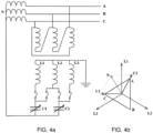
- Figure 4a shows a circuit diagram for the arrangement of two controllable reactance elements according to the invention.
- a reactance element is per definition a passive 2-pole, either capacitive or inductive.
- the reactance elements are made up of two tuneable capacitor banks, already known and used as fast tuning range for different types of fixed Petersen coils.
- Figure 4b finally shows the vector diagram for the compensation arrangement of Figure 4a .
- the delta connected primary winding of the source transformer induces on the wye-connected secondary side three cyclo symmetrical voltages with 120° phase shift.
- the two adjustable reactance elements and the three possible permutations of two of these voltages it is possible to create a resulting voltage which can be varied 0-100% in amplitude and 120° in phase for each permutation, i.e. 360° in total.
- the device can be used for the complete compensation of the earth fault current as well as in parallel to an existing Petersen coil just for the compensation of the residual fault current which is not compensated by the Petersen coil.
Landscapes
- Engineering & Computer Science (AREA)
- Power Engineering (AREA)
- Supply And Distribution Of Alternating Current (AREA)
- Emergency Protection Circuit Devices (AREA)
Claims (8)
- Dispositif comprenant deux éléments à réactance pouvant être commandés (1) agencés pour compenser un courant de défaut monophasé à la terre dans un réseau de distribution d'énergie à transformateur d'alimentation (3), les deux éléments à réactance pouvant être commandés (1) étant chacun connectés avec un premier côté à deux tensions différentes d'une source de tension triphasée qui est synchrone avec le réseau de distribution d'énergie, et en ce que les éléments à réactance sont, avec leur autre côté, connectés conjointement au neutre (N) du réseau de distribution d'énergie, dans lequel les éléments à réactance peuvent être commandés individuellement par une unité de commande (2) conçue pour commander la tension neutre du transformateur d'alimentation (3) par rapport à l'amplitude et la phase en relation avec le propre système de tension du transformateur d'alimentation, caractérisé en ce que lesdits éléments à réactance pouvant être commandés sont constitués de deux batteries de condensateurs ajustables, et dans lequel les deux éléments à réactance peuvent être commandés individuellement pour commander la tension neutre afin d'éliminer la tension d'attaque d'un courant de défaut à la terre.
- Dispositif selon la revendication 1, caractérisé en ce que ladite unité de commande (2) est une unité de commande et de mesure connectée aux éléments à réactance (1) afin de commander une tension secondaire entre le neutre (N) et la terre (E).
- Dispositif selon la revendication 2, caractérisé en ce que l'unité de commande (2) est configurée pour sélectionner les phases à connecter aux éléments à réactance qui à leur tour sont connectés entre le neutre (N) et la terre (E).
- Dispositif selon la revendication 2 ou 3, caractérisé en ce que l'unité de commande (2) est configurée pour commander la taille des éléments à réactance jusqu'à ce que la condition pour une compensation complète d'un courant de défaut à la terre soit remplie.
- Dispositif selon l'une quelconque des revendications 1 à 4, caractérisé en ce que le dispositif est configuré pour fonctionner en parallèle avec une bobine de Petersen afin de compenser le courant de défaut résiduel non compensé par la bobine de Petersen elle-même.
- Procédé de production d'une tension neutre dans un réseau de courant alternatif à transformateur d'alimentation (3), par l'intermédiaire d'un dispositif comprenant deux éléments à réactance pouvant être commandés (1), chacun étant connecté avec un premier côté à deux tensions différentes d'une source de tension triphasée qui est synchrone avec le réseau de distribution d'énergie, et en ce que les éléments à réactance avec leur autre côté sont conjointement connectés au neutre (N) du réseau de distribution d'énergie, dans lequel les éléments à réactance peuvent être commandés individuellement à partir d'une unité de commande (2) configurée pour commander la tension neutre du transformateur d'alimentation (3) par rapport à l'amplitude et à la phase en relation avec le propre système de tension du transformateur d'alimentation, caractérisé en ce que lesdits éléments à réactance pouvant être commandés sont constitués de deux batteries de condensateurs ajustables, et dans lequel le procédé comprend la commande individuelle des deux éléments à réactance afin de commander la tension neutre pour éliminer la tension d'attaque d'un courant de défaut à la terre.
- Utilisation du dispositif selon l'une quelconque des revendications 1 à 5 ou du procédé selon la revendication 6, caractérisée en ce que le but est de compenser un courant de défaut à la terre.
- Utilisation du dispositif selon l'une quelconque des revendications 1 à 5 ou du procédé selon la revendication 6, caractérisée en ce qu'il s'agit d'un fonctionnement en parallèle avec une bobine de Petersen afin de compenser le courant de défaut à la terre résiduel qui n'est pas compensé par la bobine de Petersen elle-même.
Applications Claiming Priority (2)
| Application Number | Priority Date | Filing Date | Title |
|---|---|---|---|
| SE1750651A SE541989C2 (sv) | 2017-05-24 | 2017-05-24 | Anordning och metod för jordfelskompensering i kraftnät |
| PCT/SE2018/050515 WO2018217154A1 (fr) | 2017-05-24 | 2018-05-18 | Dispositif de compensation de courant de défaut à la terre dans des réseaux de distribution d'énergie |
Publications (3)
| Publication Number | Publication Date |
|---|---|
| EP3616285A1 EP3616285A1 (fr) | 2020-03-04 |
| EP3616285C0 EP3616285C0 (fr) | 2023-06-21 |
| EP3616285B1 true EP3616285B1 (fr) | 2023-06-21 |
Family
ID=62386929
Family Applications (1)
| Application Number | Title | Priority Date | Filing Date |
|---|---|---|---|
| EP18727902.1A Active EP3616285B1 (fr) | 2017-05-24 | 2018-05-18 | Dispositif de compensation de courant de défaut à la terre dans des réseaux de distribution d'énergie |
Country Status (7)
| Country | Link |
|---|---|
| US (1) | US11081883B2 (fr) |
| EP (1) | EP3616285B1 (fr) |
| CN (1) | CN110741522B (fr) |
| AU (1) | AU2018273485B2 (fr) |
| RU (1) | RU2758454C2 (fr) |
| SE (1) | SE541989C2 (fr) |
| WO (1) | WO2018217154A1 (fr) |
Families Citing this family (16)
| Publication number | Priority date | Publication date | Assignee | Title |
|---|---|---|---|---|
| CN110571779B (zh) * | 2019-10-18 | 2022-08-26 | 云南电网有限责任公司电力科学研究院 | 一种自产供电源型接地故障补偿系统及故障线的选线方法 |
| CN111193251B (zh) * | 2020-02-06 | 2022-04-05 | 云南电网有限责任公司电力科学研究院 | 一种全补偿系统电压跌落的分析方法 |
| CN111769534B (zh) * | 2020-02-06 | 2022-06-07 | 云南电网有限责任公司电力科学研究院 | 一种电源接地故障电流补偿系统的电压调节方法和装置 |
| CN112117747B (zh) * | 2020-09-24 | 2022-09-27 | 云南电网有限责任公司电力科学研究院 | 一种接地故障电流混合补偿系统及配合方法 |
| CN112054494B (zh) * | 2020-09-24 | 2022-09-27 | 云南电网有限责任公司电力科学研究院 | 一种接地故障电流全补偿系统保护及整定方法 |
| CN112054498B (zh) * | 2020-09-24 | 2022-09-27 | 云南电网有限责任公司电力科学研究院 | 一种接地故障全补偿系统的限流保护方法及装置 |
| CN112269145B (zh) * | 2020-10-14 | 2023-04-07 | 广西电网有限责任公司电力科学研究院 | 一种配电网零电位故障清除方法及系统 |
| CN113113905A (zh) * | 2021-03-22 | 2021-07-13 | 长沙理工大学 | 一种基于对地参数双端测量及闭环控制的配电网消弧方法 |
| CN113036730B (zh) * | 2021-04-19 | 2022-03-08 | 福州大学 | 配电网单相接地故障柔性消弧装置的控制方法 |
| CN113178854B (zh) * | 2021-04-27 | 2023-12-29 | 福州大学 | 一种基于主从控制的配电网接地故障柔性分散消弧方法 |
| CN113904313B (zh) * | 2021-09-30 | 2023-06-23 | 广东电网有限责任公司 | 一种含可控移相器的电力系统的短路电流抑制方法及装置 |
| CN115021203B (zh) * | 2022-06-20 | 2025-10-03 | 广东电网有限责任公司广州供电局 | 接地系统高阻接地保护方法、装置、设备及可读存储介质 |
| FR3139249A1 (fr) * | 2022-08-29 | 2024-03-01 | Electricite De France | Procédé et dispositif de compensation d’un déséquilibre capacitif d’une liaison électrique |
| EP4390411B1 (fr) * | 2022-12-22 | 2025-09-17 | Winter Brothers AB | Système et procédé de localisation de section de défaut à la terre à distance dans des réseaux électriques |
| CN116111603B (zh) * | 2023-03-03 | 2023-06-09 | 湖南大学 | 面向有源配电网的无功电压支撑与故障主动调控复合装置 |
| CN116073396B (zh) * | 2023-03-28 | 2023-06-16 | 湖南大学 | 面向配电网安全优质供电的异质模块混合拓扑方法及系统 |
Family Cites Families (12)
| Publication number | Priority date | Publication date | Assignee | Title |
|---|---|---|---|---|
| SU503368A1 (ru) * | 1973-06-15 | 1976-02-15 | Всесоюзный Научно-Исследовательский Институт Комплексной Автоматизации Мелиорации Систем | Комплексное устройство дл электроснабжени и управлени электрооборудованием |
| SU598171A1 (ru) * | 1976-10-01 | 1978-03-15 | Государственный Институт По Проектированию Лесозаготовительных,Лесосплавных,Деревообрабатывающих Предприятий И Путей Лесотранспорта | Устройство дл компенсации емкостного тока замыкани на землю в сети с изолированной нейтралью с несколькими отход щими лини ми |
| SE437096B (sv) * | 1984-03-12 | 1985-02-04 | Klaus Winter | Anordning for reducering av jordfelsstrommen i icke direktjordade kraftnet |
| SE450675B (sv) * | 1984-11-19 | 1987-07-13 | Klaus Winter | Anordning for overvakning av netparametrarna dempning, osymmetrigrad och snedavstemningsgrad i impedansjordade kraftnet |
| RU2025860C1 (ru) * | 1992-07-07 | 1994-12-30 | Челябинский государственный технический университет | Способ компенсации емкостных токов замыкания на землю |
| DE19525417C2 (de) * | 1995-07-12 | 2000-03-23 | Starkstrom Geraetebau Gmbh | Anordnung zur Erdschluß-Stromkompensation eines mehrphasigen elektrischen Leitungsnetzes |
| CN2438257Y (zh) * | 2000-05-24 | 2001-07-04 | 顺德特种变压器厂 | 自动调谐消弧线圈接地装置 |
| CZ20041055A3 (cs) * | 2004-10-21 | 2005-12-14 | František Ing. Žák | Zapojení pro kompenzaci činné a jalové složky proudu v místě zemního spojení a vyrovnávání fázových napětí v bezporuchovém stavu sítě |
| DE102006021888B3 (de) * | 2006-05-11 | 2007-11-29 | H. Kleinknecht Gmbh & Co. Kg | Anordnung und Verfahren zur Kompensation eines Fehlerstromes bei einem Erdschluss |
| SE537081C2 (sv) * | 2012-08-03 | 2014-12-30 | Swedish Neutral Ab | En anordning innefattande en reglerbar jordningstransformator |
| RU2559809C1 (ru) * | 2014-04-17 | 2015-08-10 | Геннадий Николаевич Марченко | Способ настройки компенсации емкостных токов замыкания на землю |
| CN107276097B (zh) * | 2017-07-05 | 2018-10-09 | 长沙理工大学 | 非有效接地系统接地故障相降压消弧的安全运行方法 |
-
2017
- 2017-05-24 SE SE1750651A patent/SE541989C2/sv unknown
-
2018
- 2018-05-18 WO PCT/SE2018/050515 patent/WO2018217154A1/fr not_active Ceased
- 2018-05-18 RU RU2019137604A patent/RU2758454C2/ru active
- 2018-05-18 EP EP18727902.1A patent/EP3616285B1/fr active Active
- 2018-05-18 CN CN201880034355.9A patent/CN110741522B/zh active Active
- 2018-05-18 US US16/615,970 patent/US11081883B2/en active Active
- 2018-05-18 AU AU2018273485A patent/AU2018273485B2/en active Active
Also Published As
| Publication number | Publication date |
|---|---|
| WO2018217154A1 (fr) | 2018-11-29 |
| AU2018273485B2 (en) | 2022-06-23 |
| US11081883B2 (en) | 2021-08-03 |
| EP3616285C0 (fr) | 2023-06-21 |
| SE1750651A1 (sv) | 2018-11-25 |
| AU2018273485A1 (en) | 2019-12-05 |
| US20200099220A1 (en) | 2020-03-26 |
| EP3616285A1 (fr) | 2020-03-04 |
| BR112019021648A2 (pt) | 2020-05-12 |
| RU2019137604A3 (fr) | 2021-09-27 |
| CN110741522A (zh) | 2020-01-31 |
| RU2758454C2 (ru) | 2021-10-28 |
| SE541989C2 (sv) | 2020-01-14 |
| CN110741522B (zh) | 2021-11-30 |
| RU2019137604A (ru) | 2021-06-24 |
Similar Documents
| Publication | Publication Date | Title |
|---|---|---|
| US11081883B2 (en) | Device for earth fault current compensation in power networks | |
| EP2880732B1 (fr) | Dispositif comprenant un transformateur de mise à la terre contrôlable | |
| JP4927761B2 (ja) | 受動素子を用いた電力線の分散型直列補償システムおよび方法 | |
| EP2118988A1 (fr) | Agencement de transformateur | |
| Cerretti et al. | Temporary overvoltages due to ground faults in MV networks | |
| EP3335289B1 (fr) | Système de compensation de phase | |
| US9257844B2 (en) | Arrangement and method for reactive power compensation | |
| Burstein et al. | Design of a flexible AC/DC-link | |
| Winter | Swedish distribution networks-a new method for earthfault protection in cable-and overhead systems | |
| Varetsky | Overvoltages in MV industrial grid under ground faults | |
| CN113632337B (zh) | 用于具有增加的功率吞吐量的ac电网的方法和系统 | |
| US10680439B2 (en) | Phase compensation system | |
| Sults et al. | Concepts and Practical Application for Distributed Compensation of Earth Fault Current in Latvia's 20 kV Networks | |
| Banerjee et al. | Analysis of the impact on the grounding system in 110 kV grid during bottom-up network restoration | |
| Bucarelli et al. | Investigating the impact of short-circuit faults in different neutral configurations: a real case study | |
| BR112019021648B1 (pt) | Dispositivo para controlar uma tensão neutra, método para produziruma tensão neutra em uma rede de corrente alternada, e, uso do dispositivo | |
| Khorami | Application fields and control principles of variable shunt reactors with tap-changer | |
| Marini | Shunt Reactor Compensation for Subsea Cables in Industrial Plants | |
| Samimi et al. | Reactor failure due to resonance in Zahedan-Iranshahr parallel EHV lines, analysis and practical solutions | |
| Parikh et al. | Challenges and Field Experience on Controlled Switching of EHV Circuit Breakers for Special Applications including Renewable Grid Integration | |
| WO2025237611A1 (fr) | Transformateur de puissance à enroulement tertiaire intégré pour compensation de courant de défaut à la terre | |
| Cinieri | A new lossless circuit balancing the MV distribution systems from insulated shield wires of HV lines | |
| McMILLAN et al. | Integration of an 88 km 220 kV AC cable into the Victorian Electricity Network in Australia | |
| Drozhzhina et al. | Resonant Overvoltages in the 35 kV Compensated Network under Single-Phase Short-Circuit Conditions in the 110 kV Supply Network |
Legal Events
| Date | Code | Title | Description |
|---|---|---|---|
| STAA | Information on the status of an ep patent application or granted ep patent |
Free format text: STATUS: UNKNOWN |
|
| STAA | Information on the status of an ep patent application or granted ep patent |
Free format text: STATUS: THE INTERNATIONAL PUBLICATION HAS BEEN MADE |
|
| PUAI | Public reference made under article 153(3) epc to a published international application that has entered the european phase |
Free format text: ORIGINAL CODE: 0009012 |
|
| STAA | Information on the status of an ep patent application or granted ep patent |
Free format text: STATUS: REQUEST FOR EXAMINATION WAS MADE |
|
| 17P | Request for examination filed |
Effective date: 20191126 |
|
| AK | Designated contracting states |
Kind code of ref document: A1 Designated state(s): AL AT BE BG CH CY CZ DE DK EE ES FI FR GB GR HR HU IE IS IT LI LT LU LV MC MK MT NL NO PL PT RO RS SE SI SK SM TR |
|
| AX | Request for extension of the european patent |
Extension state: BA ME |
|
| RIN1 | Information on inventor provided before grant (corrected) |
Inventor name: WINTER, ANDREAS Inventor name: WINTER, KLAUS Inventor name: WINTER, HAKAN |
|
| RAP1 | Party data changed (applicant data changed or rights of an application transferred) |
Owner name: SWEDISH NEUTRAL AB |
|
| DAV | Request for validation of the european patent (deleted) | ||
| DAX | Request for extension of the european patent (deleted) | ||
| STAA | Information on the status of an ep patent application or granted ep patent |
Free format text: STATUS: EXAMINATION IS IN PROGRESS |
|
| 17Q | First examination report despatched |
Effective date: 20211213 |
|
| GRAP | Despatch of communication of intention to grant a patent |
Free format text: ORIGINAL CODE: EPIDOSNIGR1 |
|
| STAA | Information on the status of an ep patent application or granted ep patent |
Free format text: STATUS: GRANT OF PATENT IS INTENDED |
|
| INTG | Intention to grant announced |
Effective date: 20230307 |
|
| GRAS | Grant fee paid |
Free format text: ORIGINAL CODE: EPIDOSNIGR3 |
|
| RAP1 | Party data changed (applicant data changed or rights of an application transferred) |
Owner name: WINTER BROTHERS AB |
|
| GRAA | (expected) grant |
Free format text: ORIGINAL CODE: 0009210 |
|
| STAA | Information on the status of an ep patent application or granted ep patent |
Free format text: STATUS: THE PATENT HAS BEEN GRANTED |
|
| AK | Designated contracting states |
Kind code of ref document: B1 Designated state(s): AL AT BE BG CH CY CZ DE DK EE ES FI FR GB GR HR HU IE IS IT LI LT LU LV MC MK MT NL NO PL PT RO RS SE SI SK SM TR |
|
| REG | Reference to a national code |
Ref country code: CH Ref legal event code: EP |
|
| REG | Reference to a national code |
Ref country code: DE Ref legal event code: R096 Ref document number: 602018052092 Country of ref document: DE |
|
| REG | Reference to a national code |
Ref country code: AT Ref legal event code: REF Ref document number: 1581610 Country of ref document: AT Kind code of ref document: T Effective date: 20230715 |
|
| REG | Reference to a national code |
Ref country code: IE Ref legal event code: FG4D |
|
| U01 | Request for unitary effect filed |
Effective date: 20230704 |
|
| U07 | Unitary effect registered |
Designated state(s): AT BE BG DE DK EE FI FR IT LT LU LV MT NL PT SE SI Effective date: 20230711 |
|
| REG | Reference to a national code |
Ref country code: LT Ref legal event code: MG9D |
|
| PG25 | Lapsed in a contracting state [announced via postgrant information from national office to epo] |
Ref country code: NO Free format text: LAPSE BECAUSE OF FAILURE TO SUBMIT A TRANSLATION OF THE DESCRIPTION OR TO PAY THE FEE WITHIN THE PRESCRIBED TIME-LIMIT Effective date: 20230921 |
|
| PG25 | Lapsed in a contracting state [announced via postgrant information from national office to epo] |
Ref country code: RS Free format text: LAPSE BECAUSE OF FAILURE TO SUBMIT A TRANSLATION OF THE DESCRIPTION OR TO PAY THE FEE WITHIN THE PRESCRIBED TIME-LIMIT Effective date: 20230621 Ref country code: HR Free format text: LAPSE BECAUSE OF FAILURE TO SUBMIT A TRANSLATION OF THE DESCRIPTION OR TO PAY THE FEE WITHIN THE PRESCRIBED TIME-LIMIT Effective date: 20230621 Ref country code: GR Free format text: LAPSE BECAUSE OF FAILURE TO SUBMIT A TRANSLATION OF THE DESCRIPTION OR TO PAY THE FEE WITHIN THE PRESCRIBED TIME-LIMIT Effective date: 20230922 |
|
| PG25 | Lapsed in a contracting state [announced via postgrant information from national office to epo] |
Ref country code: SK Free format text: LAPSE BECAUSE OF FAILURE TO SUBMIT A TRANSLATION OF THE DESCRIPTION OR TO PAY THE FEE WITHIN THE PRESCRIBED TIME-LIMIT Effective date: 20230621 |
|
| PG25 | Lapsed in a contracting state [announced via postgrant information from national office to epo] |
Ref country code: ES Free format text: LAPSE BECAUSE OF FAILURE TO SUBMIT A TRANSLATION OF THE DESCRIPTION OR TO PAY THE FEE WITHIN THE PRESCRIBED TIME-LIMIT Effective date: 20230621 |
|
| PG25 | Lapsed in a contracting state [announced via postgrant information from national office to epo] |
Ref country code: IS Free format text: LAPSE BECAUSE OF FAILURE TO SUBMIT A TRANSLATION OF THE DESCRIPTION OR TO PAY THE FEE WITHIN THE PRESCRIBED TIME-LIMIT Effective date: 20231021 |
|
| PG25 | Lapsed in a contracting state [announced via postgrant information from national office to epo] |
Ref country code: SM Free format text: LAPSE BECAUSE OF FAILURE TO SUBMIT A TRANSLATION OF THE DESCRIPTION OR TO PAY THE FEE WITHIN THE PRESCRIBED TIME-LIMIT Effective date: 20230621 Ref country code: SK Free format text: LAPSE BECAUSE OF FAILURE TO SUBMIT A TRANSLATION OF THE DESCRIPTION OR TO PAY THE FEE WITHIN THE PRESCRIBED TIME-LIMIT Effective date: 20230621 Ref country code: RO Free format text: LAPSE BECAUSE OF FAILURE TO SUBMIT A TRANSLATION OF THE DESCRIPTION OR TO PAY THE FEE WITHIN THE PRESCRIBED TIME-LIMIT Effective date: 20230621 Ref country code: IS Free format text: LAPSE BECAUSE OF FAILURE TO SUBMIT A TRANSLATION OF THE DESCRIPTION OR TO PAY THE FEE WITHIN THE PRESCRIBED TIME-LIMIT Effective date: 20231021 Ref country code: ES Free format text: LAPSE BECAUSE OF FAILURE TO SUBMIT A TRANSLATION OF THE DESCRIPTION OR TO PAY THE FEE WITHIN THE PRESCRIBED TIME-LIMIT Effective date: 20230621 Ref country code: CZ Free format text: LAPSE BECAUSE OF FAILURE TO SUBMIT A TRANSLATION OF THE DESCRIPTION OR TO PAY THE FEE WITHIN THE PRESCRIBED TIME-LIMIT Effective date: 20230621 |
|
| PG25 | Lapsed in a contracting state [announced via postgrant information from national office to epo] |
Ref country code: PL Free format text: LAPSE BECAUSE OF FAILURE TO SUBMIT A TRANSLATION OF THE DESCRIPTION OR TO PAY THE FEE WITHIN THE PRESCRIBED TIME-LIMIT Effective date: 20230621 |
|
| REG | Reference to a national code |
Ref country code: DE Ref legal event code: R097 Ref document number: 602018052092 Country of ref document: DE |
|
| PLBE | No opposition filed within time limit |
Free format text: ORIGINAL CODE: 0009261 |
|
| STAA | Information on the status of an ep patent application or granted ep patent |
Free format text: STATUS: NO OPPOSITION FILED WITHIN TIME LIMIT |
|
| 26N | No opposition filed |
Effective date: 20240322 |
|
| U20 | Renewal fee for the european patent with unitary effect paid |
Year of fee payment: 7 Effective date: 20240528 |
|
| REG | Reference to a national code |
Ref country code: CH Ref legal event code: PL |
|
| PG25 | Lapsed in a contracting state [announced via postgrant information from national office to epo] |
Ref country code: MC Free format text: LAPSE BECAUSE OF FAILURE TO SUBMIT A TRANSLATION OF THE DESCRIPTION OR TO PAY THE FEE WITHIN THE PRESCRIBED TIME-LIMIT Effective date: 20230621 |
|
| GBPC | Gb: european patent ceased through non-payment of renewal fee |
Effective date: 20240518 |
|
| PG25 | Lapsed in a contracting state [announced via postgrant information from national office to epo] |
Ref country code: MC Free format text: LAPSE BECAUSE OF FAILURE TO SUBMIT A TRANSLATION OF THE DESCRIPTION OR TO PAY THE FEE WITHIN THE PRESCRIBED TIME-LIMIT Effective date: 20230621 Ref country code: CH Free format text: LAPSE BECAUSE OF NON-PAYMENT OF DUE FEES Effective date: 20240531 |
|
| PG25 | Lapsed in a contracting state [announced via postgrant information from national office to epo] |
Ref country code: IE Free format text: LAPSE BECAUSE OF NON-PAYMENT OF DUE FEES Effective date: 20240518 |
|
| PG25 | Lapsed in a contracting state [announced via postgrant information from national office to epo] |
Ref country code: GB Free format text: LAPSE BECAUSE OF NON-PAYMENT OF DUE FEES Effective date: 20240518 |
|
| U20 | Renewal fee for the european patent with unitary effect paid |
Year of fee payment: 8 Effective date: 20250521 |
|
| PG25 | Lapsed in a contracting state [announced via postgrant information from national office to epo] |
Ref country code: CY Free format text: LAPSE BECAUSE OF FAILURE TO SUBMIT A TRANSLATION OF THE DESCRIPTION OR TO PAY THE FEE WITHIN THE PRESCRIBED TIME-LIMIT; INVALID AB INITIO Effective date: 20180518 |
|
| PG25 | Lapsed in a contracting state [announced via postgrant information from national office to epo] |
Ref country code: HU Free format text: LAPSE BECAUSE OF FAILURE TO SUBMIT A TRANSLATION OF THE DESCRIPTION OR TO PAY THE FEE WITHIN THE PRESCRIBED TIME-LIMIT; INVALID AB INITIO Effective date: 20180518 |