EP3616522B1 - Maschine zur ausbildung von gefüllten lebensmitteln - Google Patents
Maschine zur ausbildung von gefüllten lebensmitteln Download PDFInfo
- Publication number
- EP3616522B1 EP3616522B1 EP18860595.0A EP18860595A EP3616522B1 EP 3616522 B1 EP3616522 B1 EP 3616522B1 EP 18860595 A EP18860595 A EP 18860595A EP 3616522 B1 EP3616522 B1 EP 3616522B1
- Authority
- EP
- European Patent Office
- Prior art keywords
- rotary table
- dough
- pressing
- forming machine
- shaping
- Prior art date
- Legal status (The legal status is an assumption and is not a legal conclusion. Google has not performed a legal analysis and makes no representation as to the accuracy of the status listed.)
- Active
Links
Images





Classifications
-
- A—HUMAN NECESSITIES
- A21—BAKING; EDIBLE DOUGHS
- A21C—MACHINES OR EQUIPMENT FOR MAKING OR PROCESSING DOUGHS; HANDLING BAKED ARTICLES MADE FROM DOUGH
- A21C9/00—Other apparatus for handling dough or dough pieces
- A21C9/04—Apparatus for spreading granular material on, or sweeping or coating the surfaces of, pieces or sheets of dough
-
- A—HUMAN NECESSITIES
- A21—BAKING; EDIBLE DOUGHS
- A21C—MACHINES OR EQUIPMENT FOR MAKING OR PROCESSING DOUGHS; HANDLING BAKED ARTICLES MADE FROM DOUGH
- A21C9/00—Other apparatus for handling dough or dough pieces
- A21C9/06—Apparatus for filling pieces of dough such as doughnuts
- A21C9/066—Apparatus for filling pieces of dough such as doughnuts using two separate sheets or pieces of dough with filling in between, e.g. crimped at their edges; Ravioli-making machines
-
- A—HUMAN NECESSITIES
- A21—BAKING; EDIBLE DOUGHS
- A21C—MACHINES OR EQUIPMENT FOR MAKING OR PROCESSING DOUGHS; HANDLING BAKED ARTICLES MADE FROM DOUGH
- A21C11/00—Other machines for forming the dough into its final shape before cooking or baking
- A21C11/10—Other machines for forming the dough into its final shape before cooking or baking combined with cutting apparatus
-
- A—HUMAN NECESSITIES
- A21—BAKING; EDIBLE DOUGHS
- A21C—MACHINES OR EQUIPMENT FOR MAKING OR PROCESSING DOUGHS; HANDLING BAKED ARTICLES MADE FROM DOUGH
- A21C3/00—Machines or apparatus for shaping batches of dough before subdivision
- A21C3/10—Machines or apparatus for shaping batches of dough before subdivision combined with dough-dividing apparatus
-
- A—HUMAN NECESSITIES
- A21—BAKING; EDIBLE DOUGHS
- A21C—MACHINES OR EQUIPMENT FOR MAKING OR PROCESSING DOUGHS; HANDLING BAKED ARTICLES MADE FROM DOUGH
- A21C9/00—Other apparatus for handling dough or dough pieces
- A21C9/06—Apparatus for filling pieces of dough such as doughnuts
- A21C9/063—Applying a folding, wrapping, rolling action
-
- A—HUMAN NECESSITIES
- A21—BAKING; EDIBLE DOUGHS
- A21C—MACHINES OR EQUIPMENT FOR MAKING OR PROCESSING DOUGHS; HANDLING BAKED ARTICLES MADE FROM DOUGH
- A21C9/00—Other apparatus for handling dough or dough pieces
- A21C9/08—Depositing, arranging and conveying apparatus for handling pieces, e.g. sheets of dough
-
- A—HUMAN NECESSITIES
- A21—BAKING; EDIBLE DOUGHS
- A21C—MACHINES OR EQUIPMENT FOR MAKING OR PROCESSING DOUGHS; HANDLING BAKED ARTICLES MADE FROM DOUGH
- A21C9/00—Other apparatus for handling dough or dough pieces
- A21C9/08—Depositing, arranging and conveying apparatus for handling pieces, e.g. sheets of dough
- A21C9/088—Folding or bending discrete dough pieces or dough strips
Definitions
- the present application relates to a technical field of food processing, and more particularly to a stuffed food forming machine.
- the volume of the apparatus for forming stuffed food is usually large, especially the dough wrapper processing device. How to miniaturize stuffed food forming machine has been a difficult problem in the field of food processing.
- the Chinese patent application CN200820062031.X (filing date: Jan. 29, 2018, application name "DUMPLING MAKING MACHINE”) disclosed a dumpling making machine which includes a dough wrapper feeding device, a stuffing injection device, a dumpling shaping device, a discharge tailstock and a driving device.
- the dumpling forming device includes a horizontal station rotary table body, a forming mold disposed on the surface of the rotary table body, a dough wrapper feeding apparatus, a dough wrapper receiving station and a stuffing receiving station which are corresponding to the stuffing injection device and are disposed on the rotary table body.
- a jacking device is arranged at a folding station, one side of a dumpling pushing station is provided with a pushing device, and the other side of the dumpling pushing station is provided with the discharge tailstock.
- the mold is flattened, clamped, opened, and unfolded in different stations under the control of a guide rail.
- a Chinese patent application CN201610274834.0 (filing date: Apr. 28, 2016, application name "COMPACT STUFFED FOOD FORMING MACHINE”) disclosed a compact stuffed food forming machine which belongs to the technical field of food processing and in particular to a compact stuffed food forming machine.
- the compact stuffed food forming machine includes a framework and a station rotary table body located on the framework.
- a dough wrapper forming device, a stuffing injection device, a pressing device and a discharge device are respectively disposed around the station rotary table body.
- a wrapper forming station is disposed on the wrapper forming device; a stuffing injection station is disposed on the stuffing injection device; a pressing station is disposed on the pressing device; and a discharging station is disposed on the discharging device.
- a split shaping mold is further disposed on the framework, and the split shaping mold includes a rotary wrapper receiving plate and a molding cup.
- the present application provides a stuffed food forming machine capable of effectively processing the dough and recucling the dough wrapper residues.
- a stuffed food forming machine including: a framework; a rotary table assembly arranged on the framework and defining an opening configured to collect the dough residue; a sending and cutting station; and a stuffing injection station, where at least the sending and cutting station and the stuffing injection station are arranged around the rotary table assembly, and where a distance between an internal side of a shaping mold rotated together with the rotary table assembly and a center of the rotary table assembly is larger than a distance between an internal side of the opening and the center of the rotary table assembly.
- the stuffed food mentioned in the present application may inlude stuffed foods such as dumplings, sweet dumplings, buns, Siu-mai, Custard bun and Wonton.
- the uncut dough is called a dumpling wrapper dough belt. Wrappers cut from the dumpling wrapper dough belt by the cutter are called dough wrappers, and the remaining dough is called dough residue.
- dough residue When a distance between an internal side of the shaping mold and a center of the rotary table assembly is larger than a distance between an internal side of the opening and the center of the rotary table assembly, the dough residue may easily drop into the opening, so as to be collected.
- a sending and cutting part is provided at the sending and cutting station.
- a stuffing injection part is provided at the stuffing injection station.
- the sending and cutting part and the stuffing injection part may adopt conventional structures.
- the sending and cutting station and stuffing injection station are provided around the rotary table assembly while other processing stations may be provided inside the rotary table body or at other positions.
- a pressing and shaping station and a discharge station are arranged in sequence around the rotary table assembly and beside the stuffing injection station. Where a pressing and shaping part is provided at the pressing and shaping station, and a discharge part is provided at the discharge station.
- the pressing and shaping part and the discharge part may adopt conventional structures.
- Step 1 sending and cutting.
- a shaping mold on a rotary table body is arranged below a sending and cutting station.
- a dough wrapper is cut into a specified shape from a dough belt and falls on the shaping mold below.
- a dough residue enters an opening on the rotary table body and is transported downwardly to be collected.
- Step 2 injecting.
- the shaping mold after receiving the dough wrapper is driven by the rotary table body to rotate to a stuffing injection station where the stuffing is injected onto the dough wrapper.
- the method further includes the following steps:
- Step 3 pressing and shaping.
- the shaping mold after injecting is driven by the rotary table body to rotate to a pressing and shaping station where the dough wrapperis pressed and shaped.
- Step 4 discharging.
- the shaping mold after pressing and shaping is driven by the rotary table body to rotate to a discharge station where a final product is discharged.
- the structure of the rotary table assembly is as follows.
- the rotary table assembly includes the rotary table body defining the opening configured to collect the dough residue, and a plurality of the shaping molds evenly distributed on the rotary table body.
- a distance between the internal side of the shaping mold and a center of the rotary table body is larger than a distance between the internal side of the opening and the center of the rotary table body.
- the opening is a through hole penetrating the rotary table body.
- the opening is continuously defined on the rotary table body, namely, there is no break along the opening, which guarantees a continuous collection of the dough residue when the rotary table body is rotating.
- the structure of the opening must be continuously arranged to collect the dough residue while the rotary table body is rotating.
- the opening When the opening is circular, it may be defined at the center of the rotary table body.
- the opening When the opening is annular, it may be defined at the center or a center-outward position of the rotary table body.
- the opening penetrates an upper surface and a lower surface of the rotary table body.
- Relative positions of the shaping molds and the opening are as follows.
- Upper surfaces of the plurality of shaping molds are located above an upper surface of the opening, and the plurality of shaping molds are arranged outside the opening.
- upper surfaces of the plurality of shaping molds are located above an upper surface of the opening, and projections of the plurality of shaping modes in a vertical direction partially or completely falls within the opening.
- a structure of the rotary table body is as follows.
- the rotary table body is rectangular, circular or irregular.
- a rotation sleeve connected with a worm wheel is connected to a bottom of the rotary table body.
- the worm wheel is connected with a worm screw, and the worm screw is connected with a motor.
- a structure of a rail is as follows.
- a base is arranged under the rotary table body.
- a guiding plate is arranged between the base and the rotary table body, and the guilding plate is a cylinder as a whole.
- a first guiding rail is defined on an external surface of the guilding plate, and the first guiding rail cooperates with a first roller on a catch plate on the shaping mold to move the catch plate up and down.
- the guiding plate is a continuous cylinder.
- At least one disconnected portion is defined on the cylinder of the guiding plate.
- the disconnected portion is partly or entirely disconnected.
- the guiding plate may be provided at stations where structures of the shaping molds move up and down. The guiding plate is not needed for stations where height will not be adjusted.
- a second guiding rail is defined on an edge of the base, and the second guiding rail cooperates with a second roller of the molding cup on the shaping mold to move the molding cup up and down.
- the motor drives the rotary table body to rotate the shaping molds which are connected to the rotary table body.
- the dough residue after cutting enters the opening on the rotary table body, so as to be collected.
- a base and a guiding plate which are arranged under the rotary table body are separated from the rotary table body and are static during working.
- a guiding rail is provided on both the base and the guiding plate respectively. Guiding rollers on the shaping molds are guided by the guiding rail to drive a catch plate and the molds to move up and down respectively.
- the working principle of the guiding rail is as follows.
- each shaping mold includes a catch plate connected with a first roller below through a first connecting rod; and a molding cup provided in the catch plate and connected with a second roller below through a second connecting rod. Since the shaping molds are rotated with the rotating disc while the guiding plate and the base remain still, the catch plate moves up and down by the first roller moving along a wave-shaped track in the first guiding rail on the external surface of the guiding plate. The second guiding rail cooperates with the second roller to move the molding cups up and down. As a result, different parts of the shaping molds move up and down at different stations.
- the structure of the sending and cutting part is as follows.
- the sending and cutting part includes a guiding pillar; a cylinder sleeve sleeved on the guiding pillar; a cutter holding plate connected with the cylinder sleeve and connected with an eccentric wheel through a connecting rod, where the eccentric wheel is driven by a motor directly; a cutter mounted under the cutter holding plate; a cutting plate arranged under the cutter; and a cutter hole defined on the cutting plate corresponding to the cutter.
- the cutter hole cooperates with the cutter to cut the dough wrappers.
- the sending and cutting part further includes: two dough wrapper supporters laterally arranged; two dough feeding rollers mounted between the two dough wrapper supporters in sequence and driven directly by a motor; a plurality of auxiliary rollers arranged between the two dough feeding rollers, where the cutting plate is arranged between the plurality of auxiliary rollers and no conveyor belt which is essential to the conventional machines is need; a supporting pillar provided on an external side of each dough wrapper supporter and provided with the guiding pillar on a top end; a groove defined on an external end of each dough wrapper supporter and configured to accommodate a dough belt roller, where the dough belt is wound to rolls by the dough belt rollers which are placed in the grooves; a driven roller provided above the dough feeding roller; and a drive belt connected the two dough feeding rollers to rotate the two dough feeding rollers synchronously.
- the dough belt is driven by the dough feeding rolle to move toward the cutter.
- the motor directly drives the eccentric wheel to rotate, in such a manner the connecting rod is rotated with the eccentric wheel.
- the cutter holding plate is connected with and driven by the connecting rod and the cylinder sleeve to move up and down along the guiding pillar. The cutter moves up and down with the cutter holding plate and cooperates with the cutter hole on the cutting plate to cut the dough wrapper.
- the structure of the stuffing injection part is as follows.
- the stuffing injection part includes a supporting frame; a hopper arranged on the supporting frame; a rotating base arranged on the supporting frame; a rotating valve provided inside the rotating base and driven directly by a motor to rotate; a stuffing inlet tube connecting the hopper and a top end of the rotating base; a stuffing outlet tube connected below the rotating base; a transverse injecting tube arranged on a lateral side of the rotating base; a transverse injecting rod provided inside the transverse injecting tube; a longitude injecting tube provided at an outlet of the stuffing outlet tube; a gear rack driving mechanism driving the longitude injecting tube to move up and down and provided inside the supporting frame; an eccentric wheel driving mechanism driving the transverse injecting rod to move horizontally; a screw conveyor provided inside the hopper; a worm driving mechanism driving the screw conveyor to rotate; a longitude injecting rod provided inside the longitude injecting tube and driven by the gear rack driving mechanism to move up and down inside the longitude injecting tube to push the stuffing downwardly from the outlet of the stuffing outlet
- the working principle of the stuffing injection part is as follows.
- the motor drives the worm driving mechanism to rotate, and the worm driving mechanism drives the screw conveyor inside the hopper to stir stuffing.
- the stuffing is conveyed to the rotating valve after being stirred by the screw conveyor.
- the motor directly drives the rotating valve to rotate by 90 degrees counter-clockwise after the rotating valve is filled with the stuffing.
- the motor drives the eccentric wheel driving mechanism to drive the transverse injecting rod to move horizontally to push the stuffing out from a bottom of the rotating valve and move the stuffing to an outlet of the stuffing outlet tube.
- the motor drives the gear rack driving mechanism to drive the longitude injecting rod to move up and down to push down the stuffing from the outlet of the stuffing outlet tube.
- the motor drives the gear rack driving mechanism to drive the longitude injecting tube to move down to push the stuffing into the dough wrapper.
- the structure of the pressing and shaping part is as follows.
- the pressing and shaping part includes a supporting pillar; a pair of pressing molds fixed on the supporting pillar, where a top of at least one of the pressing molds is connected with a motor; two gears provided on top ends of the pair of pressing molds respectively, where the two gears are engaged with each other; two pressing blocks provided on two bottom ends of the pair of pressing molds respectively, where the two pressing blocks are opposite to each other, and pressing surfaces of the pressing blocks are curved, and one of the pressing blocks is laterally concave, and the other of the pressing blocks is laterally convex; and two semicircle rotating plates where the two gears are provided on respectively, where curved surfaces of the two rotating plates are opposite to each other.
- the working principle of the pressing and shaping part is as follows.
- the motor drives the top of one of the pressing molds to rotate. Since the top ends of the pressing molds are engaged with each other, the top of the other of the pressing molds is driven to rotate, in such a manner the pressing blocks below press each other. Since the pressing surfaces of the pressing blocks are curved, a wave shape is formed at a sealed edge of the dough wrapper when pressing.
- a method for forming the stuffed food includes the following steps:
- the sending motor drives the dough feeding rollers of the sending and cutting part
- the internal motor drives the longitude injecting rod of the stuffing injection part to reciprocate up and down.
- the pressing motor drives the pressing mold of the pressing and shaping part to press and release;
- the above-mentioned motors may be servo motors.
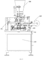
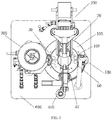
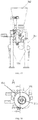
- a stuffed food forming machine which includes a framework 600; a rotary table assembly 100 arranged on the framework 600 and defining an opening 106 configured to collect the dough residue; a sending and cutting station 20; and a stuffing injection station 30. At least the sending and cutting station 20 and the stuffing injection station 30 are arranged around the rotary table assembly 100. A distance between an internal side of a shaping mold 1001 and a center of the rotary table assembly 100 is larger than a distance between an internal side of the opening 106 and the center of the rotary table assembly 100.
- the stuffed food mentioned in the present application may include stuffed foods such as dumplings, sweet dumplings, buns and Siu-mai.
- the uncut dough is called a dumpling wrapper dough belt. Wrappers cut from the dumpling wrapper dough belt by the cutter are called dough wrappers. During the cutting process, the remaining dough is called dough residue.
- dough residue When a distance between an internal side of a shaping mold 1001 and a center of the rotary table assembly 100 is larger than a distance between an internal side of the opening 106 and the center of the rotary table assembly 100, the dough residue may easily drop into the opening 106, so as to be collected.
- a sending and cutting part 200 is provided at the sending and cutting station 20.
- a stuffing injection part 300 is provided at the stuffing injection station 30.
- the sending and cutting part 200 and the stuffing injection part 300 may adopt conventional structures.
- the sending and cutting station 20 and stuffing injection station 30 are provided around the rotary table assembly 100 while other processing stations may be provided inside the rotary table body or at other positions.
- Step 1 sending and cutting.
- a shaping mold 1001 on a rotary table body 101 is arranged below a sending and cutting station 20.
- a dough wrapper is cut into a specified shape from a dough belt and falls on the shaping mold 1001 below.
- a dough residue enters an opening 106 on the rotary table body 101 and is transported downwardly to be collected.
- Step 2 injecting.
- the shaping mold 1001 after receiving the dough wrapper is driven by the rotary table body to rotate to a stuffing injection station 30 where the stuffing is injected onto the dough wrapper.
- a stuffed food forming machine which includes a framework 600; a rotary table assembly 100 arranged on the framework 600 and defining an opening 106 configured to collect the dough residue; a sending and cutting station 20; and a stuffing injection station 30. At least the sending and cutting station 20 and the stuffing injection station 30 are arranged around the rotary table assembly 100. A distance between an internal side of a shaping mold 1001 and a center of the rotary table assembly 100 is larger than a distance between an internal side of the opening 106 and the center of the rotary table assembly 100.
- the stuffed food mentioned in the present application may include stuffed foods such as dumplings, sweet dumplings, buns and Siu-mai.
- the uncut dough is called a dumpling wrapper dough belt. Wrappers cut from the dumpling wrapper dough belt by the cutter are called dough wrappers. During the cutting process, the remaining dough is called dough residue.
- dough residue When a distance between an internal side of a shaping mold 1001 and a center of the rotary table assembly 100 is larger than a distance between an internal side of the opening 106 and the center of the rotary table assembly 100, the dough residue may easily drop into the opening 106, so as to be collected.
- a sending and cutting part 200 is provided at the sending and cutting station 20.
- a stuffing injection part 300 is provided at the stuffing injection station 30.
- the sending and cutting part 200 and the stuffing injection part 300 may adopt conventional structures.
- the sending and cutting station 20 and stuffing injection station 30 are provided around the rotary table assembly 100 while other processing stations may be provided inside the rotary table body or at other positions.
- a pressing and shaping station 40 and a discharge station 50 are arranged in sequence around the rotary table assembly and beside the stuffing injection station 30. Where a pressing and shaping part 400 is provided at the pressing and shaping station 40, and a discharge part 500 is provided at the discharge station 50.
- the pressing and shaping part 400 and the discharge part 500 may adopt conventional structures.
- Step 1 sending and cutting
- a shaping mold 1001 on a rotary table body 101 is arranged below a sending and cutting station 20.
- a dough wrapper is cut into a specified shape from a dough belt and falls on the shaping mold 1001 below.
- a dough residue enters an opening 106 on the rotary table body 101 and is transported downwardly to be collected.
- Step 2 injecting.
- the shaping mold 1001 after receiving the dough wrapper is driven by the rotary table body to rotate to a stuffing injection station 30 where the stuffing is injected onto the dough wrapper.
- the overall working principle may include the following:
- Step 3 pressing and shaping.
- the shaping mold 1001 after injecting is driven by the rotary table body 101 to rotate to a pressing and shaping station 40 where the dough wrapper is pressed and shaped.
- Step 4 discharging.
- the shaping mold 1001 after pressing and shaping is driven by the rotary table body (101) to rotate to a discharge station 50 where a final product is discharged.
- a stuffed food forming machine which includes a framework 600; a rotary table assembly 100 arranged on the framework 600 and defining an opening 106 configured to collect the dough residue; a sending and cutting station 20; and a stuffing injection station 30. At least the sending and cutting station 20 and the stuffing injection station 30 are arranged around the rotary table assembly 100. A distance between an internal side of a shaping mold 1001 and a center of the rotary table assembly 100 is larger than a distance between an internal side of the opening 106 and the center of the rotary table assembly 100.
- the stuffed food mentioned in the present application may include stuffed foods such as dumplings, sweet dumplings, buns and Siu-mai.
- the uncut dough is called a dumpling wrapper dough belt. Wrappers cut from the dumpling wrapper dough belt by the cutter are called dough wrappers. During the cutting process, the remaining dough is called dough residue.
- the dough residue When a distance between an internal side of a shaping mold 1001 and a center of the rotary table assembly 100 is larger than a distance between an internal side of the opening 106 and the center of the rotary table assembly 100, the dough residue may easily drop into the opening 106, so as to be collected.
- a sending and cutting part 200 is provided at the sending and cutting station 20.
- a stuffing injection part 300 is provided at the stuffing injection station 30.
- the sending and cutting part 200 and the stuffing injection part 300 may adopt conventional structures.
- the sending and cutting station 20 and stuffing injection station 30 are provided around the rotary table assembly 100 while other processing stations may be provided inside the rotary table body or at other positions.
- a pressing and shaping station 40 and a discharge station 50 are arranged in sequence around the rotary table assembly and beside the stuffing injection station 30. Where a pressing and shaping part 400 is provided at the pressing and shaping station 40, and a discharge part 500 is provided at the discharge station 50.
- the pressing and shaping part 400 and the discharge part 500 may adopt conventional structures.
- Step 1 sending and cutting
- a shaping mold 1001 on a rotary table body 101 is arranged below a sending and cutting station 20.
- a dough wrapper is cut into a specified shape from a dough belt and falls on the shaping mold 1001 below.
- a dough residue enters an opening 106 on the rotary table body 101 and is transported downwardly to be collected.
- Step 2 injecting.
- the shaping mold 1001 after receiving the dough wrapper is driven by the rotary table body to rotate to a stuffing injection station 30 where the stuffing is injected onto the dough wrapper.
- working principle may include the following:
- Step 3 pressing and shaping.
- the shaping mold 1001 after injecting is driven by the rotary table body 101 to rotate to a pressing and shaping station 40 where the dough wrapper is pressed and shaped.
- Step 4 discharging.
- the shaping mold 1001 after pressing and shaping is driven by the rotary table body to rotate to a discharge station 50 where a final product is discharged.
- a structure of the rotary table assembly 100 is as follows.
- the rotary table assembly 100 includes the rotary table body 101 defining the opening 106 configured to collect the dough residue, and a plurality of the shaping molds 1001 evenly distributed on the rotary table body 101.
- a distance between the internal side of the shaping mold 1001 and a center of the rotary table body 101 is larger than a distance between the internal side of the opening 106 and the center of the rotary table body 101.
- the opening 106 is a through hole penetrating the rotary table body 101.
- the opening 106 is continuously defined on the rotary table body 101, namely, there is no break along the opening, which guarantees a continuous collection of the dough residue when the rotary table body 101 is rotating.
- the structure of the opening 106 must be continuously arranged to collect the dough residue while the rotary table body 101 is rotating.
- the opening 106 When the opening 106 is circular, it may be defined at the center of the rotary table body 101.
- the opening 106 When the opening 106 is annular, it may be defined at the center or a center-outward position of the rotary table body 101.
- the opening 106 may penetrate an upper surface and a lower surface of the rotary table body 101.
- Relative positions of the shaping molds 1001 and the opening 106 are as follows.
- Upper surfaces of the plurality of shaping molds 1001 are located above an upper surface of the opening 106, and the plurality of shaping molds 1001 are arranged outside the opening 106.
- upper surfaces of the plurality of shaping molds 1001 are located above an upper surface of the opening 106, and projections of the plurality of shaping modes 1001 in a vertical direction partially or completely falls within the opening 106.
- a structure of the rotary table body 101 is as follows.
- the rotary table body 101 is rectangular, a circular or an irregular.
- a rotation sleeve 107 connected with a worm wheel 108 is connected to a bottom of the rotary table body 101.
- the worm wheel 108 is connected with a worm screw 109, and the worm screw 109 is connected with a motor.
- a structure of the rail is as follows.
- a base 102 is arranged under the rotary table body 101.
- a guiding plate 103 is arranged between the base 102 and the rotary table body 101, and the guilding plate 103 is a cylinder as a whole.
- a first guiding rail 104 is defined on an external surface of the guilding plate 103, and the first guiding rail 104 cooperates with a first roller 1002 on a catch plate 1004 on the shaping molds 1001 to move the catch plate 1004 up and down.
- the guiding plate 103 is a continuous cylinder.
- At least one disconnected portion is defined on the cylinder of the guiding plate 103.
- the disconnected portion is partly or entirely disconnected.
- the guiding plate 103 may be provided at stations where structures of the shaping molds 1001 move up and down. The guiding plate 103 is not needed for stations where height will not be adjusted.
- a second guiding rail 105 is defined on an edge of the base 102, and the second guiding rail 105 cooperates with a second roller 1003 of the molding cup 1005 on the shaping mold 1001 to move the molding cup 1005 up and down.
- a working principle of the rotary table assembly 100 is as follows.
- the motor drives the rotary table body 101 to rotate the shaping molds 1001 which are connected to the rotary table body 101.
- the dough residue after cutting enters the opening 106 on the rotary table body 101, so as to be collected.
- a base 102 and a guiding plate 103 which are arranged under the rotary table body 101 are separated from the rotary table body and are static during working.
- a guiding rail is provided on both the base 102 and the guiding plate 103 respectively. Guiding rollers on the shaping molds 1001 are guided by the guiding rail to drive the catch plate 1004 and the molds to move up and down respectively.
- a working principle of the rail is as follows.
- each shaping mold 1001 includes a catch plate 1004 connected with a first roller 1002 below through a first connecting rod; and a molding cup 1005 provided in the catch plate 1004 and connected with a second roller 1003 below through a second connecting rod. Since the shaping molds 1001 are rotated with the rotating disc 101 while the guiding plate 103 and the base 102 remain still, the catch plate 1004 moves up and down by the first roller moving along a wave-shaped track in the first guiding rail 104 on the external surface of the guiding plate. The second guiding rail 105 cooperates with the second roller 1003 to move the molding cups 1005 up and down. As a result, different parts of the shaping molds 1001 move up and down at different stations.
- a structure of the sending and cutting part 200 is as follows.
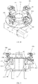
- the sending and cutting part 200 includes a guiding pillar 201; a cylinder sleeve 202 sleeved on the guiding pillar 201; a cutter holding plate 203 connected with the cylinder sleeve 202 and connected with an eccentric wheel 206 through a connecting rod 205, where the eccentric wheel 206 is driven by a motor directly; a cutter 204 mounted under the cutter holding plate 203; a cutting plate 207 is arranged under the cutter 204; and a cutter hole 208 defined on the cutting plate 207 corresponding to the cutter 204.
- the cutter hole 208 cooperates with the cutter 204 to cut the dough wrappers.
- the sending and cutting part 200 further includes two dough wrapper supporters 209 which are laterally arranged; two dough feeding rollers 210 mounted between the two dough wrapper supporters 209 in sequence and driven directly by a motor; a plurality of auxiliary rollers 211 arranged between the two dough feeding rollers 210, where the cutting plate 207 is arranged between the plurality of auxiliary rollers 211 and no conveyor belt which is essential to the conventional machines is needed; a supporting pillar 212 provided on an external side of each dough wrapper supporters 209 and provided with the guiding pillar 201 on a top end; a groove 213 defined on an external end of each dough wrapper supporter 209 and configured to accommodate a dough belt roller, where the dough belt is wound to rolls by the dough belt rollers which are placed in the grooves 213; a driven roller 214 provided above the dough feeding roller 210; and a drive belt 215 connected the two dough feeding rollers to rotate the two dough feeding rollers synchronously.
- a working principle of sending and cutting is as follows.
- the dough belt is driven by the dough feeding rollers 210 to move toward the cutter 204.
- the motor directly drives the eccentric wheel 206 to rotate, in such a manner the connecting rod 205 is rotated with the eccentric wheel 206.
- the cutter holding plate 203 is connected with and driven by the connecting rod 205 and the cylinder sleeve 202 to move up and down along the guiding pillar 201.
- the cutter 204 moves up and down with the cutter holding plate 203 and cooperates with the cutter hole 208 on the cutting plate 207, so as to cut the dough wrapper.
- a structure of the stuffing injection part 300 is as follows.
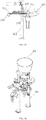
- the stuffing injection part 300 includes a supporting frame 301; a hopper 302 arranged on the supporting frame; a rotating base 303 arranged on the supporting frame; a rotating valve 304 provided inside the rotating base 303 and driven directly by a motor to rotate; a stuffing inlet tube 305 connecting the hopper 302 and a top end of the rotating base 303; a stuffing outlet tube 306 connected below the rotating base 303; a transverse injecting tube 307 arranged on a lateral side of the rotating base 303; a transverse injecting rod 308 provided inside the transverse injecting tube 307; a longitude injecting tube 309 provided at an outlet of the stuffing outlet tube 306; a gear rack driving mechanism 310 driving the longitude injecting tube to move up and down and provided inside the supporting frame 301; an eccentric wheel driving mechanism 311 driving the transverse injecting rod 308 to move horizontally; a screw conveyor 315 provided inside the hopper 302; a worm driving mechanism 312 driving the screw conveyor 315 to rotate;
- a working principle of the stuffing injection part 300 is as follows.
- the motor drives the worm driving mechanism to rotate, and the worm driving mechanism drives the screw conveyor 315 inside the hopper 302 to stir stuffing.
- the stuffing is conveyed to the rotating valve 304 after being stirred by the screw conveyor 315.
- the motor directly drives the rotating valve 304 to rotate by 90 degrees counter-clockwise after the rotating valve 304 is filled with the stuffing.
- the motor drives the eccentric wheel driving mechanism 311 to drive the transverse injecting rod 308 to move horizontally to push the stuffing out from a bottom of the rotating valve 304 and move the stuffing to an outlet of the stuffing outlet tube 306.
- the motor drives the gear rack driving mechanism 310 to drive the longitude injecting rod 313 to move up and down to push down the stuffing from the outlet of the stuffing outlet tube 306.
- the motor drives the gear rack driving mechanism 310 to drive the longitude injecting tube 309 to move down to push the stuffing into the dough wrapper.
- a structure of the pressing and shaping part 400 is as follows.
- the pressing and shaping part 400 includes a supporting pillar 401; a pair of pressing molds 402 fixed on the supporting pillar 401, where a top of at least one of the pressing molds 402 is connected with a motor; two gears 403 provided on top ends of the pair of pressing molds 402 respectively, where the two gear 403 are engaged with each other; two pressing blocks 404 provided on two bottom ends of the pair of pressing molds 402 respectively, where the two pressing block 404 is two, and the two pressing blocks 404 are opposite to each other, and pressing surfaces of the pressing blocks 404 are curved, and one of the pressing blocks 404 is laterally concave, and the other of the pressing blocks 404 is laterally convex; and two semicircle rotating plates 405, where the two gears are provided on respectively, where curved surfaces of the two rotating plates 405 are opposite to each other.
- a working principle of the pressing and shaping part 400 is as follows.
- the motor drives the top of one of the pressing molds 402 to rotate. Since the top ends of the pressing molds 402 are engaged with each other, the top of the other of the pressing molds 402 is driven to rotate, in such a manner the pressing blocks 404 below press each other. Since the pressing surfaces of the pressing blocks 404 are curved, a wave shape is formed at a sealed edge of the dough wrapper when pressing.
- a control method for forming the stuffed food includes the following steps:
- the sending motor drives the dough feeding rollers 210 of the sending and cutting part 200;
- the internal motor drives the longitude injecting rod 313 of the stuffing injection part 300 to reciprocate up and down.
- the pressing motor drives the pressing mold 402 of the pressing and shaping part 400 to press and release;
- the above-mentioned motors may be servo motors.
- the opening 106 on the rotary table assembly 100 collects the dough residue and takes full advantage of the space below the rotary table assembly 100.
- a recycling bin may be provided below the opening 106 to collect the dough residue, or a processing mechanism may be provided below the opening 106 to process the dough residue for reuse.
- the above structure does not increase the size of the machine and requires no extra space.
- the size of present application is compact and is able to be further reduced, which is suitable for family, canteen or small shop.
- the present application replaces the conventional complicated driving mechanism driven by a single motor with separate motors for different parts.
- the opening 106 may be in any shape, as long as it is convenient for collection of the dough residue.
- the distance between an internal side of a shaping mold 1001 and a center of the rotary table body 101 is larger than the distance between an internal side of the opening 106 and the center of the rotary table assembly 100, no matter the shaping molds 1001 are arranged outside the opening 106 or projections of the shaping modes 1001 in a vertical direction partially or completely fall within the structure of the opening 106, the dough residue may conveniently fall into the opening 106 without extra guiding device.
- the present application adopts the motor to drive the worm screw 109 and the worm wheel 108 to drive the rotation sleeve 107 and the rotary table body 101 to rotate.
- the separate driving structure replaces the complicated cam mechanism under the rotary table body 101 and solves the problem of single motor driving all the parts. More space may be used for collection and processing of the dough residue.
- the guiding plate 103 cooperates with the base 102 to move the catch plate 1004 and molding cups 1005 on the shaping mold 1001 up and down at different positions.
- Disconnected portions may be provided on both the first guiding rail 104 on the guiding plate 103 and the second guiding rail 105 on the base 102, namely, the first guiding rail 104 and second guiding rail 105 are only applied to stations where the heights need to be adjusted.
- Non-continuously arranged guiding rails reduce cost in material and are simple in structure.
- the sending and cutting part 200 of the present application omits an internal pushing device inside the cutter 204, a conveyor belt and a scraper.
- the eccentric wheel structure drives the cutter 204 to cut the dough wrappers, which makes the cutting more stable, simplifies the structure and saves space.
- the dough feeding rollers 210 cooperate with the auxiliary rollers 211 to transport the dough belt without the conveyor belt. Furthermore, with the driven roller 214 above the dough feeding rollers 210, more frictions are provided to the dough belt, thereby smoothly moving of the dough belt and avoiding sliding.
- Each part of the present application is driven by an individual driving mechanism and an individual motor, which avoids complicated linkage structures, simplifies the whole structure and reduces the size of the machine.
- the gear rack driving mechanism 310, the eccentric wheel driving mechanism 311 and the worm driving mechanism provide smooth transmission to connected structures, which ensures stability.
- the pressing molds 402 of the present application adopt engaged gears 403 to pressing dough wrapper edges from above.
- the present application improves the conventional structures and prevents squeeze on other part of the dumplings due to the conventional horizontal pressing or pressing from below, so as to maintain appearance of the dumplings.
- the motor drives the pressing molds 402 to rotate directly, which simplifies the structure and ensures the forming effect.
Landscapes
- Life Sciences & Earth Sciences (AREA)
- Engineering & Computer Science (AREA)
- Food Science & Technology (AREA)
- Manufacturing And Processing Devices For Dough (AREA)
- Formation And Processing Of Food Products (AREA)
- Seeds, Soups, And Other Foods (AREA)
Claims (18)
- Formmaschine für gefüllte Lebensmittel, umfassend:eine Drehtischanordnung (100);eine Sende- und Schneidestation (20);und eine Füllinjektionsstation (30),wobei zumindest die Sende- und Schneidstation (20) und die Fülleinspritzstation (30) um die Drehtischanordnung (100) herum angeordnet sind, und dadurch gekennzeichnet, dass die Drehtischanordnung (100) eine Öffnung (106) definiert, die konfiguriert ist, um die Teigreste zu sammeln, wobei ein Abstand zwischen einer Innenseite einer zusammen mit der Drehtischanordnung (100) gedrehten Formgebungsform (1001) und einer Mitte der Drehtischanordnung (100) größer ist als ein Abstand zwischen einer Innenseite der Öffnung (106) und die Mitte der Drehtischanordnung (100).
- Formmaschine für gefüllte Lebensmittel nach Anspruch 1, dadurch gekennzeichnet, dass ein Sende- und Schneideteil (200) an der Sende- und Schneidestation (20) vorgesehen ist, und an der Füllinjektionsstation (30) ein Füllinjektionsteil (300) vorgesehen ist.
- Formmaschine für gefüllte Lebensmittel nach Anspruch 2, dadurch gekennzeichnet, dass eine Press- und Formstation (40) und eine Abführstation (50) nacheinander um die Drehtischanordnung (100) und neben der Fülleinspritzstation (30) angeordnet sind, und wobei ein Press- und Formteil (400) an der Press- und Formstation (40) bereitgestellt wird, und wobei ein Entladeteil (500) an der Entladestation (50) bereitgestellt ist.
- Formmaschine für gefüllte Lebensmittel nach einem der Ansprüche 1 bis 3, dadurch gekennzeichnet, dass die Drehtischanordnung (100) umfasst: einen Drehtischkörper (101), der die Öffnung (106) definiert, die konfiguriert ist, um die Teigreste zu sammeln; und eine Vielzahl der formgebenden Formen (1001) gleichmäßig auf dem Drehtischkörper (101) verteilt, wobei ein Abstand zwischen der Innenseite der Formgebungsform (1001) und einer Mitte des Drehtischkörpers (101) größer ist als ein Abstand zwischen der Innenseite der Öffnung (106) und der Mitte des Drehtischkörpers (101 .). ).
- Formmaschine für gefüllte Lebensmittel nach Anspruch 4, dadurch gekennzeichnet, dass die Öffnung (106) am Drehtischkörper (101) durchgehend definiert ist.
- Formmaschine für gefüllte Lebensmittel nach Anspruch 5, dadurch gekennzeichnet, dass die Öffnung (106) kreisförmig oder ringförmig ist.
- Formmaschine für gefüllte Lebensmittel nach Anspruch 4, dadurch gekennzeichnet, dass die Öffnung (106) so konfiguriert ist, dass sie eine obere Fläche und eine untere Fläche des Drehtischkörpers (101) durchdringt.
- Formmaschine für gefüllte Lebensmittel nach Anspruch 4, dadurch gekennzeichnet, dass obere Oberflächen der Vielzahl von Formgebungsformen (1001) über einer oberen Oberfläche der Öffnung (106) angeordnet sind, und wobei die mehreren Formgebungsformen (1001) außerhalb der Öffnung (106) angeordnet sind.
- Formmaschine für gefüllte Lebensmittel nach Anspruch 4, dadurch gekennzeichnet, dass obere Oberflächen der Vielzahl von Formgebungsformen (1001) über einer oberen Oberfläche der Öffnung (106) angeordnet sind, und Projektionen der Vielzahl von Formgebungsmodi (1001) in einer vertikalen Richtung fallen teilweise oder vollständig in die Öffnung (106).
- Formmaschine für gefüllte Lebensmittel nach Anspruch 4, dadurch gekennzeichnet, dass eine mit einem Schneckenrad (108) verbundene Drehhülse (107) mit einem Boden des Drehtischkörpers (101) verbunden ist, wobei das Schneckenrad (108) mit einer Schneckenschraube (109) verbunden ist und die Schneckenschraube (109) mit einem Motor verbunden ist.
- Formmaschine für gefüllte Lebensmittel nach Anspruch 4, dadurch gekennzeichnet, dass die Drehtischanordnung (100) ferner umfasst: eine Basis (102), die unter dem Drehtischkörper (101) angeordnet ist; eine Führungsplatte (103), die zwischen der Basis (102) und dem Drehtischkörper (101) angeordnet ist, wobei die Führungsplatte (103) insgesamt ein Zylinder ist;eine erste Führungsschiene (104), die auf einer Außenfläche der Führungsplatte (103) definiert ist;Und eine zweite Führungsschiene (105), die an einer Außenkante der Basis (102) definiert ist.
- Formmaschine für gefüllte Lebensmittel nach Anspruch 11, dadurch gekennzeichnet, dass die Führungsplatte (103) ein durchgehender Zylinder ist.
- Formmaschine für gefüllte Lebensmittel nach Anspruch 11, dadurch gekennzeichnet, dass mindestens ein getrennter Abschnitt auf der Führungsplatte (103) definiert ist, und wobei der getrennte Abschnitt teilweise oder vollständig getrennt ist.
- Formmaschine für gefüllte Lebensmittel nach einem der Ansprüche 1 bis 3, dadurch gekennzeichnet, dass der Sende- und Schneideteil (200) umfasst:eine Führungssäule (201);eine Zylinderhülse (202), die auf der Führungssäule (201) aufgesetzt ist;eine Schneidehalteplatte (203), die mit der Zylinderhülse (202) verbunden und mit einem Exzenterrad (206) über eine Pleuelstange (205) verbunden ist;wobei das Exzenterrad (206) direkt von einem Motor angetrieben wird;eine Schneidevorrichtung (204), die unter der Schneidevorrichtungshalteplatte (203) angebracht ist;eine Schneidplatte (207), die unter dem Schneider (204) angeordnet ist; undein Schneideloch (208), das auf der Schneideplatte (207) definiert ist, das dem Schneidegerät (204) entspricht.
- Formmaschine für gefüllte Lebensmittel nach Anspruch 14, dadurch gekennzeichnet, dass der Sende- und Schneideteil (200) ferner umfasst:zwei seitlich angeordnete Teighüllenträger (209);zwei Teigzuführwalzen (210), die nacheinander zwischen den beiden Teighüllenträgern (209) montiert sind und direkt von einem Motor angetrieben werden;eine Vielzahl von Hilfswalzen (211), die zwischen den zwei Teigzuführwalzen (210) angeordnet sind;wobei die Schneidplatte (207) zwischen den mehreren Hilfsrollen (211) angeordnet ist;eine Stützsäule (212), die an einer Außenseite jedes Teighüllenträgers (209) vorgesehen ist und mit der Führungssäule (201) an einem oberen Ende versehen ist;eine angetriebene Walze (214), die über der Teigzuführwalze (210) vorgesehen ist; und einen Antriebsriemen (215), der die beiden Teigzuführwalzen (210) verbindet.
- Formmaschine für gefüllte Lebensmittel nach einem der Ansprüche 1 bis 3, dadurch gekennzeichnet, dass das Fülleinspritzteil (300) umfasst:einen Stützrahmen (301);einen Trichter (302), der auf dem Tragrahmen (301) angeordnet ist;eine drehbare Basis (303), die auf dem Tragrahmen (301) angeordnet ist;ein Drehventil (304), das innerhalb der Drehbasis (303) vorgesehen ist und direkt von einem Motor angetrieben wird, um sich zu drehen;ein Fülleinlassrohr (305), das den Trichter (302) und ein oberes Ende der rotierenden Basis (303) verbindet;ein Füllauslassrohr (306), das unterhalb der rotierenden Basis (303) angeschlossen ist;ein Quereinspritzrohr (307), das an einer seitlichen Seite der rotierenden Basis (303) angeordnet ist;eine Quereinspritzstange (308), die innerhalb des Quereinspritzrohrs (307) vorgesehen ist;ein Längseinspritzrohr (309), das an einem Auslass des Füllauslassrohrs (306) vorgesehen ist;einen Zahnstangenantriebsmechanismus (310), der das Längseinspritzrohr (309) antreibt, um sich nach oben und unten zu bewegen;einen exzentrischen Radantriebsmechanismus (311), der die Quereinspritzstange (308) antreibt, um sich horizontal zu bewegen;einen Schneckenförderer (315), der innerhalb des Trichters (302) vorgesehen ist; undeinen Schneckenantriebsmechanismus (312), der den Schneckenförderer (315) zum Drehen antreibt.
- Formmaschine für gefüllte Lebensmittel nach Anspruch 16, dadurch gekennzeichnet, dass der Fülleinspritzteil (300) ferner umfasst:eine Längseinspritzstange (313), die innerhalb des Längeneinspritzrohrs (309) vorgesehen ist und durch den Zahnstangenantriebsmechanismus (310) angetrieben wird, um sich innerhalb des Längeneinspritzrohrs (309) auf und ab zu bewegen; undeinen L-förmigen Tunnel (314), der innerhalb des Drehventils (304) vorgesehen ist,wobei der Zahnstangenantriebsmechanismus (310), der Exzenterrad Antriebsmechanismus (311) und der Schneckenantriebsmechanismus (312) getrennt durch unterschiedliche Motoren angetrieben werden; undwobei der Zahnstangenantriebsmechanismus (310) innerhalb des Tragrahmens (301) vorgesehen ist.
- Formmaschine für gefüllte Lebensmittel nach einem der Ansprüche 1 bis 3, dadurch gekennzeichnet, dass das Press- und Formteil (400) umfasst:eine Stützsäule (401);ein Paar Pressformen (402), die an der Stützsäule (401) befestigt sind;wobei eine Oberseite von mindestens einer der Pressformen (402) mit einem Motor verbunden ist;zwei Zahnräder (403), die jeweils an den oberen Enden des Paars von Pressformen (402) vorgesehen sind;wobei die zwei Zahnräder (403) miteinander in Eingriff stehen;zwei Preßblöcke (404), die jeweils an zwei unteren Enden des Paars Pressformen (402) vorgesehen sind;wobei die beiden Pressblöcke (404) einander gegenüberliegen;und wobei Pressflächen der Pressblöcke (404) gekrümmt sind; und wobei einer der Druckblöcke (404) seitlich konkav ist und der andere der Druckblöcke (404) seitlich konvex ist;und zwei halbkreisförmige Drehplatten (405), auf denen jeweils die beiden Zahnräder (403) vorgesehen sind, wobei gekrümmte Oberflächen der zwei rotierenden Platten (405) einander gegenüberliegen.
Applications Claiming Priority (2)
| Application Number | Priority Date | Filing Date | Title |
|---|---|---|---|
| CN201710913622.7A CN107410406B (zh) | 2017-09-30 | 2017-09-30 | 包馅食品成型机 |
| PCT/CN2018/078535 WO2019062032A1 (zh) | 2017-09-30 | 2018-03-09 | 包馅食品成型机 |
Publications (3)
| Publication Number | Publication Date |
|---|---|
| EP3616522A1 EP3616522A1 (de) | 2020-03-04 |
| EP3616522A4 EP3616522A4 (de) | 2021-01-06 |
| EP3616522B1 true EP3616522B1 (de) | 2021-09-29 |
Family
ID=60435996
Family Applications (1)
| Application Number | Title | Priority Date | Filing Date |
|---|---|---|---|
| EP18860595.0A Active EP3616522B1 (de) | 2017-09-30 | 2018-03-09 | Maschine zur ausbildung von gefüllten lebensmitteln |
Country Status (5)
| Country | Link |
|---|---|
| US (1) | US11678671B2 (de) |
| EP (1) | EP3616522B1 (de) |
| JP (1) | JP6787615B2 (de) |
| CN (1) | CN107410406B (de) |
| WO (1) | WO2019062032A1 (de) |
Families Citing this family (12)
| Publication number | Priority date | Publication date | Assignee | Title |
|---|---|---|---|---|
| CN107410405B (zh) * | 2017-09-30 | 2018-08-03 | 上海松川远亿机械设备有限公司 | 包馅食品成型机的转盘组件 |
| CN107410406B (zh) * | 2017-09-30 | 2018-08-03 | 上海松川远亿机械设备有限公司 | 包馅食品成型机 |
| CN108552281B (zh) * | 2018-06-26 | 2023-04-28 | 上海三祥澄明冶金材料销售中心(有限合伙) | 一种折云吞机构及其装置及其工作方法 |
| US11406108B1 (en) * | 2019-06-11 | 2022-08-09 | Javier Alatorre | Compact motorized tortilla forming machine |
| CN111528245B (zh) * | 2020-06-15 | 2021-07-27 | 重庆隐涵食品有限公司 | 一种月饼成型设备 |
| CN112936384B (zh) * | 2021-03-04 | 2022-08-26 | 成都松川雷博机械设备有限公司 | 一种馅料分切注入装置 |
| CN113229302A (zh) * | 2021-05-28 | 2021-08-10 | 成都松川雷博机械设备有限公司 | 一种适用于元宝馄饨的包馅食品成型设备及其方法 |
| TWI846036B (zh) * | 2021-09-30 | 2024-06-21 | 日商雷恩自動機股份有限公司 | 包餡食品之成形方法及成形裝置 |
| CN114081050B (zh) * | 2021-12-10 | 2024-10-15 | 胡建谊 | 一种蛋糕自动生产设备 |
| CN115517277B (zh) * | 2022-07-22 | 2023-08-04 | 江南大学 | 馄饨自动裹包、装盒设备及生产方法 |
| CN115251104B (zh) * | 2022-09-28 | 2023-01-10 | 河南晶都笑脸食品有限公司 | 一种可对余料料头裁切的包子输送装置 |
| CN120360114A (zh) * | 2025-06-25 | 2025-07-25 | 诚淘(浙江)机械有限公司 | 一种全自动包饺子机 |
Family Cites Families (24)
| Publication number | Priority date | Publication date | Assignee | Title |
|---|---|---|---|---|
| US1806326A (en) * | 1930-10-21 | 1931-05-19 | Belshaw Walter | Doughnut machine |
| US2574548A (en) * | 1945-07-27 | 1951-11-13 | Alexander T Deutsch | Roll machine |
| US3633517A (en) * | 1970-08-06 | 1972-01-11 | Chung Chin Kao | Automatic egg roll machine |
| JPH10150905A (ja) * | 1996-11-22 | 1998-06-09 | Kajiwara Kogyo Kk | 発酵生地による内材包み込み成形方法およびその装置 |
| JP4521620B2 (ja) * | 2007-08-07 | 2010-08-11 | 東亜工業株式会社 | 餃子の皮の製造装置 |
| CN201160466Y (zh) * | 2008-01-29 | 2008-12-10 | 成都松川雷博机械设备有限公司 | 饺子机 |
| CN201238569Y (zh) * | 2008-08-19 | 2009-05-20 | 成都松川雷博机械设备有限公司 | 回皮机 |
| CN201504540U (zh) * | 2009-08-20 | 2010-06-16 | 通用磨坊销售公司 | 饺子制作设备 |
| CN101991052B (zh) * | 2009-08-20 | 2013-04-24 | 通用磨坊销售公司 | 饺子制作方法及制作设备 |
| KR200457586Y1 (ko) * | 2011-04-27 | 2011-12-26 | 주범식 | 떡 제조기용 성형기 구동장치 |
| US9357788B2 (en) * | 2012-05-29 | 2016-06-07 | Carlos Leon Mesa-Escuderos | Automatic rotary machine for the production of empanadas |
| CN102726671B (zh) * | 2012-06-13 | 2013-08-21 | 朱景超 | 多功能全自动饺子机 |
| CN203801585U (zh) * | 2014-04-25 | 2014-09-03 | 成都松川雷博机械设备有限公司 | 包馅食品成型机 |
| CN204697808U (zh) * | 2015-04-23 | 2015-10-14 | 大连食品机械有限公司 | 用于面点食品的外皮成型机构 |
| JP5839529B1 (ja) * | 2015-04-29 | 2016-01-06 | 株式会社コバード | 封着装置及びそれを備えた包被食品成形装置 |
| US9888693B2 (en) * | 2015-09-03 | 2018-02-13 | Anko Food Machine Co., Ltd. | Dumpling wrapping device |
| EP3207803A1 (de) * | 2016-02-17 | 2017-08-23 | Haas Food Equipment GmbH | Verfahren und vorrichtung zum schneiden der teigausgabe mit einer extrusionsmaschine |
| CN205756906U (zh) * | 2016-04-28 | 2016-12-07 | 成都松川雷博机械设备有限公司 | 直线接皮的紧凑型包馅食品成型机 |
| CN205756904U (zh) * | 2016-04-28 | 2016-12-07 | 成都松川雷博机械设备有限公司 | 紧凑型包馅食品成型机 |
| CN105724507B (zh) * | 2016-04-28 | 2018-09-21 | 成都松川雷博机械设备有限公司 | 紧凑型包馅食品成型机 |
| CN206150320U (zh) * | 2016-11-18 | 2017-05-10 | 河南响当当食品有限公司 | 饺子残皮回收系统 |
| CN106614869B (zh) * | 2016-12-29 | 2022-05-06 | 浙江理工大学 | 全自动饺子生产线 |
| CN206518034U (zh) * | 2017-01-11 | 2017-09-26 | 北京苏稻食品工业有限公司 | 一种包馅机的面皮预处理装置 |
| CN107410406B (zh) * | 2017-09-30 | 2018-08-03 | 上海松川远亿机械设备有限公司 | 包馅食品成型机 |
-
2017
- 2017-09-30 CN CN201710913622.7A patent/CN107410406B/zh active Active
-
2018
- 2018-03-09 EP EP18860595.0A patent/EP3616522B1/de active Active
- 2018-03-09 JP JP2019560701A patent/JP6787615B2/ja active Active
- 2018-03-09 WO PCT/CN2018/078535 patent/WO2019062032A1/zh not_active Ceased
- 2018-03-09 US US16/616,207 patent/US11678671B2/en active Active
Also Published As
| Publication number | Publication date |
|---|---|
| EP3616522A4 (de) | 2021-01-06 |
| US20200205421A1 (en) | 2020-07-02 |
| JP2020518273A (ja) | 2020-06-25 |
| CN107410406B (zh) | 2018-08-03 |
| JP6787615B2 (ja) | 2020-11-18 |
| CN107410406A (zh) | 2017-12-01 |
| EP3616522A1 (de) | 2020-03-04 |
| WO2019062032A1 (zh) | 2019-04-04 |
| US11678671B2 (en) | 2023-06-20 |
Similar Documents
| Publication | Publication Date | Title |
|---|---|---|
| EP3616521B1 (de) | Verfahren zur herstellung von gefüllten lebensmitteln | |
| EP3616522A1 (de) | Maschine zur ausbildung von gefülltem lebensmittel | |
| EP3689144B1 (de) | Drehtischelement für eine maschine zum füllen und wickeln von nahrungsmitteln | |
| CN109964970B (zh) | 一种枣花糕的自动成型设备 | |
| CN116552921B (zh) | 一种中药饮片生产用自动化分装机 | |
| CN113042353B (zh) | 一种中医药制药用草药切断装置 | |
| CN215618279U (zh) | 一种食品加工用面包分块装置 | |
| CN111642589B (zh) | 一种物料压制成型设备 | |
| CN222113523U (zh) | 一种双工位钨粉圆棒压制装置 | |
| CN209768762U (zh) | 饺子成型设备 | |
| CN113083675B (zh) | 一种茶叶分选后碎茶叶的再利用设备 | |
| CN212797394U (zh) | 一种中药颗粒定量调配设备 | |
| CN209920135U (zh) | 一种氮化硅制品塑形工作台 | |
| CN211519959U (zh) | 一种取袋装袋装置 | |
| CN210338437U (zh) | 热熔胶条整理装置 | |
| CN112976116A (zh) | 应用于中药材生产加工的切块机 | |
| CN224170602U (zh) | 一种塑料袋生产用切割装置 | |
| CN217671432U (zh) | 双彩印热封热切电脑制袋机切断机构 | |
| CN118219344B (zh) | 一种泡沫敷料加工裁剪装置 | |
| CN222524148U (zh) | 一种抗生素瓶轧盖装置 | |
| CN217995012U (zh) | 一种制药用精确对版高速滚板式铝塑泡罩包装机 | |
| CN218285888U (zh) | 一种微生物发酵饺子皮用切片装置 | |
| CN215399568U (zh) | 一种一次性杯子用高效自动打包设备 | |
| CN218966061U (zh) | 一种注塑机注塑出料导引机构 | |
| CN222245021U (zh) | 一种中草药切片装置 |
Legal Events
| Date | Code | Title | Description |
|---|---|---|---|
| STAA | Information on the status of an ep patent application or granted ep patent |
Free format text: STATUS: THE INTERNATIONAL PUBLICATION HAS BEEN MADE |
|
| PUAI | Public reference made under article 153(3) epc to a published international application that has entered the european phase |
Free format text: ORIGINAL CODE: 0009012 |
|
| STAA | Information on the status of an ep patent application or granted ep patent |
Free format text: STATUS: REQUEST FOR EXAMINATION WAS MADE |
|
| 17P | Request for examination filed |
Effective date: 20191126 |
|
| AK | Designated contracting states |
Kind code of ref document: A1 Designated state(s): AL AT BE BG CH CY CZ DE DK EE ES FI FR GB GR HR HU IE IS IT LI LT LU LV MC MK MT NL NO PL PT RO RS SE SI SK SM TR |
|
| AX | Request for extension of the european patent |
Extension state: BA ME |
|
| A4 | Supplementary search report drawn up and despatched |
Effective date: 20201204 |
|
| DAV | Request for validation of the european patent (deleted) | ||
| DAX | Request for extension of the european patent (deleted) | ||
| RIC1 | Information provided on ipc code assigned before grant |
Ipc: A21C 9/08 20060101AFI20201130BHEP Ipc: A21C 9/06 20060101ALI20201130BHEP Ipc: A21C 3/10 20060101ALI20201130BHEP Ipc: A21C 11/10 20060101ALI20201130BHEP |
|
| REG | Reference to a national code |
Ref country code: DE Ref legal event code: R079 Ref document number: 602018024443 Country of ref document: DE Free format text: PREVIOUS MAIN CLASS: A21C0009080000 Ipc: A21C0009060000 |
|
| RIC1 | Information provided on ipc code assigned before grant |
Ipc: A21C 11/10 20060101ALI20210303BHEP Ipc: A21C 9/04 20060101ALI20210303BHEP Ipc: A21C 9/06 20060101AFI20210303BHEP Ipc: A21C 3/10 20060101ALI20210303BHEP Ipc: A21C 9/08 20060101ALI20210303BHEP |
|
| GRAP | Despatch of communication of intention to grant a patent |
Free format text: ORIGINAL CODE: EPIDOSNIGR1 |
|
| STAA | Information on the status of an ep patent application or granted ep patent |
Free format text: STATUS: GRANT OF PATENT IS INTENDED |
|
| INTG | Intention to grant announced |
Effective date: 20210531 |
|
| GRAS | Grant fee paid |
Free format text: ORIGINAL CODE: EPIDOSNIGR3 |
|
| GRAA | (expected) grant |
Free format text: ORIGINAL CODE: 0009210 |
|
| STAA | Information on the status of an ep patent application or granted ep patent |
Free format text: STATUS: THE PATENT HAS BEEN GRANTED |
|
| AK | Designated contracting states |
Kind code of ref document: B1 Designated state(s): AL AT BE BG CH CY CZ DE DK EE ES FI FR GB GR HR HU IE IS IT LI LT LU LV MC MK MT NL NO PL PT RO RS SE SI SK SM TR |
|
| REG | Reference to a national code |
Ref country code: GB Ref legal event code: FG4D |
|
| REG | Reference to a national code |
Ref country code: CH Ref legal event code: EP Ref country code: AT Ref legal event code: REF Ref document number: 1433439 Country of ref document: AT Kind code of ref document: T Effective date: 20211015 |
|
| REG | Reference to a national code |
Ref country code: DE Ref legal event code: R096 Ref document number: 602018024443 Country of ref document: DE |
|
| REG | Reference to a national code |
Ref country code: IE Ref legal event code: FG4D |
|
| REG | Reference to a national code |
Ref country code: LT Ref legal event code: MG9D |
|
| PG25 | Lapsed in a contracting state [announced via postgrant information from national office to epo] |
Ref country code: HR Free format text: LAPSE BECAUSE OF FAILURE TO SUBMIT A TRANSLATION OF THE DESCRIPTION OR TO PAY THE FEE WITHIN THE PRESCRIBED TIME-LIMIT Effective date: 20210929 Ref country code: NO Free format text: LAPSE BECAUSE OF FAILURE TO SUBMIT A TRANSLATION OF THE DESCRIPTION OR TO PAY THE FEE WITHIN THE PRESCRIBED TIME-LIMIT Effective date: 20211229 Ref country code: LT Free format text: LAPSE BECAUSE OF FAILURE TO SUBMIT A TRANSLATION OF THE DESCRIPTION OR TO PAY THE FEE WITHIN THE PRESCRIBED TIME-LIMIT Effective date: 20210929 Ref country code: BG Free format text: LAPSE BECAUSE OF FAILURE TO SUBMIT A TRANSLATION OF THE DESCRIPTION OR TO PAY THE FEE WITHIN THE PRESCRIBED TIME-LIMIT Effective date: 20211229 Ref country code: SE Free format text: LAPSE BECAUSE OF FAILURE TO SUBMIT A TRANSLATION OF THE DESCRIPTION OR TO PAY THE FEE WITHIN THE PRESCRIBED TIME-LIMIT Effective date: 20210929 Ref country code: RS Free format text: LAPSE BECAUSE OF FAILURE TO SUBMIT A TRANSLATION OF THE DESCRIPTION OR TO PAY THE FEE WITHIN THE PRESCRIBED TIME-LIMIT Effective date: 20210929 Ref country code: FI Free format text: LAPSE BECAUSE OF FAILURE TO SUBMIT A TRANSLATION OF THE DESCRIPTION OR TO PAY THE FEE WITHIN THE PRESCRIBED TIME-LIMIT Effective date: 20210929 |
|
| REG | Reference to a national code |
Ref country code: NL Ref legal event code: MP Effective date: 20210929 |
|
| REG | Reference to a national code |
Ref country code: AT Ref legal event code: MK05 Ref document number: 1433439 Country of ref document: AT Kind code of ref document: T Effective date: 20210929 |
|
| PG25 | Lapsed in a contracting state [announced via postgrant information from national office to epo] |
Ref country code: LV Free format text: LAPSE BECAUSE OF FAILURE TO SUBMIT A TRANSLATION OF THE DESCRIPTION OR TO PAY THE FEE WITHIN THE PRESCRIBED TIME-LIMIT Effective date: 20210929 Ref country code: GR Free format text: LAPSE BECAUSE OF FAILURE TO SUBMIT A TRANSLATION OF THE DESCRIPTION OR TO PAY THE FEE WITHIN THE PRESCRIBED TIME-LIMIT Effective date: 20211230 |
|
| PG25 | Lapsed in a contracting state [announced via postgrant information from national office to epo] |
Ref country code: AT Free format text: LAPSE BECAUSE OF FAILURE TO SUBMIT A TRANSLATION OF THE DESCRIPTION OR TO PAY THE FEE WITHIN THE PRESCRIBED TIME-LIMIT Effective date: 20210929 |
|
| PG25 | Lapsed in a contracting state [announced via postgrant information from national office to epo] |
Ref country code: IS Free format text: LAPSE BECAUSE OF FAILURE TO SUBMIT A TRANSLATION OF THE DESCRIPTION OR TO PAY THE FEE WITHIN THE PRESCRIBED TIME-LIMIT Effective date: 20220129 Ref country code: SK Free format text: LAPSE BECAUSE OF FAILURE TO SUBMIT A TRANSLATION OF THE DESCRIPTION OR TO PAY THE FEE WITHIN THE PRESCRIBED TIME-LIMIT Effective date: 20210929 Ref country code: RO Free format text: LAPSE BECAUSE OF FAILURE TO SUBMIT A TRANSLATION OF THE DESCRIPTION OR TO PAY THE FEE WITHIN THE PRESCRIBED TIME-LIMIT Effective date: 20210929 Ref country code: PT Free format text: LAPSE BECAUSE OF FAILURE TO SUBMIT A TRANSLATION OF THE DESCRIPTION OR TO PAY THE FEE WITHIN THE PRESCRIBED TIME-LIMIT Effective date: 20220131 Ref country code: PL Free format text: LAPSE BECAUSE OF FAILURE TO SUBMIT A TRANSLATION OF THE DESCRIPTION OR TO PAY THE FEE WITHIN THE PRESCRIBED TIME-LIMIT Effective date: 20210929 Ref country code: NL Free format text: LAPSE BECAUSE OF FAILURE TO SUBMIT A TRANSLATION OF THE DESCRIPTION OR TO PAY THE FEE WITHIN THE PRESCRIBED TIME-LIMIT Effective date: 20210929 Ref country code: ES Free format text: LAPSE BECAUSE OF FAILURE TO SUBMIT A TRANSLATION OF THE DESCRIPTION OR TO PAY THE FEE WITHIN THE PRESCRIBED TIME-LIMIT Effective date: 20210929 Ref country code: EE Free format text: LAPSE BECAUSE OF FAILURE TO SUBMIT A TRANSLATION OF THE DESCRIPTION OR TO PAY THE FEE WITHIN THE PRESCRIBED TIME-LIMIT Effective date: 20210929 Ref country code: CZ Free format text: LAPSE BECAUSE OF FAILURE TO SUBMIT A TRANSLATION OF THE DESCRIPTION OR TO PAY THE FEE WITHIN THE PRESCRIBED TIME-LIMIT Effective date: 20210929 Ref country code: AL Free format text: LAPSE BECAUSE OF FAILURE TO SUBMIT A TRANSLATION OF THE DESCRIPTION OR TO PAY THE FEE WITHIN THE PRESCRIBED TIME-LIMIT Effective date: 20210929 |
|
| REG | Reference to a national code |
Ref country code: DE Ref legal event code: R097 Ref document number: 602018024443 Country of ref document: DE |
|
| PG25 | Lapsed in a contracting state [announced via postgrant information from national office to epo] |
Ref country code: DK Free format text: LAPSE BECAUSE OF FAILURE TO SUBMIT A TRANSLATION OF THE DESCRIPTION OR TO PAY THE FEE WITHIN THE PRESCRIBED TIME-LIMIT Effective date: 20210929 |
|
| PLBE | No opposition filed within time limit |
Free format text: ORIGINAL CODE: 0009261 |
|
| STAA | Information on the status of an ep patent application or granted ep patent |
Free format text: STATUS: NO OPPOSITION FILED WITHIN TIME LIMIT |
|
| 26N | No opposition filed |
Effective date: 20220630 |
|
| PG25 | Lapsed in a contracting state [announced via postgrant information from national office to epo] |
Ref country code: MC Free format text: LAPSE BECAUSE OF FAILURE TO SUBMIT A TRANSLATION OF THE DESCRIPTION OR TO PAY THE FEE WITHIN THE PRESCRIBED TIME-LIMIT Effective date: 20210929 |
|
| REG | Reference to a national code |
Ref country code: CH Ref legal event code: PL |
|
| PG25 | Lapsed in a contracting state [announced via postgrant information from national office to epo] |
Ref country code: SI Free format text: LAPSE BECAUSE OF FAILURE TO SUBMIT A TRANSLATION OF THE DESCRIPTION OR TO PAY THE FEE WITHIN THE PRESCRIBED TIME-LIMIT Effective date: 20210929 |
|
| REG | Reference to a national code |
Ref country code: BE Ref legal event code: MM Effective date: 20220331 |
|
| PG25 | Lapsed in a contracting state [announced via postgrant information from national office to epo] |
Ref country code: LU Free format text: LAPSE BECAUSE OF NON-PAYMENT OF DUE FEES Effective date: 20220309 Ref country code: LI Free format text: LAPSE BECAUSE OF NON-PAYMENT OF DUE FEES Effective date: 20220331 Ref country code: IT Free format text: LAPSE BECAUSE OF FAILURE TO SUBMIT A TRANSLATION OF THE DESCRIPTION OR TO PAY THE FEE WITHIN THE PRESCRIBED TIME-LIMIT Effective date: 20210929 Ref country code: IE Free format text: LAPSE BECAUSE OF NON-PAYMENT OF DUE FEES Effective date: 20220309 Ref country code: CH Free format text: LAPSE BECAUSE OF NON-PAYMENT OF DUE FEES Effective date: 20220331 |
|
| PG25 | Lapsed in a contracting state [announced via postgrant information from national office to epo] |
Ref country code: BE Free format text: LAPSE BECAUSE OF NON-PAYMENT OF DUE FEES Effective date: 20220331 |
|
| PG25 | Lapsed in a contracting state [announced via postgrant information from national office to epo] |
Ref country code: SM Free format text: LAPSE BECAUSE OF FAILURE TO SUBMIT A TRANSLATION OF THE DESCRIPTION OR TO PAY THE FEE WITHIN THE PRESCRIBED TIME-LIMIT Effective date: 20210929 Ref country code: MK Free format text: LAPSE BECAUSE OF FAILURE TO SUBMIT A TRANSLATION OF THE DESCRIPTION OR TO PAY THE FEE WITHIN THE PRESCRIBED TIME-LIMIT Effective date: 20210929 Ref country code: CY Free format text: LAPSE BECAUSE OF FAILURE TO SUBMIT A TRANSLATION OF THE DESCRIPTION OR TO PAY THE FEE WITHIN THE PRESCRIBED TIME-LIMIT Effective date: 20210929 |
|
| PG25 | Lapsed in a contracting state [announced via postgrant information from national office to epo] |
Ref country code: HU Free format text: LAPSE BECAUSE OF FAILURE TO SUBMIT A TRANSLATION OF THE DESCRIPTION OR TO PAY THE FEE WITHIN THE PRESCRIBED TIME-LIMIT; INVALID AB INITIO Effective date: 20180309 |
|
| PG25 | Lapsed in a contracting state [announced via postgrant information from national office to epo] |
Ref country code: MT Free format text: LAPSE BECAUSE OF FAILURE TO SUBMIT A TRANSLATION OF THE DESCRIPTION OR TO PAY THE FEE WITHIN THE PRESCRIBED TIME-LIMIT Effective date: 20210929 |
|
| PG25 | Lapsed in a contracting state [announced via postgrant information from national office to epo] |
Ref country code: TR Free format text: LAPSE BECAUSE OF FAILURE TO SUBMIT A TRANSLATION OF THE DESCRIPTION OR TO PAY THE FEE WITHIN THE PRESCRIBED TIME-LIMIT Effective date: 20210929 |
|
| PGFP | Annual fee paid to national office [announced via postgrant information from national office to epo] |
Ref country code: GB Payment date: 20260318 Year of fee payment: 9 |
|
| PGFP | Annual fee paid to national office [announced via postgrant information from national office to epo] |
Ref country code: DE Payment date: 20260318 Year of fee payment: 9 |
|
| PGFP | Annual fee paid to national office [announced via postgrant information from national office to epo] |
Ref country code: FR Payment date: 20260318 Year of fee payment: 9 |