EP3616772A1 - Procédé de nettoyage de filtres - Google Patents
Procédé de nettoyage de filtres Download PDFInfo
- Publication number
- EP3616772A1 EP3616772A1 EP19194075.8A EP19194075A EP3616772A1 EP 3616772 A1 EP3616772 A1 EP 3616772A1 EP 19194075 A EP19194075 A EP 19194075A EP 3616772 A1 EP3616772 A1 EP 3616772A1
- Authority
- EP
- European Patent Office
- Prior art keywords
- pressure
- cleaning
- filter
- valve
- pressure pulse
- Prior art date
- Legal status (The legal status is an assumption and is not a legal conclusion. Google has not performed a legal analysis and makes no representation as to the accuracy of the status listed.)
- Withdrawn
Links
- 238000004140 cleaning Methods 0.000 title claims abstract description 50
- 238000000034 method Methods 0.000 title claims abstract description 20
- 239000012530 fluid Substances 0.000 claims abstract description 3
- 238000011109 contamination Methods 0.000 claims description 2
- 239000007789 gas Substances 0.000 description 8
- 239000000463 material Substances 0.000 description 3
- 238000010586 diagram Methods 0.000 description 2
- 238000000605 extraction Methods 0.000 description 2
- 239000012065 filter cake Substances 0.000 description 2
- 238000011010 flushing procedure Methods 0.000 description 2
- 239000002245 particle Substances 0.000 description 2
- 238000011001 backwashing Methods 0.000 description 1
- 230000001419 dependent effect Effects 0.000 description 1
- 239000000428 dust Substances 0.000 description 1
- 239000012535 impurity Substances 0.000 description 1
- 239000012528 membrane Substances 0.000 description 1
- 238000001179 sorption measurement Methods 0.000 description 1
- 239000004753 textile Substances 0.000 description 1
Images

Classifications
-
- B—PERFORMING OPERATIONS; TRANSPORTING
- B01—PHYSICAL OR CHEMICAL PROCESSES OR APPARATUS IN GENERAL
- B01D—SEPARATION
- B01D46/00—Filters or filtering processes specially modified for separating dispersed particles from gases or vapours
- B01D46/42—Auxiliary equipment or operation thereof
- B01D46/44—Auxiliary equipment or operation thereof controlling filtration
- B01D46/446—Auxiliary equipment or operation thereof controlling filtration by pressure measuring
-
- B—PERFORMING OPERATIONS; TRANSPORTING
- B01—PHYSICAL OR CHEMICAL PROCESSES OR APPARATUS IN GENERAL
- B01D—SEPARATION
- B01D46/00—Filters or filtering processes specially modified for separating dispersed particles from gases or vapours
- B01D46/66—Regeneration of the filtering material or filter elements inside the filter
- B01D46/70—Regeneration of the filtering material or filter elements inside the filter by acting counter-currently on the filtering surface, e.g. by flushing on the non-cake side of the filter
- B01D46/71—Regeneration of the filtering material or filter elements inside the filter by acting counter-currently on the filtering surface, e.g. by flushing on the non-cake side of the filter with pressurised gas, e.g. pulsed air
Definitions
- the present invention relates to a method for cleaning filters with tubular or bag-shaped filter bodies, which are surrounded by a filter housing, with the following steps: flowing through the filter body with a gaseous fluid to be cleaned in a flow direction and generating a first pressure pulse against the filter bodies the flow direction for cleaning the filter body by briefly opening at least one valve.
- the EP 1 997 547 B1 discloses a method for backwashing filters, in which several extraction lines are connected to a compressed air tank. A valve is provided on each extraction line which can be opened briefly in order to direct the compressed air to a flushing line, through which pressure pulses can then be generated on filter bodies for cleaning the filter bodies. As a result, the filter bodies can be used continuously for exhaust gas cleaning and only rarely have to be replaced.
- de EP 2 602 016 B1 proposed to lower the pressure in the cleaning tank and to enlarge the valve cross sections in order to reduce the flow losses.
- a filter hose is cleaned by a flushing line using pressure pulses.
- the filter body may clog quickly and block up accordingly.
- the filter bodies are cleaned by briefly opening at least one valve or a plurality of valves connected in parallel generates at least one second pressure pulse on the filter bodies against the flow direction for further cleaning of the filter bodies during a cleaning cycle. It has been found that short-term opening of at least one valve or a plurality of valves connected in parallel to generate one or more further pressure pulses improves cleaning. Furthermore, the mechanical pressure on the filter material can be reduced by the additional pressure pulses, since the filter cleaning is distributed over several pressure surges and the mechanical load is reduced when the filter material falls back onto the support body at the end of the cleaning. The lower mechanical load on the filter body also reduces the residual dust in the clean gas.
- the cleaning can also be adapted to different filter systems and dusts.
- the time between two pressure pulses is preferably less than 2 s, in particular less than 1 s.
- a cleaning cycle thus also lasts a maximum of a few seconds, preferably the entire cleaning cycle lasts less than 1 s.
- the opening time of the at least one valve or a plurality of valves connected in parallel for generating a pressure pulse is preferably between 40 and 300 ms, in particular 60 to 150 ms. As a result, the filter body can be cleaned by several short pressure pulses.
- the first pressure pulse and the second pressure pulse as well as optionally further pressure pulses can be of the same size. It is of course also possible to design the pressure pulses by, for example, the second pressure pulse being lower than the first pressure pulse. As a result, the mechanical load on the filter body can be reduced by the second pressure pulse and any further pressure pulses.
- the difference between the pressure pulses can differ from one another by at least 5%, preferably 10%, based on the pressure.
- further pressure pulses can also follow after the second pressure pulse during a cleaning cycle, for example three or four pressure pulses can be generated during a cleaning cycle.
- the opening time of the at least one valve or a plurality of valves connected in parallel with at least two pressure pulses has different lengths, the difference in the opening time for example at least 5%, in particular at least 10%. Due to the different opening times, the strength of the pressure pulse can be varied as well as being adapted to different dusts. In the case of sorption filters, for example, a filter cake can be loosened without immediately throwing off the filter cake.
- the time between two pressure pulses is preferably between 20 ms and 500 ms, in particular 50 ms to 300 ms. This reduces the length of a cleaning cycle and improves cleaning performance through short successive pressure pulses.
- the pressure vessel for generating the pressure pulses via at least one valve and a line is preferably operated at a pressure between 2 to 8 bar, in particular 3 to 6 bar.
- the number of pressure pulses can also be controlled as a function of the pressure loss at the filter bodies.
- the pressure loss when flowing through the filter body is recorded, and in the case of higher contamination, the number of pressure pulses can be increased to improve cleaning, for example.
- Such a cleaning cycle can be controlled automatically with appropriate programs.
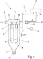
- a system 1 for cleaning exhaust gases comprises a filter container 2, on which an inlet 3 for a raw gas is provided, which flows into a filter chamber 4.
- a multiplicity of tubular or bag-shaped filter bodies 5 are provided in the filter chamber 4 and are positioned in the filter container 2 in a hanging or horizontally lying manner.
- the raw gas flows through the filter body 5 and thereby filters particles and other impurities.
- the cleaned raw gas can then leave the filter container 2 through an outlet 6.
- the filter body 5 preferably consist of a thin-walled, textile, air-permeable material.
- a plate 7 is provided in the filter chamber 4, on which a plurality of openings are formed, on each of which a tubular holder 8 is arranged.
- the holder 8 can be removably mounted on the plate 7 in a sealed manner, for example by means of clamping or snap-in connections.
- the tubular filter bodies 5 are held on the holder 8 at an upper end.
- a cleaning tube 9 is arranged above the filter body 5 and has openings or nozzles 10 which can introduce a pressure surge into the filter body 5 against the flow direction for cleaning the filter body 5.
- the cleaning pipe 9 is connected to a pressure vessel 13 which is fed with compressed air or another gas via a compressor 14.
- the cleaning pipe 9 is closed by a valve 20 that can be opened briefly, in particular a membrane valve or a plurality of valves connected in parallel.
- the valve 20 or a plurality of valves connected in parallel can be briefly opened, so that a pressure pulse is introduced into the filter body 5 through the cleaning tube 9.
- the number of valves 20 can be made dependent on the number of filter bodies 5 to be cleaned.
- the individual pressure pulses can be generated either by the same valves 20 or by different valves, which are then opened briefly with a time delay.
- a controller 15 which detects the pressure in the filter container 2 on both sides of the filter body 5 via lines 16 and 17 and also in the pressure container 13. Via the controller 15, a cleaning cycle for cleaning the filter body 5 can be controlled automatically.
- a cleaning cycle is represented by a pressure-time diagram.
- the at least one valve 20 or more valves connected in parallel can be opened so that the pressure in the cleaning tube 9 and the filter bodies 5 increases briefly.
- the opening time for the first pressure pulse can be, for example, between 40 ms and 150 ms.
- P 1 which can be, for example, between 1 bar and 4 bar.
- the opening time of at least one Valve 20 or more valves connected in parallel is the same, longer or shorter than in the first pressure pulse for the second pressure pulse, so that the maximum pressure P 2 is variable for the second pressure pulse.
- a third pressure pulse and possibly further pressure pulses are generated after a further waiting time.
- a lower pressure P 3 is generated in the third pressure pulse than in the second pressure pulse.
- the cleaning cycle shown consists of three pressure pulses, whereby of course two pressure pulses or more than three pressure pulses can also be generated.
- a lower pressure P 3 is generated in the third pressure pulse than in the second pressure pulse.
- the level of the pressure pulses can also be chosen to be the same size.
- the number of pressure pulses and optionally also their length and / or the height of the pressure pulses can be varied by detecting the pressure loss when flowing through the filter body 5 and other parameters.
Landscapes
- Chemical & Material Sciences (AREA)
- Chemical Kinetics & Catalysis (AREA)
- Filtering Of Dispersed Particles In Gases (AREA)
Applications Claiming Priority (1)
| Application Number | Priority Date | Filing Date | Title |
|---|---|---|---|
| DE102018121134.1A DE102018121134A1 (de) | 2018-08-29 | 2018-08-29 | Verfahren zum Reinigen von Filtern |
Publications (1)
| Publication Number | Publication Date |
|---|---|
| EP3616772A1 true EP3616772A1 (fr) | 2020-03-04 |
Family
ID=67777192
Family Applications (1)
| Application Number | Title | Priority Date | Filing Date |
|---|---|---|---|
| EP19194075.8A Withdrawn EP3616772A1 (fr) | 2018-08-29 | 2019-08-28 | Procédé de nettoyage de filtres |
Country Status (2)
| Country | Link |
|---|---|
| EP (1) | EP3616772A1 (fr) |
| DE (1) | DE102018121134A1 (fr) |
Citations (8)
| Publication number | Priority date | Publication date | Assignee | Title |
|---|---|---|---|---|
| DE2709204A1 (de) * | 1977-03-03 | 1978-09-07 | Hess Gerhard Ing Grad | Verfahren zum reinigen stroemender gase sowie vorrichtung dazu |
| DE2754757A1 (de) * | 1977-07-15 | 1979-01-25 | Buehler Ag Geb | Gegenspuelverfahren insbesondere fuer schlauchfilter zur staubluftreinigung und filter mit gegenspuelung |
| DE7511735U (de) * | 1974-05-02 | 1980-10-30 | Ab Svenska Flaektfabriken, Nacka (Schweden) | Vorrichtung zur reinigung von stofffiltern von schlauchtyp o.dgl. |
| US4235610A (en) * | 1978-05-22 | 1980-11-25 | York-Shipley, Inc. | Apparatus in the fabric filter control of air pollution |
| EP0043417A2 (fr) * | 1980-07-05 | 1982-01-13 | Degussa Aktiengesellschaft | Procédé pour la purification de tissus filtrants au moyen d'impulsion de gaz comprimé lors de séparation de particules solides à partir de gaz |
| AT400228B (de) * | 1994-02-15 | 1995-11-27 | Scheuch Alois Gmbh | Verfahren zur abreinigung der gewebefilterelemente in kammerfilter-anlagen |
| EP1997547A1 (fr) | 2007-06-01 | 2008-12-03 | Balcke-Dürr GmbH | Procédé destiné au rétrolavage de filtres |
| EP2602016A1 (fr) | 2011-12-05 | 2013-06-12 | Jochen Deichmann | Installation de nettoyage de filtres et procédé d'actionnement d'une installation de nettoyage de filtres |
-
2018
- 2018-08-29 DE DE102018121134.1A patent/DE102018121134A1/de active Pending
-
2019
- 2019-08-28 EP EP19194075.8A patent/EP3616772A1/fr not_active Withdrawn
Patent Citations (8)
| Publication number | Priority date | Publication date | Assignee | Title |
|---|---|---|---|---|
| DE7511735U (de) * | 1974-05-02 | 1980-10-30 | Ab Svenska Flaektfabriken, Nacka (Schweden) | Vorrichtung zur reinigung von stofffiltern von schlauchtyp o.dgl. |
| DE2709204A1 (de) * | 1977-03-03 | 1978-09-07 | Hess Gerhard Ing Grad | Verfahren zum reinigen stroemender gase sowie vorrichtung dazu |
| DE2754757A1 (de) * | 1977-07-15 | 1979-01-25 | Buehler Ag Geb | Gegenspuelverfahren insbesondere fuer schlauchfilter zur staubluftreinigung und filter mit gegenspuelung |
| US4235610A (en) * | 1978-05-22 | 1980-11-25 | York-Shipley, Inc. | Apparatus in the fabric filter control of air pollution |
| EP0043417A2 (fr) * | 1980-07-05 | 1982-01-13 | Degussa Aktiengesellschaft | Procédé pour la purification de tissus filtrants au moyen d'impulsion de gaz comprimé lors de séparation de particules solides à partir de gaz |
| AT400228B (de) * | 1994-02-15 | 1995-11-27 | Scheuch Alois Gmbh | Verfahren zur abreinigung der gewebefilterelemente in kammerfilter-anlagen |
| EP1997547A1 (fr) | 2007-06-01 | 2008-12-03 | Balcke-Dürr GmbH | Procédé destiné au rétrolavage de filtres |
| EP2602016A1 (fr) | 2011-12-05 | 2013-06-12 | Jochen Deichmann | Installation de nettoyage de filtres et procédé d'actionnement d'une installation de nettoyage de filtres |
Also Published As
| Publication number | Publication date |
|---|---|
| DE102018121134A1 (de) | 2020-03-05 |
Similar Documents
| Publication | Publication Date | Title |
|---|---|---|
| AT410403B (de) | Verfahren und vorrichtung zur abreinigung von filtern für staubbelastete abgase | |
| EP1997547B1 (fr) | Procédé destiné au rétrolavage de filtres | |
| EP3212306B1 (fr) | Procédé de nettoyage et dispositif de commande | |
| EP4065252B1 (fr) | Procédé de nettoyage intermittent d'un filtre et dispositif de filtration pour un dispositif d'impression de métal | |
| EP3226996B1 (fr) | Dispositif de filtration, système hydraulique et procédé de lavage à contre-courant | |
| DE102014006473A1 (de) | Filtervorrichtung sowie Verfahren zur Reinigung wenigstens eines Filterelementes, insbesondere unter Verwendung einer solchen Filtervorrichtung | |
| DE102011056062A1 (de) | Anlage zum Reinigen von Filtern und Verfahren zum Betreiben einer Anlage zum Reinigen von Filtern | |
| DE3428428C2 (fr) | ||
| DE102014219569B4 (de) | Wasserfiltereinrichtung mit rückspülbarem Wasserfilter mit Fließgeschwindigkeitsreduktion und Verfahren zum Rückspülen eines Wasserfilters | |
| DE2065715A1 (de) | Vorrichtung zum entfernen fester rueckstaende und zum reinigen schlauch- oder beutelfoermiger filter | |
| EP3616772A1 (fr) | Procédé de nettoyage de filtres | |
| DE1214200B (de) | Rueckspuelbare Filtrieranlage | |
| DE102005033314B4 (de) | Verfahren und Filteranlage zum Filtern von Rohwasser | |
| EP2656897B1 (fr) | Procédé et dispositif de filtration de particules à partir de gaz | |
| WO2008089833A1 (fr) | Installation de filtration | |
| DE1436267A1 (de) | Rueckspuelfilter | |
| DE102006001034A1 (de) | Verfahren und Filteranlage zum Filtern von Rohwasser | |
| WO2003099419A1 (fr) | Dispositif de nettoyage pour des elements de filtre tubulaires | |
| DE9000579U1 (de) | Filtrationsapparat zur Heißgasreinigung mittels Spaltkerzenfilter | |
| DE3918267A1 (de) | Druckfilter | |
| DE1811039A1 (de) | Verfahren und Vorrichtung zum Abscheiden teilchenfoermiger Stoffe aus einem gasfoermigen Traegermedium | |
| DE4330644C1 (de) | Filternder Abscheider | |
| DE202006000174U1 (de) | Filteranlage zum Filtern von Rohwasser | |
| WO1999055442A1 (fr) | Injecteur a fente annulaire | |
| EP1105202A2 (fr) | Injecteur a fente annulaire |
Legal Events
| Date | Code | Title | Description |
|---|---|---|---|
| PUAI | Public reference made under article 153(3) epc to a published international application that has entered the european phase |
Free format text: ORIGINAL CODE: 0009012 |
|
| AK | Designated contracting states |
Kind code of ref document: A1 Designated state(s): AL AT BE BG CH CY CZ DE DK EE ES FI FR GB GR HR HU IE IS IT LI LT LU LV MC MK MT NL NO PL PT RO RS SE SI SK SM TR |
|
| AX | Request for extension of the european patent |
Extension state: BA ME |
|
| STAA | Information on the status of an ep patent application or granted ep patent |
Free format text: STATUS: THE APPLICATION IS DEEMED TO BE WITHDRAWN |
|
| 18D | Application deemed to be withdrawn |
Effective date: 20200905 |