EP3616858A2 - Procédé et dispositif de documentation d'un état d'un robot autonome - Google Patents
Procédé et dispositif de documentation d'un état d'un robot autonome Download PDFInfo
- Publication number
- EP3616858A2 EP3616858A2 EP19188788.4A EP19188788A EP3616858A2 EP 3616858 A2 EP3616858 A2 EP 3616858A2 EP 19188788 A EP19188788 A EP 19188788A EP 3616858 A2 EP3616858 A2 EP 3616858A2
- Authority
- EP
- European Patent Office
- Prior art keywords
- autonomous robot
- signal
- environment
- robot
- status
- Prior art date
- Legal status (The legal status is an assumption and is not a legal conclusion. Google has not performed a legal analysis and makes no representation as to the accuracy of the status listed.)
- Withdrawn
Links
Images


Classifications
-
- B—PERFORMING OPERATIONS; TRANSPORTING
- B25—HAND TOOLS; PORTABLE POWER-DRIVEN TOOLS; MANIPULATORS
- B25J—MANIPULATORS; CHAMBERS PROVIDED WITH MANIPULATION DEVICES
- B25J9/00—Program-controlled manipulators
- B25J9/16—Program controls
- B25J9/1674—Program controls characterised by safety, monitoring, diagnostic
-
- B—PERFORMING OPERATIONS; TRANSPORTING
- B25—HAND TOOLS; PORTABLE POWER-DRIVEN TOOLS; MANIPULATORS
- B25J—MANIPULATORS; CHAMBERS PROVIDED WITH MANIPULATION DEVICES
- B25J11/00—Manipulators not otherwise provided for
-
- G—PHYSICS
- G05—CONTROLLING; REGULATING
- G05B—CONTROL OR REGULATING SYSTEMS IN GENERAL; FUNCTIONAL ELEMENTS OF SUCH SYSTEMS; MONITORING OR TESTING ARRANGEMENTS FOR SUCH SYSTEMS OR ELEMENTS
- G05B2219/00—Program-control systems
- G05B2219/30—Nc systems
- G05B2219/40—Robotics, robotics mapping to robotics vision
- G05B2219/40201—Detect contact, collision with human
-
- G—PHYSICS
- G05—CONTROLLING; REGULATING
- G05B—CONTROL OR REGULATING SYSTEMS IN GENERAL; FUNCTIONAL ELEMENTS OF SUCH SYSTEMS; MONITORING OR TESTING ARRANGEMENTS FOR SUCH SYSTEMS OR ELEMENTS
- G05B2219/00—Program-control systems
- G05B2219/30—Nc systems
- G05B2219/40—Robotics, robotics mapping to robotics vision
- G05B2219/40202—Human robot coexistence
-
- G—PHYSICS
- G05—CONTROLLING; REGULATING
- G05B—CONTROL OR REGULATING SYSTEMS IN GENERAL; FUNCTIONAL ELEMENTS OF SUCH SYSTEMS; MONITORING OR TESTING ARRANGEMENTS FOR SUCH SYSTEMS OR ELEMENTS
- G05B2219/00—Program-control systems
- G05B2219/30—Nc systems
- G05B2219/45—Nc applications
- G05B2219/45084—Service robot
Definitions
- the approach presented here relates to a method and a device for documenting a status of an autonomous robot in accordance with the main claims.
- the EP2631730B1 discloses a cleaning robot that has a sensor arrangement that has at least one camera unit. Images of a room ceiling can be taken using the camera unit.
- An autonomous robot can, for example, be a service robot that is designed to be able to provide services for people.
- An autonomous robot can in particular be a cleaning robot, for example for mowing the lawn, vacuuming, wiping the floor and / or windows.
- a service robot can also be understood to mean a monitoring robot for monitoring a public area, such as, for example, an airport or a train station.
- the autonomous robot can, for example, also be capable of real-time environmental monitoring in three-dimensional space and detect manipulating and / or vandalizing people in a dynamic environment.
- a status can be understood to mean, for example, a physical state of an autonomous robot.
- the state of the autonomous robot at a certain point in time can include all of the information that is required to fully describe the current properties of the autonomous robot.
- the physical state of the autonomous robot can, in particular, define all the observable properties of the autonomous robot and can unequivocally determine a physical state of the autonomous robot by means of a comparison with a predefined reference value or threshold value.
- An optical sensor can be sensors which detect objects, people and / or infrastructure features by means of light, within a certain spectrum and can thus trigger control, switching and regulating functions.
- an optical sensor can be a camera unit that is arranged, for example, on an autonomous robot and is also designed to continuously provide image information or images of an environment of the autonomous robot and the objects, people and / or infrastructure features located there capture and map.
- the optical sensor can be, for example, a mono or a stereo camera or a 3D camera that can record images in the visible and / or infrared range.
- a predefined reference value can be understood to mean a known, correct, non-optical measurement and / or threshold value for a physical state of an autonomous robot, wherein the reference value can be used or recorded, for example, during a measurement system analysis for comparison purposes.
- the reference value can also be preprogrammed in the autonomous robot, for example.
- An image signal can be an electrical signal from an optical sensor that represents, for example, an image of an environment of an autonomous robot.
- a central facility can be, for example, a technical, military or public facility where information from outside and inside is brought together and evaluated.
- a central facility can in particular be a processing unit, such as a control center and / or a fleet management system.
- a physical parameter can also be read in as a further environment signal in the reading step, the changed status of the autonomous robot being recognized in the step of recognizing by comparing the physical parameter with the predefined reference value.
- the at least one environment signal can be read in by an optical sensor of the autonomous robot in the reading step, the optical sensor being designed as a mono camera unit, a stereo camera unit and / or a 3D camera unit.
- the optical sensor being designed as a mono camera unit, a stereo camera unit and / or a 3D camera unit.
- a photographic apparatus such as a mono camera unit, a stereo camera unit and / or a 3D camera unit, static or moving images on a photographic film or electronically on a magnetic video tape or digital storage medium can be recorded and / or transmitted via an interface.
- the at least one environment signal and / or the further environment signal can be read in with a time stamp in the step of reading in, the time stamp also being output in the step of outputting.
- the time stamp can represent, for example, a point in time of an input, change and / or storage of the at least one environmental signal and / or the further environmental signal.
- step of recognizing when a recognized changed status of the autonomous robot is detected, face recognition can be carried out in order to recognize a person, with information about the recognized person being output in the step of issuing.
- face recognition can be carried out in order to recognize a person, with information about the recognized person being output in the step of issuing.
- Such an embodiment of the approach presented here offers the advantage that specific person characteristics of the recognized person can be extracted from the collected image data. A specific person can be clearly identified on the basis of these specific personal characteristics. In this way, an image of the manipulating and / or vandalizing person can be drawn from an image of the surroundings of the autonomous robot.
- the step of outputting information can be suppressed if the recognized person is recognized as authorized to perform actions on the autonomous robot.
- a pre-stored biometric factor can be used for the authentication of a person.
- a warning signal can also be output in the step of outputting when a recognized changed status of the autonomous robot.
- Such an embodiment of the approach presented here offers the advantage that an optical and / or acoustic warning or information about a fault state of the autonomous robot and / or manipulation and / or vandalism on the autonomous robot and / or in an environment of the autonomous robot can be transmitted to the central device quickly, easily and effectively and / or can be output directly to an environment of the autonomous robot. This can increase security in a public space in which the autonomous robot is located and / or provides a service, for example.
- a plurality of robot-external monitoring sensors in particular surveillance cameras, can be removed from the autonomous robot in the detection step on the basis of a detected changed status of the autonomous robot Robots and / or the central device are activated to read in a plurality of further environment signals.
- monitoring sensors can be used to observe public areas.
- a conspicuous object located in the surveillance area for example a person, is recorded by the surveillance camera.
- the image sequences and / or video sequences recorded by the surveillance cameras can be forwarded to a central unit, for example a surveillance center, and can be evaluated there by surveillance personnel and / or automatically.
- a sustainable improvement of the security situation in an environment of the autonomous robot can be achieved by means of a preventive and repressive effect of the image and / or video surveillance.
- the environment signals of the autonomous robot acquired in the step of reading in and / or the plurality of environment signals from the external monitoring sensors can be stored on a robot-internal storage unit, the environment signals generated for the signal being sent to an in the step of outputting central facility are issued.
- a robot-internal storage unit Such an embodiment of the approach presented here has the advantage that any manipulation processes that occur on the autonomous robot and / or special events in an environment of the autonomous robot are documented and sent to an authorized person and / or a central facility, for example a control center and / or a Fleet management system to be passed on. In this way, the current error status of the autonomous robot can be better assessed and consequently corrected quickly and efficiently.
- the approach presented here also creates a device for documenting a status of an autonomous robot, which is designed to carry out, control or implement the steps of a variant of a method presented here in corresponding devices.
- This embodiment variant of the invention in the form of a device can also be used to quickly and efficiently achieve the object on which the invention is based.
- the device can be designed to read input signals and to determine and provide output signals using the input signals.
- An input signal can represent, for example, a sensor signal that can be read in via an input interface of the device.
- An output signal can represent a control signal or a data signal that can be provided at an output interface of the device.
- the device can be designed to determine the output signals using a processing rule implemented in hardware or software.
- the device can be a logic circuit, an integrated one Include circuit or a software module and, for example, be implemented as a discrete component or be comprised by a discrete component.
- An autonomous robot for performing a service, in particular a cleaning service, and a device for documenting a status of an autonomous robot are presented.
- the device can be operated in a cloud platform.
- the cloud platform can be used to network the autonomous robot and the device for outputting the signal.
- processing data in an external computing unit means less computing power in the autonomous robot itself and the associated lower energy consumption or the possibility of using resources for other functions.
- the external computing unit has a larger available computing power than a robot-internal computer.
- the device and / or the method described here can correspondingly be used in connection with a commercial or professional autonomous robot, for example a surveillance robot for public areas and / or an autonomous robot for the medical field.
- a computer program product or computer program with program code which can be stored on a machine-readable carrier or storage medium such as a semiconductor memory, a hard disk memory or an optical memory, is also advantageous. If the program product or program is executed on a computer or a device, the program product or program can be used to carry out, implement and / or control the steps of the method according to one of the embodiments described above.
- Figure 1 shows a schematic representation of a manipulation situation 100 for using a method for documenting a status of an autonomous robot 102 according to an exemplary embodiment.
- the illustration shows the autonomous robot 102, with an unauthorized person 104 trying to manipulate the autonomous robot 102.
- the autonomous robot 102 has at least one optical sensor 106 or a plurality of optical sensors, for example stereo cameras, mono cameras and / or 3D cameras, for navigation.
- image recordings of an environment 108 of the autonomous robot 102 can also be taken using the optical sensor 106.
- Autonomous robots 102 often come into contact with a wide variety of groups of people, particularly in public areas. Here, there may be a risk that manipulation of the autonomous robot 102, theft of a transport item of the autonomous robot 102, hindrance of a function execution of the autonomous robot 102 and / or vandalism on the autonomous robot 102 by an unauthorized person 104 and / or an unauthorized group of people is made.
- manipulation situations 100 and / or special events can occur which should be monitored and documented by the autonomous robot 102, such as, for example, actuating an emergency switch of the autonomous robot 102, forcing transport containers of the autonomous robot 102 to open, shaking, lifting or even knocking over the autonomous robot 102, blocking the autonomous robot 102 so that it finds no way out, triggering a fire alarm of the autonomous robot 102 and / or triggering a fire alarm in an environment 108 of the autonomous robot 102, that Closing a door, in particular a fire protection door, an internal fault condition of the autonomous robot 102, such as, for example, an overcurrent of the wheel gear units and / or the triggering of a fall sensor of the autonomous robot 102 due to a detected fall edge.
- an emergency switch of the autonomous robot 102 forcing transport containers of the autonomous robot 102 to open, shaking, lifting or even knocking over the autonomous robot 102, blocking the autonomous robot 102 so that it finds no way out, triggering a fire alarm of the autonomous robot 102 and / or triggering
- All of these manipulation processes 100 and / or special events are to be documented and passed on to an authorized person and / or a central facility, for example a control center and / or a fleet management system. In this way, the current error status of the autonomous robot 102 can be better assessed and consequently eliminated quickly and efficiently.
- an actual recording of sensor data such as image data and / or physical status data of the autonomous robot 102, on an internal robot Storage unit and / or temporarily stored on an external computing unit, for example a cloud platform.
- photos should be taken of the optical sensor 106 of the autonomous robot 102 and / or at least one surveillance sensor, for example a surveillance camera in the vicinity 108 of the autonomous robot 102, so that in the event of theft and / or manipulation 100 of the autonomous robot 102 and / or in an environment 108 of the autonomous robot 102, the manipulating person 104 can be recognized.
- a surveillance sensor for example a surveillance camera in the vicinity 108 of the autonomous robot 102
- an image and / or a plurality of images are recorded by means of the optical sensor 106 and these are collected and stored as a status message or passed on to a processing point.
- the recorded images and the physical state data of the autonomous robot 102 are provided with a time stamp and stored in order to be able to make an even more detailed statement about the state of the autonomous robot 102 and / or the environment 108 of the autonomous robot 102.
- Figure 2 shows a block diagram of a device 200 for documenting a status of an autonomous robot 102 according to an embodiment.
- the device 200 is arranged, for example, on the autonomous robot 102, in particular a service robot for cleaning tasks. Additionally or alternatively, the device 200 can also be arranged on an external computing unit, for example a cloud platform.
- the autonomous robot 102 has at least one optical sensor 106, the optical sensor 106 being, for example, a mono camera unit, a stereo camera unit and / or a 3D camera unit for optically and sensorily detecting an environment 108 of the autonomous robot 102 .
- the device 200 has a reading unit 205, a recognition unit 210 and an output unit 215.
- the reading unit 205 is designed, for example, to read in at least one environment signal 220 from the optical sensor 106.
- the at least one environment signal 220 represents the environment 108 of the autonomous robot 102.
- the reading unit 205 is, for example, further configured to read a physical parameter 225 of the autonomous robot 102 as a further environment signal 225.
- the read-in unit 205 is designed to take the physical parameter 225 from an emergency stop switch 230 of the autonomous robot 102 and / or a sensor 235 of the autonomous robot 102 for detecting an external force effect on the autonomous robot 102 and / or an internal error sensor 240 des autonomous robot 102 and / or a crash sensor 245 of the autonomous robot 102.
- the read-in unit 205 is designed to have the at least one environment signal 220 and / or the further environment signal 225 Read in the time stamp, the time stamp representing a point in time of an input, change and / or storage of the at least one environment signal 220 and / or the further environment signal 225.
- the autonomous robot 102 can have a robot-internal storage unit 250, the robot-internal storage unit 250 being designed to temporarily store the at least one environment signal 220 and / or the further environment signal 225.
- the recognition unit 210 is designed to recognize a changed status of the autonomous robot 102 when the at least one environment signal 220 and / or the further environment signal 225 is related to a predefined reference value.
- the recognition unit 210 is further configured to compare the at least one optical environment signal 220 and / or the physical parameter 225 with the predefined reference value.
- the recognition unit 210 is designed to carry out face recognition when the changed status of the autonomous robot 102 is recognized. For this purpose, a machine learning method and / or a neural network for localizing a face in an image recorded by the optical sensor 106 and the assignment of the face to a specific person can be preprogrammed on the recognition unit 210.
- the algorithms behind this are trained with the help of large data sets, i.e. a large number of images.
- the machine learning process uses, for example, a multi-layer neural network that adjusts its parameters in the training phase until a person's face can be reliably recognized and saved as authorized.
- the recognition unit 210 can be designed to activate a plurality of external monitoring sensors, for example at least one surveillance camera 255, which is arranged in the environment 108 of the autonomous robot 102, using an activation signal 260 on the basis of a recognized changed status of the autonomous robot 102, so that the surveillance camera 255 reads in a plurality of environment signals.
- This plurality of environment signals can also optionally be temporarily stored on the robot-internal storage unit 250 of the autonomous robot 102.
- the output unit 215 is designed to output an image signal 270 to the central device using a status signal 265 provided by the recognition unit 210, which represents a recognized changed status of the autonomous robot 102, in order to output the changed status of the autonomous robot Robot 102 report.
- the image signal 270 can represent an electrical signal of the optical sensor 106, which for example represents an image of the environment 108 of the autonomous robot 102.
- the output unit 215 is further configured to output a warning signal 275 when the changed status of the autonomous robot 102 is detected.
- the warning signal 275 can be output, for example, to the central device and / or optically and / or acoustically to the direct environment 108 of the autonomous robot 102.
- the output unit 215 is finally designed to output information about a recognized person who is in the environment 108 of the autonomous robot 102 and possibly to be responsible for the changed status of the autonomous robot 102 in the form of an information signal 280 to the central device.
- output of the information signal 280 to the central device is suppressed when the recognized person is recognized by the recognition unit 210 as authorized, wherein a recognized face of the person can be used as a biometric factor for the authentication.
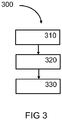
- Figure 3 shows a flowchart of an embodiment of a method 300 for documenting a status of an autonomous robot according to an embodiment.
- the method 300 can, for example, use the method based on Figure 1 described device for documenting a status of an autonomous robot.
- the method 300 initially has a step 310 in which at least one environment signal, which represents an environment of the autonomous robot, is read in by an optical sensor.
- the method 300 subsequently has a step 320, in which a changed status of the autonomous robot is recognized when the at least one environment signal is related to a predefined reference value.
- the method 300 has a step 330 in which an image signal is output to a central device in order to report the changed status of the autonomous robot.
Landscapes
- Engineering & Computer Science (AREA)
- Robotics (AREA)
- Mechanical Engineering (AREA)
- Manipulator (AREA)
Applications Claiming Priority (1)
| Application Number | Priority Date | Filing Date | Title |
|---|---|---|---|
| DE102018121110.4A DE102018121110A1 (de) | 2018-08-29 | 2018-08-29 | Verfahren und Vorrichtung zur Dokumentation eines Status eines autonomen Roboters |
Publications (2)
| Publication Number | Publication Date |
|---|---|
| EP3616858A2 true EP3616858A2 (fr) | 2020-03-04 |
| EP3616858A3 EP3616858A3 (fr) | 2020-03-25 |
Family
ID=67514306
Family Applications (1)
| Application Number | Title | Priority Date | Filing Date |
|---|---|---|---|
| EP19188788.4A Withdrawn EP3616858A3 (fr) | 2018-08-29 | 2019-07-29 | Procédé et dispositif de documentation d'un état d'un robot autonome |
Country Status (2)
| Country | Link |
|---|---|
| EP (1) | EP3616858A3 (fr) |
| DE (1) | DE102018121110A1 (fr) |
Cited By (1)
| Publication number | Priority date | Publication date | Assignee | Title |
|---|---|---|---|---|
| CN114666476A (zh) * | 2022-03-15 | 2022-06-24 | 北京云迹科技股份有限公司 | 机器人智能录像方法、装置、设备及存储介质 |
Families Citing this family (1)
| Publication number | Priority date | Publication date | Assignee | Title |
|---|---|---|---|---|
| CN115761464B (zh) * | 2022-11-03 | 2023-09-19 | 中山大学 | 一种水下机器人作业环境与状态的评估方法 |
Citations (1)
| Publication number | Priority date | Publication date | Assignee | Title |
|---|---|---|---|---|
| EP2631730A1 (fr) | 2012-02-24 | 2013-08-28 | Samsung Electronics Co., Ltd | Capteur combiné et robot nettoyeur muni dudit capteur |
Family Cites Families (2)
| Publication number | Priority date | Publication date | Assignee | Title |
|---|---|---|---|---|
| US20130117867A1 (en) * | 2011-11-06 | 2013-05-09 | Hei Tao Fung | Theft Prevention for Networked Robot |
| JP6562736B2 (ja) * | 2015-06-29 | 2019-08-21 | シャープ株式会社 | 自律走行装置 |
-
2018
- 2018-08-29 DE DE102018121110.4A patent/DE102018121110A1/de not_active Withdrawn
-
2019
- 2019-07-29 EP EP19188788.4A patent/EP3616858A3/fr not_active Withdrawn
Patent Citations (1)
| Publication number | Priority date | Publication date | Assignee | Title |
|---|---|---|---|---|
| EP2631730A1 (fr) | 2012-02-24 | 2013-08-28 | Samsung Electronics Co., Ltd | Capteur combiné et robot nettoyeur muni dudit capteur |
Cited By (2)
| Publication number | Priority date | Publication date | Assignee | Title |
|---|---|---|---|---|
| CN114666476A (zh) * | 2022-03-15 | 2022-06-24 | 北京云迹科技股份有限公司 | 机器人智能录像方法、装置、设备及存储介质 |
| CN114666476B (zh) * | 2022-03-15 | 2024-04-16 | 北京云迹科技股份有限公司 | 机器人智能录像方法、装置、设备及存储介质 |
Also Published As
| Publication number | Publication date |
|---|---|
| EP3616858A3 (fr) | 2020-03-25 |
| DE102018121110A1 (de) | 2020-03-05 |
Similar Documents
| Publication | Publication Date | Title |
|---|---|---|
| CN112042184B (zh) | 影像处理装置、影像处理系统以及影像处理方法 | |
| EP4105101A1 (fr) | Système de surveillance, procédé de surveillance et dispositif de surveillance pour train ferroviaire | |
| DE60005380T2 (de) | Überwachungssystem | |
| US8107680B2 (en) | Monitoring an environment | |
| US7428314B2 (en) | Monitoring an environment | |
| EP3401844A1 (fr) | Moteur d'inférence pour la détection d'événement et la recherche légiste sur la base de métadonnées d'analyse vidéo | |
| EP2220627B1 (fr) | Système de surveillance avec module de détection d'état, procédé d'autosurveillance d'un observateur, et programme informatique | |
| EP3701340A1 (fr) | Dispositif de surveillance, équipement industriel, procédé de surveillance et programme informatique | |
| DE112017000231T5 (de) | Detektion der Lebendigkeit für die Gesichtserkennung mit Täuschungsverhinderung | |
| KR101036947B1 (ko) | 컴퓨터 영상 분석기술을 이용한 범죄 및 사고예방 자동경비 시스템 | |
| DE102014105351A1 (de) | Detektion von menschen aus mehreren ansichten unter verwendung einer teilumfassenden suche | |
| DE112016006300T5 (de) | Vorrichtung zur Überwachung unbeaufsichtigter Objekte, mit derselben ausgestattetes System zur Überwachung unbeaufsichtigter Objekte und Verfahren zur Überwachung unbeaufsichtigter Objekte | |
| CN112329691A (zh) | 一种监控视频的分析方法及装置、电子设备、存储介质 | |
| EP3808616B1 (fr) | Protection par caméra pour installations de traitement des véhicules | |
| DE102018121110A1 (de) | Verfahren und Vorrichtung zur Dokumentation eines Status eines autonomen Roboters | |
| AT510352A1 (de) | Kamera für die unkenntlichmachung personenbezogener daten | |
| DE102017222898A1 (de) | Automatisiertes Detektieren von Gefahrensituationen | |
| DE102014200567A1 (de) | Verfahren zur automatischen Übertragung von Bild- und/oder Audiodaten im Zusammenhang mit einem Unfall eines Fahrzeugs | |
| EP2603905B1 (fr) | Procédé et dispositif de détection et de vérification de tentatives de manipulation sur un terminal de distribution automatique | |
| KR20230043262A (ko) | 입체 영상관제 기반의 공사현장 안전관리 시스템 | |
| DE102018222683A1 (de) | Verfahren zum Erstellen einer Umgebungsrepräsentationskarte zur Überwachung eines Fahrzeugs und/oder eines Fahrzeuganhängers unter Verwendung eines Kamerasystems | |
| CN106127903A (zh) | 电子设备探测门禁管控装置及其方法 | |
| DE102017219292A1 (de) | Verfahren und vorrichtung zum erfassen von ereignisbezogenen daten bezüglich eines fahrzeugs | |
| DE102017109370A1 (de) | Verfahren zur Überwachung mittels eines fernsteuerbaren Fahrzeugs, insbesondere einer Drohne | |
| KR20150031059A (ko) | 패턴 인식 기술에 의한 범죄 예방 폐쇄 회로 티비 장치 개선 |
Legal Events
| Date | Code | Title | Description |
|---|---|---|---|
| PUAI | Public reference made under article 153(3) epc to a published international application that has entered the european phase |
Free format text: ORIGINAL CODE: 0009012 |
|
| STAA | Information on the status of an ep patent application or granted ep patent |
Free format text: STATUS: THE APPLICATION HAS BEEN PUBLISHED |
|
| PUAL | Search report despatched |
Free format text: ORIGINAL CODE: 0009013 |
|
| AK | Designated contracting states |
Kind code of ref document: A2 Designated state(s): AL AT BE BG CH CY CZ DE DK EE ES FI FR GB GR HR HU IE IS IT LI LT LU LV MC MK MT NL NO PL PT RO RS SE SI SK SM TR |
|
| AX | Request for extension of the european patent |
Extension state: BA ME |
|
| AK | Designated contracting states |
Kind code of ref document: A3 Designated state(s): AL AT BE BG CH CY CZ DE DK EE ES FI FR GB GR HR HU IE IS IT LI LT LU LV MC MK MT NL NO PL PT RO RS SE SI SK SM TR |
|
| AX | Request for extension of the european patent |
Extension state: BA ME |
|
| RIC1 | Information provided on ipc code assigned before grant |
Ipc: B25J 9/00 20060101ALI20200215BHEP Ipc: B25J 9/16 20060101AFI20200215BHEP |
|
| 18D | Application deemed to be withdrawn |
Effective date: 20200926 |