EP3616877B1 - Ventil - Google Patents
Ventil Download PDFInfo
- Publication number
- EP3616877B1 EP3616877B1 EP19187665.5A EP19187665A EP3616877B1 EP 3616877 B1 EP3616877 B1 EP 3616877B1 EP 19187665 A EP19187665 A EP 19187665A EP 3616877 B1 EP3616877 B1 EP 3616877B1
- Authority
- EP
- European Patent Office
- Prior art keywords
- channel
- segment
- valve
- communication
- tapered
- Prior art date
- Legal status (The legal status is an assumption and is not a legal conclusion. Google has not performed a legal analysis and makes no representation as to the accuracy of the status listed.)
- Active
Links
Images


Classifications
-
- B—PERFORMING OPERATIONS; TRANSPORTING
- B29—WORKING OF PLASTICS; WORKING OF SUBSTANCES IN A PLASTIC STATE IN GENERAL
- B29C—SHAPING OR JOINING OF PLASTICS; SHAPING OF MATERIAL IN A PLASTIC STATE, NOT OTHERWISE PROVIDED FOR; AFTER-TREATMENT OF THE SHAPED PRODUCTS, e.g. REPAIRING
- B29C45/00—Injection moulding, i.e. forcing the required volume of moulding material through a nozzle into a closed mould; Apparatus therefor
- B29C45/17—Component parts, details or accessories; Auxiliary operations
- B29C45/18—Feeding the material into the injection moulding apparatus, i.e. feeding the non-plastified material into the injection unit
- B29C45/1816—Feeding auxiliary material, e.g. colouring material
- B29C2045/185—Feeding auxiliary material, e.g. colouring material controlling the amount of auxiliary material
-
- B—PERFORMING OPERATIONS; TRANSPORTING
- B29—WORKING OF PLASTICS; WORKING OF SUBSTANCES IN A PLASTIC STATE IN GENERAL
- B29C—SHAPING OR JOINING OF PLASTICS; SHAPING OF MATERIAL IN A PLASTIC STATE, NOT OTHERWISE PROVIDED FOR; AFTER-TREATMENT OF THE SHAPED PRODUCTS, e.g. REPAIRING
- B29C45/00—Injection moulding, i.e. forcing the required volume of moulding material through a nozzle into a closed mould; Apparatus therefor
- B29C45/17—Component parts, details or accessories; Auxiliary operations
- B29C45/18—Feeding the material into the injection moulding apparatus, i.e. feeding the non-plastified material into the injection unit
- B29C45/1866—Feeding multiple materials
Definitions
- the invention relates to the technique of fluid supply, and more particularly to a valve applied in the technique of polymer molding and processing to provide control of opening and closing of a supply passageway for fluid such as supercritical fluid, color paste, or any other additive to flow therein.
- Patent application publication EP 0911137 A1 discloses a valve having the features of the preamble of claim 1. Further valve assemblies are known frompatent application publications US 2012/0276235 A1 , EP 1052078 A1 and US 2004/0161490 A1 .
- the invention provides a valve having the features of claim 1. Further embodiments are subject-matter of the dependent claims.
- the valve according to the invention is disposed in a fluid supply path to control opening or closing of the supply path, configured to comprise, as components of the supply path, an inflow channel, a second channel, a first channel, and an outflow channel that are in communication with each other in sequence, in such a manner that fluid from a supply source entering the inflow channel passes through the second channel and the first channel in sequence and then flows out through the outflow channel.
- the valve further comprises a first valve piece and a second valve piece disposed movably in the first channel and the second channel respectively.
- Blocking or unblocking of the communication between the first channel and the outflow channel is controlled by movement of the first valve piece in the first channel, while blocking or unblocking of the communication between the inflow channel and the first channel via the second channel is controlled by movement of the second valve in the second channel.
- the valve enables opening or closing of the supply path through dual control by the first valve piece and the second valve piece.
- the valve further comprises a seat in which the inflow channel, the first channel, the second channel, and the outflow channel are disposed, and the first valve piece and the second valve piece are disposed slidably.
- first valve piece further comprises a first valve stem that is disposed slidably in the first channel and can move axially back and forth along its stem axis between a first closed position and a first opened position.
- the second valve piece further comprises a second valve stem that is disposed slidably in the second channel and can move axially back and forth along its stem axis between a second closed position and a second opened position.
- the first valve stem is segmented in sequence along its stem axis into a main shaft segment positioned in the first channel, an extended segment extended and positioned in the outflow channel, and an annular tapered face between the main shaft segment and the extended segment.
- the outflow channel has a tapered-segment inner wall face opposite to that tapered face and of the same slope as it.
- the second channel has a main body segment through which the second valve stem passes and disposed slidably and which is in communication with the inflow channel, and a connection segment of an inner diameter smaller than that of the main body segment for connecting the main body segment to the first channel.
- the second valve stem has cone-ended segment in a tapered shape on its end, and the end of the cone-ended segment extends from the main body segment into the connection segment.
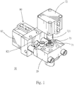
- a valve (10) according to a preferred embodiment of the invention comprises essentially a seat (20), a first channel (30), a second channel (40), an inflow channel (50), an outflow channel (60), a first valve piece (70), and a second valve piece (80).
- the seat (20) is a block having a shape and configuration that can be assembled and joined to other elements and a strength that can withstand the high pressure of the fluid.
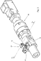
- the seat (20) is joined to an extrusion barrel or a mixing barrel of a polymer injection machine (90) shown in FIG. 3 and serves as part of a supply path for external fluid to be supplied into the extrusion barrel or the mixing barrel and mixed with the polymer material, and also as a base on which other constituent elements of the valve (10) are provided.
- the so-called external fluid is, for example, super-critical fluid, color Masterbatch, color paste, or any other additive in the state of fluid.
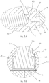
- the first channel (30) and the outflow channel (60) are straight holes passing through the seat (20) in coaxial communication with each other.
- the outflow channel (60) has an outflow segment (61) extending inwardly from the end face of an underside of the seat (20) to a suitable depth.
- a tapered segment (62) in the shape of a cone-shaped hole is positioned inside the seat (20) and connects the outflow segment (61) to the first channel (30).
- the inner diameter of the outflow segment (61) is larger than that of the first channel (30), so that the inner wall face (621) of the tapered segment (62) faces the outflow segment (61).
- the second channel (40) is a straight hole that extends inwardly from the left end face of the seat (20) and is in communication with and perpendicular to a middle portion of the first channel (30). Further, the second channel (40) is segmented in sequence along the hole axis into a main body segment (41) in communication with the outside on the left end face of the seat (20), a connection segment (42) of an inner diameter smaller than that of the main body segment (41) and connecting the main body segment (41) to the first channel (30), and a shoulder face (43) between the main body segment (41) and the connection segment (42).
- the inflow channel (50) extends from the top end of the seat (20) downwardly and obliquely to a location on the main body segment (41) close to the shoulder face (43) .
- the first valve piece (70) has a first valve stem (71) in the shape of a straight bar that passes coaxially through the first channel (30) and the outflow channel (60). Its top end extends above the seat (20) and its bottom end is positioned in the outflow channel (60).
- a first hydraulic cylinder (72) has an output shaft (721) pressed against the top end of the first valve stem (71).
- a compression spring (73) is sleeved over the portion of the first valve stem (71) that extends out of the seat (20), and provides an elastic force for the first valve stem (71) to move upwardly.
- first valve stem (71) is segmented along its stem axis into a main shaft segment (711) disposed slidably in the first channel (30), an extended segment (712) extending into the outflow channel (60), and an annular tapered face (713) between the main shaft segment (711) and the extended segment (712).
- the tapered face (713) is opposite to the inner wall face (621) of the tapered segment (62) and has the same tapering slope as it.
- the main shaft segment (711) has an outer diameter smaller than the inner diameter of the first channel (30), and the extended segment (712) has an outer diameter smaller than the inner diameter of the outflow segment (61) .
- the second valve piece (80) has a second valve stem (81) in the shape of a straight bar that passes slidably and coaxially through the main body segment (41) of the second channel (40) with its left end extending out of the left end face of the seat (20).
- a second hydraulic cylinder (82) has an output shaft (821) pressed against the left end of the second valve stem (81).
- the second valve stem (81) is segmented in sequence along its stem axis into a shaft body segment (811) disposed slidably in the second channel (40) and a cone-ended segment (812) is a tapered shape between the shaft body segment (811) and the connection segment (42) .
- first hydraulic cylinder (72) and the second hydraulic cylinder (82) are well known in the art. They are illustrated merely as the power source for actuation of the valve in the present embodiment. Therefore, although some parts are not fully depicted in the figures, they will not affect implementation of the invention by those of ordinary skills in the art.
- the first valve stem (71) can be moved back and forth axially in the first channel (30) and the outflow channel (60) along its stem axis between a first closed position and a first opened position.
- the second valve stem (81) can be moved back and forth axially in the second channel (40) along its stem axis between a second closed position and a second opened position.
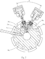
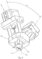
- the communication between the inflow channel (50) and the first channel (30) as well as the communication between the first channel (30) and the outflow segment (61) are blocked as shown in FIG. 4 .
- valve (10) can control flow of the fluid, so as to control the amount of fluid entering the extrusion barrel or the mixing barrel of the polymer injection machine (90) to be mixed with the polymer material.
- the elastic force of the compression spring (73) maintains the first valve stem (71) elastically in the first closed position.
- the tapered face (713) is in close contact with the inner wall face (621), thereby blocking the communication between the outflow segment (61) and the first channel (30).
- the first hydraulic cylinder (72) to push the first valve stem (71) downward via the output shaft (721) so as to cause the first valve stem (71) to move axially to the first opened position as shown in FIG.
- the tapered face (713) and the inner wall face (621) are separated from each other. Also, since the outer diameter of the main shaft segment (711) is smaller than that of the first channel (30) and the outer diameter of the extended segment (712) is smaller than that of the outflow segment (61), such a difference in size provides a gap therebetween for the fluid to flow therein.
- a space (s) between the circumferential side of the cone-ended segment (812) and the inner wall face of the main body segment (41) remains in communication with the inflow channel (50), thereby allowing the space (s) to be filled with the fluid that is still in communication with an external fluid supply via the inflow channel (50) .
- high pressure of the fluid acts continuously on the circumferential side face of the cone-ended segment (812). Therefore, once the external force applied by the second hydraulic cylinder (82) is released, the pressure of the fluid in the space (s) pushes the second valve stem (81) to the left till the second opened position as shown in FIG. 5 , thereby allowing the inflow channel (50) to be in communication indirectly with the first channel (30) via the second channel (40).
- valve (10a) according to the second preferred embodiment of the invention has the same essential technical characteristics as the one disclosed in the first preferred embodiment described above, but has better efficacy than the first preferred embodiment in maintaining the temperature of the fluid.
- the second channel (40a) and the first channel (30a) are in communication with each other with an acute included angle ( ⁇ ) therebetween, so that the connection segment (42a) is positioned closer to the center of the extrusion barrel or the mixing barrel of the polymer injection machine (90a).
- ⁇ acute included angle
- an approximately V-shaped connection is made between the second channel (40a) and the first channel (30a) to allow the portions of the channels connected to be positioned inside an insertion pillar (21a) protruding from the bottom end of the seat (20a) .
- the portions of the channels connected are covered by the extrusion barrel or mixing barrel of the polymer injection machine (90a), thereby avoiding temperature loss due to contact with the surroundings.
- the outflow segment (61a) of the outflow channel (60a) is further in communication with an undercut (22a) provided at the end of the insertion pillar (21a), so that the fluid flowing out via the outflow segment (61a) is dispersed via the undercut (22a) and then fed evenly into the extrusion barrel or mixing barrel of the polymer injection machine (90a) and mixed with the raw material.
Landscapes
- Engineering & Computer Science (AREA)
- Manufacturing & Machinery (AREA)
- Mechanical Engineering (AREA)
- Multiple-Way Valves (AREA)
Claims (12)
- Ventil (10), das in einer Fluid-Versorgungsleitung positioniert ist, um Öffnung und Schließung der Versorgungsleitung zu steuern, umfassend:einen Sitz (20),einen ersten Kanal (30), der in dem Sitz (20) angeordnet ist,einen zweiten Kanal (40), der in dem Sitz (20) angeordnet ist und mit dem ersten Kanal in Verbindung steht,einen Zuflusskanal (50), der in dem Sitz (20) angeordnet ist und mit dem zweiten Kanal (40) in Verbindung steht und über den zweiten Kanal (40) auch in indirekter Verbindung mit dem ersten Kanal (30) steht,einen Abflusskanal (60), der in dem Sitz (20) angeordnet ist und mit dem ersten Kanal (30) in Verbindung steht und auch über den ersten Kanal (30) und den zweiten Kanal (40) in indirekter Verbindung mit dem Zuflusskanal steht,ein erstes Ventilstück (70), das beweglich in dem ersten Kanal (30) angeordnet ist, wobei das erste Ventilstück (70) zwischen einer ersten Schließposition und einer ersten Öffnungsposition bewegt werden kann, wobei, wenn das erste Ventilstück (70) in der ersten Schließposition ist, die Verbindung zwischen dem ersten Kanal (30) und dem Abflusskanal (60) blockiert ist, wohingegen, wenn das erste Ventilstück (70) in der ersten Öffnungsposition ist, der erste Kanal (30) und der Abflusskanal (60) miteinander in Verbindung sind,ein zweites Ventilstück (80), das beweglich in dem zweiten Kanal (40) angeordnet ist, wobei das zweite Ventilstück (80) zwischen einer zweiten Schließposition und einer zweiten Öffnungposition bewegt werden kann, wobei, wenn sich das zweite Ventilstück (80) in der zweiten Schließposition befindet, die Verbindung zwischen dem Zuflusskanal (50) und dem ersten Kanal (30) blockiert ist, wohingegen, wenn sich das zweite Ventilstück (80) in der zweiten Öffnungsposition befindet, der erste Kanal (30) und der Zuflusskanal (50) in Verbindung miteinander sind,dadurch gekennzeichnet, dassder Sitz (20) so konfiguriert ist, dass er mit einem Extrusionszylinder oder einem Mischzylinder einer Polymerspritzmaschine (90) verbunden werden kann, um einen Teil eines Zuführungspfades für ein externes Fluid zu bilden, das in den Extrusionszylinder oder den Mischzylinder zugeführt werden soll.
- Ventil nach Anspruch 1, bei welchem das erste Ventilstück (70) einen in dem ersten Kanal (30) verschiebbar angeordneten ersten Ventilschaft (71) aufweist, der entlang seiner Schaftachse zwischen der ersten Schließposition und der ersten Öffnungsposition axial hin und her bewegbar ist.
- Ventil nach Anspruch 2, bei welchem der erste Ventilschaft (71) entlang seiner Schaftachse nacheinander segmentiert ist in ein Hauptschaftsegment (711), das in dem ersten Kanal (30) positioniert ist, ein in dem Abflusskanal (60) positioniertes erweitertes Segment (712) und eine ringförmige Konusfläche (713) zwischen dem Hauptschaftsegment (711) und dem erweiterten Segment (712).
- Ventil nach Anspruch 3, bei welchemder Abflusskanal (60) ein Abflusssegment (61) mit einem Innendurchmesser, der größer ist als der Innendurchmesser des ersten Kanals (30) und der Außendurchmesser des erweiterten Segments (712), und ein Konussegment (62) aufweist, das das Abflusssegment (61) mit dem ersten Kanal (30) verbindet, wobei die Innenwandfläche (621) des Konussegments (62) die gleiche Neigung aufweist wie die Konusfläche (713), und wobei,wenn der erste Ventilschaft (71) in der ersten Schließposition ist, die Konusfläche (713) dann in engem Kontakt mit der Innenwandfläche (621) des Konussegments (62) steht, um das Konussegment (62) zu blockieren, wohingegen, wenn der erste Ventilschaft (71) in der ersten Öffnungposition ist, die Konusfläche (713) von der Innenwandfläche (621) des Konussegments (62) getrennt ist.
- Ventil nach Anspruch 4, bei welchem der erste Kanal (30) und der Abflusskanal (60) in koaxialer Verbindung zueinander durch den Sitz verlaufen.
- Ventil nach Anspruch 1, bei welchem der zweite Kanal (40) ein Hauptkörpersegment (41) und ein Verbindungssegment (42) aufweist, welches das Hauptkörpersegment (41) mit dem ersten Kanal (30) verbindet, wobei das Verbindungssegment (42) einen Innendurchmesser aufweist, der kleiner ist als der Innendurchmesser des Hauptkörpersegments (41), um eine Öffnung zu bilden, die mit dem Hauptkörpersegment (41) in Verbindung steht.
- Ventil nach Anspruch 6, bei welchem der Zuflusskanal (50) mit dem Hauptkörpersegment (41) an einer Stelle verbunden ist, die an das Verbindungssegment (42) angrenzt.
- Ventil nach Anspruch 7, bei welchem das zweite Ventilstück (80) einen im Hauptkörpersegment (41) verschiebbar angeordneten zweiten Ventilschaft (81) aufweist, der entlang seiner Schaftachse zwischen der zweiten Schließposition und der zweiten Öffnungsposition axial hin- und herbewegt werden kann.
- Ventil nach Anspruch 8, bei welchemder zweite Ventilschaft (81) entlang seiner Schaftachse in ein im Hauptkörpersegment (41) positioniertes Schaftkörpersegment (811) und ein kegelförmiges Segment (812) unterteilt ist, wobei sich das Ende des kegelförmigen Segments (812) in das Verbindungselement (42) erstrecken kann, wobei,wenn der zweite Ventilschaft (81) in der zweiten Öffnungsposition ist, das Ende des kegelförmigen Segments (812) dann im Verbindungssegment (42) positioniert ist, während die konische Abschrägung an der Umfangsseite des kegelförmigen Segments (812) gegen die Öffnung im Verbindungselement gedrückt wird, um die Verbindung zwischen dem Verbindungselement (42) und dem Hauptkörpersegment (41) zu blockieren, und wobei,wenn der zweite Ventilschaft (81) in der zweiten Öffnungsposition ist, die konische Abschrägung an der Umfangsseite des kegelförmigen Segments (812) von der Öffnung in dem Verbindungssegment (42) getrennt ist, um das Hauptkörpersegment (41) und das Verbindungssegment miteinander in Verbindung zu bringen.
- Ventil nach Anspruch 9, bei welchem, wenn der zweite Ventilschaft (81) in der zweiten Schließposition ist, der Raum zwischen der inneren Seitenwandfläche (621) des Hauptkörpersegments (41) und der konischen Abschrägung an der Umfangsseite des kegelförmigen Segments (812) in Verbindung mit dem Zuflusskanal (50) steht.
- Ventil nach Anspruch 1, bei welchem der erste Kanal (30) und der zweite Kanal (40) in Verbindung mit und senkrecht zueinander stehen.
- Ventil nach Anspruch 1, bei welchem der erste Kanal (30) und der zweite Kanal (40) miteinander in Verbindung stehen und durch einen spitzen eingeschlossenen Winkel getrennt sind.
Applications Claiming Priority (2)
| Application Number | Priority Date | Filing Date | Title |
|---|---|---|---|
| TW107129970 | 2018-08-28 | ||
| TW107131644A TWI676754B (zh) | 2018-08-28 | 2018-09-08 | 閥 |
Publications (2)
| Publication Number | Publication Date |
|---|---|
| EP3616877A1 EP3616877A1 (de) | 2020-03-04 |
| EP3616877B1 true EP3616877B1 (de) | 2021-09-29 |
Family
ID=67438461
Family Applications (1)
| Application Number | Title | Priority Date | Filing Date |
|---|---|---|---|
| EP19187665.5A Active EP3616877B1 (de) | 2018-08-28 | 2019-07-22 | Ventil |
Country Status (1)
| Country | Link |
|---|---|
| EP (1) | EP3616877B1 (de) |
Family Cites Families (6)
| Publication number | Priority date | Publication date | Assignee | Title |
|---|---|---|---|---|
| US5972258A (en) * | 1997-10-20 | 1999-10-26 | Husky Injection Molding Systems Ltd. | Method of using a multiple gating nozzle |
| JP3285830B2 (ja) * | 1998-10-26 | 2002-05-27 | 積水化学工業株式会社 | 熱可塑性樹脂成形品の製造方法およびこの製造方法に用いる熱可塑性樹脂成形品の製造装置 |
| EP1052078A1 (de) * | 1999-05-08 | 2000-11-15 | HEKUMA Herbst Maschinenbau GmbH | Individuelle Prozessteuerung im Werkzeug |
| DE60133212T2 (de) | 2000-10-24 | 2009-03-19 | Trexel, Inc., Woburn | Ventil für das spritzgiessen |
| CN100411850C (zh) * | 2003-02-13 | 2008-08-20 | 标准模具有限公司 | 具有独立流量控制的阀浇口式注射成型系统 |
| EP2519393B1 (de) * | 2009-12-31 | 2015-04-08 | Husky Injection Molding Systems S.A. | Formkanalsystem mit unabhängig steuerbaren vorkammeranordnungen |
-
2019
- 2019-07-22 EP EP19187665.5A patent/EP3616877B1/de active Active
Also Published As
| Publication number | Publication date |
|---|---|
| EP3616877A1 (de) | 2020-03-04 |
Similar Documents
| Publication | Publication Date | Title |
|---|---|---|
| US2931385A (en) | Anti-scoring check valve | |
| JP7214883B2 (ja) | 電子膨張弁 | |
| JP5697072B2 (ja) | ボールバルブ | |
| US20030140974A1 (en) | Pilot control valve | |
| US20110297262A1 (en) | Hydraulic valve | |
| EP2947359B1 (de) | Absperrschieber | |
| EP3616877B1 (de) | Ventil | |
| US3614057A (en) | Flow control valve | |
| KR20070013239A (ko) | 스로틀 밸브가 부착된 유체압 실린더 장치 | |
| US11131391B2 (en) | Valve | |
| US5328148A (en) | Control device for hydraulic piston/cylinder unit | |
| US3990680A (en) | Valve construction and method of making the same | |
| CA2687054A1 (en) | Rotary valve assembly for an injection nozzle | |
| US6016838A (en) | Valve construction | |
| US4742850A (en) | Female coupling component forming part of a quick coupling | |
| TWI778012B (zh) | 用於容許特別是在高壓範圍內的介質通過之裝置的密封系統 | |
| US5172886A (en) | Fluid flow control valve assembly | |
| US2192835A (en) | Valve for controlling fluids | |
| CN220566584U (zh) | 控制阀 | |
| KR100522499B1 (ko) | 2포트 밸브 | |
| KR101205597B1 (ko) | 토치용 가스 조절 밸브 | |
| US10436330B2 (en) | Non-rising stem globe valve | |
| CN107956902B (zh) | 节流阀 | |
| CS228251B1 (en) | Fittings,particularly a valve with double control of a passage | |
| CN112539283B (zh) | 一种流量控制阀 |
Legal Events
| Date | Code | Title | Description |
|---|---|---|---|
| PUAI | Public reference made under article 153(3) epc to a published international application that has entered the european phase |
Free format text: ORIGINAL CODE: 0009012 |
|
| STAA | Information on the status of an ep patent application or granted ep patent |
Free format text: STATUS: THE APPLICATION HAS BEEN PUBLISHED |
|
| AK | Designated contracting states |
Kind code of ref document: A1 Designated state(s): AL AT BE BG CH CY CZ DE DK EE ES FI FR GB GR HR HU IE IS IT LI LT LU LV MC MK MT NL NO PL PT RO RS SE SI SK SM TR |
|
| AX | Request for extension of the european patent |
Extension state: BA ME |
|
| STAA | Information on the status of an ep patent application or granted ep patent |
Free format text: STATUS: REQUEST FOR EXAMINATION WAS MADE |
|
| 17P | Request for examination filed |
Effective date: 20200806 |
|
| RBV | Designated contracting states (corrected) |
Designated state(s): AL AT BE BG CH CY CZ DE DK EE ES FI FR GB GR HR HU IE IS IT LI LT LU LV MC MK MT NL NO PL PT RO RS SE SI SK SM TR |
|
| GRAP | Despatch of communication of intention to grant a patent |
Free format text: ORIGINAL CODE: EPIDOSNIGR1 |
|
| STAA | Information on the status of an ep patent application or granted ep patent |
Free format text: STATUS: GRANT OF PATENT IS INTENDED |
|
| INTG | Intention to grant announced |
Effective date: 20210408 |
|
| GRAS | Grant fee paid |
Free format text: ORIGINAL CODE: EPIDOSNIGR3 |
|
| GRAA | (expected) grant |
Free format text: ORIGINAL CODE: 0009210 |
|
| STAA | Information on the status of an ep patent application or granted ep patent |
Free format text: STATUS: THE PATENT HAS BEEN GRANTED |
|
| AK | Designated contracting states |
Kind code of ref document: B1 Designated state(s): AL AT BE BG CH CY CZ DE DK EE ES FI FR GB GR HR HU IE IS IT LI LT LU LV MC MK MT NL NO PL PT RO RS SE SI SK SM TR |
|
| REG | Reference to a national code |
Ref country code: GB Ref legal event code: FG4D |
|
| REG | Reference to a national code |
Ref country code: CH Ref legal event code: EP Ref country code: AT Ref legal event code: REF Ref document number: 1433823 Country of ref document: AT Kind code of ref document: T Effective date: 20211015 |
|
| REG | Reference to a national code |
Ref country code: DE Ref legal event code: R096 Ref document number: 602019007953 Country of ref document: DE |
|
| REG | Reference to a national code |
Ref country code: IE Ref legal event code: FG4D |
|
| REG | Reference to a national code |
Ref country code: LT Ref legal event code: MG9D |
|
| PG25 | Lapsed in a contracting state [announced via postgrant information from national office to epo] |
Ref country code: BG Free format text: LAPSE BECAUSE OF FAILURE TO SUBMIT A TRANSLATION OF THE DESCRIPTION OR TO PAY THE FEE WITHIN THE PRESCRIBED TIME-LIMIT Effective date: 20211229 Ref country code: LT Free format text: LAPSE BECAUSE OF FAILURE TO SUBMIT A TRANSLATION OF THE DESCRIPTION OR TO PAY THE FEE WITHIN THE PRESCRIBED TIME-LIMIT Effective date: 20210929 Ref country code: HR Free format text: LAPSE BECAUSE OF FAILURE TO SUBMIT A TRANSLATION OF THE DESCRIPTION OR TO PAY THE FEE WITHIN THE PRESCRIBED TIME-LIMIT Effective date: 20210929 Ref country code: NO Free format text: LAPSE BECAUSE OF FAILURE TO SUBMIT A TRANSLATION OF THE DESCRIPTION OR TO PAY THE FEE WITHIN THE PRESCRIBED TIME-LIMIT Effective date: 20211229 Ref country code: RS Free format text: LAPSE BECAUSE OF FAILURE TO SUBMIT A TRANSLATION OF THE DESCRIPTION OR TO PAY THE FEE WITHIN THE PRESCRIBED TIME-LIMIT Effective date: 20210929 Ref country code: SE Free format text: LAPSE BECAUSE OF FAILURE TO SUBMIT A TRANSLATION OF THE DESCRIPTION OR TO PAY THE FEE WITHIN THE PRESCRIBED TIME-LIMIT Effective date: 20210929 Ref country code: FI Free format text: LAPSE BECAUSE OF FAILURE TO SUBMIT A TRANSLATION OF THE DESCRIPTION OR TO PAY THE FEE WITHIN THE PRESCRIBED TIME-LIMIT Effective date: 20210929 |
|
| REG | Reference to a national code |
Ref country code: NL Ref legal event code: MP Effective date: 20210929 |
|
| REG | Reference to a national code |
Ref country code: AT Ref legal event code: MK05 Ref document number: 1433823 Country of ref document: AT Kind code of ref document: T Effective date: 20210929 |
|
| PG25 | Lapsed in a contracting state [announced via postgrant information from national office to epo] |
Ref country code: LV Free format text: LAPSE BECAUSE OF FAILURE TO SUBMIT A TRANSLATION OF THE DESCRIPTION OR TO PAY THE FEE WITHIN THE PRESCRIBED TIME-LIMIT Effective date: 20210929 Ref country code: GR Free format text: LAPSE BECAUSE OF FAILURE TO SUBMIT A TRANSLATION OF THE DESCRIPTION OR TO PAY THE FEE WITHIN THE PRESCRIBED TIME-LIMIT Effective date: 20211230 |
|
| PG25 | Lapsed in a contracting state [announced via postgrant information from national office to epo] |
Ref country code: AT Free format text: LAPSE BECAUSE OF FAILURE TO SUBMIT A TRANSLATION OF THE DESCRIPTION OR TO PAY THE FEE WITHIN THE PRESCRIBED TIME-LIMIT Effective date: 20210929 |
|
| PG25 | Lapsed in a contracting state [announced via postgrant information from national office to epo] |
Ref country code: IS Free format text: LAPSE BECAUSE OF FAILURE TO SUBMIT A TRANSLATION OF THE DESCRIPTION OR TO PAY THE FEE WITHIN THE PRESCRIBED TIME-LIMIT Effective date: 20220129 Ref country code: SK Free format text: LAPSE BECAUSE OF FAILURE TO SUBMIT A TRANSLATION OF THE DESCRIPTION OR TO PAY THE FEE WITHIN THE PRESCRIBED TIME-LIMIT Effective date: 20210929 Ref country code: RO Free format text: LAPSE BECAUSE OF FAILURE TO SUBMIT A TRANSLATION OF THE DESCRIPTION OR TO PAY THE FEE WITHIN THE PRESCRIBED TIME-LIMIT Effective date: 20210929 Ref country code: PT Free format text: LAPSE BECAUSE OF FAILURE TO SUBMIT A TRANSLATION OF THE DESCRIPTION OR TO PAY THE FEE WITHIN THE PRESCRIBED TIME-LIMIT Effective date: 20220131 Ref country code: PL Free format text: LAPSE BECAUSE OF FAILURE TO SUBMIT A TRANSLATION OF THE DESCRIPTION OR TO PAY THE FEE WITHIN THE PRESCRIBED TIME-LIMIT Effective date: 20210929 Ref country code: NL Free format text: LAPSE BECAUSE OF FAILURE TO SUBMIT A TRANSLATION OF THE DESCRIPTION OR TO PAY THE FEE WITHIN THE PRESCRIBED TIME-LIMIT Effective date: 20210929 Ref country code: ES Free format text: LAPSE BECAUSE OF FAILURE TO SUBMIT A TRANSLATION OF THE DESCRIPTION OR TO PAY THE FEE WITHIN THE PRESCRIBED TIME-LIMIT Effective date: 20210929 Ref country code: EE Free format text: LAPSE BECAUSE OF FAILURE TO SUBMIT A TRANSLATION OF THE DESCRIPTION OR TO PAY THE FEE WITHIN THE PRESCRIBED TIME-LIMIT Effective date: 20210929 Ref country code: CZ Free format text: LAPSE BECAUSE OF FAILURE TO SUBMIT A TRANSLATION OF THE DESCRIPTION OR TO PAY THE FEE WITHIN THE PRESCRIBED TIME-LIMIT Effective date: 20210929 Ref country code: AL Free format text: LAPSE BECAUSE OF FAILURE TO SUBMIT A TRANSLATION OF THE DESCRIPTION OR TO PAY THE FEE WITHIN THE PRESCRIBED TIME-LIMIT Effective date: 20210929 |
|
| REG | Reference to a national code |
Ref country code: DE Ref legal event code: R097 Ref document number: 602019007953 Country of ref document: DE |
|
| PG25 | Lapsed in a contracting state [announced via postgrant information from national office to epo] |
Ref country code: DK Free format text: LAPSE BECAUSE OF FAILURE TO SUBMIT A TRANSLATION OF THE DESCRIPTION OR TO PAY THE FEE WITHIN THE PRESCRIBED TIME-LIMIT Effective date: 20210929 |
|
| PLBE | No opposition filed within time limit |
Free format text: ORIGINAL CODE: 0009261 |
|
| STAA | Information on the status of an ep patent application or granted ep patent |
Free format text: STATUS: NO OPPOSITION FILED WITHIN TIME LIMIT |
|
| 26N | No opposition filed |
Effective date: 20220630 |
|
| PG25 | Lapsed in a contracting state [announced via postgrant information from national office to epo] |
Ref country code: SI Free format text: LAPSE BECAUSE OF FAILURE TO SUBMIT A TRANSLATION OF THE DESCRIPTION OR TO PAY THE FEE WITHIN THE PRESCRIBED TIME-LIMIT Effective date: 20210929 |
|
| PG25 | Lapsed in a contracting state [announced via postgrant information from national office to epo] |
Ref country code: MC Free format text: LAPSE BECAUSE OF FAILURE TO SUBMIT A TRANSLATION OF THE DESCRIPTION OR TO PAY THE FEE WITHIN THE PRESCRIBED TIME-LIMIT Effective date: 20210929 |
|
| REG | Reference to a national code |
Ref country code: CH Ref legal event code: PL |
|
| REG | Reference to a national code |
Ref country code: BE Ref legal event code: MM Effective date: 20220731 |
|
| PG25 | Lapsed in a contracting state [announced via postgrant information from national office to epo] |
Ref country code: LU Free format text: LAPSE BECAUSE OF NON-PAYMENT OF DUE FEES Effective date: 20220722 Ref country code: LI Free format text: LAPSE BECAUSE OF NON-PAYMENT OF DUE FEES Effective date: 20220731 Ref country code: FR Free format text: LAPSE BECAUSE OF NON-PAYMENT OF DUE FEES Effective date: 20220731 Ref country code: CH Free format text: LAPSE BECAUSE OF NON-PAYMENT OF DUE FEES Effective date: 20220731 |
|
| PG25 | Lapsed in a contracting state [announced via postgrant information from national office to epo] |
Ref country code: BE Free format text: LAPSE BECAUSE OF NON-PAYMENT OF DUE FEES Effective date: 20220731 |
|
| PG25 | Lapsed in a contracting state [announced via postgrant information from national office to epo] |
Ref country code: IE Free format text: LAPSE BECAUSE OF NON-PAYMENT OF DUE FEES Effective date: 20220722 |
|
| GBPC | Gb: european patent ceased through non-payment of renewal fee |
Effective date: 20230722 |
|
| PG25 | Lapsed in a contracting state [announced via postgrant information from national office to epo] |
Ref country code: HU Free format text: LAPSE BECAUSE OF FAILURE TO SUBMIT A TRANSLATION OF THE DESCRIPTION OR TO PAY THE FEE WITHIN THE PRESCRIBED TIME-LIMIT; INVALID AB INITIO Effective date: 20190722 |
|
| PG25 | Lapsed in a contracting state [announced via postgrant information from national office to epo] |
Ref country code: SM Free format text: LAPSE BECAUSE OF FAILURE TO SUBMIT A TRANSLATION OF THE DESCRIPTION OR TO PAY THE FEE WITHIN THE PRESCRIBED TIME-LIMIT Effective date: 20210929 Ref country code: MK Free format text: LAPSE BECAUSE OF FAILURE TO SUBMIT A TRANSLATION OF THE DESCRIPTION OR TO PAY THE FEE WITHIN THE PRESCRIBED TIME-LIMIT Effective date: 20210929 Ref country code: CY Free format text: LAPSE BECAUSE OF FAILURE TO SUBMIT A TRANSLATION OF THE DESCRIPTION OR TO PAY THE FEE WITHIN THE PRESCRIBED TIME-LIMIT Effective date: 20210929 Ref country code: GB Free format text: LAPSE BECAUSE OF NON-PAYMENT OF DUE FEES Effective date: 20230722 |
|
| PG25 | Lapsed in a contracting state [announced via postgrant information from national office to epo] |
Ref country code: MT Free format text: LAPSE BECAUSE OF FAILURE TO SUBMIT A TRANSLATION OF THE DESCRIPTION OR TO PAY THE FEE WITHIN THE PRESCRIBED TIME-LIMIT Effective date: 20210929 |
|
| PGFP | Annual fee paid to national office [announced via postgrant information from national office to epo] |
Ref country code: DE Payment date: 20250721 Year of fee payment: 7 |
|
| PGFP | Annual fee paid to national office [announced via postgrant information from national office to epo] |
Ref country code: IT Payment date: 20250731 Year of fee payment: 7 |
|
| PG25 | Lapsed in a contracting state [announced via postgrant information from national office to epo] |
Ref country code: TR Free format text: LAPSE BECAUSE OF FAILURE TO SUBMIT A TRANSLATION OF THE DESCRIPTION OR TO PAY THE FEE WITHIN THE PRESCRIBED TIME-LIMIT Effective date: 20210929 |