EP3616896B1 - Verstärkter vieleckiger behälter aus geklebtem welllaminat, herstellungsverfahren und maschine zu seiner herstellung - Google Patents
Verstärkter vieleckiger behälter aus geklebtem welllaminat, herstellungsverfahren und maschine zu seiner herstellung Download PDFInfo
- Publication number
- EP3616896B1 EP3616896B1 EP18900753.7A EP18900753A EP3616896B1 EP 3616896 B1 EP3616896 B1 EP 3616896B1 EP 18900753 A EP18900753 A EP 18900753A EP 3616896 B1 EP3616896 B1 EP 3616896B1
- Authority
- EP
- European Patent Office
- Prior art keywords
- polygonal
- corrugated cardboard
- tubular
- glue
- lines
- Prior art date
- Legal status (The legal status is an assumption and is not a legal conclusion. Google has not performed a legal analysis and makes no representation as to the accuracy of the status listed.)
- Active
Links
Images


Classifications
-
- B—PERFORMING OPERATIONS; TRANSPORTING
- B31—MAKING ARTICLES OF PAPER, CARDBOARD OR MATERIAL WORKED IN A MANNER ANALOGOUS TO PAPER; WORKING PAPER, CARDBOARD OR MATERIAL WORKED IN A MANNER ANALOGOUS TO PAPER
- B31C—MAKING WOUND ARTICLES, e.g. WOUND TUBES, OF PAPER, CARDBOARD OR MATERIAL WORKED IN A MANNER ANALOGOUS TO PAPER
- B31C1/00—Making tubes or pipes by feeding at right angles to the winding mandrel centre line
-
- B—PERFORMING OPERATIONS; TRANSPORTING
- B65—CONVEYING; PACKING; STORING; HANDLING THIN OR FILAMENTARY MATERIAL
- B65D—CONTAINERS FOR STORAGE OR TRANSPORT OF ARTICLES OR MATERIALS, e.g. BAGS, BARRELS, BOTTLES, BOXES, CANS, CARTONS, CRATES, DRUMS, JARS, TANKS, HOPPERS, FORWARDING CONTAINERS; ACCESSORIES, CLOSURES, OR FITTINGS THEREFOR; PACKAGING ELEMENTS; PACKAGES
- B65D3/00—Rigid or semi-rigid containers having bodies or peripheral walls of curved or partially-curved cross-section made by winding or bending paper without folding along defined lines
- B65D3/02—Rigid or semi-rigid containers having bodies or peripheral walls of curved or partially-curved cross-section made by winding or bending paper without folding along defined lines characterised by shape
- B65D3/04—Rigid or semi-rigid containers having bodies or peripheral walls of curved or partially-curved cross-section made by winding or bending paper without folding along defined lines characterised by shape essentially cylindrical
-
- B—PERFORMING OPERATIONS; TRANSPORTING
- B65—CONVEYING; PACKING; STORING; HANDLING THIN OR FILAMENTARY MATERIAL
- B65D—CONTAINERS FOR STORAGE OR TRANSPORT OF ARTICLES OR MATERIALS, e.g. BAGS, BARRELS, BOTTLES, BOXES, CANS, CARTONS, CRATES, DRUMS, JARS, TANKS, HOPPERS, FORWARDING CONTAINERS; ACCESSORIES, CLOSURES, OR FITTINGS THEREFOR; PACKAGING ELEMENTS; PACKAGES
- B65D5/00—Rigid or semi-rigid containers of polygonal cross-section, e.g. boxes, cartons or trays, formed by folding or erecting one or more blanks made of paper
- B65D5/02—Rigid or semi-rigid containers of polygonal cross-section, e.g. boxes, cartons or trays, formed by folding or erecting one or more blanks made of paper by folding or erecting a single blank to form a tubular body with or without subsequent folding operations, or the addition of separate elements, to close the ends of the body
- B65D5/029—Rigid or semi-rigid containers of polygonal cross-section, e.g. boxes, cartons or trays, formed by folding or erecting one or more blanks made of paper by folding or erecting a single blank to form a tubular body with or without subsequent folding operations, or the addition of separate elements, to close the ends of the body the tubular body presenting a special shape
-
- B—PERFORMING OPERATIONS; TRANSPORTING
- B31—MAKING ARTICLES OF PAPER, CARDBOARD OR MATERIAL WORKED IN A MANNER ANALOGOUS TO PAPER; WORKING PAPER, CARDBOARD OR MATERIAL WORKED IN A MANNER ANALOGOUS TO PAPER
- B31B—MAKING CONTAINERS OF PAPER, CARDBOARD OR MATERIAL WORKED IN A MANNER ANALOGOUS TO PAPER
- B31B50/00—Making rigid or semi-rigid containers, e.g. boxes or cartons
- B31B50/26—Folding sheets, blanks or webs
- B31B50/28—Folding sheets, blanks or webs around mandrels, e.g. for forming bottoms
-
- B—PERFORMING OPERATIONS; TRANSPORTING
- B31—MAKING ARTICLES OF PAPER, CARDBOARD OR MATERIAL WORKED IN A MANNER ANALOGOUS TO PAPER; WORKING PAPER, CARDBOARD OR MATERIAL WORKED IN A MANNER ANALOGOUS TO PAPER
- B31C—MAKING WOUND ARTICLES, e.g. WOUND TUBES, OF PAPER, CARDBOARD OR MATERIAL WORKED IN A MANNER ANALOGOUS TO PAPER
- B31C1/00—Making tubes or pipes by feeding at right angles to the winding mandrel centre line
- B31C1/06—Making tubes or pipes by feeding at right angles to the winding mandrel centre line and inserting into a tube end a bottom to form a container
-
- B—PERFORMING OPERATIONS; TRANSPORTING
- B31—MAKING ARTICLES OF PAPER, CARDBOARD OR MATERIAL WORKED IN A MANNER ANALOGOUS TO PAPER; WORKING PAPER, CARDBOARD OR MATERIAL WORKED IN A MANNER ANALOGOUS TO PAPER
- B31C—MAKING WOUND ARTICLES, e.g. WOUND TUBES, OF PAPER, CARDBOARD OR MATERIAL WORKED IN A MANNER ANALOGOUS TO PAPER
- B31C1/00—Making tubes or pipes by feeding at right angles to the winding mandrel centre line
- B31C1/08—Accessories of machines therefor not otherwise provided for
- B31C1/083—Winding mandrels
-
- B—PERFORMING OPERATIONS; TRANSPORTING
- B65—CONVEYING; PACKING; STORING; HANDLING THIN OR FILAMENTARY MATERIAL
- B65D—CONTAINERS FOR STORAGE OR TRANSPORT OF ARTICLES OR MATERIALS, e.g. BAGS, BARRELS, BOTTLES, BOXES, CANS, CARTONS, CRATES, DRUMS, JARS, TANKS, HOPPERS, FORWARDING CONTAINERS; ACCESSORIES, CLOSURES, OR FITTINGS THEREFOR; PACKAGING ELEMENTS; PACKAGES
- B65D3/00—Rigid or semi-rigid containers having bodies or peripheral walls of curved or partially-curved cross-section made by winding or bending paper without folding along defined lines
- B65D3/22—Rigid or semi-rigid containers having bodies or peripheral walls of curved or partially-curved cross-section made by winding or bending paper without folding along defined lines with double walls; with walls incorporating air-chambers; with walls made of laminated material
-
- B—PERFORMING OPERATIONS; TRANSPORTING
- B65—CONVEYING; PACKING; STORING; HANDLING THIN OR FILAMENTARY MATERIAL
- B65D—CONTAINERS FOR STORAGE OR TRANSPORT OF ARTICLES OR MATERIALS, e.g. BAGS, BARRELS, BOTTLES, BOXES, CANS, CARTONS, CRATES, DRUMS, JARS, TANKS, HOPPERS, FORWARDING CONTAINERS; ACCESSORIES, CLOSURES, OR FITTINGS THEREFOR; PACKAGING ELEMENTS; PACKAGES
- B65D5/00—Rigid or semi-rigid containers of polygonal cross-section, e.g. boxes, cartons or trays, formed by folding or erecting one or more blanks made of paper
- B65D5/02—Rigid or semi-rigid containers of polygonal cross-section, e.g. boxes, cartons or trays, formed by folding or erecting one or more blanks made of paper by folding or erecting a single blank to form a tubular body with or without subsequent folding operations, or the addition of separate elements, to close the ends of the body
- B65D5/0227—Rigid or semi-rigid containers of polygonal cross-section, e.g. boxes, cartons or trays, formed by folding or erecting one or more blanks made of paper by folding or erecting a single blank to form a tubular body with or without subsequent folding operations, or the addition of separate elements, to close the ends of the body with end closures formed by inward folding of flaps and securing them by heat-sealing, by applying adhesive to the flaps or by staples
-
- B—PERFORMING OPERATIONS; TRANSPORTING
- B65—CONVEYING; PACKING; STORING; HANDLING THIN OR FILAMENTARY MATERIAL
- B65D—CONTAINERS FOR STORAGE OR TRANSPORT OF ARTICLES OR MATERIALS, e.g. BAGS, BARRELS, BOTTLES, BOXES, CANS, CARTONS, CRATES, DRUMS, JARS, TANKS, HOPPERS, FORWARDING CONTAINERS; ACCESSORIES, CLOSURES, OR FITTINGS THEREFOR; PACKAGING ELEMENTS; PACKAGES
- B65D5/00—Rigid or semi-rigid containers of polygonal cross-section, e.g. boxes, cartons or trays, formed by folding or erecting one or more blanks made of paper
- B65D5/02—Rigid or semi-rigid containers of polygonal cross-section, e.g. boxes, cartons or trays, formed by folding or erecting one or more blanks made of paper by folding or erecting a single blank to form a tubular body with or without subsequent folding operations, or the addition of separate elements, to close the ends of the body
- B65D5/0281—Rigid or semi-rigid containers of polygonal cross-section, e.g. boxes, cartons or trays, formed by folding or erecting one or more blanks made of paper by folding or erecting a single blank to form a tubular body with or without subsequent folding operations, or the addition of separate elements, to close the ends of the body the tubular body presenting double or multiple walls
-
- B—PERFORMING OPERATIONS; TRANSPORTING
- B31—MAKING ARTICLES OF PAPER, CARDBOARD OR MATERIAL WORKED IN A MANNER ANALOGOUS TO PAPER; WORKING PAPER, CARDBOARD OR MATERIAL WORKED IN A MANNER ANALOGOUS TO PAPER
- B31B—MAKING CONTAINERS OF PAPER, CARDBOARD OR MATERIAL WORKED IN A MANNER ANALOGOUS TO PAPER
- B31B2105/00—Rigid or semi-rigid containers made by assembling separate sheets, blanks or webs
- B31B2105/002—Making boxes characterised by the shape of the blanks from which they are formed
- B31B2105/0022—Making boxes from tubular webs or blanks, e.g. with separate bottoms, including tube or bottom forming operations
-
- B—PERFORMING OPERATIONS; TRANSPORTING
- B31—MAKING ARTICLES OF PAPER, CARDBOARD OR MATERIAL WORKED IN A MANNER ANALOGOUS TO PAPER; WORKING PAPER, CARDBOARD OR MATERIAL WORKED IN A MANNER ANALOGOUS TO PAPER
- B31B—MAKING CONTAINERS OF PAPER, CARDBOARD OR MATERIAL WORKED IN A MANNER ANALOGOUS TO PAPER
- B31B2110/00—Shape of rigid or semi-rigid containers
- B31B2110/20—Shape of rigid or semi-rigid containers having a curved cross section, e.g. circular
-
- B—PERFORMING OPERATIONS; TRANSPORTING
- B31—MAKING ARTICLES OF PAPER, CARDBOARD OR MATERIAL WORKED IN A MANNER ANALOGOUS TO PAPER; WORKING PAPER, CARDBOARD OR MATERIAL WORKED IN A MANNER ANALOGOUS TO PAPER
- B31B—MAKING CONTAINERS OF PAPER, CARDBOARD OR MATERIAL WORKED IN A MANNER ANALOGOUS TO PAPER
- B31B2120/00—Construction of rigid or semi-rigid containers
- B31B2120/10—Construction of rigid or semi-rigid containers provided with covers, e.g. lids
Definitions
- the present invention relates to a reinforced polygonal container made of glued, i.e., adhered using adhesives, corrugated laminar material formed by a tubular body attached to a base body which closes one of its ends.
- the present invention also relates to a production method and to a machine for forming said reinforced polygonal container by implementing the method.
- the tubular body is formed by a strip of corrugated cardboard rolled up and adhered to itself, and the base body is formed by cut and folded stiff corrugated cardboard forming a polygonal base surrounded by a polygonal base wall, the end of the tubular body being inserted into the base body and attached thereto.
- said object provides a cardboard holder which can be used for packaging bulk products and even for transporting liquids contained in a flexible receptacle which prevents the liquid from contacting the surrounding cardboard wall.
- Document EP0841252A2 discloses containers formed by a tubular polygonal body and a base body, both being made entirely from stiff corrugated cardboard that has been folded along fold lines, forming both the tubular body and the base body.
- the fold lines of said bodies are typically produced by flattening the corrugated sheets, with the thickness of the corrugated cardboard at said fold line being reduced, therefore losing stiffness and working as a hinge.
- the walls of the tubular body are made of a single layer of corrugated cardboard, although in order to increase its strength, thicker corrugated cardboards provided with several smooth sheets can be used with several interposed corrugated sheets.
- Containers of this type must be produced from large-sized panels of stiff corrugated cardboard that are custom made to produce a specific container or cut to adapt to the size of the desired container, generating waste.
- this document proposes flattening the corrugated cardboard in the corner areas to obtain a fold line which allows folding the strip of corrugated cardboard 90°, with the thickness of the wall of the tubular polygonal body being thinner in the corner areas than on the substantially flat faces, as seen in detail Figure 3 of this document US4441948 .
- This document furthermore describes how the glue used for attaching the corrugated cardboard to itself is applied on the tips of the corrugated sheet, i.e., each corrugation of the corrugated sheet has glue applied on its most protruding part, forming lines of glue parallel to the channels defined by said corrugations of the corrugated sheet.
- this prior art document proposes applying the adhesive by means of rollers, with the adhesive therefore being applied at the protruding ends of each projection forming the corrugation of the corrugated sheet, thereby creating lines of glue parallel to the corrugation and perpendicular to the bottom of the container, without there being any attachment or reinforcement perpendicular to the corrugation which may reinforce the corrugation in the direction in which it is the weakest.
- Document GB479613 also describes a plant for the production of containers having a square base, formed by a strip of paper rolled up and adhered to itself in several superimposed layers on a square mandrel to which a base is attached forming a container.
- the laminar material used is paper, which means that it has a low strength.
- this document proposes pressing the multiple layers of paper with a mold, producing an embossment in the form of reinforcement lines on the layers of paper which is permanently formed after the drying of the adhesive attaching said layers.
- This solution requires applying many layers of paper, and therefore a high cost compared with other solutions that use cardboard instead of paper.
- cardboard cannot be molded without its thickness being reduced, which would cause the weakening thereof.
- US 2013/334 296 discloses a container and a method for forming the container, which have many features in common with the features defined in claims 1 and 10, respectively.
- US 3 229 887 discloses a machine, which glues a bottom part to a container body.
- the corner areas are flattened reducing the thickness of the wall of the tubular polygonal body in that area, and therefore weakening its axial compressive and radial tensile structural strength, and in all those documents which mention the use of single-faced corrugated cardboard, the application of glue on the tips formed by the corrugation, therefore constituting lines of glue parallel to the corrugation, is proposed.
- None of the known prior art documents proposes a container made entirely of a corrugated cardboard having a structural reinforcement sufficient to withstand expansion loads and to allow lifting the container from an upper end portion, with the lower end portion being suspended.
- the present invention relates to a reinforced polygonal container made of corrugated laminar material comprising, according to the structure already known in the aforementioned state of the art:
- a container as indicated above is a container with walls and a bottom, both closed, and a wide upper opening which allows pouring bulk products into said container.
- corrugated cardboard is that cardboard formed by smooth sheets of paper and corrugated sheets of paper adhered together.
- the corrugated sheets will form corrugations defining between them channels, providing the resulting cardboard with a certain thickness and structural strength.
- Said channels are proposed to be perpendicular to the polygonal bottom of the base body, so the corner areas will be parallel to said channels, facilitating the formation of a certain angle in the corrugated cardboard in said corner areas, given that the corrugated sheets confer greater inertia to the corrugated cardboard in the direction of the channels, with the inertia being less in the direction transverse to the channels.
- a polygonal container formed by a tubular polygonal body with an even number of faces numbering more than four, typically six or eight faces, with an end closed by means of a base body adhered to the end portion of the tubular body.
- Containers of this type are provided for containing products in the form of liquid, paste, powder, grain, or in dispersed units, in the case of liquids and in other cases with the aid of a plastic bag inserted into the mentioned container which can be hermetically sealed.
- These forms of material behave largely like a liquid, so they generate an outwardly radial pressure on the walls of the container, said pressure increasing at the base.
- the optimum shape for withstanding said stresses is by means of a cylindrical container which uniformly distributes said stresses, subjecting the wall of the container to pure tensile stress by way of a ring.
- the cylindrical shape is rather inefficient for storing a large amount of containers, since it generates many interspaces and greatly complicates the strong attachment of the cylindrical tubular body with a base body if said base body is to be obtained from flat corrugated cardboard cutting and folding operations.
- hexagonal or octagonal containers which can be regular, i.e. with all their faces having the same length, or irregular, for example, with faces having two different alternating lengths, are obtained.
- Hexagonal or octagonal containers exhibit greater strength than square containers, particularly against the expansion force that may be produced by a liquid, pasty, or granular product contained inside same, due to the fact that the length of the side faces in hexagonal and octagonal containers is shorter than in square containers of equivalent volume.
- the compressive strength also improves given that each corner area acts as a reinforcement column, and by increasing the number of said corner areas, the reinforcement columns and therefore the load the container can withstand under compression are increased.
- Said hexagonal and octagonal geometries furthermore allow better space utilization by grouping multiple containers in comparison with other polygonal shapes such as a pentagon, although the octagonal solution is preferred for maximizing the utilization of the square space existing on a pallet.
- the tensile and bending strength of the tubular body in the radial expansion direction will be a determining factor if large-sized containers capable of storing dense products or in a large amount are to be produced.
- the present invention proposes for the strip of corrugated cardboard of the tubular polygonal body to be rolled up at least two full turns and adhered to itself by means of lines of glue transverse to the channels of the corrugated sheet, forming a multilayer wall.
- the different superimposed layers of corrugated cardboard will be adhered together by means of parallel lines of glue arranged in a direction transverse to the channels defined by the corrugated sheets of the corrugated cardboard.
- the lines of glue will be perpendicular to the channels.
- the channels will offer structural strength in a direction perpendicular to the polygonal bottom, which allows withstanding, for example, compressive stresses of the tubular polygonal body caused by the stacking of several containers or other pressure loads on the container, whereas the lines of glue will offer structural reinforcement with respect to radial expansion stresses of the container, said lines of glue forming rings of glue around the container, operating like belts, which will increase the structural strength thereof.
- tubular polygonal body by means of rolling a strip of corrugated cardboard forming a multilayer wall allows adapting the strength of the container by modifying the number of layers of the tubular polygonal body, depending on the intended use thereof, in an easy manner without having to modify the corrugated cardboard used.
- This solution therefore provides great versatility, which allows producing a wide range of containers with different strengths and costs, all produced with one and the same material and with one and the same system, without generating wasted cardboard, and therefore optimizing costs.
- the strip is adhered to itself by means of lines of glue transverse to the corrugation of the corrugated cardboard, preferably parallel to the polygonal bottom of the base body. This allows, while at the same time rolling up the corrugated cardboard, beads of glue to be gradually deposited in predefined areas, along one of the surfaces thereof to cause the adhesion, resulting in a simplified production process and a reinforced tubular polygonal body as a result of the lines of glue being transverse to the corrugation.
- the lower end portion of the tubular polygonal body, around which the polygonal base wall of the base body is adhered and superimposed includes at least part of the mentioned lines of glue which attach the strip of corrugated cardboard to itself.
- the tubular polygonal body in that area of the container in which the tubular polygonal body is inserted into the base body, the tubular polygonal body will have lines of glue attaching the strip of corrugated cardboard to itself.
- This feature reinforces the area of the tubular polygonal body to which the base body is adhered, thereby providing reinforced structural strength which even allows lifting the container by pulling from its upper end portion, with the lower end portion being held under traction supporting the weight of the contents of the container.
- corrugated cardboard forming the tubular polygonal body is single-faced corrugated cardboard provided only with one smooth sheet and one corrugated sheet.
- Single-faced corrugated cardboard is that cardboard formed from a smooth sheet on which a corrugated sheet is adhered.
- the result is cardboard with a certain thickness which can be folded and rolled following the direction of the corrugation, but having certain bending strength in a direction transverse to the corrugation.
- single-faced corrugated cardboard allows storing a rolled-up strip of significant length, whereby one or more tubular polygonal bodies can be produced. Furthermore, rolling up single-faced corrugated cardboard allows increasing or reducing the number of turns that said single-faced corrugated cardboard makes around itself, thereby modifying the final strength of the tubular polygonal body and adjusting the costs thereof.
- the strip of corrugated cardboard forming the tubular polygonal body is one panel or several successive panels with adjacent ends of stiff double-faced corrugated cardboard, with the corner areas being formed by folds of the strip of corrugated cardboard.
- Stiff double-faced corrugated cardboard is cardboard formed by more than two sheets, for example by three sheets, two smooth sheets and one interposed corrugated sheet, or by five sheets, three smooth sheets and two sandwiched corrugated sheets, or by more sheets. The result is stiff cardboard that cannot be folded or rolled unless a fold line is made by flattening the corrugated sheet or sheets, or cutting some of the sheets.
- the strip of corrugated cardboard can be formed by a single panel of double-faced corrugated cardboard, which will be folded and rolled up forming the tubular polygonal body. Given that a considerable length of corrugated cardboard will be required to form a tubular polygonal body with at least two layers of corrugated cardboard, it is contemplated that the strip of corrugated cardboard is formed not by a single panel but by several successively arranged coplanar panels of corrugated cardboard, with their respective end edges being adjacent. Once the strip of corrugated cardboard has been rolled up and adhered to itself, the divisions between panels are integrated in the tubular polygonal body without this entailing notable weakening of the structural strength thereof.
- the length of the strip of corrugated cardboard is equal to several times the perimeter of the tubular polygonal body plus an overlapping area equal to or less than the length of a face of the tubular polygonal body or comprised between 5 cm and 15 cm. This allows assuring the same number of layers of single-faced corrugated cardboard along the entire perimeter of the tubular polygonal body, except in the initial and final area of the strip, where there will be a small overlap reinforcing that area.
- the thickness of the multilayer wall on said flat faces will be the same as the thickness in the corner areas, allowing the corner areas to better withstand stresses compared with other solutions in which the corner areas are flattened.
- the resulting tubular polygonal body will have uniform thickness and strength along its entire perimeter, which are the same on the flat faces and in the corner areas, both against compressive stresses of said tubular polygonal body and against radial stresses exerted form inside or outside said tubular polygonal body.
- the angle that two contiguous flat faces of the tubular polygonal body form with respect to one another is greater than 90°, such that the corner area can more readily adopt said angle without causing the flattening of the corrugated cardboard, respecting the radius of curvature of the corrugated cardboard for adaption to a corner area which may be insufficient in a 90° angle.
- the base body comprises a polygonal base and a polygonal base wall. It is proposed for said base body to be obtained from a flat base panel cut and folded until obtaining the described base body.
- each of the sides of the polygonal base wall is obtained from lateral parts connected to the polygonal bottom by means of fold lines working like hinges. At least some of the mentioned lateral parts will have flaps connected thereto by means of fold lines also working like hinges.
- the folding of the lateral parts and flaps will allow forming the polygonal base wall, adhering the flaps to the adjacent lateral parts by means of lines of glue parallel to one another in the flat layout of the base body, forming a closed envelopment that completely surrounds the end portion of the tubular polygonal body.
- the polygonal base wall will preferably form a closed envelopment, such that said polygonal base wall can also withstand axial stresses as a result of the formation of a closed polygonal ring around the base of the tubular polygonal body.
- the flat layout is the shape of the base panel before the folding of the lateral parts and flaps.
- the flat layout of the base body therefore corresponds to the corrugated cardboard from which the die-cut base body is obtained before folding, i.e., to the dismantling of the adhered attachments between the flaps and polygonal base wall and its flattened extension.
- a cover body to be attached to an end of the tubular polygonal body opposite the end attached to the base body, the cover body preferably being identical to the base body.
- the multilayer wall of the tubular polygonal body will typically consist of between 3 and 7 layers of corrugated cardboard. This number of layers allows adapting the strength of the container to different requirements, as appropriate, using corrugated cardboard of one and the same thickness and size at all times, simply adapting the number of layers.
- the present invention relates to a method of forming reinforced polygonal containers which comprises the following steps:
- the base body will be formed entirely from a single base panel which, duly cut and folded, will allow forming the polygonal bottom integral with a polygonal base wall which forms a continuous envelopment that has been obtained by means of the lateral adhesion of multiple lateral parts by means of flaps.
- Each lateral part will be attached in continuity with a lateral edge of the polygonal bottom through a fold line, these elements being formed form one and the same base panel.
- flaps will be attached in continuity with side edges of the mentioned lateral parts through a fold line, said flaps being sandwiched between adjacent lateral parts in the flat layout of the base panel, and these elements being formed from one and the same base panel.
- the flaps can be superimposed on the outer surface of the lateral parts, with the inner surface of all the lateral parts contacting the lower end portion of the tubular polygonal body, or alternatively the flaps can be adhered to the inner surface of some of the lateral parts and simultaneously to the outer surface of the lower end portion of the tubular polygonal body.
- the present invention proposes, in a manner not known in the existing state of the art, for the step of forming the tubular polygonal body to comprise:
- This method therefore allows obtaining a tubular polygonal body formed by a strip of corrugated cardboard rolled up and adhered to itself by means of lines of glue transverse to the channels of the corrugated cardboard, thereby obtaining a container having improved strength.
- the formation and adhesion of the polygonal base wall around the end portion of the tubular polygonal body is performed before the extraction of the tubular polygonal body from the polygonal rotary drum, such that the polygonal rotary drum can act as a plate against which the parts of the base body forming walls to be adhered around the tubular polygonal body press.
- the base panel prefferably be positioned with respect to the tubular polygonal body by means of movement in a direction perpendicular to the axis of rotation of the polygonal rotary drum and parallel to the direction of the lines of glue which are applied on said base panel while it moves, before folding.
- the lines of glue applied on the strip of corrugated cardboard are applied at the same time as the rolling of said strip of corrugated cardboard, said lines of glue therefore being parallel to the forward movement direction of the strip of corrugated cardboard.
- the lines of glue applied on the strip of corrugated cardboard and/or the lines of glue applied on the base panel combine lines of cold glue and lines of hot glue.
- Hot glue is hot-applied molten glue which produces adhesion very quickly upon cooling.
- cold glue is glue applied at a lower temperature than hot glue, or even at room temperature, and offers a stronger adhesion than that provided by hot glue after drying, but has a slower, and therefore longer, drying process.
- both types of glue allows quick assembly of the container which remains assembled as a result of the quick hardening of the hot glue, thereby speeding up the production process and increasing productivity. After assembly, the hot glue keeps the container assembled while the cold glue hardens.
- the end result will have the strength advantages of cold glue and production speed advantages of hot glue.
- the resulting container will therefore have lines of hardened glue of both types of adhesives.
- hot glue and cold glue refer to the types of glue known in the sector and recognizable by a skilled person even after solidification and at room temperature.
- the present invention relates to a forming machine for forming reinforced polygonal containers such as those described above by applying the method described above.
- the proposed machine includes, in a manner known in the state of the art:
- the tubular polygonal body forming station is in charge of forming a tubular polygonal body and holding same in the holding position while the base body forming station is in charge of forming a base body, attaching it to a lower end portion of the tubular polygonal body held in the holding position.
- the base body forming station moves a base panel through a supply passage applying lines of glue on specific areas of the base panel while doing so.
- the folder device folds parts of the base panel to convert said parts into a polygonal base wall forming a continuous closed envelopment around the lower end portion of the tubular polygonal body formed and held in the holding position. The result is a complete container.
- tubular polygonal body forming station according to the principles of this invention is proposed to include:
- This tubular polygonal body forming station will provide a tubular polygonal body obtained from a strip of corrugated cardboard that is rolled up with lines of glue transverse to the channels of the corrugated cardboard, providing increased strength.
- the proposed machine furthermore includes a formed polygonal container extraction station comprising:
- the polygonal container extraction station allows reducing the cross-section of the polygonal rotary drum, allowing the extraction thereof from the inside of the recently formed container by means of retraction.
- each applicator device for lines of glue of the polygonal tubular body forming station and/or of the base body forming station includes a combination of cold glue and hot glue applicators.
- the cold and hot glue provide different advantages which add up when combined.
- the proposed machine includes a hold-down member located at the end of a pivoting arm modifying the distance between the hold-down member and the center of the polygonal rotary drum, between a pressure position in which the hold-down member presses the strip of corrugated cardboard against the polygonal rotary drum, adapting the position of the hold-down member to the polygonal contour of the polygonal rotary drum as it rotates, and a standby position separated from the strip of corrugated cardboard and from the polygonal rotary drum. This allows assuring proper rolling of the strip of corrugated cardboard around the polygonal rotary drum.
- the machine can furthermore include a retractable shaft coaxial to the center of the polygonal rotary drum, said retractable shaft being movable, by means of a retractable shaft actuator, between a coupled position in which it rotatably connects the cantilevered end of the polygonal rotary drum to a support chassis, and a decoupled position in which it disconnects said cantilevered end of the polygonal rotary drum from the mentioned chassis.
- a retractable shaft coaxial to the center of the polygonal rotary drum, said retractable shaft being movable, by means of a retractable shaft actuator, between a coupled position in which it rotatably connects the cantilevered end of the polygonal rotary drum to a support chassis, and a decoupled position in which it disconnects said cantilevered end of the polygonal rotary drum from the mentioned chassis.
- references to geometric position such as for example, parallel, perpendicular, tangent, etc., allow deviations of up to ⁇ 5° with respect to the theoretical position defined by said nomenclature.
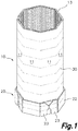
- the present invention relates to a container formed by a tubular polygonal body 10 attached to a body 20, both made of corrugated cardboard.
- Corrugated cardboard is that cardboard made from a combination of smooth sheets 15 attached with adhesive to corrugated sheets 16, i.e., folded sheets forming a corrugation in the form of parallel channels.
- the result is a cost-effective and recyclable material that is furthermore lightweight and strong.
- Single-faced corrugated cardboard 14 is that formed by only one smooth sheet 15 adhered to one corrugated sheet 16, resulting in a material that has certain compressive strength and bending strength in the direction of the corrugation but is flexible in the other direction, therefore being a rollable material. This allows producing strips of corrugated cardboard 19 of a significant length and storing and transporting them in an easy and cost-effective manner in a rolled-up position.
- Stiff corrugated cardboard 24 is that corrugated cardboard formed by at least two smooth sheets 15 with at least one interposed corrugated sheet 16 adhered to the two smooth sheets 15, forming double-faced corrugated cardboard.
- a triple-faced corrugated cardboard, quadruple-faced corrugated cardboard, etc., is obtained by adding more smooth sheets 15 and more corrugated sheets 16 to the assembly.
- stiff corrugated cardboard 24 is stiff and resistant to bending and compression in all directions, forming flat panels.
- the tubular polygonal body 10 of the proposed container is a body in the shape of a hollow tube, having two open ends and a polygonal section defined by an even number of substantially flat faces 11 numbering more than four, for example six or eight faces 11, each comprised between two corner areas 12.
- the tubular polygonal body is produced with a strip of corrugated cardboard 19 that is single-faced corrugated cardboard 14, with the aforementioned advantages in terms of storage and handling. This reduces logistics costs as well as the waste for the production of tubular polygonal bodies 10 in comparison with other solutions based on stiff corrugated cardboard 24.
- Two adjacent faces 11 form an angle with respect to one another in the mentioned corner area 12.
- the angle that said faces form with respect to one another is an obtuse angle, preferably greater than 120°, in addition to obtaining a tubular body with a greater strength against the hydrostatic pressure that a liquid, pasty, or granular product stored therein may exert on said tubular polygonal body 10 in comparison with a container with four sides.
- the proposed tubular polygonal body 10 is formed by a strip of single-faced corrugated cardboard 14 rolled up at least two times around a hollow polygonal interior and adhered to itself, obtaining a tubular polygonal body 10 defined by a multilayer wall 13 surrounding a hollow interior.
- Said multilayer wall 13 of the container can be produced with a number of layers adapted to the strength or economic needs of each case, i.e., tubular polygonal bodies 10 of different strengths and prices can be produced by simply superimposing more or fewer layers of single-faced corrugated cardboard layer 14 that is rolled up. This allows obtaining a wide variety of containers with different performances and prices with the same materials and processes.
- the base body 20 will be formed by a stiff corrugated cardboard 24 which offers the strength required for this use.
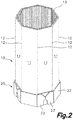
- the proposed base body 20 is formed by a polygonal bottom 21 surrounded by a polygonal base wall perpendicular to said polygonal bottom 21. Both the polygonal bottom 21 and the polygonal base wall will have a number of sides equal to the number of faces of the tubular polygonal body 10, and their size and proportion will be complementary to those of the tubular polygonal body 10.
- the polygonal bottom 21 is placed coinciding with one of the open ends of the tubular polygonal body 10, with the polygonal base wall surrounding and contacting a lower end portion of the multilayer wall 13 of the tubular polygonal body 10 adjacent to said open end.
- the base body 20 will be formed from a cut and folded single base panel 18 of stiff corrugated cardboard 24 to form the described base body 20, as shown in Figures 6 and 7 .
- each face of the polygonal base wall is formed by lateral parts 22 extending from one of the sides of the polygonal bottom 21, defining between both a fold line, and each lateral part 22 of the polygonal base wall is attached to the other adjacent lateral parts after the folding thereof by means of flaps 23 which are attached in continuity by means of fold lines to some of said lateral parts 22, the polygonal base wall as a whole forming a closed envelopment around the end of the tubular polygonal body 10 which allows reinforcing said end.
- Figures 7 to 10 show different embodiments in which lines of glue parallel to one another have been applied on different areas of the stiff corrugated cardboard 24.
- the application of all the lines of glue parallel to one another allows said lines of glue to be applied by means of a bridge of applicators, moving the stiff corrugated cardboard 24 below said bridge in a forward movement direction parallel to the lines of glue to be deposited.
- the individual control of each glue applicator allows the precise deposition thereof in the desired areas.
- the lines of glue applied on the flaps 23 will attach the inner surface of said flaps 23 where the lines of glue have been deposited to the outer surface of the polygonal base wall, thereby forming the base body 20.
- the single-faced corrugated cardboard 14 forming the tubular polygonal body 10 will be placed with the corrugation thereof being located in a direction perpendicular to the polygonal bottom 21 of the base body 20, as can be seen Figures 1 , 2 , and 4 , i.e., parallel to the folds of the corner areas 12.
- this arrangement of the single-faced corrugated cardboard 14 allows, during the formation of the tubular polygonal body 10, the strip of single-faced corrugated cardboard 14 to adapt to the polygonal shape of the tubular polygonal body 10 without requiring the flattening or cutting of said single-faced corrugated cardboard 14 in the corner areas 12, as it will only be necessary to adapt same to the curvature of the corner area 12.
- This direction of the lines of glue 30 allows the continuous application thereof on the single-faced corrugated cardboard 14 while it is being rolled up, resulting in a very quick and simple, and therefore low-cost, production process, while at the same time obtaining optimal strength, by assuring that each of the undulations of the corrugated sheet 16 of a layer of the multilayer wall 13 has adhesion points with the smooth sheet 15 on which said corrugated sheet 16 is superimposed, corresponding to another portion of the same single-faced corrugated cardboard 14 forming another layer of the multilayer wall 13 of the tubular polygonal body 10.
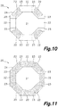
- the tubular polygonal body 10 is octagonal, and therefore consists of eight substantially flat faces 11 and eight corner areas 12 located between the faces 11.
- all the substantially flat faces 11 are of the same horizontal length, so they form a regular octagon, with the angle existing between two contiguous faces 11 being 135°.
- the number of faces 11 of the tubular polygonal body 10 can be another even number of more than four but other than eight, for example six, forming angles of 120° in the corner areas 12, ten forming angles of 144°, or twelve forming angles of 150°.
- the angle that the contiguous faces 11 form with respect to one another will preferably be greater than 120°.
- the angle of the corner areas 12 will be an obtuse angle which will require an angle of curvature of the single-faced corrugated cardboard 14 that is rather wide, and therefore readily applicable without damaging the single-faced corrugated cardboard 14.
- This construction allows the thickness of the multilayer wall 13 of the tubular polygonal body 10 to be a constant thickness, both in the substantially flat faces 11 and in the corner areas 12. Furthermore, in the preferred embodiment the outer surface of the corner areas 12 will be rounded, even if the inner surface of the corner area defines an edge, as a result of that increased radius of curvature with each additional layer of the multilayer wall 13, a solution shown in Figures 1 and 5 .
- each layer of the multilayer wall 13 can define an edge in the corresponding corner area 12, causing said edge to be visible even on the outer surface of the corner area 12; however, this solution is less favorable as it requires the precise folding of the single-faced corrugated cardboard 14 coinciding with each corner area 12, with the additional problem of the diameter of the multilayer wall 13 varying slightly as layers are added thereto, increasing the length of each face 11, which complicates the production of this embodiment.
- the multilayer wall consists of three layers along its entire perimeter, with only a small overlap of four layers coinciding with the start and end of the strip of single-faced corrugated cardboard 14.
- a cover body 40 identical to the base body 20, can be fitted to the end of the tubular polygonal body 10 opposite the end attached to the base body 20.
- a plastic bag inside the container the maximum diameter of which is equal to or greater than the maximum inner cross-section of the tubular polygonal body 10 is also contemplated. This allows storing and preserving a product, even liquid or wet product, in the proposed container, with the hydrostatic pressure produced by the stored material being transmitted to the multilayer wall 13 and not to the plastic bag.
- the tubular polygonal body 10 is formed by a strip of corrugated cardboard 19 which is a stiff double-faced corrugated cardboard 24.
- the stiff double-faced corrugated cardboard 24 is in the form of a stiff panel, where the strip of corrugated cardboard can be formed by a single duly folded stiff panel, forming the tubular polygonal body 10, or where the strip of corrugated cardboard can be formed by several stiff panels arranged in succession, one after another, with the respective adjacent ends.
- a second aspect of the present invention relates to a method of forming containers.
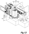
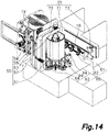
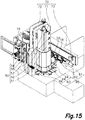
- the different steps of the proposed method can be seen in Figures 12 to 16 .
- the method consists of forming a tubular polygonal body 10 based on rolling up and adhering a strip of corrugated cardboard 19 to itself by means of a polygonal rotary drum 51 to which an end edge 17 of the strip of corrugated cardboard 19 is fixed, allowing the rotation of the polygonal rotary drum 51 to pull the strip of corrugated cardboard 19 in a forward movement direction D1 while at the same time rolling said strip of corrugated cardboard 19 around same.
- the end edge 17 will be parallel to the corrugation of the strip of corrugated cardboard 19, and parallel to the axis of rotation of the polygonal rotary drum 51.
- the forward movement direction D1 will be transverse to said direction of the corrugation and also transverse to the mentioned axis of rotation.
- the strip of corrugated cardboard 19 moved in the forward movement direction D1 passes through an applicator device 55 for lines of glue which deposits multiple parallel lines of glue on one of the faces of the strip of corrugated cardboard 19 before it is rolled around the polygonal rotary drum 51.
- an applicator device 55 for lines of glue which deposits multiple parallel lines of glue on one of the faces of the strip of corrugated cardboard 19 before it is rolled around the polygonal rotary drum 51.
- the applicator device 55 for lines of glue will be configured to apply lines of glue only on those parts of the strip of corrugated cardboard that will be superimposed on other parts of the strip of corrugated cardboard 19 when being rolled.
- Said lines of glue can be applied either on one face or on the other face of the strip of corrugated cardboard 19.
- a base panel 18 made of stiff double-faced corrugated cardboard 24 which has been cut is then supplied, defining a polygonal bottom 21 of the same shape and size as the layout of the tubular polygonal body 10, surrounded by lateral parts 22 connected to the edges of the polygonal bottom 21 by means of fold lines.
- Some of the mentioned lateral parts 22 will have flaps 23 attached by means of fold lines to some of the side edges thereof.
- Parallel lines of glue will be arranged on at least some of the lateral parts 22 and/or of the flaps 23 of the base panel 18 and said base panel 18 will then be placed centered with and adjacent to the lower end portion of the tubular polygonal body 10 formed around the polygonal rotary drum 51, closing the opening of the tubular polygonal body 10 with the polygonal bottom 21.
- the lateral parts 22 of the base panel 18 are then folded to form a 90° angle with respect to the polygonal bottom 21, said lateral parts 22 being arranged around the lower end portion of the tubular polygonal body 10 surrounding it.
- the flaps 23 will also be folded in the same operation so that they are superimposed on the lateral parts 22, forming a polygonal base wall with continuous envelopment around the tubular polygonal body 10.
- the resulting container can be extracted from the forming machine by means of a delivery device which conveys same to a delivery area of the forming machine.
- the last aspect of the proposed invention is the container forming machine.
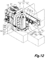
- the proposed machine has a tubular polygonal body forming station 50, in charge of forming a tubular polygonal body 10 from a strip of corrugated cardboard 19, a base body forming station 60 in charge of forming a base body 60 and connecting it to the lower end portion of the formed tubular polygonal body 10, and finally an extraction station 70 intended for extracting the formed polygonal containers from the inside of the forming machine, allowing the formation of a new container.
- the tubular polygonal body forming station 50 comprises a storage area for the strip of corrugated cardboard, a polygonal rotary drum 51, and a supplier device 54 for the strip of corrugated cardboard 19 conveying the strip of corrugated cardboard 19 from the storage area to the polygonal rotary drum 51 by means of the movement thereof in the forward movement direction D1.
- the supplier device 54 for the strip of corrugated cardboard 19 consists of a carriage horizontally movable along a horizontal guide parallel to the forward movement direction D1 and driven by an actuator which is proposed to be a motor in this case.
- Said carriage is provided with vacuum suction cups connected to a vacuum generator and oriented to be superimposed on a face of the strip of corrugated cardboard 19, securing it by suction and allowing it to be pulled when the carriage moves in the forward movement direction D1.
- the tubular polygonal body forming station 50 is completed with an applicator device 55 for lines of glue and a releasable fixing device 52 integrated in the polygonal rotary drum 51 intended for retaining an end edge 17 of the strip of corrugated cardboard 19 while the polygonal rotary drum 51 rotates on its axis of rotation, rolling the strip of corrugated cardboard 19 around same.
- the strip of corrugated cardboard 19 is single-faced corrugated cardboard 14 rolled on a drum
- the supplier device is a carriage provided with suction cups linearly movable in the forward movement direction D1 to grip a portion of the strip of corrugated cardboard adjacent to the end edge 17 thereof and convey same in the forward movement direction D1 until locating said end edge 17 on the polygonal rotary drum 51 where the releasable fixing device 52 fixes said end edge 17 on the polygonal rotary drum 51, said end edge 17 being parallel to the axis of rotation of the polygonal rotary drum 51.
- the releasable fixing device 52 consists of retractable fingers 80 which are superimposed on the outer face of a vertical panel 74 forming the polygonal rotary drum 51, retaining the end edge 17. To release said end edge 17, the mentioned fingers are concealed inside the polygonal rotary drum 51.
- said releasable fixing device 52 comprises a retractable finger 80 and a finger actuator 81, for example, a piston or a motor, actuating the pivoting movement of said retractable finger 80.
- the finger actuator 81 is a pneumatic cylinder supported in an articulated manner by means of a vertical shaft in an inner structure of the polygonal rotary drum 51.
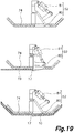
- the finger actuator 81 drives a part, also articulated with respect to the inner structure of the polygonal rotary drum 51, at the end of which there is located the retractable finger 80, causing the rotation thereof and the movement of the retractable finger 80 between an initial standby position, in which the retractable finger 80 is housed inside the polygonal rotary drum 51, and an active position in which the retractable finger 80 projects from the polygonal rotary drum 51, for example through a window made in said vertical panel 74, being partially superimposed on an outer face of one of the vertical panels 74 of said polygonal rotary drum 51, retaining an end edge 17 of a strip of corrugated cardboard 19.
- Figure 19 shows this embodiment in three different positions, a first standby position, a second active position, and a third standby position after the formation of a tubular polygonal body 10.
- Figure 20 shows an alternative embodiment of the releasable fixing device 52 which, in this example, comprises vacuum suction cups 82 connected to a vacuum generator and supported in the inner structure of the polygonal rotary drum 51.
- the suction cups 82 are housed inside the polygonal rotary drum 51, but their active part in which suction occurs is oriented towards and accessible from the outside of the polygonal rotary drum 51 through windows provided in at least one of the vertical panels 74 of the polygonal rotary drum 51.
- the suction cups 82 In the active position, the suction cups 82 will be coplanar or project partially from the outer face of the polygonal rotary drum 51 on which the tubular polygonal body 10 is formed. By supporting a portion of the strip of corrugated cardboard 19 adjacent to the end edge 17 on the suction cups, it will be fixed by the action of the vacuum suction cups 82.
- the releasable fixing device 52 further comprises a suction cup actuator 83 in the shape of an extendable rod on which the suction cups 82 are fixed, allowing the movement of the suction cups 82 in a radial direction with respect to the polygonal rotary drum 51 so that they project partially from the polygonal rotary drum 51 or so that they are completely retracted into the drum.
- a suction cup actuator 83 in the shape of an extendable rod on which the suction cups 82 are fixed, allowing the movement of the suction cups 82 in a radial direction with respect to the polygonal rotary drum 51 so that they project partially from the polygonal rotary drum 51 or so that they are completely retracted into the drum.
- the polygonal rotary drum 51 of the polygonal tubular body forming station 50 is arranged with its axis of rotation being vertical, supported at its upper end by means of an arm 72, the polygonal rotary drum 51 being vertically suspended above the folder device 63 and the assembly position but separated from same by a supply passage in the form of a gap between the lower end of the polygonal rotary drum 51 and the folder device 63 through which a base panel 18 can be introduced in a supply direction D2 for supplying base panels from a storage area to the assembly position by means of the supplier device 61 for base panels.
- a driving member 53 will actuate the polygonal rotary drum 51 to cause the rotation thereof around the mentioned vertical axis, rolling the strip of corrugated cardboard 19 around same.
- a hold-down member 57 may collaborate with the polygonal rotary drum 51 to press the strip of corrugated cardboard 19 against the mentioned polygonal rotary drum 51, achieving better adhesion of the layers forming the tubular polygonal body 10, for example in the shown embodiments the hold-down member 57 consists of a roller parallel to the axis of rotation of the polygonal rotary drum 51 located at the end of a pivoting arm.
- Said hold-down member 57 can swing, modifying its distance with respect to the center of the polygonal rotary drum 51, and it can therefore be adapted to the polygonal contour thereof, to the increasing thickness of the tubular polygonal body 10 as it is formed, or separated from the same to allow coupling the end edge 17 of a new strip of corrugated cardboard 19 to the polygonal rotary drum 51 or to release a recently formed tubular polygonal body 10 from the polygonal rotary drum 51.
- a retractable shaft 56 can traverse the supply passage, temporarily interrupting same for fixing the center of the lower end of the polygonal rotary drum 51 to a lower chassis, allowing the rotation thereof, as can be seen Figure 18 .
- Figure 18 shows said retractable shaft 56 according to an envisaged embodiment, whereby the retractable shaft 56 is connected to a retractable shaft actuator 58 in the form of a piston which allows moving said retractable shaft 56 vertically between a standby position, in which is it completely located below the mentioned supply passage and decoupled from the polygonal rotary drum 51, and an active position in which the retractable shaft 56 traverses the mentioned supply passage and is tightly inserted in a complementary housing envisaged in the center of the lower end portion of the polygonal rotary drum 51, aligned with the axis of rotation thereof.
- a retractable shaft actuator 58 in the form of a piston which allows moving said retractable shaft 56 vertically between a standby position, in which is it completely located below the mentioned supply passage and decoupled from the polygonal rotary drum 51, and an active position in which the retractable shaft 56 traverses the mentioned supply passage and is tightly inserted in a complementary housing envisaged in the center of the lower end portion of the polygonal rotary drum 51, aligned with the
- the coupling between the retractable shaft 56 and the polygonal rotary drum 51 will allow rotation of the polygonal rotary drum 51, so it is proposed to include, for example, bearings between the retractable shaft 56 and the retractable shaft actuator or between the retractable shaft 56 and the housing of the polygonal rotary drum 51. It is even contemplated that the housing is supported with the rest of the polygonal rotary drum through bearings to allow the rotation thereof.
- the retractable shaft 56 and its retractable shaft actuator can be housed inside the polygonal rotary drum 51, with the retractable shaft 56 being moved upwards to be housed in a housing envisaged in the lower chassis located below the base panel supply passage.
- the polygonal rotary drum 51 is formed by an inner structure attached to the vertical rotating shaft, on which multiple vertical panels 74 defining the polygonal envelopment of the polygonal rotary drum 51 are fixed.
- the machine is envisaged for the formation of octagonal containers, so the polygonal rotary drum 51 defines eight vertical faces in its envelopment.
- the polygonal rotary drum 51 consists of four panels located in four quadrants of the polygonal rotary drum 51, each panel including two inclined or beveled ends, each panel therefore defining an outer face of the envelopment of the polygonal rotary drum 51 and also two other adjacent faces in a partial manner.
- the polygonal tubular body forming station 50 is completed with the applicator device 55 for lines of glue consisting of a bridge supporting multiple applicators of lines of glue.
- the supplier device 54 for the strip of corrugated cardboard 19 conveys said strip of corrugated cardboard 19 in a vertical position in the forward movement direction D1, the strip of corrugated cardboard 19 passing in front of the bridge forming the applicator device 55 for lines of glue, said bridge therefore being in a vertical position.
- said applicators deposit lines of glue parallel to the forward movement direction D1 on a face of the strip of corrugated cardboard 19.
- the applicator device 55 of lines of glue will be coordinated with the supplier device 54 for depositing lines of glue only in those areas of the strip of corrugated cardboard 19 intended for being superimposed with other areas of the strip of corrugated cardboard 19 after being rolled around the polygonal rotary drum 51.
- the base body forming station 60 comprises a folder device 63, a storage area for base panels 18, a supplier device 61 for base panels 18 conveying the base panels 18 from the storage area to the folder device 63 by moving them in a supply direction D2 through a supply passage defined between the lower end portion of the polygonal rotary drum 51 and the folder device 63 located below same.
- the base body forming station 60 further comprises an applicator device 62 for lines of glue located above the supply passage and configured for applying lines of glue on discrete areas of the base panels 18 conveyed through the supply passage, said lines of glue being parallel to the supply direction D2.
- the base panels 18 are conveyed in a horizontal position, the supply direction D2 also being horizontal.
- the applicator device 62 for lines of glue consists of a bridge located above the supply passage, on which multiple applicators of lines of glue are supported superimposed on the supply passage.
- the folder device 63 is located right below the polygonal rotary drum 51 and consists of a plurality of folder units 64 arranged like petals surrounding the base of the polygonal rotary drum 51 below the base panel supply passage.
- a folder device 63 which, in the shown embodiment relating to an octagonal container forming machine, consists of eight folder units 64 supported in the lower chassis of the machine and radially arranged below and around the lower end portion of the polygonal rotary drum 51, below the assembly position where the base panels 18 are placed before folding.
- Each folder unit 64 comprises a pivoting arm 65 articulated with respect to the lower chassis around a horizontal axis parallel to and vertically aligned with one of the faces of the polygonal rotary drum 51 positioned in the holding position, such that the rotation of the pivoting arm 65 allows said pivoting arm 65 to be arranged parallel to and facing a lower end portion of a face of the polygonal rotary drum 51 located in the holding position.
- a folder unit actuator 66 which is a piston in this embodiment, actuates each pivoting arm 65 to move it from a standby position, in which it is located below the supply passage for base panels 18 and below the assembly position, therefore allowing the supplier device 61 for base panels 18 to supply a base panel 18 through said supply passage until placing it in the assembly position, to a folding position in which each pivoting arm 65 is upright and facing a lower end portion of one of the outer faces of the polygonal rotary drum 51 in the holding position, causing parts of the base panel 18 located in the assembly position to be folded and pressed against the outer surface of the lower end portion of a tubular polygonal body 10 formed around the polygonal rotary drum 51, adhering them.
- the machine is completed with an extraction station 70 intended for extracting the formed containers from inside the machine, therefore allowing the formation of a new container.
- the polygonal rotary drum 51 For the extraction of a recently formed container, the polygonal rotary drum 51 must be extracted from the inside of the tubular polygonal body 10 formed around same. To that end, it is proposed to provide the polygonal rotary drum 51 with a retraction device 71 envisaged for reducing the cross-section of the polygonal rotary drum 51, thereby having clearance inside the tubular polygonal body 10, facilitating the extraction thereof.
- Figure 18 shows an embodiment of the retraction device 71 whereby one or more of the vertical panels 74 defining the envelopment of the polygonal rotary drum 51 described above are attached to the central structure through multiple pivoting arms 75, with each pivoting arm 75 being articulated around horizontal shafts.
- each panel of the polygonal rotary drum 41 moves vertically, modifying its distance with respect to the central structure of the polygonal rotary drum 51 and therefore modifying the cross-section of the polygonal rotary drum 51.
- a retraction actuator 76 which consists of a piston in this case controls the movement of each vertical panel 74 determining its position at all times.
- the extraction station 70 further comprises an extractor device 72 moving the polygonal rotary drum 51 in a vertical direction parallel to its axis of rotation, allowing the extraction thereof from the inside of the formed container.
- the polygonal rotary drum 51 is suspended from an arm at its lower end. Said arm is connected in a sliding manner to a vertical guide and an arm actuator which causes the movement of said arm along the vertical guide, lifting the polygonal rotary drum 51.
- the extraction station 70 additionally comprises a container conveyor 73 envisaged for moving the formed containers after the extraction of the polygonal rotary drum 51 from the inside thereof to an extraction area of the machine, preferably in a horizontal direction.
- the container conveyor consists of a carriage horizontally movable along a horizontal guide.
- the carriage includes vacuum suction cups connected to a vacuum generator, the carriage being located such that, at one end of its path, the suction cups are in contact with the outer face of the formed container, and at the other end of its path, it is adjacent to the extraction area.
- the suction cups or the carriage can be connected to an actuator which causes the movement thereof in a horizontal direction transverse to the horizontal carriage guide, allowing the suction cups to be moved closer to or away from the formed container.
Landscapes
- Engineering & Computer Science (AREA)
- Mechanical Engineering (AREA)
- Making Paper Articles (AREA)
- Cartons (AREA)
Claims (18)
- Verstärkter vieleckiger Behälter aus geklebtem Welllaminat, Folgendes umfassend:• einen rohrförmigen vieleckigen Körper (10) mit einer geraden Anzahl von ebenen Flächen (11), die mehr als vier sind, die zwischen Eckbereichen (12) definiert sind, wobei der rohrförmige vieleckige Körper (10) durch einen Streifen aus Wellpappe (19) gebildet wird, der mindestens teilweise mit sich selbst überlappt und auf sich selbst aufgeklebt ist;• einen Basiskörper (20), der durch eine Basisplatte definiert ist, die durch geschnittene und gefaltete steife doppelseitige Wellpappe (24) gebildet ist, die einen vieleckigen Boden (21) und eine vieleckige Basiswand definiert, die den vieleckigen Boden (21) umgibt und senkrecht dazu steht, wobei die vieleckige Basiswand die gleiche Anzahl von Seiten wie der rohrförmige vieleckige Körper (10) aufweist und eine innere Oberfläche jeder Seite der vieleckigen Basiswand mit einem unteren Endabschnitt einer äußeren Oberfläche der Flächen (11) des rohrförmigen vieleckigen Körpers (10) überlappt und daran aufgeklebt ist, wobei der Basiskörper (20) um einen Endabschnitt des rohrförmigen vieleckigen Körpers (10) herum befestigt wird;wobei die Wellpappe des rohrförmigen vieleckigen Körpers (10) eine Wellplatte (16) einschließt, die Kanäle senkrecht zum vieleckigen Boden (21) des Basiskörpers (20) bildet;dadurch gekennzeichnet, dassder Streifen aus Wellpappe (19) des rohrförmigen vieleckigen Körpers (10) mindestens zwei volle Umdrehungen aufgerollt ist und mittels Kleberlinien (30) an sich selbst geklebt ist, die quer zu den Kanälen der Wellplatte (16) verlaufen, wobei eine mehrschichtige Wand (13) gebildet wird.
- Verstärkter vieleckiger Behälter gemäß Anspruch 1, wobei der Endabschnitt des rohrförmigen vieleckigen Körpers (10), um den die vieleckige Basiswand angeklebt und überlappt ist, mindestens einen Teil der erwähnten Kleberlinien (30) einschließt, die den Streifen aus Wellpappe (19) an sich selbst befestigen.
- Verstärkter vieleckiger Behälter gemäß Anspruch 1 oder 2, wobei die Wellpappe, die den rohrförmigen vieleckigen Körper (10) bildet, eine einseitige Wellpappe (14) ist, die mit einer glatten Platte (15) und einer Wellplatte (16) versehen ist.
- Verstärkter vieleckiger Behälter gemäß Anspruch 1 oder 2, wobei der Streifen aus Wellpappe (19), der den rohrförmigen vieleckigen Körper (10) bildet, eine Platte oder mehrere aufeinanderfolgende Platten mit benachbarten Enden aus steifer doppelseitiger Wellpappe ist, wobei die Eckbereiche durch Falten des Streifens aus Wellpappe (19) gebildet werden.
- Verstärkter vieleckiger Behälter gemäß einem der vorhergehenden Ansprüche, wobei ein Basiskörper (20) durch eine Basisplatte definiert wird, die aus steifer, dreiseitiger Wellpappe (24) gebildet wird.
- Verstärkter vieleckiger Behälter gemäß einem der vorhergehenden Ansprüche, wobei die Länge des Streifens aus Wellpappe (19) gleich einem Mehrfachen des Umfangs des rohrförmigen vieleckigen Körpers (10) zuzüglich einer Überlappungsfläche ist, die gleich oder kleiner als die Länge einer Fläche (11) des rohrförmigen vieleckigen Körpers (10) ist oder im Bereich zwischen 5 cm und 15 cm liegt.
- Verstärkter vieleckiger Behälter gemäß einem der vorhergehenden Ansprüche, wobei die Stärke der mehrschichtigen Wand (13) auf den ebenen Flächen (11) gleich der Stärke in den Eckbereichen (12) ist.
- Verstärkter vieleckiger Behälter gemäß einem der vorhergehenden Ansprüche, wobei die Seiten der vieleckigen Basiswand durch Seitenteile (22) gebildet werden, die mit dem vieleckigen Boden (21) mittels Faltlinien verbunden sind und mittels Klappen (23) aneinander befestigt sind, die mit mindestens einigen der Seitenteile (22) mittels Faltlinien verbunden sind und mit benachbarten Seitenteilen (22) der vieleckigen Basiswand mittels zueinander paralleler Kleberlinien in der ebenen Anordnung des Basiskörpers (20) verklebt sind, wobei eine geschlossene Umhüllung gebildet wird, die den Endabschnitt des rohrförmigen vieleckigen Körpers (10) vollständig umgibt.
- Verstärkter vieleckiger Behälter gemäß Anspruch 8, wobei die innere Oberfläche der vieleckigen Basiswand an der äußeren Oberfläche des Endabschnitts des rohrförmigen Körpers (10) mittels zueinander paralleler Kleberlinien in der ebenen Anordnung des Basiskörpers (20) und die parallel zu den Kleberlinien sind, die die Klappen (23) an den Seitenteilen (22) befestigen, befestigt ist.
- Verfahren zum Bilden von verstärkten vieleckigen Behältern, das Folgendes umfasst:• Bilden eines rohrförmigen vieleckigen Körpers aus Wellpappe;• Zuleiten von steifer doppelseitiger Wellpappe (24), die durch eine Basisplatte (18) definiert ist, die durch einen vieleckigen Boden (21) gebildet wird, der von Seitenteilen (22) und Klappen (23) umgeben ist, wobei eine vieleckige Basiswand mit der gleichen Anzahl von Seiten wie der rohrförmige vieleckige Körper (10) gebildet wird, wobei die Seitenteile (22) mit dem vieleckigen Boden (21) durch Faltlinien verbunden sind und die Klappen (23) mit den Seitenteilen (22) durch Faltlinien verbunden sind;• Auftragen von zueinander paralleler Kleberlinien auf Bereiche der Basisplatte (18);• Positionieren der Basisplatte (18) benachbart zu und zentriert mit einem unteren Endabschnitt des rohrförmigen vieleckigen Körpers (10), wobei der untere Endabschnitt mit dem vieleckigen Boden (21) geschlossen wird;• Falten der Seitenteile (22) und Klappen (23) der Basisplatte (18) entlang der Faltlinien durch Drücken derselben gegen eine äußere Oberfläche des unteren Endabschnitts des rohrförmigen vieleckigen Körpers (10), wobei die vieleckige Basiswand um den Endabschnitt des rohrförmigen vieleckigen Körpers (10) herum gebildet und angeklebt wird;dadurch gekennzeichnet, dass der Schritt des Bildens des rohrförmigen vieleckigen Körpers (10) Folgendes umfasst:• Festhalten einer Endkante (17) eines Streifens aus Wellpappe (19) auf einer vieleckigen Drehtrommel (51) mit einer geraden Anzahl von ebenen Facetten, die mehr als vier sind, wobei der Kanal der in dem Streifen aus Wellpappe (19) eingeschlossenen Wellplatte (16) parallel zu einer Drehachse der vieleckigen Drehtrommel (51) ist;• Auftragen von zueinander paralleler Kleberlinien, die quer zu den Kanälen auf einer Fläche des Streifens aus Wellpappe (19) verlaufen;• Zuführen des Streifens aus Wellpappe (19) in einer Vorschubrichtung quer zu den Kanälen bei gleichzeitigem Drehen der vieleckigen Drehtrommel (51) um die Drehachse um mindestens zwei volle Umdrehungen, wobei das Rollen des Streifens aus Wellpappe (19) um dieselbe bewirkt wird, wobei ein rohrförmiger vieleckiger Körper (10) mit einer mehrschichtigen Wand (13) gebildet wird;• Lösen der Endkante (17) und Entnehmen des rohrförmigen vieleckigen Körpers (10) aus der vieleckigen Drehtrommel (51).
- Verfahren gemäß Anspruch 10, wobei die Bildung und das Aufkleben der vieleckigen Basiswand um den Endabschnitt des rohrförmigen vieleckigen Körpers (10) vor dem Entnehmen des rohrförmigen vieleckigen Körpers (10) aus der vieleckigen Drehtrommel (51) durchgeführt werden.
- Verfahren gemäß Anspruch 11, wobei die Basisplatte in Bezug auf den rohrförmigen vieleckigen Körper (10) durch eine Bewegung in einer Richtung senkrecht zur Drehachse der vieleckigen Drehtrommel (51) und parallel zur Richtung der Kleberlinien positioniert wird, die auf die Basisplatte (18) aufgetragen werden, während sie sich bewegt.
- Verfahren gemäß Anspruch 10, 11 oder 12, wobei die auf den Streifen aus Wellpappe (19) aufgetragenen Kleberlinien gleichzeitig mit dem Rollen des Streifens aus Wellpappe (19) aufgetragen werden, wobei die Kleberlinien parallel zur Vorschubrichtung verlaufen.
- Verfahren gemäß Anspruch 10, 11, 12 oder 13, wobei die Kleberlinien Kaltkleberlinien und Heißkleberlinien kombinieren.
- Maschine zum Bilden von verstärkten vieleckigen Behältern, Folgendes einschließend:eine Bildungsstation (50) von rohrförmigen vieleckigen Körpern, die zum Halten eines rohrförmigen vieleckigen Körpers (10) in einer Halteposition ausgebildet ist;eine Basiskörper-Bildungsstation (60), Folgendes umfassend:• eine Zuführvorrichtung (61) für Basisplatten (18), die zum Zuführen von Basisplatten (18) in einer Zuführrichtung (D2) durch einen Zuführdurchgang zu einer Montageposition ausgebildet ist, die benachbart zu einem unteren Endabschnitt eines rohrförmigen vieleckigen Körpers (10) liegt, der sich in der Halteposition befindet;• eine Auftrag-Vorrichtung (62) für Kleberlinien, die zum Auftragen von Kleberlinien auf eine Basisplatte ausgebildet ist, während diese sich in der Zuführrichtung (D2) bewegt;• eine Faltvorrichtung (63), die aus mehreren Falteinheiten (64) besteht, die der Montageposition zugewandt angeordnet sind, wobei jede zwischen einer Bereitschaftsposition, in der sie weder den Zuführdurchgang noch die Montageposition beeinflussen, und einer Faltposition, in der die Falteinheiten (64) die Montageposition beeinflussen und um die Halteposition herum angeordnet sind, beweglich ist, wobei das Falten von Teilen einer in der Montageposition befindlichen Basisplatte (18) bewirkt wird, indem sie gegen einen unteren Endabschnitt eines in der Halteposition befindlichen rohrförmigen vieleckigen Körpers (10) gedrückt werden;dadurch gekennzeichnet, dass die Bildungsstation (50) von rohrförmigen vieleckigen Körpern Folgendes umfasst:• eine vieleckige Drehtrommel (51), die eine gerade Anzahl von ebenen Facetten definiert, die mehr als vier sind und die Halteposition um dieselbe herum bestimmen, und die eine lösbare Fixiervorrichtung (52) zum Fixieren einer Endkante (17) eines Streifens aus Wellpappe (19) einschließt, wobei die vieleckige Drehtrommel (51) mit einer freitragenden Drehwelle verbunden ist, die mittels eines Antriebselements (53) betrieben wird;• eine Zuführvorrichtung (54) für den Streifen aus Wellpappe (19), die zum Bewegen des Streifens aus Wellpappe (19) in einer Vorschubrichtung (D1) quer zur Drehachse der vieleckigen Drehtrommel (51) ausgebildet ist;• eine Auftrag-Vorrichtung (55) für Kleberlinien, die aus einer Brücke von Kleberlinien-Auftragseinrichtungen besteht, die so ausgebildet sind, dass sie Kleberlinien auf eine Fläche des Streifens aus Wellpappe (19) auftragen, während er sich in die Vorschubrichtung (D1) bewegt;und dass die Maschine weiterhin eine Entnahmestation (70) von gebildeten vieleckigen Behältern einschließt,Folgendes umfassend:• eine Retraktionsvorrichtung (71) der vieleckigen Drehtrommel (51), die zur Verringerung ihres Querschnitts ausgebildet ist;• eine Entnahmevorrichtung (72), die zum Bewegen der vieleckigen Drehtrommel (51) in einer Richtung parallel zu ihrer Drehachse für die Entnahme davon aus dem Inneren des gebildeten Behälters ausgebildet ist.
- Maschine gemäß Anspruch 15, wobei jede Auftrag-Vorrichtung für Kleberlinien der Bildungsstation von rohrförmigen vieleckigen Körpern und/oder der Basiskörper-Bildungsstation eine Kombination von Kaltkleber- und Heißkleber-Auftragseinrichtungen einschließt.
- Maschine gemäß Anspruch 15 oder 16, die ferner ein Niederhalteglied (57) umfasst, das am Ende eines Schwenkarms angeordnet ist, der den Abstand zwischen dem Niederhalteglied (57) und dem Zentrum der vieleckigen Drehtrommel (51) verändert, zwischen einer Druckposition, in der das Niederhalteglied (57) den Streifen aus Wellpappe (19) gegen die vieleckige Drehtrommel (51) drückt, wobei die Position des Niederhalteglieds (57) an die vieleckige Kontur der vieleckigen Drehtrommel (51) bei deren Drehung angepasst wird, und einer von dem Streifen aus Wellpappe (19) und der vieleckigen Drehtrommel (51) getrennten Bereitschaftsposition.
- Maschine gemäß Anspruch 15, 16 oder 17, die ferner eine einziehbare Welle (56) umfasst, die koaxial zum Zentrum der vieleckigen Drehtrommel (51) liegt, bewegbar mittels eines einziehbaren Wellenaktuators (58) zwischen einer gekoppelten Position, in der das freitragende Ende der vieleckigen Drehtrommel (51) drehbar mit einem Stützrahmen verbunden wird, und einer entkoppelten Position, in der das freitragende Ende der vieleckigen Drehtrommel (51) von dem erwähnten Rahmen getrennt wird.
Applications Claiming Priority (4)
| Application Number | Priority Date | Filing Date | Title |
|---|---|---|---|
| ES201830052A ES2666269A1 (es) | 2018-01-18 | 2018-01-18 | Método y máquina para la formación de cuerpos reforzados de material laminar, y cuerpo reforzado obtenido |
| ES201830796U ES1215607Y (es) | 2018-01-18 | 2018-05-30 | Bidon poligonal reforzado de material laminar corrugado encolado |
| ES201830798U ES1215608Y (es) | 2018-01-18 | 2018-05-30 | Bidon poligonal reforzado de material laminar corrugado |
| PCT/ES2018/070832 WO2019141887A1 (es) | 2018-01-18 | 2018-12-24 | Bidón poligonal reforzado de material laminar corrugado encolado, método de fabricación y máquina de formación del mismo |
Publications (3)
| Publication Number | Publication Date |
|---|---|
| EP3616896A1 EP3616896A1 (de) | 2020-03-04 |
| EP3616896A4 EP3616896A4 (de) | 2020-11-25 |
| EP3616896B1 true EP3616896B1 (de) | 2021-10-20 |
Family
ID=62043586
Family Applications (1)
| Application Number | Title | Priority Date | Filing Date |
|---|---|---|---|
| EP18900753.7A Active EP3616896B1 (de) | 2018-01-18 | 2018-12-24 | Verstärkter vieleckiger behälter aus geklebtem welllaminat, herstellungsverfahren und maschine zu seiner herstellung |
Country Status (8)
| Country | Link |
|---|---|
| US (1) | US11745909B2 (de) |
| EP (1) | EP3616896B1 (de) |
| CL (1) | CL2020000725A1 (de) |
| ES (6) | ES2666269A1 (de) |
| MA (1) | MA51642A (de) |
| MX (1) | MX2020002952A (de) |
| PE (1) | PE20210232A1 (de) |
| WO (1) | WO2019141887A1 (de) |
Families Citing this family (6)
| Publication number | Priority date | Publication date | Assignee | Title |
|---|---|---|---|---|
| CN114789848A (zh) * | 2021-01-25 | 2022-07-26 | 刘文钦 | 一种纸盖及其加工方法 |
| CN114083831A (zh) * | 2021-12-06 | 2022-02-25 | 深圳市鑫东泰塑胶有限公司 | 一种环保塑料胶盒粘接设备及其环保塑料包装盒折叠工艺 |
| US20240229329A9 (en) * | 2022-10-20 | 2024-07-11 | Sonoco Development, Inc. | Washer base |
| WO2024213809A1 (es) * | 2023-04-14 | 2024-10-17 | Fatec, S.A.U. | Envase cilíndrico de cartón reciclable con cierre inferior manual de cazoleta y sus usos |
| CN116620597A (zh) * | 2023-07-06 | 2023-08-22 | 江苏腾海自动化设备有限公司 | 一种蜂群式无人机机巢及停放方法 |
| US12349794B1 (en) * | 2024-11-06 | 2025-07-08 | Chungen Zou | Doll storage rack capable of changing shapes and its usage method |
Family Cites Families (22)
| Publication number | Priority date | Publication date | Assignee | Title |
|---|---|---|---|---|
| GB479613A (en) * | 1936-09-08 | 1938-02-09 | F W Hampshire & Co Ltd | Improvements in or connected with the manufacture of cartons and other containers |
| GB989810A (en) * | 1962-05-22 | 1965-04-22 | Metal Containers Ltd | Container body wall, container and method of making the same |
| US3283673A (en) | 1964-03-26 | 1966-11-08 | Waldorf Paper Prod Co | Apparatus for forming bulk packages |
| US3873017A (en) * | 1973-04-06 | 1975-03-25 | Franklin Container Corp | Corrugated polygonal container |
| US3937392A (en) * | 1974-11-01 | 1976-02-10 | St. Regis Paper Company | Knock-down, collapsible, drum container |
| DE7819146U1 (de) | 1978-06-26 | 1978-11-09 | Basf Ag | Behaelter aus Wellpappe o dgl |
| GB2074124A (en) * | 1980-01-15 | 1981-10-28 | Ferry Pickering Sales Ltd | Paper tube containers |
| DE3138442C2 (de) * | 1981-09-24 | 1984-01-26 | Günter Hans 1000 Berlin Kiss | Anordnung zum Kaschieren von Formteilen |
| US4441948A (en) * | 1981-10-28 | 1984-04-10 | Macmillan Bloedel Limited | Method and apparatus for constructing multiple layer corrugated board containers |
| GB8401373D0 (en) | 1984-01-19 | 1984-02-22 | Mac Millan Bloedel Ltd | Multi-layered container |
| CN1006291B (zh) * | 1985-03-22 | 1990-01-03 | 维西(英国)有限公司 | 松散流动材料容器 |
| US5569148A (en) * | 1992-11-23 | 1996-10-29 | Bay Corrugated Container, Inc. | Method and apparatus for manufacturing pallet spacers |
| EP0841252A3 (de) * | 1996-11-08 | 1998-11-11 | HCH Sieger GmbH Wellpappenwerke | Verfahren zum Herstellen eines Polygon-, insbesondere Achteck-Behälters |
| US20080054060A1 (en) * | 2006-08-31 | 2008-03-06 | Giles Greenfield | Methods for creating multi-walled containers and articles produced there from |
| US8092360B2 (en) * | 2006-08-31 | 2012-01-10 | Greenfield Bin, LLC | Methods for creating multi-walled containers |
| US8919636B2 (en) * | 2008-07-08 | 2014-12-30 | Packaging Corporation Of America | Coated two-piece container assembly and methods of making the same |
| US8448843B2 (en) * | 2008-07-08 | 2013-05-28 | Packaging Corporation Of America | Two-piece container assembly and methods of making the same |
| US9486972B2 (en) * | 2012-09-12 | 2016-11-08 | Wexxar Packaging, Inc. | Bulk bin former apparatus and method |
| JP5514937B1 (ja) | 2013-07-16 | 2014-06-04 | ヤマトパッキングサービス株式会社 | 梱包箱 |
| US9789993B2 (en) * | 2014-05-08 | 2017-10-17 | Westrock Shared Services, Llc | Folded-cap containers and method for making same |
| ES2593823B1 (es) * | 2015-06-08 | 2017-09-19 | Telesforo Gonzalez Maquinaria Slu | Máquina formadora de bases o tapas de cajas prismáticas por doblado y unido de planchas troqueladas |
| ES1163958Y (es) * | 2016-08-09 | 2016-11-28 | Telesforo Gonzalez Maqu Sl | Aparato para producción de contenedores reforzados |
-
2018
- 2018-01-18 ES ES201830052A patent/ES2666269A1/es active Pending
- 2018-05-30 ES ES201830796U patent/ES1215607Y/es active Active
- 2018-05-30 ES ES201830798U patent/ES1215608Y/es active Active
- 2018-12-24 MA MA051642A patent/MA51642A/fr unknown
- 2018-12-24 ES ES18900753T patent/ES2905171T3/es active Active
- 2018-12-24 PE PE2020000466A patent/PE20210232A1/es unknown
- 2018-12-24 EP EP18900753.7A patent/EP3616896B1/de active Active
- 2018-12-24 MX MX2020002952A patent/MX2020002952A/es unknown
- 2018-12-24 US US16/753,041 patent/US11745909B2/en active Active
- 2018-12-24 WO PCT/ES2018/070832 patent/WO2019141887A1/es not_active Ceased
-
2019
- 2019-04-01 ES ES201930523U patent/ES1230169Y/es active Active
- 2019-05-15 ES ES201930810U patent/ES1231054Y/es not_active Expired - Fee Related
-
2020
- 2020-03-19 CL CL2020000725A patent/CL2020000725A1/es unknown
Also Published As
| Publication number | Publication date |
|---|---|
| ES1215608Y (es) | 2018-10-11 |
| EP3616896A4 (de) | 2020-11-25 |
| WO2019141887A1 (es) | 2019-07-25 |
| ES2666269A1 (es) | 2018-05-03 |
| ES1215607Y (es) | 2018-10-11 |
| MX2020002952A (es) | 2020-07-22 |
| ES1215607U (es) | 2018-07-20 |
| ES1230169U (es) | 2019-05-28 |
| ES1231054U (es) | 2019-06-14 |
| CL2020000725A1 (es) | 2020-09-11 |
| ES1215608U (es) | 2018-07-20 |
| ES1231054Y (es) | 2019-09-09 |
| ES2905171T3 (es) | 2022-04-07 |
| US11745909B2 (en) | 2023-09-05 |
| PE20210232A1 (es) | 2021-02-09 |
| EP3616896A1 (de) | 2020-03-04 |
| US20200346814A1 (en) | 2020-11-05 |
| ES1230169Y (es) | 2019-08-19 |
| MA51642A (fr) | 2020-03-04 |
Similar Documents
| Publication | Publication Date | Title |
|---|---|---|
| EP3616896B1 (de) | Verstärkter vieleckiger behälter aus geklebtem welllaminat, herstellungsverfahren und maschine zu seiner herstellung | |
| EP2074034B1 (de) | Verfahren zur herstellung mehrwandiger behälter | |
| CA1194720A (en) | Method and apparatus for constructing multiple layer corrugated board containers | |
| US8092360B2 (en) | Methods for creating multi-walled containers | |
| JP2020522442A (ja) | 耐圧容器 | |
| CN1099344C (zh) | 制造管状空心制品的方法和设备 | |
| EP1512527A1 (de) | Mehrschichtiger Behälter und Verfahren und Zuschnitt dafür | |
| ITBO20070034A1 (it) | Macchina e metodo per realizzare scatole da imballaggio curvilinee. | |
| US9840344B2 (en) | Method and device for production of can with fold lines | |
| US9919834B2 (en) | Pallet construction line and assembly | |
| MXPA06012038A (es) | Tarima de carton. | |
| US20110132977A1 (en) | Manufacturing Containers | |
| JP2746719B2 (ja) | 管状梱包用品本体の製造方法、該方法によって製造した梱包用品並びに該方法を実施するための装置 | |
| EP0098904B1 (de) | Verfahren und Vorrichtung zum Herstellen von mehrschichtigen Wellpappschachteln | |
| CN1689798A (zh) | 在用于生产产品卷的包的膜上形成把手的方法 | |
| EP4122674B1 (de) | Vorrichtung zum herstellen von behältern mit einem strukturellen gerüst und eine schicht von thermoplastisch verformbaren material das mit dem gerüst verbunden ist. | |
| NZ578683A (en) | Laminate/container formed from sheet wound on mandrel with removal of adhesive to form weakened areas for container corners | |
| MXPA99008657A (en) | Method and apparatus for producing tubular hollow items |
Legal Events
| Date | Code | Title | Description |
|---|---|---|---|
| STAA | Information on the status of an ep patent application or granted ep patent |
Free format text: STATUS: THE INTERNATIONAL PUBLICATION HAS BEEN MADE |
|
| PUAI | Public reference made under article 153(3) epc to a published international application that has entered the european phase |
Free format text: ORIGINAL CODE: 0009012 |
|
| STAA | Information on the status of an ep patent application or granted ep patent |
Free format text: STATUS: REQUEST FOR EXAMINATION WAS MADE |
|
| 17P | Request for examination filed |
Effective date: 20191127 |
|
| AK | Designated contracting states |
Kind code of ref document: A1 Designated state(s): AL AT BE BG CH CY CZ DE DK EE ES FI FR GB GR HR HU IE IS IT LI LT LU LV MC MK MT NL NO PL PT RO RS SE SI SK SM TR |
|
| AX | Request for extension of the european patent |
Extension state: BA ME |
|
| RAP1 | Party data changed (applicant data changed or rights of an application transferred) |
Owner name: TELESFORO GONZALEZ MAQUINARIA, SLU |
|
| A4 | Supplementary search report drawn up and despatched |
Effective date: 20201028 |
|
| RIC1 | Information provided on ipc code assigned before grant |
Ipc: B31C 1/08 20060101ALI20201022BHEP Ipc: B31C 1/06 20060101ALI20201022BHEP Ipc: B65D 3/04 20060101ALI20201022BHEP Ipc: B31B 50/28 20170101ALI20201022BHEP Ipc: B65D 5/02 20060101ALI20201022BHEP Ipc: B65D 3/22 20060101ALI20201022BHEP Ipc: B31C 1/00 20060101AFI20201022BHEP |
|
| 111L | Licence recorded |
Designated state(s): AL AT BE BG CH CY CZ DE DK EE ES FI FR GB GR HR HU IE IS IT LT LU LV MC MK MT NL NO PL PT RO RS SE SI SK SM TR Name of requester: TECNOBOX ELECTROMECANICA SL, ES Effective date: 20201222 |
|
| DAX | Request for extension of the european patent (deleted) | ||
| RAV | Requested validation state of the european patent: fee paid |
Extension state: MA Effective date: 20191127 |
|
| GRAP | Despatch of communication of intention to grant a patent |
Free format text: ORIGINAL CODE: EPIDOSNIGR1 |
|
| STAA | Information on the status of an ep patent application or granted ep patent |
Free format text: STATUS: GRANT OF PATENT IS INTENDED |
|
| INTG | Intention to grant announced |
Effective date: 20210518 |
|
| GRAJ | Information related to disapproval of communication of intention to grant by the applicant or resumption of examination proceedings by the epo deleted |
Free format text: ORIGINAL CODE: EPIDOSDIGR1 |
|
| STAA | Information on the status of an ep patent application or granted ep patent |
Free format text: STATUS: REQUEST FOR EXAMINATION WAS MADE |
|
| INTC | Intention to grant announced (deleted) | ||
| GRAP | Despatch of communication of intention to grant a patent |
Free format text: ORIGINAL CODE: EPIDOSNIGR1 |
|
| STAA | Information on the status of an ep patent application or granted ep patent |
Free format text: STATUS: GRANT OF PATENT IS INTENDED |
|
| GRAS | Grant fee paid |
Free format text: ORIGINAL CODE: EPIDOSNIGR3 |
|
| GRAA | (expected) grant |
Free format text: ORIGINAL CODE: 0009210 |
|
| STAA | Information on the status of an ep patent application or granted ep patent |
Free format text: STATUS: THE PATENT HAS BEEN GRANTED |
|
| INTG | Intention to grant announced |
Effective date: 20210824 |
|
| 111L | Licence recorded |
Designated state(s): AL AT BE BG CH CY CZ DE DK EE ES FI FR GB GR HR HU IE IS IT LT LU LV MC MK MT NL NO PL PT RO RS SE SI SK SM TR Name of requester: TECNOBOX ELECTROMECANICA SL, ES Effective date: 20201222 |
|
| AK | Designated contracting states |
Kind code of ref document: B1 Designated state(s): AL AT BE BG CH CY CZ DE DK EE ES FI FR GB GR HR HU IE IS IT LI LT LU LV MC MK MT NL NO PL PT RO RS SE SI SK SM TR |
|
| REG | Reference to a national code |
Ref country code: GB Ref legal event code: FG4D |
|
| REG | Reference to a national code |
Ref country code: CH Ref legal event code: EP |
|
| REG | Reference to a national code |
Ref country code: DE Ref legal event code: R096 Ref document number: 602018025510 Country of ref document: DE |
|
| REG | Reference to a national code |
Ref country code: IE Ref legal event code: FG4D |
|
| REG | Reference to a national code |
Ref country code: AT Ref legal event code: REF Ref document number: 1439604 Country of ref document: AT Kind code of ref document: T Effective date: 20211115 |
|
| REG | Reference to a national code |
Ref country code: LT Ref legal event code: MG9D |
|
| REG | Reference to a national code |
Ref country code: NL Ref legal event code: MP Effective date: 20211020 |
|
| REG | Reference to a national code |
Ref country code: AT Ref legal event code: MK05 Ref document number: 1439604 Country of ref document: AT Kind code of ref document: T Effective date: 20211020 |
|
| REG | Reference to a national code |
Ref country code: ES Ref legal event code: FG2A Ref document number: 2905171 Country of ref document: ES Kind code of ref document: T3 Effective date: 20220407 |
|
| PG25 | Lapsed in a contracting state [announced via postgrant information from national office to epo] |
Ref country code: RS Free format text: LAPSE BECAUSE OF FAILURE TO SUBMIT A TRANSLATION OF THE DESCRIPTION OR TO PAY THE FEE WITHIN THE PRESCRIBED TIME-LIMIT Effective date: 20211020 Ref country code: LT Free format text: LAPSE BECAUSE OF FAILURE TO SUBMIT A TRANSLATION OF THE DESCRIPTION OR TO PAY THE FEE WITHIN THE PRESCRIBED TIME-LIMIT Effective date: 20211020 Ref country code: FI Free format text: LAPSE BECAUSE OF FAILURE TO SUBMIT A TRANSLATION OF THE DESCRIPTION OR TO PAY THE FEE WITHIN THE PRESCRIBED TIME-LIMIT Effective date: 20211020 Ref country code: BG Free format text: LAPSE BECAUSE OF FAILURE TO SUBMIT A TRANSLATION OF THE DESCRIPTION OR TO PAY THE FEE WITHIN THE PRESCRIBED TIME-LIMIT Effective date: 20220120 Ref country code: AT Free format text: LAPSE BECAUSE OF FAILURE TO SUBMIT A TRANSLATION OF THE DESCRIPTION OR TO PAY THE FEE WITHIN THE PRESCRIBED TIME-LIMIT Effective date: 20211020 |
|
| PG25 | Lapsed in a contracting state [announced via postgrant information from national office to epo] |
Ref country code: IS Free format text: LAPSE BECAUSE OF FAILURE TO SUBMIT A TRANSLATION OF THE DESCRIPTION OR TO PAY THE FEE WITHIN THE PRESCRIBED TIME-LIMIT Effective date: 20220220 Ref country code: SE Free format text: LAPSE BECAUSE OF FAILURE TO SUBMIT A TRANSLATION OF THE DESCRIPTION OR TO PAY THE FEE WITHIN THE PRESCRIBED TIME-LIMIT Effective date: 20211020 Ref country code: PT Free format text: LAPSE BECAUSE OF FAILURE TO SUBMIT A TRANSLATION OF THE DESCRIPTION OR TO PAY THE FEE WITHIN THE PRESCRIBED TIME-LIMIT Effective date: 20220221 Ref country code: PL Free format text: LAPSE BECAUSE OF FAILURE TO SUBMIT A TRANSLATION OF THE DESCRIPTION OR TO PAY THE FEE WITHIN THE PRESCRIBED TIME-LIMIT Effective date: 20211020 Ref country code: NO Free format text: LAPSE BECAUSE OF FAILURE TO SUBMIT A TRANSLATION OF THE DESCRIPTION OR TO PAY THE FEE WITHIN THE PRESCRIBED TIME-LIMIT Effective date: 20220120 Ref country code: NL Free format text: LAPSE BECAUSE OF FAILURE TO SUBMIT A TRANSLATION OF THE DESCRIPTION OR TO PAY THE FEE WITHIN THE PRESCRIBED TIME-LIMIT Effective date: 20211020 Ref country code: LV Free format text: LAPSE BECAUSE OF FAILURE TO SUBMIT A TRANSLATION OF THE DESCRIPTION OR TO PAY THE FEE WITHIN THE PRESCRIBED TIME-LIMIT Effective date: 20211020 Ref country code: HR Free format text: LAPSE BECAUSE OF FAILURE TO SUBMIT A TRANSLATION OF THE DESCRIPTION OR TO PAY THE FEE WITHIN THE PRESCRIBED TIME-LIMIT Effective date: 20211020 Ref country code: GR Free format text: LAPSE BECAUSE OF FAILURE TO SUBMIT A TRANSLATION OF THE DESCRIPTION OR TO PAY THE FEE WITHIN THE PRESCRIBED TIME-LIMIT Effective date: 20220121 |
|
| REG | Reference to a national code |
Ref country code: DE Ref legal event code: R097 Ref document number: 602018025510 Country of ref document: DE |
|
| PG25 | Lapsed in a contracting state [announced via postgrant information from national office to epo] |
Ref country code: SM Free format text: LAPSE BECAUSE OF FAILURE TO SUBMIT A TRANSLATION OF THE DESCRIPTION OR TO PAY THE FEE WITHIN THE PRESCRIBED TIME-LIMIT Effective date: 20211020 Ref country code: SK Free format text: LAPSE BECAUSE OF FAILURE TO SUBMIT A TRANSLATION OF THE DESCRIPTION OR TO PAY THE FEE WITHIN THE PRESCRIBED TIME-LIMIT Effective date: 20211020 Ref country code: RO Free format text: LAPSE BECAUSE OF FAILURE TO SUBMIT A TRANSLATION OF THE DESCRIPTION OR TO PAY THE FEE WITHIN THE PRESCRIBED TIME-LIMIT Effective date: 20211020 Ref country code: MC Free format text: LAPSE BECAUSE OF FAILURE TO SUBMIT A TRANSLATION OF THE DESCRIPTION OR TO PAY THE FEE WITHIN THE PRESCRIBED TIME-LIMIT Effective date: 20211020 Ref country code: EE Free format text: LAPSE BECAUSE OF FAILURE TO SUBMIT A TRANSLATION OF THE DESCRIPTION OR TO PAY THE FEE WITHIN THE PRESCRIBED TIME-LIMIT Effective date: 20211020 Ref country code: DK Free format text: LAPSE BECAUSE OF FAILURE TO SUBMIT A TRANSLATION OF THE DESCRIPTION OR TO PAY THE FEE WITHIN THE PRESCRIBED TIME-LIMIT Effective date: 20211020 Ref country code: CZ Free format text: LAPSE BECAUSE OF FAILURE TO SUBMIT A TRANSLATION OF THE DESCRIPTION OR TO PAY THE FEE WITHIN THE PRESCRIBED TIME-LIMIT Effective date: 20211020 |
|
| REG | Reference to a national code |
Ref country code: CH Ref legal event code: PL |
|
| PLBE | No opposition filed within time limit |
Free format text: ORIGINAL CODE: 0009261 |
|
| STAA | Information on the status of an ep patent application or granted ep patent |
Free format text: STATUS: NO OPPOSITION FILED WITHIN TIME LIMIT |
|
| REG | Reference to a national code |
Ref country code: BE Ref legal event code: MM Effective date: 20211231 |
|
| 26N | No opposition filed |
Effective date: 20220721 |
|
| REG | Reference to a national code |
Ref country code: ES Ref legal event code: GD2A Effective date: 20221004 |
|
| PG25 | Lapsed in a contracting state [announced via postgrant information from national office to epo] |
Ref country code: LU Free format text: LAPSE BECAUSE OF NON-PAYMENT OF DUE FEES Effective date: 20211224 Ref country code: IE Free format text: LAPSE BECAUSE OF NON-PAYMENT OF DUE FEES Effective date: 20211224 Ref country code: AL Free format text: LAPSE BECAUSE OF FAILURE TO SUBMIT A TRANSLATION OF THE DESCRIPTION OR TO PAY THE FEE WITHIN THE PRESCRIBED TIME-LIMIT Effective date: 20211020 |
|
| PG25 | Lapsed in a contracting state [announced via postgrant information from national office to epo] |
Ref country code: SI Free format text: LAPSE BECAUSE OF FAILURE TO SUBMIT A TRANSLATION OF THE DESCRIPTION OR TO PAY THE FEE WITHIN THE PRESCRIBED TIME-LIMIT Effective date: 20211020 Ref country code: BE Free format text: LAPSE BECAUSE OF NON-PAYMENT OF DUE FEES Effective date: 20211231 |
|
| PG25 | Lapsed in a contracting state [announced via postgrant information from national office to epo] |
Ref country code: LI Free format text: LAPSE BECAUSE OF NON-PAYMENT OF DUE FEES Effective date: 20211231 Ref country code: CH Free format text: LAPSE BECAUSE OF NON-PAYMENT OF DUE FEES Effective date: 20211231 |
|
| REG | Reference to a national code |
Ref country code: ES Ref legal event code: FD2A Effective date: 20230203 |
|
| PG25 | Lapsed in a contracting state [announced via postgrant information from national office to epo] |
Ref country code: ES Free format text: LAPSE BECAUSE OF NON-PAYMENT OF DUE FEES Effective date: 20211225 |
|
| P01 | Opt-out of the competence of the unified patent court (upc) registered |
Effective date: 20230515 |
|
| PG25 | Lapsed in a contracting state [announced via postgrant information from national office to epo] |
Ref country code: CY Free format text: LAPSE BECAUSE OF FAILURE TO SUBMIT A TRANSLATION OF THE DESCRIPTION OR TO PAY THE FEE WITHIN THE PRESCRIBED TIME-LIMIT Effective date: 20211020 |
|
| PG25 | Lapsed in a contracting state [announced via postgrant information from national office to epo] |
Ref country code: HU Free format text: LAPSE BECAUSE OF FAILURE TO SUBMIT A TRANSLATION OF THE DESCRIPTION OR TO PAY THE FEE WITHIN THE PRESCRIBED TIME-LIMIT; INVALID AB INITIO Effective date: 20181224 |
|
| PGFP | Annual fee paid to national office [announced via postgrant information from national office to epo] |
Ref country code: IT Payment date: 20231215 Year of fee payment: 6 |
|
| PG25 | Lapsed in a contracting state [announced via postgrant information from national office to epo] |
Ref country code: MK Free format text: LAPSE BECAUSE OF FAILURE TO SUBMIT A TRANSLATION OF THE DESCRIPTION OR TO PAY THE FEE WITHIN THE PRESCRIBED TIME-LIMIT Effective date: 20211020 |
|
| VS25 | Lapsed in a validation state [announced via postgrant information from nat. office to epo] |
Ref country code: MA Free format text: LAPSE BECAUSE OF FAILURE TO SUBMIT A TRANSLATION OF THE DESCRIPTION OR TO PAY THE FEE WITHIN THE PRESCRIBED TIME-LIMIT Effective date: 20211020 |
|
| PG25 | Lapsed in a contracting state [announced via postgrant information from national office to epo] |
Ref country code: TR Free format text: LAPSE BECAUSE OF FAILURE TO SUBMIT A TRANSLATION OF THE DESCRIPTION OR TO PAY THE FEE WITHIN THE PRESCRIBED TIME-LIMIT Effective date: 20211020 |
|
| PG25 | Lapsed in a contracting state [announced via postgrant information from national office to epo] |
Ref country code: MT Free format text: LAPSE BECAUSE OF FAILURE TO SUBMIT A TRANSLATION OF THE DESCRIPTION OR TO PAY THE FEE WITHIN THE PRESCRIBED TIME-LIMIT Effective date: 20211020 |
|
| PG25 | Lapsed in a contracting state [announced via postgrant information from national office to epo] |
Ref country code: IT Free format text: LAPSE BECAUSE OF NON-PAYMENT OF DUE FEES Effective date: 20241224 |
|
| PGFP | Annual fee paid to national office [announced via postgrant information from national office to epo] |
Ref country code: GB Payment date: 20251229 Year of fee payment: 8 |
|
| PGFP | Annual fee paid to national office [announced via postgrant information from national office to epo] |
Ref country code: FR Payment date: 20251230 Year of fee payment: 8 |
|
| PGFP | Annual fee paid to national office [announced via postgrant information from national office to epo] |
Ref country code: DE Payment date: 20260127 Year of fee payment: 8 |