EP3616937A1 - Élément de sécurité optiquement variable - Google Patents
Élément de sécurité optiquement variable Download PDFInfo
- Publication number
- EP3616937A1 EP3616937A1 EP19000427.5A EP19000427A EP3616937A1 EP 3616937 A1 EP3616937 A1 EP 3616937A1 EP 19000427 A EP19000427 A EP 19000427A EP 3616937 A1 EP3616937 A1 EP 3616937A1
- Authority
- EP
- European Patent Office
- Prior art keywords
- line
- embossing
- security element
- grid
- coating
- Prior art date
- Legal status (The legal status is an assumption and is not a legal conclusion. Google has not performed a legal analysis and makes no representation as to the accuracy of the status listed.)
- Granted
Links
Images




Classifications
-
- B—PERFORMING OPERATIONS; TRANSPORTING
- B42—BOOKBINDING; ALBUMS; FILES; SPECIAL PRINTED MATTER
- B42D—BOOKS; BOOK COVERS; LOOSE LEAVES; PRINTED MATTER CHARACTERISED BY IDENTIFICATION OR SECURITY FEATURES; PRINTED MATTER OF SPECIAL FORMAT OR STYLE NOT OTHERWISE PROVIDED FOR; DEVICES FOR USE THEREWITH AND NOT OTHERWISE PROVIDED FOR; MOVABLE-STRIP WRITING OR READING APPARATUS
- B42D25/00—Information-bearing cards or sheet-like structures characterised by identification or security features; Manufacture thereof
- B42D25/30—Identification or security features, e.g. for preventing forgery
- B42D25/342—Moiré effects
-
- B—PERFORMING OPERATIONS; TRANSPORTING
- B42—BOOKBINDING; ALBUMS; FILES; SPECIAL PRINTED MATTER
- B42D—BOOKS; BOOK COVERS; LOOSE LEAVES; PRINTED MATTER CHARACTERISED BY IDENTIFICATION OR SECURITY FEATURES; PRINTED MATTER OF SPECIAL FORMAT OR STYLE NOT OTHERWISE PROVIDED FOR; DEVICES FOR USE THEREWITH AND NOT OTHERWISE PROVIDED FOR; MOVABLE-STRIP WRITING OR READING APPARATUS
- B42D25/00—Information-bearing cards or sheet-like structures characterised by identification or security features; Manufacture thereof
- B42D25/30—Identification or security features, e.g. for preventing forgery
- B42D25/324—Reliefs
-
- B—PERFORMING OPERATIONS; TRANSPORTING
- B42—BOOKBINDING; ALBUMS; FILES; SPECIAL PRINTED MATTER
- B42D—BOOKS; BOOK COVERS; LOOSE LEAVES; PRINTED MATTER CHARACTERISED BY IDENTIFICATION OR SECURITY FEATURES; PRINTED MATTER OF SPECIAL FORMAT OR STYLE NOT OTHERWISE PROVIDED FOR; DEVICES FOR USE THEREWITH AND NOT OTHERWISE PROVIDED FOR; MOVABLE-STRIP WRITING OR READING APPARATUS
- B42D25/00—Information-bearing cards or sheet-like structures characterised by identification or security features; Manufacture thereof
- B42D25/20—Information-bearing cards or sheet-like structures characterised by identification or security features; Manufacture thereof characterised by a particular use or purpose
- B42D25/29—Securities; Bank notes
-
- B—PERFORMING OPERATIONS; TRANSPORTING
- B42—BOOKBINDING; ALBUMS; FILES; SPECIAL PRINTED MATTER
- B42D—BOOKS; BOOK COVERS; LOOSE LEAVES; PRINTED MATTER CHARACTERISED BY IDENTIFICATION OR SECURITY FEATURES; PRINTED MATTER OF SPECIAL FORMAT OR STYLE NOT OTHERWISE PROVIDED FOR; DEVICES FOR USE THEREWITH AND NOT OTHERWISE PROVIDED FOR; MOVABLE-STRIP WRITING OR READING APPARATUS
- B42D25/00—Information-bearing cards or sheet-like structures characterised by identification or security features; Manufacture thereof
- B42D25/30—Identification or security features, e.g. for preventing forgery
- B42D25/351—Translucent or partly translucent parts, e.g. windows
-
- B—PERFORMING OPERATIONS; TRANSPORTING
- B42—BOOKBINDING; ALBUMS; FILES; SPECIAL PRINTED MATTER
- B42D—BOOKS; BOOK COVERS; LOOSE LEAVES; PRINTED MATTER CHARACTERISED BY IDENTIFICATION OR SECURITY FEATURES; PRINTED MATTER OF SPECIAL FORMAT OR STYLE NOT OTHERWISE PROVIDED FOR; DEVICES FOR USE THEREWITH AND NOT OTHERWISE PROVIDED FOR; MOVABLE-STRIP WRITING OR READING APPARATUS
- B42D25/00—Information-bearing cards or sheet-like structures characterised by identification or security features; Manufacture thereof
- B42D25/40—Manufacture
- B42D25/405—Marking
- B42D25/425—Marking by deformation, e.g. embossing
-
- B—PERFORMING OPERATIONS; TRANSPORTING
- B42—BOOKBINDING; ALBUMS; FILES; SPECIAL PRINTED MATTER
- B42D—BOOKS; BOOK COVERS; LOOSE LEAVES; PRINTED MATTER CHARACTERISED BY IDENTIFICATION OR SECURITY FEATURES; PRINTED MATTER OF SPECIAL FORMAT OR STYLE NOT OTHERWISE PROVIDED FOR; DEVICES FOR USE THEREWITH AND NOT OTHERWISE PROVIDED FOR; MOVABLE-STRIP WRITING OR READING APPARATUS
- B42D25/00—Information-bearing cards or sheet-like structures characterised by identification or security features; Manufacture thereof
- B42D25/40—Manufacture
- B42D25/405—Marking
- B42D25/43—Marking by removal of material
- B42D25/435—Marking by removal of material using electromagnetic radiation, e.g. laser
-
- G—PHYSICS
- G02—OPTICS
- G02B—OPTICAL ELEMENTS, SYSTEMS OR APPARATUS
- G02B17/00—Systems with reflecting surfaces, with or without refracting elements
- G02B17/002—Arrays of reflective systems
-
- B—PERFORMING OPERATIONS; TRANSPORTING
- B42—BOOKBINDING; ALBUMS; FILES; SPECIAL PRINTED MATTER
- B42D—BOOKS; BOOK COVERS; LOOSE LEAVES; PRINTED MATTER CHARACTERISED BY IDENTIFICATION OR SECURITY FEATURES; PRINTED MATTER OF SPECIAL FORMAT OR STYLE NOT OTHERWISE PROVIDED FOR; DEVICES FOR USE THEREWITH AND NOT OTHERWISE PROVIDED FOR; MOVABLE-STRIP WRITING OR READING APPARATUS
- B42D25/00—Information-bearing cards or sheet-like structures characterised by identification or security features; Manufacture thereof
- B42D25/20—Information-bearing cards or sheet-like structures characterised by identification or security features; Manufacture thereof characterised by a particular use or purpose
- B42D25/23—Identity cards
-
- B—PERFORMING OPERATIONS; TRANSPORTING
- B42—BOOKBINDING; ALBUMS; FILES; SPECIAL PRINTED MATTER
- B42D—BOOKS; BOOK COVERS; LOOSE LEAVES; PRINTED MATTER CHARACTERISED BY IDENTIFICATION OR SECURITY FEATURES; PRINTED MATTER OF SPECIAL FORMAT OR STYLE NOT OTHERWISE PROVIDED FOR; DEVICES FOR USE THEREWITH AND NOT OTHERWISE PROVIDED FOR; MOVABLE-STRIP WRITING OR READING APPARATUS
- B42D25/00—Information-bearing cards or sheet-like structures characterised by identification or security features; Manufacture thereof
- B42D25/20—Information-bearing cards or sheet-like structures characterised by identification or security features; Manufacture thereof characterised by a particular use or purpose
- B42D25/24—Passports
-
- B—PERFORMING OPERATIONS; TRANSPORTING
- B42—BOOKBINDING; ALBUMS; FILES; SPECIAL PRINTED MATTER
- B42D—BOOKS; BOOK COVERS; LOOSE LEAVES; PRINTED MATTER CHARACTERISED BY IDENTIFICATION OR SECURITY FEATURES; PRINTED MATTER OF SPECIAL FORMAT OR STYLE NOT OTHERWISE PROVIDED FOR; DEVICES FOR USE THEREWITH AND NOT OTHERWISE PROVIDED FOR; MOVABLE-STRIP WRITING OR READING APPARATUS
- B42D25/00—Information-bearing cards or sheet-like structures characterised by identification or security features; Manufacture thereof
- B42D25/20—Information-bearing cards or sheet-like structures characterised by identification or security features; Manufacture thereof characterised by a particular use or purpose
- B42D25/26—Entrance cards; Admission tickets
Definitions
- the invention relates to an optically variable security element for securing valuables, with a substrate with opposite first and second main surfaces and an optically variable structure arranged on the first main surface, which has an embossed structure and a coating.
- the invention also relates to a method for producing such a security element and a correspondingly equipped data carrier.
- Data carriers such as documents of value or identity documents, or other objects of value, such as branded articles, are often provided with security elements for security purposes, which allow the authenticity of the data carriers to be checked and which at the same time serve as protection against unauthorized reproduction.
- Security elements with viewing angle-dependent effects play a special role in ensuring authenticity, since these cannot be reproduced even with the most modern copying machines.
- the security elements are equipped with optically variable elements that convey a different image impression to the viewer from different viewing angles and, for example, show a different color or brightness impression and / or a different graphic motif depending on the viewing angle.
- the invention has for its object to provide an optically variable security element of the type mentioned, which avoids the disadvantages of the prior art, and in particular to create a simple and inexpensive to produce security element that shows visually appealing movement effects when tilting and ideally can be easily combined with other security features of a data carrier.
- the coating has more than one line grid.
- the statements made then apply in each case to at least one, but typically even to all line patterns of the coating.
- the coating and the embossed structure are combined in such a way that for at least one, but preferably for all line grids, at least one line segment of a line of the line grid lies essentially on each embossing element.
- At least one of the parameters mentioned varies depending on the location of the optically variable structure in such a way that a movement effect is produced by at least one, but preferably all, of the line grids when the security element is tilted.
- the same also applies to the configurations described below with at least one further line screen below the background layer or with a second coating with at least one printed line screen.
- the abbreviation is only used for "the" line grid, even if several or all line grids are meant.
- the line grid can be printed on the contrasting background layer, which in this case is preferably applied over the entire area in the region of the optically variable structure.
- the line raster can be printed on first and the contrasting background layer can then be applied with appropriate cutouts, or the line raster can be applied after the contrasting background layer has been applied area-by-area distance are exposed and thereby reveal the view of the line grid.
- the background layer and the line grid can also be applied side by side. In all cases, the background layer forms a visual background for the movement effect created by the line grid.
- the contrasting background layer is advantageously formed by a highly reflective background layer, in particular by a silvery, gold or copper-colored glossy film or a metallic-looking printing layer, for example a silver, gold or copper-colored printing layer, but there are also metallized, in particular metallic, vapor-coated film strips or patches as a background layer.
- Aluminum in particular can be used as the metallic coating material.
- the metallic-effect printing layer and the evaporated metal layer can be provided on an adhesion-promoting layer, for example a glossy adhesion-promoting layer (primer) applied by screen printing.
- the silver, gold or copper-colored printing layer can be applied in particular in screen printing or flexographic printing or as an offset ink.
- each embossing element advantageously acts as a small concave or arched mirror.
- Concave and arched mirrors have a reverse effect with regard to the resulting direction of movement when the security element is tilted.
- the contrasting background layer is a colored, in particular monochrome (e.g. white) background layer, a glossy background layer, such as, for example, a glossy adhesion-promoting layer applied with screen printing, with or without pigments (s) or fillers (s), or the opaque or glossy surface of the substrate of the security element itself is formed.
- a glossy background layer such as, for example, a glossy adhesion-promoting layer applied with screen printing, with or without pigments (s) or fillers (s), or the opaque or glossy surface of the substrate of the security element itself is formed.
- the line screen is advantageously printed with a high areal density.
- the substrate In the region of the optically variable structure arranged on the first main surface, the substrate can be opaque or else transparent or at least translucent. If the substrate there is transparent or translucent, the optically variable structure can be viewed both from the first main surface and from the second main surface.
- the security element then advantageously has a two-sided design, in which a movement effect is visible when viewed from opposite sides. This can be the same movement effect, possibly with a differently colored appearance, but also different movement effects, for example a tilting effect when viewed from the first main surface and a rotation effect when viewed from the second main surface.
- a transparent or translucent area in the substrate can be formed, for example, by a transparent polymer area in an otherwise opaque polymer substrate, by a hybrid substrate with a transparent hybrid window, by a transparent polymer substrate with partial opaque ink acceptance layers or by a continuous opening in any substrate, in particular one Paper substrate, which is covered with a transparent, printable film strip or patch.
- the coating comprises, on the one hand, the aforementioned line screen as the first line screen, which in this configuration is arranged on the background layer.
- the coating comprises at least one further line screen arranged below the background layer and contrasting with the background layer.
- At least one line segment of a line of the further line grid essentially lies on each embossing element, and for the further line grid at least one of the parameters 'position of the line segment on the embossing element', 'orientation of the line segment on the embossing element' and 'shape of the line segment' vary the expansion of the optically variable structure depending on the location, so that the further line grid when the security element is tilted creates a movement effect, in particular a pumping or rotating effect.
- the line grids arranged on the background layer and the line grids arranged below the background layer use the same embossed structure and the same background layer.
- the background layer is advantageously opaque, in particular highly reflective, and at least in the areas of the line grid applied there are no cutouts in order to avoid crosstalk of the information visible on opposite sides.
- the embossed structure of the second main area in the same production step is advantageously produced simultaneously with the embossed structure of the first main area, for example by blind embossing with an intaglio printing unit.
- the first main surface of the substrate can face the embossing plate, while the second main surface is in contact with a counterpressure blanket.
- Production-related, in addition to the embossed structures on the first main surface, deformations are then also generated on the second main surface, which are used according to the invention as embossed structures on the rear.
- the embossed structures of the second The main surface is congruent and with the same repeat as the embossed structures of the first main surface, but they have an inverse geometry to the embossed structures of the first main surface. This means that, in relation to the surface, an elevation on the first main surface corresponds to a depression on the second main surface and reverses. Because of the counterpressure blanket used, the embossed structures of the second main surface generally have an increased roughness compared to the embossed structures of the first main surface.
- the second coating can contain only the line grids mentioned and use the background layer of the first optically variable structure for the contrast or reflection effect.
- the second coating can additionally comprise a second background layer, which contrasts with the line pattern, and which can in particular be designed to be highly reflective.
- the statements made for the first background layer apply correspondingly to the application and arrangement of the second background layer on the second main area.
- the first and second background layers can have the same or different designs.
- the contrasting background layer or, if two background layers are provided at least one of the contrasting background layers is advantageously perforated or recessed over a large area with punctiform or linear cutouts.
- the line grids printed on the background layer can also be omitted in the perforated or recessed areas.
- the line grids in large cutouts can be modified in color, for example.
- the recesses can in particular by area Removal of an already applied background layer can be generated by laser exposure, or by simply applying the background layer in certain areas.
- the embossed elements are formed by raised or recessed round structures, in particular by compressed hemispherical or aspherical structures or domes ("fly's eye arrays").
- the base area of the embossing elements is preferably circular or polygonal, in particular square or hexagonal.
- pyramidal shapes in particular with a large number of areas, for example an octagonal base area, are also suitable.
- the embossing structure can also contain elongated raised or recessed embossing elements, for example in the form of elliptical or rod-shaped embossing elements. Embossing elements of different shapes can also be present in an embossing structure in order to further increase the security against forgery.
- the dimensions of the embossed elements are preferably in the range from 50 ⁇ m to 500 ⁇ m, particularly preferably in the range from 260 ⁇ m to 300 ⁇ m, the structure height is advantageously below 200 ⁇ m, preferably below 100 ⁇ m, particularly preferably in the range from 30 ⁇ m to 90 ⁇ m.
- the substrate of the security element consists of a smooth carrier material, for example of a polymer
- the dimension of the embossed elements can advantageously also be in the range from 50 ⁇ m to 150 ⁇ m.
- the structure height is typically below 75 ⁇ m, preferably below 50 ⁇ m.
- the sizes mentioned relate to the dimension in the transverse direction.
- the elongated embossing elements can have a dimension of several millimeters or even several centimeters.
- a combination of spherical and elongated embossed elements gives the security element additional Protection against counterfeiting, since spherical microlens arrays and lenticular arrays with elongated cylindrical lenses are commercially available separately, but no combination of such designs.
- the embossing elements are preferably arranged in a square grid, rectangular grid, diamond grid, hexagon grid or parallelogram grid.
- the grid width or grid widths W P of the grid result from the sum of the dimensions of the embossing elements d P and the distance a P between adjacent embossing elements.
- the dimension d P is advantageously between 200 ⁇ m and 500 ⁇ m
- the raster width W P is preferably between 1.0 * dp and 1.2 * dp for each grating direction and the distance a P is advantageously less than 2 ⁇ m. Both the dimension dp and the distance ap and thus also the raster width W P can be constant or location-dependent.
- Grids with the symmetry of a square, rectangular or hexagonal grid and with a constant grid width W P , constant dimensions dp and constant distances ap are particularly preferred.
- a location-dependent raster width can arise in particular by arranging partial rasters next to one another with different raster widths that are constant within a partial raster.
- partial grids made of spherical embossed elements can alternate with partial grids made of elongated embossed elements which, due to the different shape of the embossed elements, advantageously have different grid widths.
- the partial grids of elongated embossing elements can also each be only one-dimensional, that is to say they consist of nx 1 elements arranged parallel to one another.
- the partial grid of elongated embossing elements can also be designed in advantageous configurations in the form of a pattern, characters or coding.
- the embossing structure can contain both raised and recessed embossing elements, the raised and recessed embossing elements being arranged in the form of a pattern, characters or coding. Because of the opposite optical effect of raised and recessed embossed elements, the shape formed by the embossed elements can be recognized at least from certain viewing directions and represents further information within the security element.
- the embossed structure comprises, in addition to the aforementioned two-dimensional grid of embossed elements, at least a partial area with embossed elements offset from the two-dimensional grid.
- the at least one sub-area mentioned is advantageously in the form of a pattern, characters or coding.
- the partial area of the offset embossed elements has a different appearance from its surroundings, so that the shape of this partial area represents further, visually recognizable information.
- the offset embossing elements can have the same shape as the non-offset embossing elements, but can also have a different shape to increase the contrast.
- the offset embossing elements can also have a dimension or raster width that differs from the dimension dp or raster width W P of the non-offset embossing elements.
- the two-dimensional grid of embossed elements is designed as a regular two-dimensional grid, in particular as a regular two-dimensional grid of raised or recessed embossed elements.
- the line grid of the coating advantageously contains a large number of non-intersecting and preferably almost but not completely parallel lines. More precisely, the lines advantageously have a spacing that is largely constant, but not completely constant along the length of the lines. Since the lines are not completely parallel, the line grid does not have an exact grid width, but an average grid width W L of the line grid can be specified by averaging the distance between adjacent lines over the longitudinal extent of the lines and the lines present in the line grid.
- the indication that the lines have a largely constant spacing then means that the spacing of two adjacent lines deviates by less than 20%, preferably less than 10%, from the mean spacing of the two lines along more than 90% of the longitudinal extent of the two lines.
- the line grid and the embossing element grid are preferably matched to one another in such a way that the grid width W P of the embossing element grid in a direction perpendicular or at 60 ° to the line grid is substantially equal to the average grid width W L. In this way it can be ensured that the line segments of the lines of the line grid essentially each lie completely on the embossing elements of the embossing element grid.
- phase function ⁇ (x, y) which depends on the position (x, y) of the embossing element in the optically variable structure and whose function value the relative position of the line segment on the embossing element perpendicular to the linear expansion of the line segment, normalized to the unit interval [0.1].
- the phase function ⁇ (x, y) varies location-dependent in such a way that a movement effect, in particular a pumping or rotating effect, occurs when the security element is tilted.
- the phase function ⁇ (x, y) depends directly, in particular linearly, on the angle between the position (x, y) of the embossing element and a fixed reference point (x 0 , y 0 ) in the optically variable structure, so that when Tilting the security element creates a rotation effect around the reference point (x 0 , y 0 ).
- the line grid then creates the visual impression of a windmill structure that rotates when it tilts around the reference point with
- the invention is not limited to designs with a single line grid, rather the coating can advantageously also comprise two or more line grids, the parameters' position of the line segment on the embossing element ',' orientation of the line segment on the embossing element 'and' shape of the line segment 'vary independently of each other for the line segments of each line grid.
- the line grids can produce different movement effects or the same movement effects in the same or different, in particular opposite directions.
- the lines are advantageously different Line screens with different colors applied to visually differentiate the movement effects of the two line screens.
- the lines of a line grid can also have locally different colors in order to produce differently colored areas.
- each line grid is assigned a preferred direction defined by the line direction, the preferred directions of two or more line grids then advantageously form an angle of approximately 60 ° or approximately 90 ° with one another.
- ⁇ A (x, y) describes a movement effect when tilting in the north-south direction (tilting around the x-axis)
- ⁇ B (x, y) describes a movement effect when tilting in the east-west direction (tilting around the y- Axis).
- phase functions ⁇ A (x, y) and ⁇ B (x, y) can themselves be composed of two or more phase functions that describe the same movement effect with different colors and a constant offset to one another.
- the coating of a security element can have several partial areas in which the line grids each produce different movement effects.
- the subareas can in particular be arranged in the form of patterns, characters or a coding, so that additional information is generated by the movement effects which differ in some areas.
- a partial area can be designed in the form of a value number and show a tilting effect, while the surrounding partial area shows a rotation effect.
- Such fundamentally different movement effects in the immediate vicinity are very noticeable and therefore easy for the user to memorize and easy to check.
- the security element can have a partial area in the form of patterns, characters or a coding, which remains static when the security element is tilted.
- the line grid or lines are omitted in the partial area, so that there are no line segments on the embossed elements in the partial area.
- the optically variable structure appears in the partial area when the security element is tilted, regardless of the viewing direction, for example highly reflective, in particular silvery, or with the color of the contrasting background layer, and in this way forms static information.
- the lines in the partial area can be formed without a location-dependent variation and can run exactly parallel to one another at a certain distance.
- the line grid is in the section at Tilting of the security element can then only be seen from a certain viewing direction, whereas the optically variable structure in the partial area from the other viewing directions appears, for example, to be highly reflective or with the color of the contrasting background layer, thus forming information that remains quasi static.
- a color in the partial area in which there are no line segments or only line segments of one color on the embossing elements, a color can additionally be applied over the entire surface, for example to further enhance the static effect.
- the line segments in the partial area can be overprinted with a strongly opaque color.
- the embossing grid can alternatively be left free in the partial area, so that no embossing elements are assigned to the line segments of the line grid in the partial area.
- the security element is tilted, the visual impression of the partial area does not change due to the lack of spatial depth and the resulting lack of dependence on the viewing direction.
- the optically variable structure can also have additional information that arises from a region-by-region variation of the embossing structure.
- the additional information can thus arise, for example, from a variation in the arrangement of non-linear embossing elements, such as a region-by-region offset or a region-by-region change in the raster width.
- Such variations lead, for example, to a color change in certain areas.
- a variation of the geometric shape of non-linear embossing elements in certain areas in particular by providing a partial cutout from the geometry of the respective non-linear embossing elements such that the respective geometric shape of the non-linear embossing elements lacks this partial cutout, is also conceivable.
- Additional information can also be created by (macroscopic) additional information in the embossing tool, which, in addition to the embossing structure (and superimposed on it), results in an elevation or deepening in some areas, in particular in the form of patterns, characters or coding.
- the line widths of the printed line grid are advantageously smaller than 0.5 times the grid width W P of the embossing element grid. They are preferably in the range from 25 ⁇ m to 300 ⁇ m, preferably in the range from 25 ⁇ m to 250 ⁇ m and particularly preferably in the range from 25 ⁇ m to 150 ⁇ m.
- the lines can have a constant line width or the line width can change along the longitudinal extent of the lines, in particular enlarge, reduce or be modulated on one or two sides.
- the lines of the printed line grid can be represented as both positive (printed) and negative (recessed in the printed image) lines.
- the line widths given relate to the widths of the areas actually printed or covered with color in the case of positive lines or to the widths of recessed line-shaped spaces without color in the case of negative lines.
- the line grid can be applied in particular in the offset, nyloprint, flexo or screen printing process, it being possible to use both oxidative and UV-drying inks.
- the color of the printed line screen or, if two or more line screens are provided with different colors at least the color of one of the line screens can consist of a color mixture which contains at least one laser-absorbing mixture component .
- a color in the recess can be specifically changed by exposure to a laser.
- the basic principle of such a process is in the publication DE 10 2013 000 152 explained, the disclosure of which is included in the present description.
- the embossed structure is advantageously provided with a transparent cover layer which levels the embossing elements and thus in particular prevents the optically variable structure from being shaped.
- Carrier materials made of cotton fibers, polymers or a substrate with a hybrid structure are particularly suitable as the substrate of the security element.
- the security element can be part of a data carrier providing the substrate, so that the substrate of the security element represents part of the substrate of the data carrier.
- the security element can also be applied with its substrate to a data carrier or introduced into a data carrier, so that the security element and the data carrier each have their own separate substrate.
- the invention also includes a data carrier with a security element of the type described, the security element being arranged in advantageous configurations in or above a window area or a continuous opening of the data carrier.
- a data carrier can in particular be a document of value, such as a banknote, in particular a paper banknote, a polymer banknote or a composite film banknote, a share, a bond, a certificate, a voucher, a check, a high-quality admission card, but also an identification card , such as a credit card, bank card, cash payment card, authorization card, ID card or passport personalization page.
- the data carrier has a film element which is secured by the security element in that the security element extends over at least a partial area of the film element and at least one area of the data carrier adjacent to the film element. A possible manipulation or even removal of the film element is immediately noticeable because of the overlapping security element.
- the film element can in particular be formed by a security strip, a security thread or a patch.
- the contrasting background layer is preferably applied over the entire area to the first main surface and the line pattern or lines are printed on the contrasting background layer.
- the line grid can be used to generate static information are removed together with the contrasting background layer in a partial area in the form of patterns, characters or coding, in particular by means of laser ablation, so that the visual impression in the partial area is not changed when the security element is tilted.
- the line screen or lines can be printed on the first main surface, the contrasting background layer can preferably be applied over the entire surface of the line screen and subsequently the line screen can be exposed by removing the background layer in certain areas, for example by means of laser ablation.
- the removal of the background layer in some areas can be omitted, so that there the visual impression when the security element is tilted is further predetermined by the contrasting background layer.
- the embossed structure of the first main surface is advantageously produced by blind embossing.
- the preferred process sequence is then: applying the background layer, preferably in screen printing, printing on the line screen, preferably in offset printing and producing the embossed structure, preferably in non-ink-based intaglio printing.
- the process sequence is also possible: applying the background layer, creating the embossed structure and printing on the line grid.
- the substrate can also be coated with a photo-curable lacquer and the desired shape of the embossed elements embossed in this lacquer and the embossed structure with the background layer be coated, for example by vapor deposition with metal or printing with a suitable printing ink.
- the desired line grid is then applied to the coated embossed elements produced in a printing process.
- the coating layer is preferably cured during the embossing process by UV radiation, in particular from the side of the substrate opposite the embossing tool, and / or through a transparent embossing tool.
- the at least one line grid of the first coating and the at least one line grid of the second coating are advantageously applied to the first or second main surface in a simultaneous process.
- the security element can be applied, in particular printed, to all types of substrates, in particular a cotton substrate, polymer substrate or hybrid substrate.
- the components of the security element can in particular be printed directly onto the desired target substrate by the printing processes mentioned (for example screen, offset, flexographic and intaglio printing) without a thread or patch being necessary.
- the embossing structure After the embossing structure has been embossed, the rear region of the substrate which may be deformed as a result, if it is not used according to the invention, can be filled with lacquer for stabilization.
- the security element described can produce flowing movement effects which, depending on the design, can occur when tilting in all spatial directions.
- the security element is simple and inexpensive to produce, since only standard printing processes have to be used in the security area.
- the security element can be applied to practically all types of substrates and does not require a special carrier. By leveling the embossing structure, an impression can be effectively prevented and a high level of security against forgery can be achieved.
- the security element can also be combined well with other intaglio printing features on a data carrier and fitted with them.
- phase function ⁇ (x, y)
- phase function ⁇ (x, y)
- phase function ⁇ (x, y) which depends on the position (x, y) of the embossing element in the optically variable structure and whose function value normalizes the local position of the line on the embossing element to the unit interval [0,1].
- the phase function ⁇ (x, y) varies depending on the location in such a way that when the security element is tilted, a movement effect, in particular a pumping or rotating effect, occurs.
- the configurations with a one-dimensional grid essentially produce a movement effect only when tilting about an axis lying parallel to the elongated embossing elements, while essentially no movement effect is generated when tilting about an axis lying perpendicular to the elongated embossing elements.
- the elongated embossing elements are parallel to the x-axis with their longitudinal direction and parallel to the y-axis with their transverse direction, a movement effect only occurs when tilting in the north-south direction (around the x-axis), but not when tilting in the east-west Direction (around the y axis).
- the lines are arranged essentially parallel to the longitudinal direction of the elongated embossing elements.
- FIG. 1 shows a schematic representation of a bank note 10 with an optically variable security element 12 according to the invention.
- the security element 12 has a shiny metallic appearance with an additional colored, windmill-like wing structure 14. Even a small tilt 16 of the bank note up or down produces a visually very noticeable apparent rotational movement 18 of the colored wings 14.
- FIG. 2 (a) a supervision of a section of the security element 12 and Fig. 2 (b) a cross section through the security element along the line BB from Fig. 2 (a) shows.
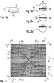
- Fig. 3 (a) further shown a single raised embossing element 34 and 3 (b) to (d) show different positions of a line segment 36 on the embossing element 34 in supervision.
- the security element 12 contains an optically variable structure 20, which is formed by a combination of an embossed structure 22 and a coating 24.
- the coating 24 comprises a highly reflective background layer 26, for example a full-surface reflective silver-colored printing layer with a high gloss value, which is screen-printed onto the banknote substrate 28 of the banknote 10.
- the banknote substrate 28 also represents the substrate of the security element 12, so that the security element 12 is integrated into the banknote 10.
- the silver background layer 26 gives the security element 12 its basically shiny metallic appearance.
- the lines 32 do not intersect one another and are at a distance that is largely not, however, completely constant along the longitudinal extent of the lines and are therefore also referred to as almost parallel in the context of this description.
- the desired movement effects arise precisely from the deviation of the line grids according to the invention from line grids with completely parallel lines.
- the line width b of the lines 32 is the same for all lines 32 in the exemplary embodiment and is constant along the longitudinal extent of the lines.
- the coating 24 formed by the background layer 26 and the line pattern 30 is combined with an embossing structure 22, which consists of a two-dimensional square pattern of embossing elements 34, which in the exemplary embodiment are formed by compressed hemispherical elevations, as in FIG Fig. 3 (a) shown in perspective view.
- the elevations 34 have, for example, a base area diameter d P of 250 ⁇ m and a height h p of 75 ⁇ m. As in Fig.
- the raster width W P of the embossing element grid is somewhat larger than the base area diameter dp and in the exemplary embodiment is 1.2 * d P , so that the raster width W P of the embossing element grid is also 300 ⁇ m and therefore corresponds to the average grid width W L of the line grid.
- each elevation 34 acts as a small arching mirror due to the silver background layer 26 and on the other hand essentially on each elevation 34 Line segment 36 of a line 32 from the line grid 30 lies.
- each elevation 34 should in principle carry a line segment 36, however, due to the specific course of the lines 32, there may also be some elevations 34 in the embossed structure on which no line segment 36 comes to lie, or a specific partial area the embossed structure purposefully not covered with line segments in order to create a static substructure within the dynamic movement effect of the optically variable structure.
- the parameter 'position of the line segment on the embossing element' is of particular importance in the context of the present invention.
- This line segment position can be specified in particular by a location-dependent phase function ⁇ (x, y), which depends on the position (x, y) of the embossing element 34 within the optically variable structure 20 and whose functional value is the relative position of the line segment 36 on the embossing element perpendicular to Longitude of the line segment 36, normalized to the unit interval [0, 1], indicates.
- ⁇ 0.25 ( Fig. 3 (b) )
- ⁇ 0.5 ( Fig. 3 (c) )
- ⁇ 0.75 ( Fig. 3 (d) ) shown.
- the present inventors have now surprisingly found that by varying the position of the line segments 36 on the embossing elements 34, a large number of different movement effects can be realized when the security element 12 is tilted. All of these different movement effects can be described by a corresponding location-dependent phase function ⁇ (x, y).
- the line segments 36 arranged on the elevations 34 produce a different color and brightness impression depending on the viewing direction 40, 42, 44, which also depends on the position of the respective elevation 34 within the optically variable structure when the line segments 36 are in a location-dependent position.
- the security element 12 therefore already shows a predetermined image motif, such as that in FIG Fig. 1 shown wing structure 14. If the security element 12 is tilted so that, for example, the viewing direction changes from the vertical direction 42 to an oblique direction 40, 44, the color and brightness of the optically variable structure change fluently but locally differently, so that the impression a movement arises.
- linear movements, rotational movements or complex forms of movement such as pump or "zoom" effects or counter-directional movements can be generated.
- Rotation effects have proven to be particularly impressive since the generation of a rotational movement by linearly tilting a security element runs counter to intuition and therefore has a surprising effect on the viewer.
- Such rotation effects can be generated in that the parameter 'position of the line segment on the embossing element' directly, in particular linearly, from the angle between the position (x, y) of the embossing element and a fixed reference point (x 0 , y 0 ) in the optically variable structure depends.
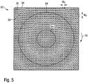
- Figure 4 shows a two-dimensional projection of a section of the associated line grid 30 of the security element 12 with the line segments 36 arranged according to the phase function ⁇ 1 (x, y) and the embossed elements 34 indicated in the outline. Because of the lack of spatial depth in the two-dimensional projection and the lack thereof The projection shows the dependence of the visual impression on the viewing direction Fig. 4 the rotation effect described does not occur, it only arises with a real three-dimensional, embossed security element 12.
- the line segments 36 lying in the middle of the elevations 34 are arranged essentially along the two diagonals 50, so that when viewed vertically, that in FIG Fig. 1 shown appearance with four, extending along the diagonal 50 wings 14 arises.
- the line segments 36 previously located at the highest point reach the lower flanks of the elevations 34 from the viewpoint of the beholder and therefore withdraw visually.
- the line segments 36 previously lying on the upper flanks are tilted to the highest point, so that they now dominate the visual appearance.
- the associated elevations 34 all lie essentially along the diagonals 52 rotated counterclockwise by an angle 18, so that after the tilting 16 there is an appearance with four wings 14 rotated counterclockwise by an angle 18.
- tilting the security element 12 upwards results in an apparent rotation of the wings 14 in a clockwise direction.
- small tilts 16 result in a rotation by a small angle 18
- larger tilts result in a rotation by a larger angle, so that the apparent rotational movement of the wings 14 runs smoothly when tilted.
- the full-surface, reflective silver-colored printing layer 26 is first printed on the banknote substrate 28 of the banknote 10. Then the line screen 30 is printed in offset printing on the silver layer 26, for example with an oxidative or UV-drying ink, e.g. B. Yellow. Subsequently, the embossed structure 22 with the elevations 34 on the upper side of the bank note 10 is produced by blind embossing in intaglio printing that does not lead to color. To stabilize the raised structure of the upper side, the rear side of the banknote substrate 28, which is deformed by the embossing, can be filled with lacquer. The embossed structure 22 is also advantageously provided with a transparent cover layer, not shown in the figure, which flattens the elevations 34 and thereby prevents the optically variable structure from being shaped.
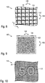
- Figure 5 shows a two-dimensional projection of a section of the associated line grid 60 of the security element 62 with the line segments 36 and the embossed elements 34 indicated in the outline.
- the line segments 36 lying in the middle of the elevations 34 are essentially arranged on concentric circles 64 with radii of 5 * W p , 15 * W p , 25 * W p , etc.
- the security element 62 therefore shows a series of concentric circles with the diameters mentioned.
- the line segments 36 initially lying at the highest point come from the viewpoint of the viewer to the lower flanks of the elevations 34 and therefore step back visually, while the line segments 36 previously lying on the upper flanks be tilted to the highest point and dominate the visual appearance.
- the corresponding elevations 34 lie on somewhat larger concentric circles, for example with radii 7 * W p , 17 * W p , etc., so that the concentric circles 64 appear to enlarge due to the tilting 16.
- a tilting of the security element 62 in the opposite direction results in an apparent reduction in the concentric circles 64, so that the desired pump effect is produced by tilting the security element 62 back and forth.
- phase function ⁇ 2 of the Fig. 5 is only mentioned as an example and that instead of circles, for example, squares, stars or other polygons, but also more complex objects such as symbols or value numbers, and also other distances between the concentric figures can be generated.
- the principle described is not limited to designs with a single line grid, rather the coating of a security element can also contain two or more line grids, the parameters' position of the line segment on the embossing element ',' orientation of the line segment on the embossing element for the line segments of each line grid 'and' shape of the line segment 'can vary independently.
- the line grids can therefore in particular also produce different movement effects or the same movement effects in different directions.
- the lines of the line grids are advantageously applied with different colors in order to visually differentiate the movement effects of the line grids.
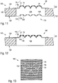
- FIG. 6 (a) the appearance of a security element with two line grids when viewed vertically and Fig. 6 (b) a detailed section of the security element 70.
- the embossed structure 22 already described above is combined with a coating which, in addition to the highly reflective background layer 26, contains two line grids 72, 74.
- the red line grid 72 then produces, as explained above, in interaction with the embossing structure 22 a red windmill structure with four blades 82 which, when the safety element 70 is tilted down (reference numeral 76), rotate counterclockwise (direction of rotation 86) seem to be.
- phase function ⁇ 3 (x, y) is rotated 45 ° to the right compared to the phase function ⁇ 1 (x, y) and its function values also decrease with increasing angle.
- the blue line grid therefore produces a blue windmill structure with four blades 84 which, in the starting position, are rotated 45 ° against the blades 82 of the red windmill structure when viewed vertically, and which rotate when the safety element is tilted 70 seem to turn downwards (reference numeral 76) clockwise (direction of rotation 88).
- Such a security element 70 with two opposite colored rotation effects is very conspicuous for the viewer and therefore has a high level of attention and recognition.
- FIG Fig. 7 Another embodiment of a security element 90 with differently colored line grids 92, 94 is shown in FIG Fig. 7 shown, for the sake of simplicity only the line grids are shown without the projected embossed elements.
- the line screens 92, 94 are printed with different colors, for example red and blue, using screen printing.
- the security element 90 provided with a highly reflective background layer 26 and the two line grids 92, 94 alternately shows vertical red and blue stripes which seem to move to the right or left when the security element is tilted in the tilt direction 96, that is to say an orthoparallactic movement behavior, where the direction of movement is perpendicular to the tilt direction.
- the apparent movement in the two partial areas is a mirror image of one another, so that, for example, when the security element 90 is tilted downward, the vertical red and blue stripes in the partial area 98-L follow Walk left and to the right in section 98-R.
- the plurality of line grids 102, 104 of a security element 100 can also be perpendicular to one another, for example in the case of a square embossing grid, as in FIG Fig. 8 illustrated.
- the lines of the line grid 102 extend essentially along the x-axis and therefore produce a movement effect when the security element 100 is tilted in the tilting direction 106, perpendicular to the x-axis.
- the lines of the line grid 104 extend essentially along the y axis and generate therefore a movement effect when tilting the security element 100 in the tilt direction 108, perpendicular to the y-axis.
- Figure 9 shows a specific exemplary embodiment of such a security element 100, only the two line grids 102, 104 without the projected embossing elements 34 being shown for the sake of simplicity.
- the line screens 102, 104 are printed with different colors and produce different movement effects when tilted in the tilt direction 106 and in the tilt direction 108, for example a pump effect in the tilt direction 106 and a rotation effect in the tilt direction 108.
- line grids can be provided in a hexagon grid, which essentially enclose angles of 60 ° or 120 ° between them.
- the movement effects described can also be combined with a static effect, that is to say with a partial area which does not take part in the apparent movement when tilting and thus represents a stationary pole in the moving environment.
- a security element 110 which is basically like the security element of Fig. 4 is trained.
- the line grid 30 in the security element 110 is, however, recessed in a partial area 112, which in the exemplary embodiment is in the form of the number sequence “50”, so that there are no line segments on the embossing elements 34.
- the security element 110 therefore shows an unchanged metallic appearance regardless of the tilting position of the security element, so that the security element 110 next to the rotating windmill structure 14 shows the stationary number sequence "50".
- a color in particular in a color tone different from the color tone of the line segments, can additionally be applied in the partial area 112, in which there are no line segments on the embossing elements 34, for example to enhance the static effect.
- a recess in the line grid 30 can be dispensed with and instead the line grid in the partial region 112 can be overprinted with a strongly opaque color.
- the embossing grid can alternatively be left out in the partial area 112, so that no embossing elements 34 are assigned to the line segments of the line grid in the partial area.
- the security element is tilted, the visual impression of the partial area does not change due to the lack of spatial depth and the resulting lack of dependence on the viewing direction and thus also represents a stationary pole in the moving environment.
- the optically variable effect is essentially only visible on one side of the security element.
- the invention also includes two-sided designs which each have an optically variable effect when viewed from opposite sides.
- optically variable structures are provided both on the front and on the back of a data carrier, which each have an embossed structure and a coating.
- the embossed structure of the back is produced in the same production step at the same time as the embossed structure of the front and is therefore congruent but inverse to the first embossed structure on the front.
- Fig. 11 a cross section of a polymer banknote 120, in the substrate 122 of which a transparent window area 128 is formed.
- a first optically variable structure 20 which is associated with FIGS Figures 2 to 10 already described in more detail arranged, which is formed by a combination of an embossed structure 22 and a coating 24.
- the coating 24 comprises two line grids 72, 74, as in the exemplary embodiment in FIG Fig. 6 described in more detail.
- the first optically variable structure 20 of the front side 124 is combined with a second optically variable structure 130 which is arranged on the back side 126 of the banknote and which has a second embossing structure 132 and a second coating 134, which is likewise formed by two line grids 136, 138 of the type described above is formed.
- the second embossing structure 132 was produced simultaneously with the first embossing structure 22 in the same production step, in the exemplary embodiment, for example, by means of a blind embossing step.
- the front of the banknote is the side of the substrate 122 facing the embossing plate in the embossing step Fig. 11
- the deformations of the rear generated due to production are also used as embossed structures 132.
- the embossed structures 132 have a geometry that is inverse to the embossed structures 22 of the front side, that This means that the elevations and depressions are congruent and with the same repeat, but with the roles of the elevations and depressions reversed. Due to the counter-pressure blanket used, the rear side embossing structures 132 have an increased roughness compared to the front side embossing structures 22.
- the positions of the line segments of the rear-side line grids 136, 138 are given by a phase function ⁇ RS (x, y), to which the statements made above regarding the phase functions of the front-side line grids also apply.
- the coating 134 and the embossed structure 132 are combined with one another by the corresponding values of their raster widths such that essentially a line segment of a line from the line rasters 136, 138 lies in each recess 135.
- the elevations 34 lying on the front side 124 of the substrate 122 act as small concave mirrors when viewed from the rear side 126.
- the curvature of the elevations 34 is matched to the thickness of the substrate 122 such that the focus of the small concave mirrors lies in the region of the lines of the line grid 136, 138.
- the line grids 72, 74 on the front and the line grids 136, 138 on the back can produce the same or different movement effects with their phase functions ⁇ VS (x, y) and ⁇ RS (x, y).
- the highly reflective background layer 26 can in particular be formed by a screen printing layer or a metallization.
- the background layer has a double function in this embodiment, since it is for both Groups of line patterns 72, 74 and 136, 138 each act as a reflective background.
- the substrate 122 When creating a design after Fig. 11 the substrate 122 is first provided with the highly reflective background layer 26 and the substrate prepared in this way is then printed on both sides with the line patterns 72, 74 or 136, 138.
- the printing can advantageously be carried out in a simultaneous process or in two separate printing steps.
- the substrate 122 is embossed blind, whereby the congruent embossed structures 22, 132 are simultaneously produced on the front and back and thus the first and second optically variable structures 20, 130 are completed.
- the embossing is advantageously carried out with the embossing plate on the side of the background layer 26, but in principle it can also be carried out on the opposite side.
- the illustrated two-sided design only uses an optically variable structure 140 on the front side 124 of the banknote in a transparent window area 128 of a banknote 120.
- the back 126 may have deformations, such as in FIG Fig. 2 shown, but in this embodiment they are not used as embossed structures of an optically variable rear structure.
- the optically variable structure 140 is formed by a combination of an embossed structure 22 and a coating 142, the coating 142 having two groups of line grids in addition to a highly reflective silver background layer 26.
- a first group of line grids 72, 74 is applied to the background layer 26 as in the exemplary embodiments described above, while a second group of line grids 144, 146 is arranged below the background layer 26.
- both groups of line grids use the same embossed structure 22, the elevations 34 acting as small curved mirrors for the line grids 72, 74 arranged on the background layer 26 and when viewed from the front, while they act for the line grids 144, arranged below the background layer 26 146 and when viewed from the rear act as a small concave mirror.
- the line grids 72, 74 on the background layer and the line grids 144, 146 below the background layer can produce the same or different movement effects with their phase functions ⁇ on (x, y) and ⁇ under (x, y).
- the contrasting or even reflecting background layer shows at least one movement effect when viewed from above on the security element.
- a movement effect is visible from above when viewed from opposite sides, wherein the movement effects of the opposite sides can be the same or different.
- these supervisory movement effects could be combined with transparency information in that the background layer is perforated with punctiform or line-shaped cutouts or is also omitted over a large area. If two background layers are provided, the cutouts are provided in at least one of the background layers. In the case of opaque background layers, it may be necessary to cut out both background layers so as to generate a view through information.
- Figure 13 shows for illustration a security element 150 with a highly reflective background layer 26 and two differently colored line grids 92, 94, the projected embossing elements not being shown for the sake of simplicity.
- a contour line 152 in the exemplary embodiment in the form of a butterfly motif, is introduced into the background layer 26 and the line grid 92, 94 lying above it.
- the security element 150 therefore has a clear view of the contour line 152 of the butterfly motif.
- the background layer 26 can also be removed over a large area by laser exposure, as in the modification of FIG Fig. 14 illustrated.
- the highly reflective background layer 26 and the line grid 92, 94 were first applied over the entire area of the security element 154 and then removed in the area 156 outside the butterfly motif 158 by laser exposure.
- a first optically variable structure, according to Fig. 11 is combined with a second optically variable structure on the opposite side of the substrate, the two-sided security element shows a colored butterfly 158 with colored wings and a movement effect of the type described above.
- the line grids on the front side can be colored yellow and blue and printed on the back with the colors red and green, so that the butterfly wings show different color gradients depending on the viewing angle and viewing side.
- only the background layer 26 and the line grid 92, 94 of the front side, but not the coating of the rear side, can be removed by the laser application.
- the background layer 26 can also be in a desired shape, for example in the form of the butterfly motif 158 Fig. 14 be applied. This procedure is particularly suitable when larger surface areas would have to be demetallized, but has the disadvantage that register fluctuations can occur between the background layer 26 printed or applied as a film element and the printed line grids 92, 94.
- the background layer 26 can also be applied or metallized with an area coverage of less than 100%, for example 50%, in the form of a fine line or dot pattern in order to obtain a partially transparent background layer and a partially transparent window area.
- FIG. 15 shows a banknote 160 with an opaque paper substrate 162 as an exemplary embodiment.
- a first optically variable structure 20 of the type described above, which is formed by a combination of an embossed structure 22 and a coating 24.
- the coating 24 comprises two line grids 72, 74, as in the exemplary embodiment in FIG Fig. 6 described in more detail.
- the first optically variable structure 20 of the front side 164 is combined with a second optically variable structure 180 arranged on the back side 166 of the banknote, which has a second embossed structure 182 and a second coating 170 which, in addition to a highly reflective silver background layer 176, has two line grids 172, 174 has.
- the second embossing structure 182 was, as in the embodiment of FIG Fig. 11 , produced in the same production step simultaneously with the first embossing structure 22, for example by a blind embossing step, so that the Fig. 11 made on the deformations of the back and the inverse geometry of the embossed structures 182 and 22 also for the embodiment of the Fig. 15 be valid.
- the background layers 26, 176 can be produced by screen printing twice on the front and back of the banknote substrate 162, or else by applying offset silver, an application of a silver patch or a silver-coated laminate strip. A combination of the methods mentioned is also an option.
- the silver background layers 26, 176 can have the same or different shape, geometry or fine structure.
- the substrate prepared in this way is printed on both sides with the line patterns 72, 74 or 172, 174.
- the printing can again advantageously be carried out in a simultaneous process or in two separate printing steps.
- the substrate 162 is embossed blind, whereby at the same time the congruent embossed structures 22, 182 are produced on the front and back and thus the two optically variable structures 20, 180 are completed.
- the line grids 72, 74 on the front and the line grids 172, 174 on the back with their phase functions ⁇ VS (x, y) and ⁇ RS (x, y) can produce the same or different movement effects.
- one or both of the background layers 26 ', 176' can also be in the form of a non-highly reflective layer.
- the background layer that contrasts with the line grids is in particular the white substrate surface of banknote paper, the colored surface of a colored substrate, a glossy adhesive layer applied to the substrate surface by screen printing with pigments (e.g. rutile - TiO 2 ) or fillers, or a substrate 162 applied monochrome printing layer in question.
- the background layer 26 ' is formed by a monochrome, for example red, printing layer
- the background layer 176' is formed by a monochrome, for example yellow printing layer.
- One or both of the background layers 26 ', 176' can also be formed by the white surface of the banknote substrate 162 itself.
- the formation of the background layer as not or only to a small extent reflective and only contrasting with the line grids naturally also applies to designs with only one background layer, such as in Fig. 2 or 12 shown into consideration.
- At least one luminescent color is advantageously used in the line screen.
- Luminescent inks are advantageously added to one to three, preferably two, of the printing inks used.
- the security element can then be verified with UV light, the viewer perceiving a colored movement in the security element, for example, when swiveling a UV hand lamp back and forth, without moving it himself.
- FIG 17 shows only a schematic representation of the embossed structure 192 of a security element 190, the embossed structure 192 containing as embossed elements both compressed hemispherical elevations 194 and compressed hemispherical depressions 196.
- the raised and recessed embossing elements 194, 196 are arranged in the form of a motif 198, in the exemplary embodiment the number sequence "50".
- the embossed structure 192 is combined with a coating of the type described above, a movement effect arises which is modified within the motif 198 because of the opposite optical effect of the raised and recessed embossed elements, so that the motif 198 appears clearly at least from certain viewing directions .
- the motif 198 cannot be seen, for example, when viewed vertically, while it shows a color sequence inverted from the environment when viewed from a flat angle.
- An embossing tool for producing such embossing structures can be produced, for example, by laser machining an embossing plate.
- Figure 18 shows a top view of a section of a security element 200, which is basically like the security element 12 of FIG Figures 2 and 3 is designed.
- the embossed structure 202 of the security element 200 also has a partial region 204 with elongated, raised embossed elements 206.
- the embossing elements 206 can be elliptical, oval or channel-shaped, for example.
- the elongated embossing elements 206 lie with their longitudinal direction parallel to the x-axis and their transverse direction parallel to the y-axis.
- the different, elongated shape of the embossing elements 206 does not lead to noticeable deviations in the appearance produced by the line grid 30 in the partial area 204 when tilting in the north-south direction (tilting about the x-axis) different shape of the embossing elements 206 is easily recognizable, for example, with the aid of a microscope and can therefore be used as a further authenticity feature.
- Such combinations of spherical and elongated embossed elements provide security element 200 with additional protection against forgery, in particular because, as explained in more detail above, corresponding combination lens foils are not commercially available.
- Figure 19 shows as a further embodiment a security element 210, which is basically like the security element 12 of FIG Figures 2 and 3 is configured, the embossing structure 212 of which, in addition to the regular two-dimensional grid 22 of stamping elements 214, also comprises a partial region 216 with stamping elements 218 offset from the grid 22.
- the offset embossing elements 218 have the same shape as the embossing elements 214, but in general the offset embossing elements can also have a different shape or a different dimension or raster width. Due to the phase shift, the subarea 216 has a different appearance from the surroundings and is therefore visible in the movement feature as additional information. If the embossing elements 218 are offset by just half the period length of the embossing element grid, the result is an inverted color appearance of the partial area 216 and thus an easily recognizable information in the security element 210.
- the optically variable security element 228 is designed such that, in addition to a partial area of the film element 222, it also includes the areas adjacent to the film element 222 224 of the banknote substrate 226 covered.
- a silvery, glossy background layer is provided on the film element 222, while the contrasting background layer in the regions 224 adjoining the film element is not a glossy background layer, but is formed, for example, by the white substrate surface or a colored printing layer.
- at least one line grid is provided, which extends both over the film element 222 and the adjacent areas 224.
- the banknote substrate 226 is blind embossed together with the applied foil element in order to produce a continuous embossed structure.
- the film element 222 is thereby securely bound to the banknote substrate 226, since manipulation of the film element is immediately noticeable due to the extension of the security element 228 into the adjacent areas 224.
- the security element 228 can also be arranged in the region of a through opening of the bank note 220 covered by the film element 222.
- the security element 228 is advantageously approximately with a two-sided design 11, 12 . 15 or 16 formed so that a movement effect is visible in the area of the opening even when looking at the rear.
- the coating of the security elements described can also have a number of subareas in which the line grids produce different movement effects.
- the security element 230 has a first partial area 232 in the form of the value number "50", the line grid of which produces a tilting effect.
- the surrounding partial area 23 has a line grid with a different movement effect, for example a rotation effect Figure 4 busy.
- the value number "50" is therefore dependent on the viewing angle visible or not visible, while the surroundings 236 of the value number shows rotating wings.
- the security elements described can also contain embossed structures with a one-dimensional raster.
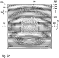
- Figure 22 illustrates this using the example of a security element 242, which is similar to the embodiment of FIG Fig. 5 shows a pumping effect. Specifically shows Fig. 22 in a two-dimensional projection, a section of the associated line grid 240 of the security element 242 with a plurality of elongated raised embossed elements 244, which are arranged essentially parallel to one another in a one-dimensional grid 246 of the grid width W P.
- the associated line grid 240 consists of a plurality of lines 250, which according to the at Fig. 5 specified phase function ⁇ 2 (x, y) are obtained.
- the coating with the line pattern 240 is combined with the embossed structure of the embossing elements 244 such that at least one line 250 of the line pattern 240 essentially lies on each elongated embossing element 244.
- the phase function ⁇ 2 (x, y) describes the local position and orientation of the line 250 on the embossing element 244 for each point (x, y).
- a line 250 can extend due to its specific course over several of the elongated embossing elements 244, so that only a partial area of this line 250 lies above each of these elongated embossing elements 244.
- the line parts lying in the center of the embossing elements 244 are essentially arranged on concentric circles 248 with radii of 5 * W p , 15 * W p , 25 * W p , etc.
- the security element 242 therefore shows a series of concentric circles with the diameters mentioned.
- the line parts which are initially at the highest point come to the lower flanks of the embossing elements 244 from the perspective of the viewer and step therefore back visually, while the line parts previously on the upper flanks are tilted to the highest point and dominate the visual appearance.
- the line parts that were previously visible now appear increasingly less dominant to the viewer, whereas the line parts previously located on the upper flanks are more clearly visible due to the tilting 16.
- the associated areas of the embossing elements 244 lie on somewhat larger concentric circles, for example with radii 7 * W p , 17 * W p , etc., so that the concentric circles 248 appear to enlarge due to the tilting 16.
- a tilting of the security element 242 in the opposite direction results in an apparent reduction in the concentric circles 248, so that the desired pumping effect occurs by tilting the security element 242 back and forth in the tilting direction 16.
- the lines 250 run essentially parallel to the longitudinal direction 252 of the elongated embossing elements 244 for an impressive movement effect.
- the lines 250 with the elongated embossing elements 244 reduce (or enlarge) one compared to the exemplary embodiment in FIG Fig. 22
- the described movement effect occurs only when tilting about the axis 252 parallel to the longitudinal axis of the embossing elements, while there is no movement effect when tilting about an axis perpendicular thereto.
- the exemplary embodiments shown are not exhaustive.
- combinations of the security element shown with other security features are provided.
- the security element can be combined on a security document with further optically variable elements that convey a different image impression to the viewer from different viewing angles and, depending on the viewing angle, show a different color or brightness impression and / or a different graphic motif.
- the security element shown picks up the direction of movement and / or the shapes of the further optically variable element (s).
- a hologram strip when tilting can be used to represent a movement of a motif in a certain direction, which is picked up by the security element according to the invention or is reproduced in a similar manner.
- a strengthening of the impression of movement can also be achieved by a further security feature, for example by moving the motif represented by the hologram in the opposite direction to the security element according to the invention.
Landscapes
- Physics & Mathematics (AREA)
- Optics & Photonics (AREA)
- Manufacturing & Machinery (AREA)
- Engineering & Computer Science (AREA)
- General Health & Medical Sciences (AREA)
- Toxicology (AREA)
- Electromagnetism (AREA)
- Health & Medical Sciences (AREA)
- Business, Economics & Management (AREA)
- Accounting & Taxation (AREA)
- Finance (AREA)
- General Physics & Mathematics (AREA)
- Credit Cards Or The Like (AREA)
- Printing Methods (AREA)
- Aiming, Guidance, Guns With A Light Source, Armor, Camouflage, And Targets (AREA)
Priority Applications (1)
| Application Number | Priority Date | Filing Date | Title |
|---|---|---|---|
| PL19000427T PL3616937T3 (pl) | 2014-12-12 | 2015-12-02 | Zmienny optycznie element zabezpieczający |
Applications Claiming Priority (3)
| Application Number | Priority Date | Filing Date | Title |
|---|---|---|---|
| DE102014018512.5A DE102014018512A1 (de) | 2014-12-12 | 2014-12-12 | Optisch variables Sicherheitselement |
| PCT/EP2015/002417 WO2016020066A2 (fr) | 2014-12-12 | 2015-12-02 | Élément de sécurité optiquement variable |
| EP15812954.4A EP3230080B1 (fr) | 2014-12-12 | 2015-12-02 | Élément de sécurité optiquement variable |
Related Parent Applications (2)
| Application Number | Title | Priority Date | Filing Date |
|---|---|---|---|
| EP15812954.4A Division EP3230080B1 (fr) | 2014-12-12 | 2015-12-02 | Élément de sécurité optiquement variable |
| EP15812954.4A Division-Into EP3230080B1 (fr) | 2014-12-12 | 2015-12-02 | Élément de sécurité optiquement variable |
Publications (2)
| Publication Number | Publication Date |
|---|---|
| EP3616937A1 true EP3616937A1 (fr) | 2020-03-04 |
| EP3616937B1 EP3616937B1 (fr) | 2021-08-18 |
Family
ID=54883978
Family Applications (2)
| Application Number | Title | Priority Date | Filing Date |
|---|---|---|---|
| EP15812954.4A Active EP3230080B1 (fr) | 2014-12-12 | 2015-12-02 | Élément de sécurité optiquement variable |
| EP19000427.5A Active EP3616937B1 (fr) | 2014-12-12 | 2015-12-02 | Élément de sécurité optiquement variable |
Family Applications Before (1)
| Application Number | Title | Priority Date | Filing Date |
|---|---|---|---|
| EP15812954.4A Active EP3230080B1 (fr) | 2014-12-12 | 2015-12-02 | Élément de sécurité optiquement variable |
Country Status (11)
| Country | Link |
|---|---|
| US (1) | US11511559B2 (fr) |
| EP (2) | EP3230080B1 (fr) |
| JP (1) | JP7292005B2 (fr) |
| CN (2) | CN107107649B (fr) |
| BR (1) | BR112017012334B1 (fr) |
| CA (1) | CA2970398C (fr) |
| DE (4) | DE102014018512A1 (fr) |
| HU (2) | HUE047567T2 (fr) |
| PL (2) | PL3230080T3 (fr) |
| RU (1) | RU2697485C2 (fr) |
| WO (1) | WO2016020066A2 (fr) |
Families Citing this family (22)
| Publication number | Priority date | Publication date | Assignee | Title |
|---|---|---|---|---|
| US20140272237A1 (en) * | 2013-03-15 | 2014-09-18 | Prc-Desoto International, Inc. | Strippable film assembly and coating for drag reduction |
| DE102015015991A1 (de) * | 2015-12-10 | 2017-06-14 | Giesecke & Devrient Gmbh | Sicherheitselement mit Linsenrasterbild |
| DE102016007784A1 (de) | 2016-06-24 | 2017-12-28 | Giesecke+Devrient Currency Technology Gmbh | Optisch variables Sicherheitselement |
| RU2651339C1 (ru) * | 2017-04-12 | 2018-04-19 | Акционерное общество "ГОЗНАК" | Защищенный носитель информации, обладающий оптически переменным эффектом, и способ изготовления защищенного носителя информации |
| DE102017004682A1 (de) | 2017-05-16 | 2018-11-22 | Giesecke+Devrient Currency Technology Gmbh | Verfahren zur Absicherung eines Teilprodukts und System mit einem abgesicherten Teilprodukt |
| DE102017006513A1 (de) | 2017-07-10 | 2019-01-10 | Giesecke+Devrient Currency Technology Gmbh | Sicherheitselement mit optisch variabler 2-dimensionaler Prägestruktur |
| DE102017006949A1 (de) | 2017-07-21 | 2019-01-24 | Giesecke+Devrient Currency Technology Gmbh | Sicherheitselement mit optisch variabler Prägestruktur |
| DE102017009092A1 (de) | 2017-09-28 | 2019-03-28 | Giesecke+Devrient Currency Technology Gmbh | Verfahren zur Herstellung eines optisch variablen Elements sowie entsprechendes Element |
| DE102017009226A1 (de) * | 2017-10-04 | 2019-04-04 | Giesecke+Devrient Currency Technology Gmbh | Optisch variables Durchsichtssicherheitselement und Datenträger |
| DE102017011455A1 (de) | 2017-12-12 | 2019-06-13 | Giesecke+Devrient Currency Technology Gmbh | An unterschiedliche Kundenwünsche anpassbares Sicherheitselement mit einer optisch variablen Struktur |
| US20200384797A1 (en) | 2017-12-27 | 2020-12-10 | Takeshi Kuroda | Three-dimensional decorative piece made of thermoplastic synthetic resin and method for producing the same |
| US10821765B2 (en) | 2018-01-10 | 2020-11-03 | Assa Abloy Ab | Secure documents and methods of manufacturing the same |
| US10350935B1 (en) * | 2018-01-10 | 2019-07-16 | Assa Abloy Ab | Secure document having image established with metal complex ink |
| DE102018005447A1 (de) * | 2018-07-09 | 2020-01-09 | Giesecke+Devrient Currency Technology Gmbh | Optisch variables Sicherheitselement mit reflektivem Flächenbereich |
| DE102018005697A1 (de) * | 2018-07-19 | 2020-01-23 | Giesecke+Devrient Currency Technology Gmbh | Sicherheitselement mit Linsenrasterbild |
| JP6991511B2 (ja) * | 2018-08-03 | 2022-02-03 | 独立行政法人 国立印刷局 | 潜像印刷物 |
| WO2020055892A1 (fr) * | 2018-09-10 | 2020-03-19 | Crane & Co., Inc. | Document de sécurité entièrement micro-optique |
| DE102018010078A1 (de) * | 2018-12-20 | 2020-06-25 | Giesecke+Devrient Currency Technology Gmbh | Optisch variables Sicherheitselement |
| DE102019000739A1 (de) * | 2019-02-01 | 2020-08-06 | Giesecke+Devrient Mobile Security Gmbh | Identifikationsdokument mit biometrischer Bildinformation |
| CN112572019B (zh) * | 2019-09-30 | 2022-03-01 | 中钞特种防伪科技有限公司 | 光学防伪元件及防伪产品 |
| DE102024103599A1 (de) | 2024-02-08 | 2025-08-14 | Giesecke+Devrient Currency Technology Gmbh | Sicherheitselement und Verfahren zur Herstellung eines Sicherheitselements |
| WO2025247588A1 (fr) * | 2024-05-31 | 2025-12-04 | Rolic Technologies AG | Dispositif de sécurité optique |
Citations (4)
| Publication number | Priority date | Publication date | Assignee | Title |
|---|---|---|---|---|
| EP0581414A1 (fr) * | 1992-06-04 | 1994-02-02 | Director-General, Printing Bureau, Ministry Of Finance, Japan | Objet de formation d'images latentes anti-contre façon pour des billets de banques cartes de crédit etc. et procédé de production |
| WO2009139396A1 (fr) * | 2008-05-01 | 2009-11-19 | 独立行政法人 国立印刷局 | Matériau de formation d’image, dispositif de détermination d’authenticité et procédé de détermination d’authenticité |
| EP2562726A1 (fr) * | 2010-08-03 | 2013-02-27 | Federalnoe Gosudarstvennoe Unitarnoe Predpriyatie "Goznak" (FGUP "Goznak") | Support d'informations à structure optique variable (et variantes) |
| DE102013000152A1 (de) | 2013-01-04 | 2014-07-10 | Giesecke & Devrient Gmbh | Verfahren zum Herstellen eines Sicherheitselements mit einer lasersensitiven Aufzeichnungsschicht |
Family Cites Families (46)
| Publication number | Priority date | Publication date | Assignee | Title |
|---|---|---|---|---|
| ES8609233A1 (es) | 1984-10-09 | 1986-09-01 | Syntex Inc | Procedimiento para preparar compuestos intermedios para ob- tener derivados de los acidos 16-fenoxi y 16-fenoxi susti- tuido-prostatrienoicos |
| US5428479A (en) * | 1989-09-04 | 1995-06-27 | Commonwealth Scientific And Industrial Research Organisation | Diffraction grating and method of manufacture |
| EP1182054B1 (fr) | 1995-11-28 | 2009-05-13 | OVD Kinegram AG | Porteur d'informations optiques |
| US6819775B2 (en) * | 1996-07-05 | 2004-11-16 | ECOLE POLYTECHNIQUE FéDéRALE DE LAUSANNE | Authentication of documents and valuable articles by using moire intensity profiles |
| BR0007172A (pt) * | 1999-09-30 | 2001-09-04 | Koninkl Philips Electronics Nv | Dispositivo lenticular, e, conjunto de dispositivos lenticulares |
| DE10044464B4 (de) | 2000-09-08 | 2011-09-22 | Giesecke & Devrient Gmbh | Datenträger sowie ein Verfahren zu seiner Herstellung |
| EP1534535B1 (fr) * | 2002-08-13 | 2010-06-09 | Giesecke & Devrient GmbH | Support de donnees element optiquement variable |
| DE10243863A1 (de) | 2002-08-13 | 2004-02-26 | Giesecke & Devrient Gmbh | Datenträger mit einem optisch variablen Element |
| US7305105B2 (en) * | 2005-06-10 | 2007-12-04 | Ecole polytechnique fédérale de Lausanne (EPFL) | Authentication of secure items by shape level lines |
| KR101225311B1 (ko) * | 2003-11-21 | 2013-01-22 | 비쥬얼 피직스 엘엘씨 | 마이크로-광학 보안 및 화상 연출 시스템 |
| DE102005011612A1 (de) | 2004-08-13 | 2006-02-23 | Giesecke & Devrient Gmbh | Datenträger mit einer optisch variablen Struktur |
| ES2563755T3 (es) * | 2005-05-18 | 2016-03-16 | Visual Physics, Llc | Presentación de imágenes y sistema de seguridad micro-óptico |
| DE102005061749A1 (de) * | 2005-12-21 | 2007-07-05 | Giesecke & Devrient Gmbh | Optisch variables Sicherheitselement und Verfahren zu seiner Herstellung |
| DE102005062132A1 (de) | 2005-12-23 | 2007-07-05 | Giesecke & Devrient Gmbh | Sicherheitselement |
| JP4844894B2 (ja) | 2006-01-26 | 2011-12-28 | 独立行政法人 国立印刷局 | 立体モアレ形成体 |
| DE102006006501A1 (de) | 2006-02-13 | 2007-08-16 | Giesecke & Devrient Gmbh | Sicherheitselement mit einer optisch variablen Struktur |
| DE102006029536B4 (de) | 2006-06-26 | 2011-05-05 | Ovd Kinegram Ag | Mehrschichtkörper mit Mikrolinsen sowie Verfahren zu seiner Herstellung |
| CN1888949A (zh) * | 2006-07-12 | 2007-01-03 | 张华升 | 隐藏图像识别系统、制品、识别装置及制作方法 |
| DE102006032660A1 (de) | 2006-07-13 | 2008-01-17 | Ovd Kinegram Ag | Mehrschichtkörper mit Mikrooptik |
| DE102006057507A1 (de) | 2006-12-06 | 2008-06-12 | Merck Patent Gmbh | Optisch variables Sicherheitselement |
| DE102007029203A1 (de) | 2007-06-25 | 2009-01-08 | Giesecke & Devrient Gmbh | Sicherheitselement |
| DE102007059550A1 (de) | 2007-12-11 | 2009-06-25 | Giesecke & Devrient Gmbh | Optisch variables Sicherheitselement |
| DE102007062089A1 (de) * | 2007-12-21 | 2009-07-02 | Giesecke & Devrient Gmbh | Verfahren zum Erzeugen einer Mikrostruktur |
| DE102008036482A1 (de) | 2008-08-05 | 2010-02-11 | Giesecke & Devrient Gmbh | Verfahren zum Herstellen von Mikrolinsen |
| EP2338150B1 (fr) | 2008-08-05 | 2021-03-17 | Giesecke+Devrient Currency Technology GmbH | Dispositif de sécurité |
| DE102009004128A1 (de) | 2009-01-05 | 2010-07-08 | Giesecke & Devrient Gmbh | Sicherheitselement mit optisch variabler Struktur |
| DE102009022612A1 (de) * | 2009-05-26 | 2010-12-02 | Giesecke & Devrient Gmbh | Sicherheitselement, Sicherheitssystem und Herstellungsverfahren dafür |
| DE102009032697C5 (de) | 2009-07-09 | 2020-03-05 | Ovd Kinegram Ag | Mehrschichtkörper |
| GB0919112D0 (en) | 2009-10-30 | 2009-12-16 | Rue De Int Ltd | Security device |
| GB201003398D0 (en) * | 2010-03-01 | 2010-04-14 | Rue De Int Ltd | Optical device |
| DE102010019766A1 (de) * | 2010-05-07 | 2011-11-10 | Giesecke & Devrient Gmbh | Verfahren zur Erzeugung einer Mikrostruktur auf einem Träger |
| DE102010025775A1 (de) * | 2010-07-01 | 2012-01-05 | Giesecke & Devrient Gmbh | Sicherheitselement sowie Wertdokument mit einem solchen Sicherheitselement |
| GB2495686B (en) | 2010-08-23 | 2016-12-28 | Innovia Security Pty Ltd | Multichannel opticallly variable device |
| RU2465147C1 (ru) | 2011-03-10 | 2012-10-27 | Федеральное Государственное Унитарное Предприятие "Гознак" (Фгуп "Гознак") | Полимерный многослойный защитный элемент, обладающий оптически переменным эффектом |
| GB201107657D0 (en) * | 2011-05-09 | 2011-06-22 | Rue De Int Ltd | Security device |
| DE102011116408A1 (de) | 2011-10-19 | 2013-04-25 | Giesecke & Devrient Gmbh | Verfahren zum Herstellen von Mikrohohlspiegeln |
| DE102011117677A1 (de) | 2011-11-04 | 2013-05-08 | Giesecke & Devrient Gmbh | Optisch variables Sicherheitselement |
| EP2594149A1 (fr) | 2011-11-18 | 2013-05-22 | Fabrica Nacional De Moneda Y Timbre - Real Casa De La Moneda | Objet comportant une région de sa surface adaptée pour montrer plusieurs images |
| GB201212046D0 (en) * | 2012-07-06 | 2012-08-22 | Rue De Int Ltd | Security devices |
| JP5967651B2 (ja) | 2012-10-22 | 2016-08-10 | 独立行政法人 国立印刷局 | 色変化印刷物 |
| PL2941356T3 (pl) * | 2012-12-10 | 2017-09-29 | Orell Füssli Sicherheitsdruck Ag | Dokument bezpieczeństwa z cechą bezpieczeństwa |
| HK1218279A1 (zh) * | 2013-02-08 | 2017-02-10 | Graphic Security Systems Corporation | 多阴影潜像 |
| DE102013105246B4 (de) * | 2013-05-22 | 2017-03-23 | Leonhard Kurz Stiftung & Co. Kg | Optisch variables Element |
| US9873281B2 (en) * | 2013-06-13 | 2018-01-23 | Visual Physics, Llc | Single layer image projection film |
| DE102013021806A1 (de) | 2013-12-20 | 2015-06-25 | Giesecke & Devrient Gmbh | Sicherheitselemente zur Darstellung zumindest einer optisch variablen Information |
| GB2550168B (en) * | 2016-05-11 | 2018-07-25 | De La Rue Int Ltd | Security device and method of manufacture |
-
2014
- 2014-12-12 DE DE102014018512.5A patent/DE102014018512A1/de active Pending
-
2015
- 2015-12-02 DE DE202015009513.5U patent/DE202015009513U1/de not_active Expired - Lifetime
- 2015-12-02 DE DE202015009514.3U patent/DE202015009514U1/de not_active Expired - Lifetime
- 2015-12-02 WO PCT/EP2015/002417 patent/WO2016020066A2/fr not_active Ceased
- 2015-12-02 EP EP15812954.4A patent/EP3230080B1/fr active Active
- 2015-12-02 CN CN201580073475.6A patent/CN107107649B/zh active Active
- 2015-12-02 CN CN201911104981.3A patent/CN110774796B/zh active Active
- 2015-12-02 RU RU2017124615A patent/RU2697485C2/ru active
- 2015-12-02 PL PL15812954T patent/PL3230080T3/pl unknown
- 2015-12-02 EP EP19000427.5A patent/EP3616937B1/fr active Active
- 2015-12-02 HU HUE15812954A patent/HUE047567T2/hu unknown
- 2015-12-02 DE DE202015009515.1U patent/DE202015009515U1/de not_active Expired - Lifetime
- 2015-12-02 BR BR112017012334-7A patent/BR112017012334B1/pt active IP Right Grant
- 2015-12-02 PL PL19000427T patent/PL3616937T3/pl unknown
- 2015-12-02 JP JP2017530114A patent/JP7292005B2/ja active Active
- 2015-12-02 US US15/535,368 patent/US11511559B2/en active Active
- 2015-12-02 CA CA2970398A patent/CA2970398C/fr active Active
- 2015-12-02 HU HUE19000427A patent/HUE057008T2/hu unknown
Patent Citations (4)
| Publication number | Priority date | Publication date | Assignee | Title |
|---|---|---|---|---|
| EP0581414A1 (fr) * | 1992-06-04 | 1994-02-02 | Director-General, Printing Bureau, Ministry Of Finance, Japan | Objet de formation d'images latentes anti-contre façon pour des billets de banques cartes de crédit etc. et procédé de production |
| WO2009139396A1 (fr) * | 2008-05-01 | 2009-11-19 | 独立行政法人 国立印刷局 | Matériau de formation d’image, dispositif de détermination d’authenticité et procédé de détermination d’authenticité |
| EP2562726A1 (fr) * | 2010-08-03 | 2013-02-27 | Federalnoe Gosudarstvennoe Unitarnoe Predpriyatie "Goznak" (FGUP "Goznak") | Support d'informations à structure optique variable (et variantes) |
| DE102013000152A1 (de) | 2013-01-04 | 2014-07-10 | Giesecke & Devrient Gmbh | Verfahren zum Herstellen eines Sicherheitselements mit einer lasersensitiven Aufzeichnungsschicht |
Also Published As
| Publication number | Publication date |
|---|---|
| CN107107649A (zh) | 2017-08-29 |
| EP3230080A2 (fr) | 2017-10-18 |
| EP3230080B1 (fr) | 2019-11-06 |
| JP7292005B2 (ja) | 2023-06-16 |
| BR112017012334B1 (pt) | 2022-04-19 |
| HUE047567T2 (hu) | 2020-04-28 |
| RU2697485C2 (ru) | 2019-08-14 |
| CN110774796A (zh) | 2020-02-11 |
| US20170326900A1 (en) | 2017-11-16 |
| RU2017124615A3 (fr) | 2019-06-17 |
| PL3230080T3 (pl) | 2020-05-18 |
| BR112017012334A2 (pt) | 2018-02-27 |
| WO2016020066A3 (fr) | 2016-04-21 |
| CN107107649B (zh) | 2019-12-06 |
| DE202015009513U1 (de) | 2018-02-01 |
| DE202015009515U1 (de) | 2018-02-08 |
| DE102014018512A1 (de) | 2016-06-16 |
| CA2970398A1 (fr) | 2016-02-11 |
| EP3616937B1 (fr) | 2021-08-18 |
| WO2016020066A2 (fr) | 2016-02-11 |
| RU2017124615A (ru) | 2019-01-14 |
| CN110774796B (zh) | 2021-03-30 |
| JP2017538604A (ja) | 2017-12-28 |
| CA2970398C (fr) | 2023-06-20 |
| HUE057008T2 (hu) | 2022-04-28 |
| DE202015009514U1 (de) | 2018-02-01 |
| PL3616937T3 (pl) | 2021-12-06 |
| US11511559B2 (en) | 2022-11-29 |
Similar Documents
| Publication | Publication Date | Title |
|---|---|---|
| EP3616937B1 (fr) | Élément de sécurité optiquement variable | |
| EP3820713B1 (fr) | Élément de sécurité optiquement variable à zone de surface réfléchissante | |
| EP3980273B1 (fr) | Élément de sécurité optiquement variable à zone de surface réfléchissante multicolore | |
| EP2909660B1 (fr) | Motif surfacique optiquement variable | |
| EP1966769B2 (fr) | Elément de sécurité à variation d'aspect et son procédé de fabrication | |
| EP4234261B1 (fr) | Élément optiquement variable | |
| EP3475096B1 (fr) | Élément de sécurité optique variable | |
| EP3233512B1 (fr) | Élément de sécurité transparent variable optiquement | |
| EP2889152B1 (fr) | Élément de sécurité destiné à représenter au moins une information variable optiquement | |
| WO2020011391A1 (fr) | Élément de sécurité optiquement variable à zone de surface réfléchissante | |
| DE102016015393A1 (de) | Sicherheitselement mit reflektivem Flächenbereich | |
| DE102005028162A1 (de) | Sicherheitselement und Verfahren zu seiner Herstellung | |
| EP2795377A1 (fr) | Motif bidimensionnel optiquement variable | |
| EP2897812A1 (fr) | Élément de sécurité à système de visualisation | |
| EP3648983B1 (fr) | Système de sécurité optiquement variable | |
| EP2768660A1 (fr) | Procédé de réalisation de micro-miroirs creux | |
| EP2886363B1 (fr) | Élément de sécurité pour papiers de sécurité | |
| EP3655254B1 (fr) | Élément de sécurité à structure en relief optiquement variable | |
| DE102012025262A1 (de) | Verfahren zur Herstellung eines Sicherheitselementes | |
| DE102012025264B4 (de) | Verfahren zur Herstellung eines Sicherheitselementes | |
| DE102005063700B4 (de) | Optisch variables Sicherheitselement und Verfahren zu seiner Herstellung | |
| DE102019003518A1 (de) | Sicherheitselement mit optisch variablem Flächenmuster |
Legal Events
| Date | Code | Title | Description |
|---|---|---|---|
| PUAI | Public reference made under article 153(3) epc to a published international application that has entered the european phase |
Free format text: ORIGINAL CODE: 0009012 |
|
| STAA | Information on the status of an ep patent application or granted ep patent |
Free format text: STATUS: THE APPLICATION HAS BEEN PUBLISHED |
|
| AC | Divisional application: reference to earlier application |
Ref document number: 3230080 Country of ref document: EP Kind code of ref document: P |
|
| AK | Designated contracting states |
Kind code of ref document: A1 Designated state(s): AL AT BE BG CH CY CZ DE DK EE ES FI FR GB GR HR HU IE IS IT LI LT LU LV MC MK MT NL NO PL PT RO RS SE SI SK SM TR |
|
| STAA | Information on the status of an ep patent application or granted ep patent |
Free format text: STATUS: REQUEST FOR EXAMINATION WAS MADE |
|
| 17P | Request for examination filed |
Effective date: 20200904 |
|
| RBV | Designated contracting states (corrected) |
Designated state(s): AL AT BE BG CH CY CZ DE DK EE ES FI FR GB GR HR HU IE IS IT LI LT LU LV MC MK MT NL NO PL PT RO RS SE SI SK SM TR |
|
| GRAP | Despatch of communication of intention to grant a patent |
Free format text: ORIGINAL CODE: EPIDOSNIGR1 |
|
| STAA | Information on the status of an ep patent application or granted ep patent |
Free format text: STATUS: GRANT OF PATENT IS INTENDED |
|
| GRAJ | Information related to disapproval of communication of intention to grant by the applicant or resumption of examination proceedings by the epo deleted |
Free format text: ORIGINAL CODE: EPIDOSDIGR1 |
|
| STAA | Information on the status of an ep patent application or granted ep patent |
Free format text: STATUS: REQUEST FOR EXAMINATION WAS MADE |
|
| INTG | Intention to grant announced |
Effective date: 20210209 |
|
| GRAP | Despatch of communication of intention to grant a patent |
Free format text: ORIGINAL CODE: EPIDOSNIGR1 |
|
| STAA | Information on the status of an ep patent application or granted ep patent |
Free format text: STATUS: GRANT OF PATENT IS INTENDED |
|
| INTC | Intention to grant announced (deleted) | ||
| INTG | Intention to grant announced |
Effective date: 20210329 |
|
| GRAS | Grant fee paid |
Free format text: ORIGINAL CODE: EPIDOSNIGR3 |
|
| GRAA | (expected) grant |
Free format text: ORIGINAL CODE: 0009210 |
|
| STAA | Information on the status of an ep patent application or granted ep patent |
Free format text: STATUS: THE PATENT HAS BEEN GRANTED |
|
| AC | Divisional application: reference to earlier application |
Ref document number: 3230080 Country of ref document: EP Kind code of ref document: P |
|
| AK | Designated contracting states |
Kind code of ref document: B1 Designated state(s): AL AT BE BG CH CY CZ DE DK EE ES FI FR GB GR HR HU IE IS IT LI LT LU LV MC MK MT NL NO PL PT RO RS SE SI SK SM TR |
|
| REG | Reference to a national code |
Ref country code: GB Ref legal event code: FG4D Free format text: NOT ENGLISH |
|
| REG | Reference to a national code |
Ref country code: CH Ref legal event code: EP |
|
| REG | Reference to a national code |
Ref country code: DE Ref legal event code: R096 Ref document number: 502015015093 Country of ref document: DE |
|
| REG | Reference to a national code |
Ref country code: IE Ref legal event code: FG4D Free format text: LANGUAGE OF EP DOCUMENT: GERMAN Ref country code: AT Ref legal event code: REF Ref document number: 1421303 Country of ref document: AT Kind code of ref document: T Effective date: 20210915 |
|
| REG | Reference to a national code |
Ref country code: LT Ref legal event code: MG9D |
|
| REG | Reference to a national code |
Ref country code: NL Ref legal event code: MP Effective date: 20210818 |
|
| PG25 | Lapsed in a contracting state [announced via postgrant information from national office to epo] |
Ref country code: FI Free format text: LAPSE BECAUSE OF FAILURE TO SUBMIT A TRANSLATION OF THE DESCRIPTION OR TO PAY THE FEE WITHIN THE PRESCRIBED TIME-LIMIT Effective date: 20210818 Ref country code: ES Free format text: LAPSE BECAUSE OF FAILURE TO SUBMIT A TRANSLATION OF THE DESCRIPTION OR TO PAY THE FEE WITHIN THE PRESCRIBED TIME-LIMIT Effective date: 20210818 Ref country code: SE Free format text: LAPSE BECAUSE OF FAILURE TO SUBMIT A TRANSLATION OF THE DESCRIPTION OR TO PAY THE FEE WITHIN THE PRESCRIBED TIME-LIMIT Effective date: 20210818 Ref country code: RS Free format text: LAPSE BECAUSE OF FAILURE TO SUBMIT A TRANSLATION OF THE DESCRIPTION OR TO PAY THE FEE WITHIN THE PRESCRIBED TIME-LIMIT Effective date: 20210818 Ref country code: LT Free format text: LAPSE BECAUSE OF FAILURE TO SUBMIT A TRANSLATION OF THE DESCRIPTION OR TO PAY THE FEE WITHIN THE PRESCRIBED TIME-LIMIT Effective date: 20210818 Ref country code: HR Free format text: LAPSE BECAUSE OF FAILURE TO SUBMIT A TRANSLATION OF THE DESCRIPTION OR TO PAY THE FEE WITHIN THE PRESCRIBED TIME-LIMIT Effective date: 20210818 Ref country code: NO Free format text: LAPSE BECAUSE OF FAILURE TO SUBMIT A TRANSLATION OF THE DESCRIPTION OR TO PAY THE FEE WITHIN THE PRESCRIBED TIME-LIMIT Effective date: 20211118 Ref country code: PT Free format text: LAPSE BECAUSE OF FAILURE TO SUBMIT A TRANSLATION OF THE DESCRIPTION OR TO PAY THE FEE WITHIN THE PRESCRIBED TIME-LIMIT Effective date: 20211220 |
|
| PG25 | Lapsed in a contracting state [announced via postgrant information from national office to epo] |
Ref country code: LV Free format text: LAPSE BECAUSE OF FAILURE TO SUBMIT A TRANSLATION OF THE DESCRIPTION OR TO PAY THE FEE WITHIN THE PRESCRIBED TIME-LIMIT Effective date: 20210818 Ref country code: GR Free format text: LAPSE BECAUSE OF FAILURE TO SUBMIT A TRANSLATION OF THE DESCRIPTION OR TO PAY THE FEE WITHIN THE PRESCRIBED TIME-LIMIT Effective date: 20211119 |
|
| PG25 | Lapsed in a contracting state [announced via postgrant information from national office to epo] |
Ref country code: NL Free format text: LAPSE BECAUSE OF FAILURE TO SUBMIT A TRANSLATION OF THE DESCRIPTION OR TO PAY THE FEE WITHIN THE PRESCRIBED TIME-LIMIT Effective date: 20210818 |
|
| REG | Reference to a national code |
Ref country code: HU Ref legal event code: AG4A Ref document number: E057008 Country of ref document: HU |
|
| PG25 | Lapsed in a contracting state [announced via postgrant information from national office to epo] |
Ref country code: DK Free format text: LAPSE BECAUSE OF FAILURE TO SUBMIT A TRANSLATION OF THE DESCRIPTION OR TO PAY THE FEE WITHIN THE PRESCRIBED TIME-LIMIT Effective date: 20210818 |
|
| REG | Reference to a national code |
Ref country code: DE Ref legal event code: R097 Ref document number: 502015015093 Country of ref document: DE |
|
| PG25 | Lapsed in a contracting state [announced via postgrant information from national office to epo] |
Ref country code: SM Free format text: LAPSE BECAUSE OF FAILURE TO SUBMIT A TRANSLATION OF THE DESCRIPTION OR TO PAY THE FEE WITHIN THE PRESCRIBED TIME-LIMIT Effective date: 20210818 Ref country code: SK Free format text: LAPSE BECAUSE OF FAILURE TO SUBMIT A TRANSLATION OF THE DESCRIPTION OR TO PAY THE FEE WITHIN THE PRESCRIBED TIME-LIMIT Effective date: 20210818 Ref country code: RO Free format text: LAPSE BECAUSE OF FAILURE TO SUBMIT A TRANSLATION OF THE DESCRIPTION OR TO PAY THE FEE WITHIN THE PRESCRIBED TIME-LIMIT Effective date: 20210818 Ref country code: EE Free format text: LAPSE BECAUSE OF FAILURE TO SUBMIT A TRANSLATION OF THE DESCRIPTION OR TO PAY THE FEE WITHIN THE PRESCRIBED TIME-LIMIT Effective date: 20210818 Ref country code: CZ Free format text: LAPSE BECAUSE OF FAILURE TO SUBMIT A TRANSLATION OF THE DESCRIPTION OR TO PAY THE FEE WITHIN THE PRESCRIBED TIME-LIMIT Effective date: 20210818 Ref country code: AL Free format text: LAPSE BECAUSE OF FAILURE TO SUBMIT A TRANSLATION OF THE DESCRIPTION OR TO PAY THE FEE WITHIN THE PRESCRIBED TIME-LIMIT Effective date: 20210818 |
|
| PLBE | No opposition filed within time limit |
Free format text: ORIGINAL CODE: 0009261 |
|
| STAA | Information on the status of an ep patent application or granted ep patent |
Free format text: STATUS: NO OPPOSITION FILED WITHIN TIME LIMIT |
|
| 26N | No opposition filed |
Effective date: 20220519 |
|
| PG25 | Lapsed in a contracting state [announced via postgrant information from national office to epo] |
Ref country code: MC Free format text: LAPSE BECAUSE OF FAILURE TO SUBMIT A TRANSLATION OF THE DESCRIPTION OR TO PAY THE FEE WITHIN THE PRESCRIBED TIME-LIMIT Effective date: 20210818 |
|
| PG25 | Lapsed in a contracting state [announced via postgrant information from national office to epo] |
Ref country code: SI Free format text: LAPSE BECAUSE OF FAILURE TO SUBMIT A TRANSLATION OF THE DESCRIPTION OR TO PAY THE FEE WITHIN THE PRESCRIBED TIME-LIMIT Effective date: 20210818 |
|
| REG | Reference to a national code |
Ref country code: BE Ref legal event code: MM Effective date: 20211231 |
|
| PG25 | Lapsed in a contracting state [announced via postgrant information from national office to epo] |
Ref country code: LU Free format text: LAPSE BECAUSE OF NON-PAYMENT OF DUE FEES Effective date: 20211202 Ref country code: IE Free format text: LAPSE BECAUSE OF NON-PAYMENT OF DUE FEES Effective date: 20211202 |
|
| PG25 | Lapsed in a contracting state [announced via postgrant information from national office to epo] |
Ref country code: BE Free format text: LAPSE BECAUSE OF NON-PAYMENT OF DUE FEES Effective date: 20211231 |
|
| P01 | Opt-out of the competence of the unified patent court (upc) registered |
Effective date: 20230520 |
|
| PG25 | Lapsed in a contracting state [announced via postgrant information from national office to epo] |
Ref country code: CY Free format text: LAPSE BECAUSE OF FAILURE TO SUBMIT A TRANSLATION OF THE DESCRIPTION OR TO PAY THE FEE WITHIN THE PRESCRIBED TIME-LIMIT Effective date: 20210818 |
|
| PG25 | Lapsed in a contracting state [announced via postgrant information from national office to epo] |
Ref country code: MK Free format text: LAPSE BECAUSE OF FAILURE TO SUBMIT A TRANSLATION OF THE DESCRIPTION OR TO PAY THE FEE WITHIN THE PRESCRIBED TIME-LIMIT Effective date: 20210818 |
|
| REG | Reference to a national code |
Ref country code: CH Ref legal event code: U11 Free format text: ST27 STATUS EVENT CODE: U-0-0-U10-U11 (AS PROVIDED BY THE NATIONAL OFFICE) Effective date: 20260101 |
|
| PGFP | Annual fee paid to national office [announced via postgrant information from national office to epo] |
Ref country code: GB Payment date: 20251218 Year of fee payment: 11 |
|
| PGFP | Annual fee paid to national office [announced via postgrant information from national office to epo] |
Ref country code: AT Payment date: 20251215 Year of fee payment: 11 |
|
| PGFP | Annual fee paid to national office [announced via postgrant information from national office to epo] |
Ref country code: HU Payment date: 20251202 Year of fee payment: 11 Ref country code: FR Payment date: 20251217 Year of fee payment: 11 |
|
| PGFP | Annual fee paid to national office [announced via postgrant information from national office to epo] |
Ref country code: TR Payment date: 20251127 Year of fee payment: 11 |
|
| PGFP | Annual fee paid to national office [announced via postgrant information from national office to epo] |
Ref country code: MT Payment date: 20251223 Year of fee payment: 11 |
|
| PGFP | Annual fee paid to national office [announced via postgrant information from national office to epo] |
Ref country code: BG Payment date: 20251212 Year of fee payment: 11 Ref country code: PL Payment date: 20251126 Year of fee payment: 11 |
|
| PGFP | Annual fee paid to national office [announced via postgrant information from national office to epo] |
Ref country code: DE Payment date: 20251222 Year of fee payment: 11 |
|
| PGFP | Annual fee paid to national office [announced via postgrant information from national office to epo] |
Ref country code: IT Payment date: 20251231 Year of fee payment: 11 |
|
| PGFP | Annual fee paid to national office [announced via postgrant information from national office to epo] |
Ref country code: CH Payment date: 20260101 Year of fee payment: 11 |