EP3616947A2 - Dispositif d'air comprimé pour une suspension pneumatique d'un véhicule automobile, véhicule automobile et procédé de fonctionnement d'un dispositif d'air comprimé - Google Patents
Dispositif d'air comprimé pour une suspension pneumatique d'un véhicule automobile, véhicule automobile et procédé de fonctionnement d'un dispositif d'air comprimé Download PDFInfo
- Publication number
- EP3616947A2 EP3616947A2 EP19189384.1A EP19189384A EP3616947A2 EP 3616947 A2 EP3616947 A2 EP 3616947A2 EP 19189384 A EP19189384 A EP 19189384A EP 3616947 A2 EP3616947 A2 EP 3616947A2
- Authority
- EP
- European Patent Office
- Prior art keywords
- compressed air
- air
- storage container
- motor vehicle
- bellows
- Prior art date
- Legal status (The legal status is an assumption and is not a legal conclusion. Google has not performed a legal analysis and makes no representation as to the accuracy of the status listed.)
- Granted
Links
Images


Classifications
-
- B—PERFORMING OPERATIONS; TRANSPORTING
- B60—VEHICLES IN GENERAL
- B60G—VEHICLE SUSPENSION ARRANGEMENTS
- B60G17/00—Resilient suspensions having means for adjusting the spring or vibration-damper characteristics, for regulating the distance between a supporting surface and a sprung part of vehicle or for locking suspension during use to meet varying vehicular or surface conditions, e.g. due to speed or load
- B60G17/015—Resilient suspensions having means for adjusting the spring or vibration-damper characteristics, for regulating the distance between a supporting surface and a sprung part of vehicle or for locking suspension during use to meet varying vehicular or surface conditions, e.g. due to speed or load the regulating means comprising electric or electronic elements
- B60G17/0152—Resilient suspensions having means for adjusting the spring or vibration-damper characteristics, for regulating the distance between a supporting surface and a sprung part of vehicle or for locking suspension during use to meet varying vehicular or surface conditions, e.g. due to speed or load the regulating means comprising electric or electronic elements characterised by the action on a particular type of suspension unit
- B60G17/0155—Resilient suspensions having means for adjusting the spring or vibration-damper characteristics, for regulating the distance between a supporting surface and a sprung part of vehicle or for locking suspension during use to meet varying vehicular or surface conditions, e.g. due to speed or load the regulating means comprising electric or electronic elements characterised by the action on a particular type of suspension unit pneumatic unit
-
- B—PERFORMING OPERATIONS; TRANSPORTING
- B60—VEHICLES IN GENERAL
- B60G—VEHICLE SUSPENSION ARRANGEMENTS
- B60G11/00—Resilient suspensions characterised by arrangement, location or kind of springs
- B60G11/26—Resilient suspensions characterised by arrangement, location or kind of springs having fluid springs only, e.g. hydropneumatic springs
- B60G11/27—Resilient suspensions characterised by arrangement, location or kind of springs having fluid springs only, e.g. hydropneumatic springs wherein the fluid is a gas
-
- B—PERFORMING OPERATIONS; TRANSPORTING
- B60—VEHICLES IN GENERAL
- B60G—VEHICLE SUSPENSION ARRANGEMENTS
- B60G11/00—Resilient suspensions characterised by arrangement, location or kind of springs
- B60G11/26—Resilient suspensions characterised by arrangement, location or kind of springs having fluid springs only, e.g. hydropneumatic springs
- B60G11/30—Resilient suspensions characterised by arrangement, location or kind of springs having fluid springs only, e.g. hydropneumatic springs having pressure fluid accumulator therefor, e.g. accumulator arranged in vehicle frame
-
- B—PERFORMING OPERATIONS; TRANSPORTING
- B60—VEHICLES IN GENERAL
- B60G—VEHICLE SUSPENSION ARRANGEMENTS
- B60G17/00—Resilient suspensions having means for adjusting the spring or vibration-damper characteristics, for regulating the distance between a supporting surface and a sprung part of vehicle or for locking suspension during use to meet varying vehicular or surface conditions, e.g. due to speed or load
- B60G17/015—Resilient suspensions having means for adjusting the spring or vibration-damper characteristics, for regulating the distance between a supporting surface and a sprung part of vehicle or for locking suspension during use to meet varying vehicular or surface conditions, e.g. due to speed or load the regulating means comprising electric or electronic elements
- B60G17/017—Resilient suspensions having means for adjusting the spring or vibration-damper characteristics, for regulating the distance between a supporting surface and a sprung part of vehicle or for locking suspension during use to meet varying vehicular or surface conditions, e.g. due to speed or load the regulating means comprising electric or electronic elements characterised by their use when the vehicle is stationary, e.g. during loading, engine start-up or switch-off
-
- B—PERFORMING OPERATIONS; TRANSPORTING
- B60—VEHICLES IN GENERAL
- B60G—VEHICLE SUSPENSION ARRANGEMENTS
- B60G17/00—Resilient suspensions having means for adjusting the spring or vibration-damper characteristics, for regulating the distance between a supporting surface and a sprung part of vehicle or for locking suspension during use to meet varying vehicular or surface conditions, e.g. due to speed or load
- B60G17/015—Resilient suspensions having means for adjusting the spring or vibration-damper characteristics, for regulating the distance between a supporting surface and a sprung part of vehicle or for locking suspension during use to meet varying vehicular or surface conditions, e.g. due to speed or load the regulating means comprising electric or electronic elements
- B60G17/018—Resilient suspensions having means for adjusting the spring or vibration-damper characteristics, for regulating the distance between a supporting surface and a sprung part of vehicle or for locking suspension during use to meet varying vehicular or surface conditions, e.g. due to speed or load the regulating means comprising electric or electronic elements characterised by the use of a specific signal treatment or control method
-
- B—PERFORMING OPERATIONS; TRANSPORTING
- B60—VEHICLES IN GENERAL
- B60G—VEHICLE SUSPENSION ARRANGEMENTS
- B60G17/00—Resilient suspensions having means for adjusting the spring or vibration-damper characteristics, for regulating the distance between a supporting surface and a sprung part of vehicle or for locking suspension during use to meet varying vehicular or surface conditions, e.g. due to speed or load
- B60G17/02—Spring characteristics, e.g. mechanical springs and mechanical adjusting means
- B60G17/04—Spring characteristics, e.g. mechanical springs and mechanical adjusting means fluid spring characteristics
- B60G17/052—Pneumatic spring characteristics
-
- B—PERFORMING OPERATIONS; TRANSPORTING
- B60—VEHICLES IN GENERAL
- B60G—VEHICLE SUSPENSION ARRANGEMENTS
- B60G2202/00—Indexing codes relating to the type of spring, damper or actuator
- B60G2202/10—Type of spring
- B60G2202/15—Fluid spring
- B60G2202/152—Pneumatic spring
-
- B—PERFORMING OPERATIONS; TRANSPORTING
- B60—VEHICLES IN GENERAL
- B60G—VEHICLE SUSPENSION ARRANGEMENTS
- B60G2202/00—Indexing codes relating to the type of spring, damper or actuator
- B60G2202/10—Type of spring
- B60G2202/15—Fluid spring
- B60G2202/154—Fluid spring with an accumulator
-
- B—PERFORMING OPERATIONS; TRANSPORTING
- B60—VEHICLES IN GENERAL
- B60G—VEHICLE SUSPENSION ARRANGEMENTS
- B60G2202/00—Indexing codes relating to the type of spring, damper or actuator
- B60G2202/40—Type of actuator
- B60G2202/41—Fluid actuator
- B60G2202/412—Pneumatic actuator
-
- B—PERFORMING OPERATIONS; TRANSPORTING
- B60—VEHICLES IN GENERAL
- B60G—VEHICLE SUSPENSION ARRANGEMENTS
- B60G2300/00—Indexing codes relating to the type of vehicle
- B60G2300/14—Buses
-
- B—PERFORMING OPERATIONS; TRANSPORTING
- B60—VEHICLES IN GENERAL
- B60G—VEHICLE SUSPENSION ARRANGEMENTS
- B60G2400/00—Indexing codes relating to detected, measured or calculated conditions or factors
- B60G2400/50—Pressure
-
- B—PERFORMING OPERATIONS; TRANSPORTING
- B60—VEHICLES IN GENERAL
- B60G—VEHICLE SUSPENSION ARRANGEMENTS
- B60G2500/00—Indexing codes relating to the regulated action or device
- B60G2500/20—Spring action or springs
- B60G2500/201—Air spring system type
- B60G2500/2012—Open systems
-
- B—PERFORMING OPERATIONS; TRANSPORTING
- B60—VEHICLES IN GENERAL
- B60G—VEHICLE SUSPENSION ARRANGEMENTS
- B60G2500/00—Indexing codes relating to the regulated action or device
- B60G2500/30—Height or ground clearance
-
- B—PERFORMING OPERATIONS; TRANSPORTING
- B60—VEHICLES IN GENERAL
- B60G—VEHICLE SUSPENSION ARRANGEMENTS
- B60G2500/00—Indexing codes relating to the regulated action or device
- B60G2500/30—Height or ground clearance
- B60G2500/32—Height or ground clearance of only one vehicle part or side
- B60G2500/326—Height or ground clearance of only one vehicle part or side only left or right side
-
- B—PERFORMING OPERATIONS; TRANSPORTING
- B60—VEHICLES IN GENERAL
- B60G—VEHICLE SUSPENSION ARRANGEMENTS
- B60G2800/00—Indexing codes relating to the type of movement or to the condition of the vehicle and to the end result to be achieved by the control action
- B60G2800/20—Stationary vehicle
- B60G2800/202—Stationary vehicle kneeling, e.g. for letting passengers on/off
Definitions
- the invention relates to a compressed air device for an air suspension of a motor vehicle.
- the invention further relates to a motor vehicle with a corresponding compressed air device and to a method for operating a compressed air device for air suspension of a motor vehicle.
- the air suspension bellows are usually vented or deflated until the vehicle level reaches a set minimum, which is just above the mechanical stop, in order to unite, for example, wheelchair use, parents with prams and / or older people to enable the vehicle to get as level as possible from the curb of the stop.
- the air suspension bellows are then raised back to normal level by filling them with compressed air in order to achieve an effective suspension behavior of the air suspension bellows while driving.
- the compressed air device according to the invention for an air suspension of a motor vehicle preferably for an air suspension of a bus, comprises - in a manner known per se - a compressed air generation device, for example a piston compressor and / or a compressor, and a storage container for storing compressed air, which is used to delimit one further storage container described in more detail later is referred to below as the first storage container.
- the first reservoir can be used, for example, for storing or storing the compressed air generated by the compressed air generation device, as a result of which the compressed air generation device itself does not have to be designed for consumption peaks.
- the compressed air device - likewise in a manner known per se - comprises at least one air bellows, for example a rolling bellows, which is supplied with compressed air from the first storage container and / or directly from the compressed air generating device and can preferably be used to change the level of the motor vehicle.
- the vehicle level can be raised by filling the at least one air bellows and / or the vehicle can be lowered by emptying the at least one air bellows.
- the compressed air device also comprises a further storage container for storing compressed air, which is referred to below as a second storage container. This can be configured essentially analogously to the first storage container and / or have a larger or smaller filling volume than the first storage container.
- the compressed air device can also comprise further components customary for such compressed air systems, including compressed air lines, valves, in particular check valves, and / or air dryers.
- the compressed air device is designed in accordance with the invention to supply at least some of the exhaust air produced when the at least one air bellows is emptied to the second reservoir for filling it.
- the exhaust air produced when the at least one air bellows is emptied does not escape into the atmosphere unused, but can be used for further use in the motor vehicle.
- the second storage container can be a spare wheel of the motor vehicle.
- the spare wheel - which is preferably not in contact with the road during normal driving operation - can be connected to the remaining components of the compressed air device, in particular the at least one air bellows, via corresponding compressed air lines and / or valves.
- the spare wheel thus fulfills a dual function: on the one hand, it can be used as a replacement for a defective wheel in the event of a breakdown, on the other hand, it can serve as a second storage container for the compressed air device, which in turn advantageously saves resources and weight, because in addition to the spare wheel existing storage container can be dispensed with.
- the compressed air device can be designed to supply compressed air from the second storage container - which was preferably previously used to fill the air bellows - to at least one compressed air-operated consumer, for example a pneumatic piston-cylinder device and / or a pneumatic actuator.
- at least one compressed air-operated consumer for example a pneumatic piston-cylinder device and / or a pneumatic actuator.
- the at least one consumer operated by compressed air which can also be referred to as a pneumatic consumer, requires compressed air at a lower or the same pressure level as the air bag in the normal position for the proper function.
- the operation of the one or more compressed air-operated consumers by means of “reused” compressed air thus saves fuel or energy that would otherwise have to be used to generate the compressed air for these compressed air-operated consumers.
- the at least one compressed air-operated consumer can be or comprise a drive device, preferably a pneumatic piston-cylinder device, for opening and / or closing a door of the motor vehicle, preferably a door of an omnibus.
- the at least one consumer operated by compressed air can thus be a drive device which, with compressed air as the medium, executes a movement by means of which a vehicle door is opened and / or closed.
- the drive device can be moved reversibly, and preferably continuously, into a first and a second position, a change between the first and second position taking place in each case by supplying compressed air to the drive device.
- the drive device can comprise a double-acting cylinder with a 5/2-way valve control.
- the first position of the drive device can correspond to an open state of the vehicle door and the second position of the drive device can correspond to a closed vehicle door.
- the at least one compressed air-operated consumer can be or comprise a stop brake, a service brake, a tire and / or a compressed air consumer of a vehicle seat, preferably a seat suspension, lumbar support, massage device and / or welding cooling.
- the compressed air-operated consumer can, however, also be or comprise a compressed air cleaner for blowing out the interior, a device for cleaning compressed air optical sensors, a transmission with shift support, a swivel joint with adjustable damping and / or a pneumatic actuator.
- the compressed air device can also comprise further - not explicitly mentioned - compressed air operated consumers, i. H. Consumers who make a movement with compressed air as a medium and / or generate an air flow with compressed air as a medium.
- - compressed air operated consumers i. H. Consumers who make a movement with compressed air as a medium and / or generate an air flow with compressed air as a medium.
- the compressed air device can be designed to supply compressed air from the first storage container to the at least one compressed air-operated consumer and / or the second storage container.
- corresponding compressed air lines and / or valves can be provided between the first storage container and the at least one compressed air-operated consumer and / or between the first storage container and the second storage container.
- Compressed air is preferably supplied especially if a quantity of compressed air or an internal pressure in the second reservoir falls below a first threshold value.
- the first threshold value can denote both a compressed air quantity threshold value, for example 50 l, or an internal pressure threshold value, for example 5 bar.
- the first threshold value is preferably set in such a way that above this first threshold value a proper function of the at least one consumer of the compressed air device is ensured.
- compressed air is also made available from the first storage container and thus safe operation of the at least one consumer remains guaranteed.
- the compressed air device can also be designed to supply compressed air directly from the compressed air generating device to the at least one compressed air-operated consumer and / or the second storage container.
- the pressure device can comprise an electro-pneumatic control device which can be and can be designed by means of pneumatic pneumatic lines in connection with the first and second storage containers, the at least one air bellows and the at least one compressed air-operated consumer, by means of electrically controllable pneumatic Valves to distribute compressed air between these components.
- the control device can also comprise pneumatically controllable and / or manually operated pneumatic valves.
- the electro-pneumatic control device can be designed to distribute compressed air between the connected components on the basis of vehicle and / or sensor data and / or control signals received via an interface.
- the electro-pneumatic control device can receive vehicle data indicating that the stop brake has been actuated, whereupon the control device empties the compressed air from at least one air bellows into the second storage container.
- the electro-pneumatic control device can also receive sensor data relating to an internal pressure and / or a quantity of compressed air in the first and / or second reservoir.
- the electro-pneumatic control device can comprise a pneumatic module, to which the electrically controllable pneumatic valves for distributing the compressed air are assigned, and an electronic module for controlling said valves, the pneumatic module and the electronic module being designed as separate components or from one shared housing. Due to the modular design, the parts in question can advantageously be exchanged quickly in the event of a defect, which overall increases the reliability of the compressed air device.
- the electro-pneumatic control device can be designed to supply compressed air from the first and / or second storage container to the at least one compressed air-operated consumer as a function of a compressed air quantity and / or an internal pressure and a capacity of the first and second storage containers.
- the electro-pneumatic control device can be designed for this purpose if the second storage container falls below a certain internal pressure level - since, for example, little compressed air has been "recycled" beforehand - to supply compressed air from the first storage container to the at least one compressed air-operated consumer.
- the electro-pneumatic control device can be designed to then supply compressed air from the second storage container to the at least one compressed air-operated consumer and need-based use of the compressed air available in the system can be achieved.
- the electro-pneumatic control device can be designed to supply compressed air from the first and / or second storage container to the at least one compressed air-operated consumer depending on a predicted and / or current compressed air requirement of the at least one compressed-air-operated consumer.
- the predicted compressed air requirement can be calculated in advance on the basis of mathematical models, vehicle data, sensor data and / or an average compressed air requirement of the at least one consumer operated by compressed air.
- an air pressure requirement for actuating the stop brake can be derived from falling below a certain limit speed, which is then compared with the amount of compressed air currently present in the respective storage containers.
- the current compressed air requirement can also be determined on the basis of vehicle data and / or sensor data.
- the compressed air device in addition to the at least one air bellows, can comprise at least two consumers actuated by compressed air, for example a first and a second consumer actuated by compressed air, and a third storage container for storing compressed air.
- the compressed air device can be designed to supply at least a portion of the exhaust air from one of the compressed air-operated consumers, for example the first compressed-air-operated consumer, first to the third storage container and from there to another, for example the second, compressed-air-operated consumer.
- a "multi-stage recycling" of the compressed air can take place, in which the exhaust air of the at least one air bellows for operating the first compressed air-operated consumer, for example a stop brake, and the exhaust air of the first compressed air-operated consumer for operating the second compressed-air operated consumer, for example a pneumatic actuator , is used.
- the first compressed air-actuated consumer needs compressed air at a lower or the same pressure level as the air bag in normal position and the second compressed air-actuated consumer for the proper function of compressed air at a lower or the same pressure level as the first compressed air-actuated consumer. Due to the multi-stage use of the compressed air, the compressed air device can advantageously use the previously generated compressed air even more efficiently, thereby saving costs and resources.
- a motor vehicle preferably a commercial vehicle and particularly preferably a bus, is also provided, comprising a compressed air device for air suspension as described in this document.
- a method for operating a compressed air device for air suspension of a motor vehicle is provided according to the invention.
- This is preferably a method for operating a compressed air device for air suspension of a bus.
- the compressed air device comprises - in a manner known per se - a compressed air generating device, preferably a compressor and / or a compressor, a first storage container for storing compressed air, at least one air bag, preferably for changing the level of the motor vehicle, and a second storage container for storing Compressed air.
- the method comprises the steps: filling the at least one air bellows with compressed air from the first storage container and / or the compressed air generating device and emptying the at least one air spring bellows, by discharging at least some of the compressed air from the at least one air spring bellows into the second storage container.
- the vehicle in this case comprises a plurality of air suspension bellows, all the air suspension bellows present in the vehicle, but also only a few of the air suspension bellows, can be filled with compressed air during "filling” .
- the expression “deflating” can mean a complete or only a partial deflation of the one or more air bellows. This advantageously collects the exhaust air that arises when the at least one air bellows is emptied and can be used for further use in the motor vehicle.
- the compressed air device can comprise at least one compressed air-operated consumer, for example a pneumatic actuator, and the method can include the additional step of supplying the at least one compressed air-operated consumer with compressed air from the second storage container. Fuel or energy which would otherwise have to be used to generate the compressed air for the compressed air-operated consumer can thus be saved in an advantageous manner.
- the compressed air device used in the process can also have all the features of the compressed air device that have already been described in this document for the compressed air device. In other words, the features of the compressed air device disclosed according to the device should thus also be disclosed and claimable in connection with the method.
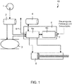
- FIG. 1 shows a compressed air device 10 for an air suspension of a motor vehicle 20 according to an embodiment of the invention.
- the compressed air device 10 here comprises a compressed air generating device 1 in the form of a piston compressor, a first storage container 2 for storing compressed air and an air bellows 3.
- the first storage container 2 is supplied with compressed air by the compressed air generating device 1 and the one air spring bellows 3 is removed from the first storage container 2 supplied with compressed air.
- the compressed air device 10 further comprises air bellows 3 (not shown), all of which can be mounted, for example, to change the level of the motor vehicle 20 between the respective vehicle axles and the vehicle body and can allow the vehicle body to be lowered and / or raised relative to the road.
- the motor vehicle 20 is also particularly preferably an omnibus.
- the compressed air device 10 comprises a second storage container 4 for storing compressed air, a compressed air-operated consumer 5 - in the present case in the form of a drive device for opening and / or closing a door 21 of the motor vehicle 20 - and an electro-pneumatic control device 6
- a pneumatic module 6a with electrically controllable pneumatic valves (not shown) and an electronics module 6b for controlling these valves can be enclosed in a common housing.
- the pneumatic module 6a is also connected via pneumatic delivery lines, which can also be referred to as compressed air lines, with the first and second storage containers 2, 4, the at least one air bellows 3, the compressed air-operated consumer 5 and an exhaust air line 8 and is designed to distribute compressed air between these components by means of the electrically controllable valves.
- the electronic module 6b of the electro-pneumatic control device 6 can also receive vehicle data and / or sensor data and / or control signals via an interface 7 in order to then distribute compressed air on the basis of this information.
- the electronic module 6b - and thus in particular the electro-pneumatic control device 6 - can receive sensor data relating to a compressed air quantity and / or an internal pressure of the first and / or second storage container 2, 4.
- the electro-pneumatic control device 6 can also receive a control signal for venting the air bellows 3 and / or a control signal for moving the compressed air-operated consumer 5 - in the present case the drive device for opening and / or closing a door 21 of the motor vehicle 20.
- the drive device is designed as a pneumatic piston-cylinder device, which is reversibly and continuously movable into a first and a second position, a change between the first and second position taking place in each case by supplying compressed air to the drive unit.
- the drive unit is connected to the pneumatic module 6a at two locations each via a pneumatic delivery line.
- the pneumatic piston-cylinder device can also include other components that are not explicitly shown, including seals, bearings, guide bands, magnets, etc.
- the compressed air device 10 itself can also comprise further components, such as check valves, air dryers, filters, temperature regulators, etc., which are conventional for such systems and are therefore not shown explicitly.
- the supply of compressed air from the second storage container 4 to the drive device is controlled in the present case via the electro-pneumatic control device 6.
- compressed air is admitted to a first region of the double-acting cylinder via a first compressed air line, as a result of which a piston which is mounted in the cylinder and is connected by means of a door mechanism (not shown) can be moved.
- the electro-pneumatic control device 6 can additionally supply compressed air from the first storage container 2 to the drive device. This advantageously enables efficient and needs-based use of the compressed air present in the system to be achieved.
- Figure 2 shows a compressed air device 10 for an air suspension of a motor vehicle 20 according to a further embodiment of the invention.
- the compressed air-operated consumer 5 is a vehicle seat, in particular a pneumatic seat suspension of a vehicle seat.
- the pneumatic seat suspension of the vehicle seat is also operated by means of compressed air previously "recycled" from the air bellows 3.
- fuel and / or energy that would otherwise have to be used to generate the compressed air for the vehicle seat can advantageously be saved.
- the embodiment shown consists in the size of the second storage container 4. This is designed to be smaller than the first storage container 2. In other words, the second storage container 4 has a smaller filling volume than the first storage container 2. However, the second storage container 4 can also be designed identically (as shown in FIG. 1) to the first storage container 2 or have a larger filling volume than the first storage container 2. Additionally or alternatively, the second storage container 4 can also differ in construction from the first storage container 2. For example, the second storage container 4 can be a spare wheel of the motor vehicle.
- the electro-pneumatic control module 6 is designed in the form of a separate pneumatic module 6a and a separate electronics module 6b, which are not encased in a common housing, but are connected via corresponding communication lines and can thereby exchange control signals, for example.
- the general operating mode of the electro-pneumatic control module 6 does not differ from that in FIG Figure 1 described case.
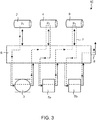
- Figure 3 shows a schematic representation of the compressed air flow F in a compressed air device 10 for an air suspension of a motor vehicle 20 according to a third “multi-stage” embodiment of the invention.
- this comprises three storage containers 2, 4, 9, which are referred to below as the first, second and third storage containers 2, 4, 9.
- the three storage containers 2, 4, 9 have different pressure levels p 1 , p 2 , p 3 , the pressure level of the first storage container p 1 preferably being greater than that of the second storage container p 2 and in turn larger than that of the third storage container p 3 can be.
- the average pressure in the first reservoir p 1 15 bar
- the average pressure in the second reservoir p 2 10 bar
- the average pressure in the third reservoir p 3 5 bar.
- other distributions of the compressed air levels p 1 , p 2 , p 3 can also be present in the storage containers 2, 4, 9 and / or further storage containers can be present in the compressed air device 10 without leaving the scope of the invention.
- the storage containers 2, 4, 9 can also each be connected to further piston compressors and / or compressors.
- the compressed air device 10 further comprises an air bellows, preferably for changing the level of the motor vehicle 20, and two compressed air-operated consumers 5a, 5b, which are referred to below as the first and second compressed-air operated consumers 5a, 5b.
- the first compressed air-operated consumer 5a can be, for example, a stop brake
- the second compressed-air-operated consumer 5b can be, for example, a transmission with shift support.
- the various components are connected via corresponding compressed air lines to an electro-pneumatic control device 6, which in turn can comprise a pneumatic module 6a and an electronics module 6b.
- the air bellows 3 is first filled with compressed air from the first reservoir 2 until the air bellows 3 reaches its normal position.
- exhaust air in the present case is fed at least in part to the second reservoir 4 via the electro-pneumatic control device 6.
- the first compressed air-operated consumer 5a for example a stop brake, can then be supplied with compressed air, which was previously used to fill the air bellows 3.
- the exhaust air which arises when the first compressed air-operated consumer 5a is subsequently emptied, for example when the stop brake is released, can then be fed to the third reservoir 9 via the electro-pneumatic control device 6.
- the compressed air collected there and thus already “recycled” twice can then in turn be used to operate the second consumer 5b actuated by compressed air, for example a transmission with shift support.
- the exhaust air generated when the second compressed air-operated consumer 5b is emptied is finally released to the atmosphere via an exhaust air line 8 and is therefore no longer available for further use in the motor vehicle 20.
- overall a "multi-stage" recycling of compressed air and thus a saving of resources, fuel and / or energy is achieved.
- the compressed air device 10 can also comprise further “recycle stages" without leaving the scope of the invention.
- Figure 4 shows a motor vehicle 20 with a compressed air device 10 for an air suspension according to an embodiment of the invention.
- the motor vehicle is an omnibus, preferably a city bus.
- the compressed air device 10 is preferably set up here to supply compressed air to the air suspension bellows 3 for leveling the motor vehicle 20, for example in the course of “kneeling” operations at stops, and the exhaust air which arises when the air suspension bellows 3 is emptied to supply a drive device for opening and / or or closing a door 21 of the motor vehicle 20.
- FIG. 5 shows a method for operating a compressed air device 10 for an air suspension of a motor vehicle 20 according to an embodiment of the invention.
- the compressed air device 10 comprises a compressed air generating device 1, for example a piston compressor and / or a compressor, at least one air bellows 3 and a first and second storage container 2, 4 for storing compressed air.
- the at least one air bellows 3 is filled with compressed air from the first storage container 2. If the vehicle comprises several air bellows, all can be in step S1 Vehicle air bellows 3 available, but only some of the air bellows 3 can be filled with compressed air.
- step S2 the at least one air bellows 3 is then emptied by discharging at least a portion of the compressed air from the at least one air bellows 3 into the second storage container 4.
- the expression “deflate” can mean both a complete and only a partial deflation of the air bellows 3.
- the at least one air bellows 3 can be contracted with the second storage container 4 via corresponding compressed air lines.
- the compressed air device 10 also includes a compressed air operated consumer 5, for example in the form of a pneumatic actuator, the at least one compressed air operated consumer 5 can be supplied with compressed air from the second reservoir 4 in a step S3.
Landscapes
- Engineering & Computer Science (AREA)
- Mechanical Engineering (AREA)
- Vehicle Body Suspensions (AREA)
Applications Claiming Priority (1)
| Application Number | Priority Date | Filing Date | Title |
|---|---|---|---|
| DE102018118939.7A DE102018118939A1 (de) | 2018-08-03 | 2018-08-03 | Druckluftvorrichtung für eine Luftfederung eines Kraftfahrzeugs, Kraftfahrzeug und Verfahren zum Betrieb einer Druckluftvorrichtung |
Publications (3)
| Publication Number | Publication Date |
|---|---|
| EP3616947A2 true EP3616947A2 (fr) | 2020-03-04 |
| EP3616947A3 EP3616947A3 (fr) | 2020-04-15 |
| EP3616947B1 EP3616947B1 (fr) | 2024-07-10 |
Family
ID=67514403
Family Applications (1)
| Application Number | Title | Priority Date | Filing Date |
|---|---|---|---|
| EP19189384.1A Active EP3616947B1 (fr) | 2018-08-03 | 2019-07-31 | Dispositif d'air comprimé pour une suspension pneumatique d'un véhicule automobile, véhicule automobile et procédé de fonctionnement d'un dispositif d'air comprimé |
Country Status (2)
| Country | Link |
|---|---|
| EP (1) | EP3616947B1 (fr) |
| DE (1) | DE102018118939A1 (fr) |
Cited By (1)
| Publication number | Priority date | Publication date | Assignee | Title |
|---|---|---|---|---|
| CN116044717A (zh) * | 2022-12-08 | 2023-05-02 | 山东泰展机电科技股份有限公司 | 车用空气泵增压系统及其循环增压方法 |
Families Citing this family (3)
| Publication number | Priority date | Publication date | Assignee | Title |
|---|---|---|---|---|
| DE102022101139A1 (de) | 2022-01-19 | 2023-07-20 | Zf Cv Systems Global Gmbh | Sensorreinigungssystem, pneumatisches System, Fahrzeug, Verfahren zum Betreiben eines pneumatischen Systems |
| DE102022101138A1 (de) | 2022-01-19 | 2023-07-20 | Zf Cv Systems Global Gmbh | Sensorreinigungssystem, pneumatisches System, Entlüftungs-Anschlussstutzen, Fahrzeug, Verfahren |
| CN121346180A (zh) * | 2024-07-15 | 2026-01-16 | 精达科技(安徽)有限公司 | 一种乘用车气动马达系统 |
Family Cites Families (5)
| Publication number | Priority date | Publication date | Assignee | Title |
|---|---|---|---|---|
| DE19515895A1 (de) * | 1995-04-29 | 1996-10-31 | Bosch Gmbh Robert | Druckluft-Versorgungseinrichtung für Fahrzeug-Druckluftanlagen sowie Verfahren zum Steuern der Druckluft-Versorgungseinrichtung |
| DE10223257A1 (de) * | 2002-05-24 | 2003-12-18 | Volke Entwicklungsring Gmbh | Automatische Reifendruckregelung und Luftfederung |
| DE10357762A1 (de) * | 2003-07-28 | 2005-02-24 | Wabco Gmbh & Co.Ohg | Elektronische Druckluftanlage |
| DE202007011430U1 (de) * | 2007-08-16 | 2007-11-29 | Duchzick, Harald | Drucklufteinheit |
| SE538476C2 (en) * | 2014-09-29 | 2016-07-19 | Scania Cv Ab | Air supplying system in a vehicle provided with an air operated kneeling system |
-
2018
- 2018-08-03 DE DE102018118939.7A patent/DE102018118939A1/de active Pending
-
2019
- 2019-07-31 EP EP19189384.1A patent/EP3616947B1/fr active Active
Cited By (2)
| Publication number | Priority date | Publication date | Assignee | Title |
|---|---|---|---|---|
| CN116044717A (zh) * | 2022-12-08 | 2023-05-02 | 山东泰展机电科技股份有限公司 | 车用空气泵增压系统及其循环增压方法 |
| CN116044717B (zh) * | 2022-12-08 | 2023-10-24 | 山东泰展机电科技股份有限公司 | 一种车用空气泵增压系统的循环增压方法 |
Also Published As
| Publication number | Publication date |
|---|---|
| EP3616947A3 (fr) | 2020-04-15 |
| EP3616947B1 (fr) | 2024-07-10 |
| DE102018118939A1 (de) | 2020-02-06 |
Similar Documents
| Publication | Publication Date | Title |
|---|---|---|
| EP2794308B1 (fr) | Système de suspension pneumatique pour un véhicule automobile et procédé de commande dudit système | |
| EP3616947A2 (fr) | Dispositif d'air comprimé pour une suspension pneumatique d'un véhicule automobile, véhicule automobile et procédé de fonctionnement d'un dispositif d'air comprimé | |
| EP0363827A2 (fr) | Véhicule à boggie à frein électrohydraulique et suspension hydropneumatique | |
| DE102017011526A1 (de) | Druckluftversorgungsanlage zum Betreiben einer Pneumatikanlage, Verfahren und Fahrzeug | |
| DE102008051546B4 (de) | Luftfederanlage für einen Kraftwagen mit wenigstens einer Ventilanordnung für eine Liftachse des Kraftwagens | |
| DE3919438A1 (de) | Druckluftbetaetigbare einrichtung mit einem zwischen einer druckmittelquelle und verbrauchern befindlichem lufttrockner | |
| EP2106937B1 (fr) | Véhicule utilitaire doté d'un ressort à gaz, notamment ressort pneumatique et système de ressort à gaz | |
| EP4406790B1 (fr) | Véhicule automobile comprenant un dispositif de fourniture d'eau d'essuie-glace | |
| DE102020108654A1 (de) | Lufttrockneranordnung, Druckluftversorgungsanlage, Verfahren zum Betreiben einer Druckluftversorgungsanlage, Pneumatisches System | |
| WO2023165832A1 (fr) | Procédé de fonctionnement d'un système pneumatique, et système pneumatique comprenant une installation d'alimentation en air comprimé et une installation de ressort pneumatique | |
| DE102017208213A1 (de) | Reifendruckregelsystem eines Fahrzeugs | |
| EP3705322A1 (fr) | Procédé de régulation du niveau d'un véhicule à suspension pneumatique ainsi que dispositif associé | |
| DE10223257A1 (de) | Automatische Reifendruckregelung und Luftfederung | |
| DE102016124253A1 (de) | Luftfederanlage für einen Kraftwagen | |
| DE102021133412A1 (de) | Ventilanordnung und Verfahren zur Steuerung einer anhebbaren Schleppachse eines Anhängefahrzeuges | |
| DE102009026393A1 (de) | Luftfedersystem mit Druckluftmotor | |
| EP3672858B1 (fr) | Système d'amortisseur pneumatique pour un véhicule ferroviaire | |
| EP0459095B1 (fr) | Autobus, en particulier à plate-forme surbaissée | |
| EP1078784A2 (fr) | Systéme de régulation du niveau comportant un accumulateur pour un véhicule à ressorts pneumatiques | |
| WO2023165833A1 (fr) | Procédé pour faire fonctionner un système pneumatique, et système pneumatique avec système d'alimentation en air comprimé et système de ressort pneumatique | |
| DE202018005034U1 (de) | Luftfedersystem für ein Schienenfahrzeug | |
| DE102012009383A1 (de) | Luftfederung eines Nutzfahrzeugs mit Achslastumschaltung zwischen Hinterachse und Vor- oder Nachlaufachse | |
| DE102005019478B3 (de) | Überströmventil zum Einbau in eine Leitung einer Druckluftbremsanlage eines luftgefederten Kraftfahrzeuges | |
| DE102010064460B4 (de) | Niveauregelanlage | |
| EP2848438A1 (fr) | Dispositif de ressort pneumatique pour un véhicule doté d'un moteur à combustion interne |
Legal Events
| Date | Code | Title | Description |
|---|---|---|---|
| PUAI | Public reference made under article 153(3) epc to a published international application that has entered the european phase |
Free format text: ORIGINAL CODE: 0009012 |
|
| STAA | Information on the status of an ep patent application or granted ep patent |
Free format text: STATUS: THE APPLICATION HAS BEEN PUBLISHED |
|
| AK | Designated contracting states |
Kind code of ref document: A2 Designated state(s): AL AT BE BG CH CY CZ DE DK EE ES FI FR GB GR HR HU IE IS IT LI LT LU LV MC MK MT NL NO PL PT RO RS SE SI SK SM TR |
|
| AX | Request for extension of the european patent |
Extension state: BA ME |
|
| PUAL | Search report despatched |
Free format text: ORIGINAL CODE: 0009013 |
|
| AK | Designated contracting states |
Kind code of ref document: A3 Designated state(s): AL AT BE BG CH CY CZ DE DK EE ES FI FR GB GR HR HU IE IS IT LI LT LU LV MC MK MT NL NO PL PT RO RS SE SI SK SM TR |
|
| AX | Request for extension of the european patent |
Extension state: BA ME |
|
| RIC1 | Information provided on ipc code assigned before grant |
Ipc: B60G 17/015 20060101ALI20200306BHEP Ipc: B60G 17/018 20060101ALI20200306BHEP Ipc: B60G 17/052 20060101ALI20200306BHEP Ipc: B60G 11/27 20060101AFI20200306BHEP Ipc: B60G 11/30 20060101ALI20200306BHEP Ipc: B60G 17/017 20060101ALI20200306BHEP |
|
| STAA | Information on the status of an ep patent application or granted ep patent |
Free format text: STATUS: REQUEST FOR EXAMINATION WAS MADE |
|
| 17P | Request for examination filed |
Effective date: 20201006 |
|
| RBV | Designated contracting states (corrected) |
Designated state(s): AL AT BE BG CH CY CZ DE DK EE ES FI FR GB GR HR HU IE IS IT LI LT LU LV MC MK MT NL NO PL PT RO RS SE SI SK SM TR |
|
| STAA | Information on the status of an ep patent application or granted ep patent |
Free format text: STATUS: EXAMINATION IS IN PROGRESS |
|
| 17Q | First examination report despatched |
Effective date: 20220725 |
|
| GRAP | Despatch of communication of intention to grant a patent |
Free format text: ORIGINAL CODE: EPIDOSNIGR1 |
|
| STAA | Information on the status of an ep patent application or granted ep patent |
Free format text: STATUS: GRANT OF PATENT IS INTENDED |
|
| INTG | Intention to grant announced |
Effective date: 20240216 |
|
| GRAS | Grant fee paid |
Free format text: ORIGINAL CODE: EPIDOSNIGR3 |
|
| GRAA | (expected) grant |
Free format text: ORIGINAL CODE: 0009210 |
|
| STAA | Information on the status of an ep patent application or granted ep patent |
Free format text: STATUS: THE PATENT HAS BEEN GRANTED |
|
| AK | Designated contracting states |
Kind code of ref document: B1 Designated state(s): AL AT BE BG CH CY CZ DE DK EE ES FI FR GB GR HR HU IE IS IT LI LT LU LV MC MK MT NL NO PL PT RO RS SE SI SK SM TR |
|
| REG | Reference to a national code |
Ref country code: CH Ref legal event code: EP |
|
| REG | Reference to a national code |
Ref country code: DE Ref legal event code: R096 Ref document number: 502019011615 Country of ref document: DE |
|
| REG | Reference to a national code |
Ref country code: SE Ref legal event code: TRGR |
|
| REG | Reference to a national code |
Ref country code: LT Ref legal event code: MG9D |
|
| REG | Reference to a national code |
Ref country code: NL Ref legal event code: MP Effective date: 20240710 |
|
| PG25 | Lapsed in a contracting state [announced via postgrant information from national office to epo] |
Ref country code: PT Free format text: LAPSE BECAUSE OF FAILURE TO SUBMIT A TRANSLATION OF THE DESCRIPTION OR TO PAY THE FEE WITHIN THE PRESCRIBED TIME-LIMIT Effective date: 20241111 |
|
| PG25 | Lapsed in a contracting state [announced via postgrant information from national office to epo] |
Ref country code: NL Free format text: LAPSE BECAUSE OF FAILURE TO SUBMIT A TRANSLATION OF THE DESCRIPTION OR TO PAY THE FEE WITHIN THE PRESCRIBED TIME-LIMIT Effective date: 20240710 |
|
| PG25 | Lapsed in a contracting state [announced via postgrant information from national office to epo] |
Ref country code: PT Free format text: LAPSE BECAUSE OF FAILURE TO SUBMIT A TRANSLATION OF THE DESCRIPTION OR TO PAY THE FEE WITHIN THE PRESCRIBED TIME-LIMIT Effective date: 20241111 Ref country code: NL Free format text: LAPSE BECAUSE OF FAILURE TO SUBMIT A TRANSLATION OF THE DESCRIPTION OR TO PAY THE FEE WITHIN THE PRESCRIBED TIME-LIMIT Effective date: 20240710 |
|
| PG25 | Lapsed in a contracting state [announced via postgrant information from national office to epo] |
Ref country code: NO Free format text: LAPSE BECAUSE OF FAILURE TO SUBMIT A TRANSLATION OF THE DESCRIPTION OR TO PAY THE FEE WITHIN THE PRESCRIBED TIME-LIMIT Effective date: 20241010 |
|
| PG25 | Lapsed in a contracting state [announced via postgrant information from national office to epo] |
Ref country code: GR Free format text: LAPSE BECAUSE OF FAILURE TO SUBMIT A TRANSLATION OF THE DESCRIPTION OR TO PAY THE FEE WITHIN THE PRESCRIBED TIME-LIMIT Effective date: 20241011 Ref country code: FI Free format text: LAPSE BECAUSE OF FAILURE TO SUBMIT A TRANSLATION OF THE DESCRIPTION OR TO PAY THE FEE WITHIN THE PRESCRIBED TIME-LIMIT Effective date: 20240710 Ref country code: PL Free format text: LAPSE BECAUSE OF FAILURE TO SUBMIT A TRANSLATION OF THE DESCRIPTION OR TO PAY THE FEE WITHIN THE PRESCRIBED TIME-LIMIT Effective date: 20240710 |
|
| PG25 | Lapsed in a contracting state [announced via postgrant information from national office to epo] |
Ref country code: BG Free format text: LAPSE BECAUSE OF FAILURE TO SUBMIT A TRANSLATION OF THE DESCRIPTION OR TO PAY THE FEE WITHIN THE PRESCRIBED TIME-LIMIT Effective date: 20240710 |
|
| PG25 | Lapsed in a contracting state [announced via postgrant information from national office to epo] |
Ref country code: LV Free format text: LAPSE BECAUSE OF FAILURE TO SUBMIT A TRANSLATION OF THE DESCRIPTION OR TO PAY THE FEE WITHIN THE PRESCRIBED TIME-LIMIT Effective date: 20240710 |
|
| PG25 | Lapsed in a contracting state [announced via postgrant information from national office to epo] |
Ref country code: IS Free format text: LAPSE BECAUSE OF FAILURE TO SUBMIT A TRANSLATION OF THE DESCRIPTION OR TO PAY THE FEE WITHIN THE PRESCRIBED TIME-LIMIT Effective date: 20241110 |
|
| PG25 | Lapsed in a contracting state [announced via postgrant information from national office to epo] |
Ref country code: HR Free format text: LAPSE BECAUSE OF FAILURE TO SUBMIT A TRANSLATION OF THE DESCRIPTION OR TO PAY THE FEE WITHIN THE PRESCRIBED TIME-LIMIT Effective date: 20240710 |
|
| PG25 | Lapsed in a contracting state [announced via postgrant information from national office to epo] |
Ref country code: ES Free format text: LAPSE BECAUSE OF FAILURE TO SUBMIT A TRANSLATION OF THE DESCRIPTION OR TO PAY THE FEE WITHIN THE PRESCRIBED TIME-LIMIT Effective date: 20240710 Ref country code: RS Free format text: LAPSE BECAUSE OF FAILURE TO SUBMIT A TRANSLATION OF THE DESCRIPTION OR TO PAY THE FEE WITHIN THE PRESCRIBED TIME-LIMIT Effective date: 20241010 |
|
| PG25 | Lapsed in a contracting state [announced via postgrant information from national office to epo] |
Ref country code: RS Free format text: LAPSE BECAUSE OF FAILURE TO SUBMIT A TRANSLATION OF THE DESCRIPTION OR TO PAY THE FEE WITHIN THE PRESCRIBED TIME-LIMIT Effective date: 20241010 Ref country code: PL Free format text: LAPSE BECAUSE OF FAILURE TO SUBMIT A TRANSLATION OF THE DESCRIPTION OR TO PAY THE FEE WITHIN THE PRESCRIBED TIME-LIMIT Effective date: 20240710 Ref country code: NO Free format text: LAPSE BECAUSE OF FAILURE TO SUBMIT A TRANSLATION OF THE DESCRIPTION OR TO PAY THE FEE WITHIN THE PRESCRIBED TIME-LIMIT Effective date: 20241010 Ref country code: LV Free format text: LAPSE BECAUSE OF FAILURE TO SUBMIT A TRANSLATION OF THE DESCRIPTION OR TO PAY THE FEE WITHIN THE PRESCRIBED TIME-LIMIT Effective date: 20240710 Ref country code: IS Free format text: LAPSE BECAUSE OF FAILURE TO SUBMIT A TRANSLATION OF THE DESCRIPTION OR TO PAY THE FEE WITHIN THE PRESCRIBED TIME-LIMIT Effective date: 20241110 Ref country code: HR Free format text: LAPSE BECAUSE OF FAILURE TO SUBMIT A TRANSLATION OF THE DESCRIPTION OR TO PAY THE FEE WITHIN THE PRESCRIBED TIME-LIMIT Effective date: 20240710 Ref country code: GR Free format text: LAPSE BECAUSE OF FAILURE TO SUBMIT A TRANSLATION OF THE DESCRIPTION OR TO PAY THE FEE WITHIN THE PRESCRIBED TIME-LIMIT Effective date: 20241011 Ref country code: FI Free format text: LAPSE BECAUSE OF FAILURE TO SUBMIT A TRANSLATION OF THE DESCRIPTION OR TO PAY THE FEE WITHIN THE PRESCRIBED TIME-LIMIT Effective date: 20240710 Ref country code: ES Free format text: LAPSE BECAUSE OF FAILURE TO SUBMIT A TRANSLATION OF THE DESCRIPTION OR TO PAY THE FEE WITHIN THE PRESCRIBED TIME-LIMIT Effective date: 20240710 Ref country code: BG Free format text: LAPSE BECAUSE OF FAILURE TO SUBMIT A TRANSLATION OF THE DESCRIPTION OR TO PAY THE FEE WITHIN THE PRESCRIBED TIME-LIMIT Effective date: 20240710 |
|
| REG | Reference to a national code |
Ref country code: CH Ref legal event code: PL |
|
| PG25 | Lapsed in a contracting state [announced via postgrant information from national office to epo] |
Ref country code: LU Free format text: LAPSE BECAUSE OF NON-PAYMENT OF DUE FEES Effective date: 20240731 |
|
| PG25 | Lapsed in a contracting state [announced via postgrant information from national office to epo] |
Ref country code: LU Free format text: LAPSE BECAUSE OF NON-PAYMENT OF DUE FEES Effective date: 20240731 |
|
| REG | Reference to a national code |
Ref country code: DE Ref legal event code: R097 Ref document number: 502019011615 Country of ref document: DE |
|
| PG25 | Lapsed in a contracting state [announced via postgrant information from national office to epo] |
Ref country code: SM Free format text: LAPSE BECAUSE OF FAILURE TO SUBMIT A TRANSLATION OF THE DESCRIPTION OR TO PAY THE FEE WITHIN THE PRESCRIBED TIME-LIMIT Effective date: 20240710 Ref country code: DK Free format text: LAPSE BECAUSE OF FAILURE TO SUBMIT A TRANSLATION OF THE DESCRIPTION OR TO PAY THE FEE WITHIN THE PRESCRIBED TIME-LIMIT Effective date: 20240710 Ref country code: RO Free format text: LAPSE BECAUSE OF FAILURE TO SUBMIT A TRANSLATION OF THE DESCRIPTION OR TO PAY THE FEE WITHIN THE PRESCRIBED TIME-LIMIT Effective date: 20240710 |
|
| PG25 | Lapsed in a contracting state [announced via postgrant information from national office to epo] |
Ref country code: BE Free format text: LAPSE BECAUSE OF NON-PAYMENT OF DUE FEES Effective date: 20240731 Ref country code: MC Free format text: LAPSE BECAUSE OF FAILURE TO SUBMIT A TRANSLATION OF THE DESCRIPTION OR TO PAY THE FEE WITHIN THE PRESCRIBED TIME-LIMIT Effective date: 20240710 Ref country code: CH Free format text: LAPSE BECAUSE OF NON-PAYMENT OF DUE FEES Effective date: 20240731 Ref country code: EE Free format text: LAPSE BECAUSE OF FAILURE TO SUBMIT A TRANSLATION OF THE DESCRIPTION OR TO PAY THE FEE WITHIN THE PRESCRIBED TIME-LIMIT Effective date: 20240710 |
|
| PG25 | Lapsed in a contracting state [announced via postgrant information from national office to epo] |
Ref country code: CZ Free format text: LAPSE BECAUSE OF FAILURE TO SUBMIT A TRANSLATION OF THE DESCRIPTION OR TO PAY THE FEE WITHIN THE PRESCRIBED TIME-LIMIT Effective date: 20240710 |
|
| PG25 | Lapsed in a contracting state [announced via postgrant information from national office to epo] |
Ref country code: SK Free format text: LAPSE BECAUSE OF FAILURE TO SUBMIT A TRANSLATION OF THE DESCRIPTION OR TO PAY THE FEE WITHIN THE PRESCRIBED TIME-LIMIT Effective date: 20240710 Ref country code: IT Free format text: LAPSE BECAUSE OF FAILURE TO SUBMIT A TRANSLATION OF THE DESCRIPTION OR TO PAY THE FEE WITHIN THE PRESCRIBED TIME-LIMIT Effective date: 20240710 |
|
| PLBE | No opposition filed within time limit |
Free format text: ORIGINAL CODE: 0009261 |
|
| STAA | Information on the status of an ep patent application or granted ep patent |
Free format text: STATUS: NO OPPOSITION FILED WITHIN TIME LIMIT |
|
| REG | Reference to a national code |
Ref country code: BE Ref legal event code: MM Effective date: 20240731 |
|
| 26N | No opposition filed |
Effective date: 20250411 |
|
| GBPC | Gb: european patent ceased through non-payment of renewal fee |
Effective date: 20241010 |
|
| PG25 | Lapsed in a contracting state [announced via postgrant information from national office to epo] |
Ref country code: GB Free format text: LAPSE BECAUSE OF NON-PAYMENT OF DUE FEES Effective date: 20241010 |
|
| PG25 | Lapsed in a contracting state [announced via postgrant information from national office to epo] |
Ref country code: IE Free format text: LAPSE BECAUSE OF NON-PAYMENT OF DUE FEES Effective date: 20240731 |
|
| REG | Reference to a national code |
Ref country code: AT Ref legal event code: MM01 Ref document number: 1701752 Country of ref document: AT Kind code of ref document: T Effective date: 20240731 |
|
| PGFP | Annual fee paid to national office [announced via postgrant information from national office to epo] |
Ref country code: DE Payment date: 20250728 Year of fee payment: 7 |
|
| PGFP | Annual fee paid to national office [announced via postgrant information from national office to epo] |
Ref country code: TR Payment date: 20250721 Year of fee payment: 7 |
|
| PG25 | Lapsed in a contracting state [announced via postgrant information from national office to epo] |
Ref country code: AT Free format text: LAPSE BECAUSE OF NON-PAYMENT OF DUE FEES Effective date: 20240731 |
|
| PGFP | Annual fee paid to national office [announced via postgrant information from national office to epo] |
Ref country code: FR Payment date: 20250725 Year of fee payment: 7 |
|
| PGFP | Annual fee paid to national office [announced via postgrant information from national office to epo] |
Ref country code: SE Payment date: 20250725 Year of fee payment: 7 |
|
| PG25 | Lapsed in a contracting state [announced via postgrant information from national office to epo] |
Ref country code: CY Free format text: LAPSE BECAUSE OF FAILURE TO SUBMIT A TRANSLATION OF THE DESCRIPTION OR TO PAY THE FEE WITHIN THE PRESCRIBED TIME-LIMIT; INVALID AB INITIO Effective date: 20190731 |
|
| PG25 | Lapsed in a contracting state [announced via postgrant information from national office to epo] |
Ref country code: HU Free format text: LAPSE BECAUSE OF FAILURE TO SUBMIT A TRANSLATION OF THE DESCRIPTION OR TO PAY THE FEE WITHIN THE PRESCRIBED TIME-LIMIT; INVALID AB INITIO Effective date: 20190731 |