EP3616988B1 - Dispositif d'éclairage pour un moyen de transport de personnes et / ou marchandises, composant d'habillage pour un moyen de transport de personnes et / ou marchandises doté d'un tel dispositif d'éclairage ainsi que moyen de transport de personnes et / ou marchandises doté d'un tel composant d'habillage - Google Patents
Dispositif d'éclairage pour un moyen de transport de personnes et / ou marchandises, composant d'habillage pour un moyen de transport de personnes et / ou marchandises doté d'un tel dispositif d'éclairage ainsi que moyen de transport de personnes et / ou marchandises doté d'un tel composant d'habillage Download PDFInfo
- Publication number
- EP3616988B1 EP3616988B1 EP18190887.2A EP18190887A EP3616988B1 EP 3616988 B1 EP3616988 B1 EP 3616988B1 EP 18190887 A EP18190887 A EP 18190887A EP 3616988 B1 EP3616988 B1 EP 3616988B1
- Authority
- EP
- European Patent Office
- Prior art keywords
- lighting device
- support element
- accordance
- passenger
- light source
- Prior art date
- Legal status (The legal status is an assumption and is not a legal conclusion. Google has not performed a legal analysis and makes no representation as to the accuracy of the status listed.)
- Active
Links
Images

Classifications
-
- F—MECHANICAL ENGINEERING; LIGHTING; HEATING; WEAPONS; BLASTING
- F21—LIGHTING
- F21S—NON-PORTABLE LIGHTING DEVICES; SYSTEMS THEREOF; VEHICLE LIGHTING DEVICES SPECIALLY ADAPTED FOR VEHICLE EXTERIORS
- F21S43/00—Signalling devices specially adapted for vehicle exteriors, e.g. brake lamps, direction indicator lights or reversing lights
- F21S43/30—Signalling devices specially adapted for vehicle exteriors, e.g. brake lamps, direction indicator lights or reversing lights characterised by reflectors
- F21S43/33—Signalling devices specially adapted for vehicle exteriors, e.g. brake lamps, direction indicator lights or reversing lights characterised by reflectors characterised by their material, surface treatment or coatings
-
- B—PERFORMING OPERATIONS; TRANSPORTING
- B60—VEHICLES IN GENERAL
- B60Q—ARRANGEMENT OF SIGNALLING OR LIGHTING DEVICES, THE MOUNTING OR SUPPORTING THEREOF OR CIRCUITS THEREFOR, FOR VEHICLES IN GENERAL
- B60Q1/00—Arrangement of optical signalling or lighting devices, the mounting or supporting thereof or circuits therefor
- B60Q1/0029—Spatial arrangement
- B60Q1/0035—Spatial arrangement relative to the vehicle
-
- F—MECHANICAL ENGINEERING; LIGHTING; HEATING; WEAPONS; BLASTING
- F21—LIGHTING
- F21S—NON-PORTABLE LIGHTING DEVICES; SYSTEMS THEREOF; VEHICLE LIGHTING DEVICES SPECIALLY ADAPTED FOR VEHICLE EXTERIORS
- F21S43/00—Signalling devices specially adapted for vehicle exteriors, e.g. brake lamps, direction indicator lights or reversing lights
- F21S43/20—Signalling devices specially adapted for vehicle exteriors, e.g. brake lamps, direction indicator lights or reversing lights characterised by refractors, transparent cover plates, light guides or filters
- F21S43/235—Light guides
- F21S43/251—Light guides the light guides being used to transmit light from remote light sources
-
- F—MECHANICAL ENGINEERING; LIGHTING; HEATING; WEAPONS; BLASTING
- F21—LIGHTING
- F21S—NON-PORTABLE LIGHTING DEVICES; SYSTEMS THEREOF; VEHICLE LIGHTING DEVICES SPECIALLY ADAPTED FOR VEHICLE EXTERIORS
- F21S43/00—Signalling devices specially adapted for vehicle exteriors, e.g. brake lamps, direction indicator lights or reversing lights
- F21S43/30—Signalling devices specially adapted for vehicle exteriors, e.g. brake lamps, direction indicator lights or reversing lights characterised by reflectors
- F21S43/31—Optical layout thereof
-
- B—PERFORMING OPERATIONS; TRANSPORTING
- B60—VEHICLES IN GENERAL
- B60Q—ARRANGEMENT OF SIGNALLING OR LIGHTING DEVICES, THE MOUNTING OR SUPPORTING THEREOF OR CIRCUITS THEREFOR, FOR VEHICLES IN GENERAL
- B60Q1/00—Arrangement of optical signalling or lighting devices, the mounting or supporting thereof or circuits therefor
- B60Q1/26—Arrangement of optical signalling or lighting devices, the mounting or supporting thereof or circuits therefor the devices being primarily intended to indicate the vehicle, or parts thereof, or to give signals, to other traffic
- B60Q1/34—Arrangement of optical signalling or lighting devices, the mounting or supporting thereof or circuits therefor the devices being primarily intended to indicate the vehicle, or parts thereof, or to give signals, to other traffic for indicating change of drive direction
- B60Q1/38—Arrangement of optical signalling or lighting devices, the mounting or supporting thereof or circuits therefor the devices being primarily intended to indicate the vehicle, or parts thereof, or to give signals, to other traffic for indicating change of drive direction using immovably-mounted light sources, e.g. fixed flashing lamps
- B60Q1/381—Arrangement of optical signalling or lighting devices, the mounting or supporting thereof or circuits therefor the devices being primarily intended to indicate the vehicle, or parts thereof, or to give signals, to other traffic for indicating change of drive direction using immovably-mounted light sources, e.g. fixed flashing lamps with several light sources activated in sequence, e.g. to create a sweep effect
-
- B—PERFORMING OPERATIONS; TRANSPORTING
- B60—VEHICLES IN GENERAL
- B60Q—ARRANGEMENT OF SIGNALLING OR LIGHTING DEVICES, THE MOUNTING OR SUPPORTING THEREOF OR CIRCUITS THEREFOR, FOR VEHICLES IN GENERAL
- B60Q2400/00—Special features or arrangements of exterior signal lamps for vehicles
- B60Q2400/20—Multi-color single source or LED matrix, e.g. yellow blinker and red brake lamp generated by single lamp
-
- B—PERFORMING OPERATIONS; TRANSPORTING
- B60—VEHICLES IN GENERAL
- B60Q—ARRANGEMENT OF SIGNALLING OR LIGHTING DEVICES, THE MOUNTING OR SUPPORTING THEREOF OR CIRCUITS THEREFOR, FOR VEHICLES IN GENERAL
- B60Q2400/00—Special features or arrangements of exterior signal lamps for vehicles
- B60Q2400/30—Daytime running lights [DRL], e.g. circuits or arrangements therefor
-
- B—PERFORMING OPERATIONS; TRANSPORTING
- B60—VEHICLES IN GENERAL
- B60Q—ARRANGEMENT OF SIGNALLING OR LIGHTING DEVICES, THE MOUNTING OR SUPPORTING THEREOF OR CIRCUITS THEREFOR, FOR VEHICLES IN GENERAL
- B60Q2900/00—Features of lamps not covered by other groups in B60Q
- B60Q2900/40—Several lamps activated in sequence, e.g. sweep effect, progressive activation
-
- F—MECHANICAL ENGINEERING; LIGHTING; HEATING; WEAPONS; BLASTING
- F21—LIGHTING
- F21W—INDEXING SCHEME ASSOCIATED WITH SUBCLASSES F21K, F21L, F21S and F21V, RELATING TO USES OR APPLICATIONS OF LIGHTING DEVICES OR SYSTEMS
- F21W2103/00—Exterior vehicle lighting devices for signalling purposes
- F21W2103/20—Direction indicator lights
-
- F—MECHANICAL ENGINEERING; LIGHTING; HEATING; WEAPONS; BLASTING
- F21—LIGHTING
- F21W—INDEXING SCHEME ASSOCIATED WITH SUBCLASSES F21K, F21L, F21S and F21V, RELATING TO USES OR APPLICATIONS OF LIGHTING DEVICES OR SYSTEMS
- F21W2103/00—Exterior vehicle lighting devices for signalling purposes
- F21W2103/55—Daytime running lights [DRL]
-
- F—MECHANICAL ENGINEERING; LIGHTING; HEATING; WEAPONS; BLASTING
- F21—LIGHTING
- F21W—INDEXING SCHEME ASSOCIATED WITH SUBCLASSES F21K, F21L, F21S and F21V, RELATING TO USES OR APPLICATIONS OF LIGHTING DEVICES OR SYSTEMS
- F21W2104/00—Exterior vehicle lighting devices for decorative purposes
Definitions
- the present invention relates to a lighting device for a means of transporting people and/or goods. Furthermore, the invention relates to a cladding component for a means of passenger and/or goods transport with such a lighting device and a passenger and/or goods transport means with such a cladding component.
- the means of transporting people and/or goods is designed in particular as a vehicle, but can also be a ship, an airplane, a train or the like. If the invention is explained below in relation to vehicles, the statements also apply equally to other means of transporting people and/or goods such as ships, airplanes, trains or the like.
- Lighting devices are used in almost all means of passenger and/or goods transport to alert other road users to your presence and to avoid collisions. In vehicles in particular, the lighting devices also serve to illuminate the immediate surroundings in the dark.
- a lighting device is to be understood in particular as a lighting device which emits light into the surroundings of the means of passenger and/or goods transport and which is not used to illuminate the interior of the means of passenger and/or goods transport.
- the lighting devices that are particularly relevant here can therefore also be used as external lighting devices or referred to as perimeter lighting devices.
- the lighting devices are therefore arranged on surfaces of the means of passenger and/or goods transport that at least temporarily point outwards.
- Lighting devices pointing outwards temporarily can be arranged, for example, in the doors, door sills or tailgates and only point outwards when the doors or tailgates are open.
- the lighting devices, which are temporarily pointing outwards, are then used to illuminate the immediate surroundings of the means of passenger and/or goods transport. If the doors and tailgates are closed, the lighting devices that point temporarily outwards are usually switched off. However, even if they were switched on, they would not be able to illuminate the interior because they are covered by adjacent body parts and their light cannot reach the interior.
- Lighting devices as in the EP 3 184 363 A1 disclosed therefore do not relate to the lighting devices presented here. External lighting devices are, for example, from WO 2013/113728 A1 known.
- More lighting devices are from FR 3 055 690 A1 , the WO 2016/166 193 A2 , the JP 2015 209 104 A , the CN 103 994 387 A , the US 2015/258 931 A1 , the WO 2017/092 844 A1 , the JP 2009 043 488 A and the DE 10 2009 053 571 A1 known.
- the lighting devices are increasingly becoming a formative design element, via which brand-specific customization compared to vehicles from another manufacturer is possible.
- the freedom of design for the lighting devices has hitherto been comparatively severely restricted, so that they cannot be placed anywhere, in particular on the external cladding components how bumpers can be arranged.
- a major reason for this is the fact that the cladding components in many cases have a complex surface curvature that cannot be reproduced with the known lighting devices, or can only be reproduced with great effort.
- the increasing electrification of vehicles opens up new scope for design, in which the lighting devices can be used in a previously unknown way. Since, unlike internal combustion engines, electric motors no longer require ventilation grilles, the lighting devices can be arranged in the radiator grille, for example. However, they can still be provided, in particular for design reasons, but in this case they differ significantly from the air grilles used for internal combustion engines.
- the lighting devices can also be used in such applications, they must be adaptable to complex surface geometries in order to be integrated seamlessly into the surface of the relevant paneling component of the means of passenger and/or goods transport or into the surface of the means of passenger and/or goods transport itself can, the lighting devices themselves should only require a small amount of space. Known lighting devices cannot meet these requirements or cannot do so with justifiable effort.
- the object of one embodiment of the present invention is to specify a lighting device for a means of transporting people and/or goods, with which it is possible to simulate complex surface geometries using simple and inexpensive means, the lighting device itself should only take up a small amount of space. Furthermore, an embodiment and an embodiment of the present invention are based on the object of creating a cladding component with such a lighting device and a means of transporting people and/or goods with such a cladding component.
- One embodiment of the invention relates to a lighting device for a means of transporting people and/or goods, comprising a first support element, a transparent second support element, which is connected to the first support element to form a cavity, and at least one light source for providing light in the cavity, wherein the first support member has a first inner surface facing the second support member and the second support member has a second inner surface facing the first support member, the first inner surface is reflective or a reflective coating is applied to the first inner surface and a reflective coating is applied to the second inner surface reflective, transparent coating is applied.
- the aim is to design the first inner surface in such a way that as much light as possible is reflected, preferably to reflect the light completely.
- a partially reflective, transparent coating is to be understood as meaning a coating in which part of the light is reflected, but at the same time the other part can penetrate the coating. Due to the In the proposed configuration of the lighting device, at least part of the light introduced into the cavity is reflected back and forth between the first inner surface and the second inner surface. This creates a depth effect, also referred to as an infinity effect, although the lighting device and in particular the cavity can be designed to be very flat. The lighting device can therefore be constructed as a sandwich. Due to the possibility of designing the lighting device to be very flat and still providing good illumination, the proposed lighting device can also be attached in places, in particular on a vehicle, where it was previously not possible or only possible with great effort.
- Both the reflective coating and the partially reflective, transparent coating can be produced by reflective or partially reflective, transparent films, which can also be back-injected.
- the coatings can be applied to the first support element and the second support element using sputtering, PVD ("Physical Vapor Deposition"), CVD ("Chemical Vapor Deposition”) or other coating methods.
- the first support element and the second support element can be glued, clipped, screwed, riveted or welded to one another.
- the first inner surface is rotatable.
- at least part of the first support element is rotatably mounted and rotated by means of an actuator. This allows dynamic lighting effects to be achieved.
- the light source is arranged in the cavity. Because of the possibility that To arrange the light source in the cavity, the proposed lighting device can be kept very compact. In addition, no precautions have to be taken to introduce the light provided by it into the cavity. The complexity of the lighting device according to this embodiment is thus kept low.
- the light source can be arranged outside of the cavity and the lighting device can have an introduction section for introducing the light provided by the light source into the cavity.
- the introduction section must be provided in order to be able to introduce the light provided by the light source into the cavity, the distance between the first inner surface and the second inner surface can be kept very small because the cavity does not have to be dimensioned so large that the light source can be placed there.
- the lighting device can be designed to be very flat in the area of the two support elements and thus to save space.
- the introduction section can be designed as an opening in the first support element.
- the introduction section can be provided in a technically very simple and therefore inexpensive manner.
- the introduction section can be designed as a light guide.
- light guides it is possible to arrange the light source at a greater distance from the two support elements and from the cavity. Consequently, there is the possibility of arranging the light source where it makes sense from a manufacturing point of view.
- a further developed embodiment is characterized in that a number of connecting webs are arranged in the cavity, with which the first support element is connected to the second support element.
- the connecting webs act as a reinforcement of the lighting device in the area of the two support elements, so that these can be designed over a large area without losing their stability and without requiring more installation space.
- At least one light source is arranged on one of the connecting webs. This makes it possible to arrange the light sources in a distributed manner within the cavity, as a result of which more uniform illumination can be achieved.
- a further embodiment is characterized in that the first inner surface has a curvature.
- the curvature can be either convex or concave.
- the curvature should be designed in such a way that the light is scattered or focused in a targeted and perceptible manner. This allows the illumination to be changed in a targeted manner and, in particular, to be made more uniform. However, it can also be desired to set certain changes in light intensity, which is made possible with the curvature.
- the curvature can be variable.
- the first support element can be provided with a certain flexibility and interact with an actuator, which correspondingly deforms the first support element to provide the convex or concave curvature. This allows dynamic lighting effects to be created.
- a further developed embodiment is characterized in that the first inner surface can be moved towards and away from the second inner surface.
- at least part of the first support element can be movably mounted and can be moved by means of an actuator. This also allows dynamic lighting effects to be achieved.
- the second support element can have an outer surface facing away from the first support element, on which a transparent coating is applied.
- This transparent coating can, for example, be designed in such a way that it is resistant to stone chips, scratches and UV rays.
- a class A surface can be provided by means of the transparent coating, which can also be in the form of a film.
- the transparent coating With the transparent coating, light scattering can be influenced in a targeted manner, for example with areas of the outer surface of the second support element that do not have a transparent coating.
- engravings or other coatings can be applied to the outer surface and/or the transparent coating.
- an anti-reflection coating or film is applied to the outer surface from the outside in order to prevent glare.
- the transparent coating is adapted to the requirements of the exterior components.
- the transparent coating can be formed, for example, as a transparent clear lacquer.
- the first support element and the second support element consist of an injection-mouldable plastic.
- the proposed lighting device can be provided inexpensively in large numbers, so that the proposed lighting device can be mass-produced.
- the coatings can already be provided in the injection molding tool, for example by film back injection.
- the first support element and the second support element can be connected to one another by injection molding or back injection molding.
- one of the support elements can be overmolded around the other of the support elements.
- the plastic is colored and/or tinted. Due to the coloring and/or the tinting of the plastic, the transmittance is reduced, as a result of which a black panel effect can be produced, for example, with the black panel effect also being able to be produced analogously with other colors. When switched off, the light sources are not visible from the outside due to the reduced degree of transmission.
- One embodiment of the invention relates to an external paneling component for a means of passenger and/or goods transport, comprising at least one lighting device according to one of the previous embodiments.
- One embodiment of the invention relates to a means of transporting people and/or goods, comprising at least one paneling component according to the embodiment described above and/or at least one lighting device according to one of the previous embodiments.
- the present lighting device makes it possible to simulate complex surface geometries with simple and inexpensive means, to provide extensive illumination due to the depth effect and to take up only a small amount of space. Consequently, external cladding components with complex surface geometries can also be illuminated, with the first support element being able to be integrated seamlessly or almost seamlessly into the surface of the external cladding component. It is therefore possible to illuminate any external surface of the means of passenger and/or goods transport without having to change its external contour.
- the lighting device can optionally be integrated into one of the external paneling components or into another surface of the means of passenger and/or goods transport.
- the proposed lighting device can be integrated into the bumper, the tailgate or other body parts or used instead of cooling or ventilation grilles that are no longer required in electric vehicles, or at least not in the configuration used up to now.
- the outer surface of the proposed lighting device simultaneously represents the outer surface of the means of passenger and/or goods transport, in particular the vehicle.
- the design in particular of the vehicle can be designed more freely and thus improved.
- a depth effect and a more extensive illumination resulting therefrom are achieved despite a narrow and flat structure of the lighting device.
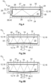
- FIG 1 a first exemplary embodiment of a lighting device 10 1 is shown using a basic sectional illustration.
- the lighting device 10 1 has an opaque first support element 12 which is approximately U-shaped and comprises a base section 14 and two legs 16 running perpendicular thereto.
- a flat, transparent second supporting element 18 is arranged between the two legs 16 and is connected to the first supporting element 12, for example by welding, overmolding, clipping, screwing, riveting or gluing.
- the two supporting elements 12, 18 form a cavity 20.
- a light source 22 is fastened to one of the legs 16 and partially protrudes into the cavity 20 .
- the base portion 14 of the first support member 12 forms a first inner surface 24 facing the second support member 18 .
- the second support element 18 forms one with the first support element 12 pointing second inner surface 26 and an outer surface 27 pointing away from the first support element 12.
- a reflective coating 28 is applied to the first inner surface 24 .
- the case in which the first inner surface 24 itself is designed to be reflective is not shown.
- the reflective properties of the first inner surface 24 can be produced, for example, with a high-gloss black surface (piano lacquer look).
- Such surfaces can be made, for example, by overmolding or flooding black or tinted plastics with a transparent plastic such as PMMA (polymethyl methacrylate) or PC (polycarbonate).
- the reflective property can also be produced without overmolding with a black or tinted plastic (for example tinted PC or PMMA with a high-gloss finish), as a result of which the coating or foiling of the first inner surface 24 can be saved.
- a partially reflective, transparent coating 30 is applied to the second inner surface 26 and a transparent coating 32 is applied to the outer surface 27 .
- the transparent coating 32 is not absolutely necessary and is used in particular when the plastic of the second support element 18 itself does not have the required properties as an exterior component, in particular with regard to stone impact, scratch and UV resistance or with regard to a class A surface.
- the arrangement of the reflective coating 28, the partially reflective, transparent coating 30 and the transparent coating 32 results in the following beam path P: Due to the fact that the light source 22 protrudes into the cavity 20, light is provided in the cavity 20. The light generated by the light source 22 and impinging on the reflective coating 28 is completely or almost completely reflected at the reflective coating 28 to form the partially reflective, transparent coating 30 . Part of the light penetrates the partially reflecting, transparent coating 30 and leaves the cavity 20. This part then penetrates the transparent second support element 18 and the transparent coating 32 and leaves the lighting device 10 1 . This part of the light is visible to a user from the outside. Another portion of the light reflects off the partially reflective, transparent coating 30 back into the cavity 20 to the reflective coating 28 .
- this portion is fully or almost fully reflected back to the partially reflective, transparent coating 30 , as already explained.
- This process is repeated many times, whereby the phenomena generated by the light source 22 are repeated and a depth effect is generated, also known as the infinity effect, although the distance between the two support elements 12, 18 only has to be large enough for the light source 22 to enter the cavity 20 can protrude.
- the transparent coating 32 can be tinted, for example to produce a "black panel effect".
- the black panel effect is preferably produced by the plastic itself being tinted or colored black (reduction in transmission). Alternatively, other colors such as red may be used in rear applications.
- a version with foil is also conceivable. In this case, the light source 22 cannot be seen from the outside when it is switched off; a homogeneous one appears black surface.
- an antireflection coating for example in the form of a film, is applied to the outer surface 27 in order to prevent glare.
- the light source 22 can be in the form of an LED or OLED and can be supplied with electrical energy via lines (not shown) and controlled by a control unit (also not shown). The color of the light emitted by the light source 22 can be changed. If the light source 22 is designed as an OLED, it can be printed onto the first support element 12, in particular when the first support element 12 consists of an injection-moldable plastic. However, the first support element 12 can also be overmolded around the light source 22 embodied as an OLED, or the light source 22 embodied in this way can be glued onto the first support element 22 . If the light source 22 is designed as an LED, it can be glued onto the first support element 12 or the first support element 12 can be injection molded around it.
- FIG 2 a second exemplary embodiment of the lighting device 10 2 is shown, which has a connecting web 34 .
- the first support element 12 is connected to the second support element 18 in the cavity 20 with the connecting web 34 .
- several connecting webs 34 can be provided, so that the first support element 12 and the second support element 18 can be connected to one another at several points.
- the connecting web 34 is designed in one piece with the first support element 12 and serves to support the second support element 18.
- a total of two light sources 22 are arranged on the connecting web 34.
- a light source 22 is fastened to each of the legs 16 of the first support element 12 .
- the light sources 22 can be controlled individually. For example, they can be switched on at different times so that a running light effect can be achieved. They can also light up in different colors, so that they function as indicators and as daytime running lights. Various lighting modes can be set.
- a further coating 36 is applied to the transparent coating 32 .
- the further coating 36 is transparent and can be in the form of an anti-reflective coating in order to prevent glare.
- the further coating 36 can be embodied as a transparent clear lacquer in order to increase the scratch resistance of the lighting device 10 2 .
- the additional coating 36 can then be dispensed with if the transparent layer 32 has the properties of the additional coating 36 .
- the further coating 36 can also be designed in such a way that the light sources 22 are not visible from the outside when switched off. For this purpose, parts of the additional coating 36 or the transparent coating 32 are opaque and can thus mask the light sources 22 .
- the further coating 36 can also be used to optically adapt the second support element 18 to the adjacent surface.
- FIG 3 a third exemplary embodiment of the lighting device 10 3 is shown.
- the light source 22 is arranged outside of the cavity 20 .
- an introduction section 38 is provided in order to be able to introduce the light provided by the light source 22 into the cavity 20, an introduction section 38 is provided.
- the introduction section 38 is designed as a light guide 40 which replaces one of the legs 16 of the first support element 12 .
- the light guide 40 is in particular on its surface pointing towards the cavity 20 convexly curved, so that the light beams are refracted towards one another and are thus introduced into the cavity 20 in a more or less bundled manner.
- the surface of the light guide 40 can be provided with different light decoupling structures, not shown here, in order, for example, to illuminate the edge regions of the lighting device 10 3 more homogeneously. This ensures that the largest possible part of the light provided by the light source 22 is introduced into the cavity 20 and the light is thus used effectively.
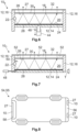
- FIG 4 a fourth exemplary embodiment of the lighting device 10 4 is shown.
- the light source 22 is also arranged outside of the cavity 20 in this exemplary embodiment.
- the introduction section 38 is designed as an opening 42 in the leg 16 of the first support element 12 that is arranged adjacent to the light source 22 .
- the light provided by the light source 22 traverses this opening 42 and then penetrates into the cavity 20 .
- the first inner surfaces 24 of the two legs 16 of the first support element 12 pointing towards the cavity 20 are also provided with the reflective coating 28 .
- the light impinging there is thrown back into the cavity 20 and can then leave the cavity 20 via the transparent second support element 18 .
- the light is therefore not absorbed by the legs 16 and is not lost.
- the lighting device 10 5 according to the fifth exemplary embodiment is essentially constructed in the same way as the lighting device 10 1 according to the first exemplary embodiment, but an actuator acts 44 with the base portion 14 of the first support member 12 together in the following manner.
- the actuator 44 has a plunger 46 which can be moved axially perpendicularly to the base section 14 and is firmly connected to the base section 14 . Depending on the direction in which the plunger 46 is moved, it elastically deforms the base section 14 . If the tappet 46, as in Figure 5A moved toward the second support member 18 as shown, the first support member 12 is deformed such that the first inner surface 24 has a convex curvature C. If the tappet 46, as in Figure 5B shown, is moved away from the second support member 18, the first support member 12 is deformed so that the first inner surface 24 has a concave c. This allows dynamic lighting effects to be created.
- figure 6 shows a sixth exemplary embodiment of the lighting device 10s.
- the base section 14 of the first support element 12 is fastened to the two legs 16 in an axially displaceable manner. Consequently, the base portion 14 can be slid toward and away from the second support member 18 .
- the actuator 44 described for the fifth exemplary embodiment can also be used in the sixth exemplary embodiment of the lighting device 10 6 in order to move the base section 14 towards the second support element 18 and away from it again. This allows dynamic lighting effects to be created.
- FIG 7 shows an exemplary embodiment of a lighting device 10 7 according to the invention.
- the base section 14 is rotatably mounted on the two legs 16 and can be rotated with a rotary actuator 48 about an axis of rotation T running perpendicular to the two legs 16 of the first support element 18 .
- This can also be used to create dynamic lighting effects.
- the lighting device 10 7 according to the seventh embodiment a screen 50, which covers the light source 22 so that it is not visible from the outside when switched off.
- engravings 52 are provided on the second support element 18 , which penetrate the transparent coating 32 and interrupt it in the area of the engravings 52 .
- the engravings 52 penetrate into the second support element 18, so that the light scattering is influenced.
- the light emitted by the lighting device 10 7 can thus be provided with certain patterns, for example the brand logo of the manufacturer of a means of passenger and/or goods transport 54.
- a means of transporting people and/or goods 54 is shown using a basic top view, which is designed as a vehicle 55 and has a total of three of the lighting devices 10 according to the invention.
- Two of the lighting devices 10 are arranged in an external trim component 56, which is designed here as a bumper.
- a third of the lighting devices 10 is arranged in the tailgate of the vehicle 55 .
- the outer surface 27 of the lighting device 10 1 forms part of the surface of the external trim component 56 or the tailgate 58.
- the outer surface 27 connects seamlessly or almost seamlessly to the surrounding surfaces of the vehicle 55.
Landscapes
- Engineering & Computer Science (AREA)
- General Engineering & Computer Science (AREA)
- Mechanical Engineering (AREA)
- Arrangements Of Lighting Devices For Vehicle Interiors, Mounting And Supporting Thereof, Circuits Therefore (AREA)
Claims (15)
- Dispositif d'éclairage (10) pour un moyen de transport de personnes et/ou de marchandises (54) comprenant :- un premier élément de support (12),- un second élément de support (18), transparent, relié au premier élément de support (12) en formant une cavité (20), et- au moins une source lumineuse (22) pour générer de la lumière dans la cavité (20),dispositif dans lequel- le premier élément de support (12) a une première surface intérieure (24) tournée vers le second élément de support (18), et- le second élément de support (18) a une seconde surface intérieure (26) orientée vers le premier élément de support (12),- la première surface intérieure (24) est réfléchissante ou encore un revêtement réfléchissant (28) est appliqué sur la première surface intérieure (12), et- un revêtement transparent, partiellement réfléchissant (30) est appliqué sur la seconde surface intérieure (26),dispositif caractérisé en ce que
la première surface intérieure (24) est rotative, et pour cela, au moins une partie du premier élément de support est monté à rotation en étant entraîné par un actionneur. - Dispositif d'éclairage selon la revendication 1,
caractérisé en ce que
la source lumineuse (22) est dans la cavité (20). - Dispositif d'éclairage selon la revendication 1,
caractérisé en ce que
la source lumineuse (22) est à l'extérieur de la cavité (20) et le dispositif d'éclairage (10) comporte un segment de guide d'entrée (38) pour diriger la lumière de la source lumineuse (22) dans la cavité (20). - Dispositif d'éclairage selon la revendication 3,
caractérisé en ce que
le segment de guide d'entrée (38) est constitué par un passage (42) dans le premier élément de support (12). - Dispositif d'éclairage selon la revendication 3,
caractérisé en ce que
le segment de guide d'entrée (38) est un guide de lumière (40). - Dispositif d'éclairage selon l'une des revendications précédentes, caractérisé en ce que
un certain nombre d'entretoises de liaison (34) sont prévues dans la cavité (20), ces entretoises reliant le premier élément de support (12) au second support (18). - Dispositif d'éclairage selon la revendication 6,
caractérisé en ce que
au moins une source lumineuse (22) est prévue pour l'une des entretoises de liaison (34). - Dispositif d'éclairage selon l'une des revendications précédentes, caractérisé en ce que
la première surface intérieure (24) a une bombure (C). - Dispositif d'éclairage selon la revendication 8,
caractérisé en ce que
la bombure (C) est variable. - Dispositif d'éclairage selon l'une des revendications précédentes, caractérisé en ce que
la première surface (24) est mobile en écartement par rapport à la seconde surface intérieure (26). - Dispositif d'éclairage selon l'une des revendications précédentes,
caractérisé en ce que
le second élément de support (18) a une première surface extérieure (27) non tournée vers le premier élément de support (12) et qui est munie d'un revêtement transparent (32). - Dispositif d'éclairage selon l'une des revendications précédentes,
caractérisé en ce que
le premier élément de support (12) et le second élément de support (18) sont en une matière plastique susceptible d'être injectée. - Dispositif d'éclairage selon la revendication 12,
caractérisé en ce que
la matière plastique est en couleur et/ou teintée. - Composant d'habillage externe pour un moyen de transport de personnes et/ou de marchandises (54) comprenant un dispositif d'éclairage (10) selon l'une des revendications précédentes.
- Moyen de transport de personnes et/ou de marchandises (54) comprenant au moins un composant d'habillage externe (56) selon la revendication 14 et/ou un dispositif d'éclairage (10) selon l'une des revendications 1 à 13.
Priority Applications (1)
| Application Number | Priority Date | Filing Date | Title |
|---|---|---|---|
| EP18190887.2A EP3616988B1 (fr) | 2018-08-27 | 2018-08-27 | Dispositif d'éclairage pour un moyen de transport de personnes et / ou marchandises, composant d'habillage pour un moyen de transport de personnes et / ou marchandises doté d'un tel dispositif d'éclairage ainsi que moyen de transport de personnes et / ou marchandises doté d'un tel composant d'habillage |
Applications Claiming Priority (1)
| Application Number | Priority Date | Filing Date | Title |
|---|---|---|---|
| EP18190887.2A EP3616988B1 (fr) | 2018-08-27 | 2018-08-27 | Dispositif d'éclairage pour un moyen de transport de personnes et / ou marchandises, composant d'habillage pour un moyen de transport de personnes et / ou marchandises doté d'un tel dispositif d'éclairage ainsi que moyen de transport de personnes et / ou marchandises doté d'un tel composant d'habillage |
Publications (2)
| Publication Number | Publication Date |
|---|---|
| EP3616988A1 EP3616988A1 (fr) | 2020-03-04 |
| EP3616988B1 true EP3616988B1 (fr) | 2023-05-31 |
Family
ID=63490208
Family Applications (1)
| Application Number | Title | Priority Date | Filing Date |
|---|---|---|---|
| EP18190887.2A Active EP3616988B1 (fr) | 2018-08-27 | 2018-08-27 | Dispositif d'éclairage pour un moyen de transport de personnes et / ou marchandises, composant d'habillage pour un moyen de transport de personnes et / ou marchandises doté d'un tel dispositif d'éclairage ainsi que moyen de transport de personnes et / ou marchandises doté d'un tel composant d'habillage |
Country Status (1)
| Country | Link |
|---|---|
| EP (1) | EP3616988B1 (fr) |
Families Citing this family (2)
| Publication number | Priority date | Publication date | Assignee | Title |
|---|---|---|---|---|
| CN114791095A (zh) * | 2021-01-08 | 2022-07-26 | 现代摩比斯株式会社 | 用于车辆的照明设备及其制造方法 |
| DE102024201235A1 (de) * | 2024-02-12 | 2025-08-14 | Stellantis Auto Sas | Leuchtvorrichtung für einen Innenraum eines Fahrzeugs |
Family Cites Families (10)
| Publication number | Priority date | Publication date | Assignee | Title |
|---|---|---|---|---|
| JP2009043488A (ja) * | 2007-08-07 | 2009-02-26 | Toyoda Gosei Co Ltd | リアコンビネーションランプ |
| DE102009053571B4 (de) * | 2009-11-06 | 2017-11-09 | Automotive Lighting Reutlingen Gmbh | Leuchte für Kraftfahrzeuge mit einem Spiegelsystem und einem Lichtleiter |
| FR2986604B1 (fr) | 2012-02-03 | 2015-07-31 | Automotive Lighting Rear Lamps France | Module d'eclairage a led pour feux arriere de vehicule automobile |
| KR101451861B1 (ko) * | 2014-03-14 | 2014-10-16 | 에스엘 주식회사 | 차량용 램프 |
| JP6279394B2 (ja) * | 2014-04-25 | 2018-02-14 | サカエ理研工業株式会社 | 車両用発光装置 |
| CN103994387B (zh) * | 2014-05-29 | 2017-01-04 | 长城汽车股份有限公司 | 车灯和具有它的汽车 |
| FR3035183B1 (fr) * | 2015-04-17 | 2018-10-12 | Valeo Vision | Dispositif d'eclairage ou de signalisation lumineuse a effet de profondeur |
| DE102015015841B4 (de) * | 2015-12-05 | 2022-01-13 | Daimler Ag | Leuchtenanordnung mit Heckleuchten und beleuchteter Zierleiste |
| ES2565877B1 (es) | 2015-12-24 | 2016-11-10 | Seat, S.A. | Dispositivo de iluminación para panel interior de vehículo |
| FR3055690B1 (fr) * | 2016-09-08 | 2020-06-26 | Faurecia Interieur Industrie | Structure retroeclairee pour vehicule |
-
2018
- 2018-08-27 EP EP18190887.2A patent/EP3616988B1/fr active Active
Also Published As
| Publication number | Publication date |
|---|---|
| EP3616988A1 (fr) | 2020-03-04 |
Similar Documents
| Publication | Publication Date | Title |
|---|---|---|
| EP1215081B1 (fr) | Feu pour véhicule | |
| EP3844028B1 (fr) | Dispositif d'éclairage destiné à un véhicule automobile | |
| DE102017214129A1 (de) | Radarfähiges Leuchtemblem für ein Fahrzeug | |
| WO2020239688A1 (fr) | Composant pouvant être rétroéclairé | |
| EP4143058B1 (fr) | Garniture interne pour véhicule | |
| EP3088156B1 (fr) | Procede de fabrication d'une piece rapportee pouvant etre eclairee, piece rapportee pouvant etre eclairee et vehicule automobile la comprenant | |
| DE102006048323A1 (de) | Außenrückblickspiegel für Fahrzeuge, vorzugsweise für Kraftfahrzeuge | |
| DE102012211822A1 (de) | Gehäuseschale für eine Leuchteneinheit eines Kraftfahrzeug und Verfahren zum Herstellen einer Gehäuseschale für eine Leuchteneinheit eines Kraftfahrzeug | |
| DE102019110238A1 (de) | Kraftfahrzeug mit einem Zier- oder Verkleidungsteil im Exterieurbereich | |
| DE102021003615A1 (de) | Beleuchtetes Bauteil für ein Fahrzeug | |
| DE202012007518U1 (de) | Hintergrundbeleuchtete Fahrzeug-Innenstruktur | |
| DE102012211821B4 (de) | Leuchteneinheit für ein Kraftfahrzeug, bei der in einer Gehäuseschale mit Fensterabschnitt Leuchtmittel angeordnet sind | |
| EP4344949B1 (fr) | Système d'éclairage pour un élément d'habillage extérieur d'un véhicule automobile | |
| EP3616988B1 (fr) | Dispositif d'éclairage pour un moyen de transport de personnes et / ou marchandises, composant d'habillage pour un moyen de transport de personnes et / ou marchandises doté d'un tel dispositif d'éclairage ainsi que moyen de transport de personnes et / ou marchandises doté d'un tel composant d'habillage | |
| DE102009025637A1 (de) | Versenkt angeordnetes, beleuchtetes, hochgesetzt und mittig montiertes Bremslicht (CHMSL) | |
| DE102020133087A1 (de) | Außenverkleidungsteil für ein Kraftfahrzeug und Verfahren zur Herstellung eines Außenverkleidungsteils für ein Kraftfahrzeug | |
| EP3792111A1 (fr) | Luminaire | |
| EP3814172B1 (fr) | Procédé de fabrication d'un module de clignotant ainsi que module de clignotant, système de rétroviseur et véhicule automobile | |
| WO2020161291A1 (fr) | Dispositif de caisse de carrosserie de véhicule | |
| DE19707614C2 (de) | Karosserieteil eines Kraftfahrzeuges | |
| DE102016216276A1 (de) | Innenraumverkleidung für ein Kraftfahrzeug | |
| EP3770016A1 (fr) | Dispositif d'éclairage pour un moyen de transport des personnes et / ou des marchandises ou pour un composant de revêtement externe ou interne d'un moyen de transport des personnes et / ou des marchandises, composant de revêtement externe ou interne ainsi que moyen de transport des personnes et / ou des marchandises doté d'un tel dispositif d'éclairage | |
| DE102024122423A1 (de) | Fahrzeug mit einem Fahrzeugfrontelement, insbesondere Frontpanel | |
| WO2014161675A1 (fr) | Dispositif d'éclairage d'une plaque d'immatriculation arrière d'un véhicule automobile | |
| DE102016214270A1 (de) | Blende zur Innenausstattung eines Kraftfahrzeugs, Verfahren zum Herstellen einer Blende und Kraftfahrzeug |
Legal Events
| Date | Code | Title | Description |
|---|---|---|---|
| PUAI | Public reference made under article 153(3) epc to a published international application that has entered the european phase |
Free format text: ORIGINAL CODE: 0009012 |
|
| STAA | Information on the status of an ep patent application or granted ep patent |
Free format text: STATUS: THE APPLICATION HAS BEEN PUBLISHED |
|
| AK | Designated contracting states |
Kind code of ref document: A1 Designated state(s): AL AT BE BG CH CY CZ DE DK EE ES FI FR GB GR HR HU IE IS IT LI LT LU LV MC MK MT NL NO PL PT RO RS SE SI SK SM TR |
|
| AX | Request for extension of the european patent |
Extension state: BA ME |
|
| STAA | Information on the status of an ep patent application or granted ep patent |
Free format text: STATUS: REQUEST FOR EXAMINATION WAS MADE |
|
| 17P | Request for examination filed |
Effective date: 20200429 |
|
| RBV | Designated contracting states (corrected) |
Designated state(s): AL AT BE BG CH CY CZ DE DK EE ES FI FR GB GR HR HU IE IS IT LI LT LU LV MC MK MT NL NO PL PT RO RS SE SI SK SM TR |
|
| STAA | Information on the status of an ep patent application or granted ep patent |
Free format text: STATUS: EXAMINATION IS IN PROGRESS |
|
| RIC1 | Information provided on ipc code assigned before grant |
Ipc: F21W 103/55 20180101ALI20220117BHEP Ipc: F21W 103/20 20180101ALI20220117BHEP Ipc: F21W 104/00 20180101ALI20220117BHEP Ipc: B60Q 1/38 20060101ALI20220117BHEP Ipc: F21S 43/33 20180101ALI20220117BHEP Ipc: F21S 43/31 20180101ALI20220117BHEP Ipc: F21S 43/251 20180101ALI20220117BHEP Ipc: B60R 13/00 20060101ALI20220117BHEP Ipc: B60Q 1/00 20060101AFI20220117BHEP |
|
| 17Q | First examination report despatched |
Effective date: 20220207 |
|
| RAP3 | Party data changed (applicant data changed or rights of an application transferred) |
Owner name: MOTHERSON INNOVATIONS COMPANY LIMITED |
|
| GRAP | Despatch of communication of intention to grant a patent |
Free format text: ORIGINAL CODE: EPIDOSNIGR1 |
|
| STAA | Information on the status of an ep patent application or granted ep patent |
Free format text: STATUS: GRANT OF PATENT IS INTENDED |
|
| INTG | Intention to grant announced |
Effective date: 20221209 |
|
| INTG | Intention to grant announced |
Effective date: 20230105 |
|
| GRAS | Grant fee paid |
Free format text: ORIGINAL CODE: EPIDOSNIGR3 |
|
| GRAA | (expected) grant |
Free format text: ORIGINAL CODE: 0009210 |
|
| STAA | Information on the status of an ep patent application or granted ep patent |
Free format text: STATUS: THE PATENT HAS BEEN GRANTED |
|
| AK | Designated contracting states |
Kind code of ref document: B1 Designated state(s): AL AT BE BG CH CY CZ DE DK EE ES FI FR GB GR HR HU IE IS IT LI LT LU LV MC MK MT NL NO PL PT RO RS SE SI SK SM TR |
|
| REG | Reference to a national code |
Ref country code: GB Ref legal event code: FG4D Free format text: NOT ENGLISH Ref country code: CH Ref legal event code: EP |
|
| P01 | Opt-out of the competence of the unified patent court (upc) registered |
Effective date: 20230427 |
|
| REG | Reference to a national code |
Ref country code: AT Ref legal event code: REF Ref document number: 1570749 Country of ref document: AT Kind code of ref document: T Effective date: 20230615 Ref country code: DE Ref legal event code: R096 Ref document number: 502018012205 Country of ref document: DE |
|
| REG | Reference to a national code |
Ref country code: IE Ref legal event code: FG4D Free format text: LANGUAGE OF EP DOCUMENT: GERMAN |
|
| REG | Reference to a national code |
Ref country code: LT Ref legal event code: MG9D |
|
| REG | Reference to a national code |
Ref country code: NL Ref legal event code: MP Effective date: 20230531 |
|
| PG25 | Lapsed in a contracting state [announced via postgrant information from national office to epo] |
Ref country code: SE Free format text: LAPSE BECAUSE OF FAILURE TO SUBMIT A TRANSLATION OF THE DESCRIPTION OR TO PAY THE FEE WITHIN THE PRESCRIBED TIME-LIMIT Effective date: 20230531 Ref country code: NO Free format text: LAPSE BECAUSE OF FAILURE TO SUBMIT A TRANSLATION OF THE DESCRIPTION OR TO PAY THE FEE WITHIN THE PRESCRIBED TIME-LIMIT Effective date: 20230831 Ref country code: ES Free format text: LAPSE BECAUSE OF FAILURE TO SUBMIT A TRANSLATION OF THE DESCRIPTION OR TO PAY THE FEE WITHIN THE PRESCRIBED TIME-LIMIT Effective date: 20230531 |
|
| PG25 | Lapsed in a contracting state [announced via postgrant information from national office to epo] |
Ref country code: RS Free format text: LAPSE BECAUSE OF FAILURE TO SUBMIT A TRANSLATION OF THE DESCRIPTION OR TO PAY THE FEE WITHIN THE PRESCRIBED TIME-LIMIT Effective date: 20230531 Ref country code: PL Free format text: LAPSE BECAUSE OF FAILURE TO SUBMIT A TRANSLATION OF THE DESCRIPTION OR TO PAY THE FEE WITHIN THE PRESCRIBED TIME-LIMIT Effective date: 20230531 Ref country code: NL Free format text: LAPSE BECAUSE OF FAILURE TO SUBMIT A TRANSLATION OF THE DESCRIPTION OR TO PAY THE FEE WITHIN THE PRESCRIBED TIME-LIMIT Effective date: 20230531 Ref country code: LV Free format text: LAPSE BECAUSE OF FAILURE TO SUBMIT A TRANSLATION OF THE DESCRIPTION OR TO PAY THE FEE WITHIN THE PRESCRIBED TIME-LIMIT Effective date: 20230531 Ref country code: LT Free format text: LAPSE BECAUSE OF FAILURE TO SUBMIT A TRANSLATION OF THE DESCRIPTION OR TO PAY THE FEE WITHIN THE PRESCRIBED TIME-LIMIT Effective date: 20230531 Ref country code: IS Free format text: LAPSE BECAUSE OF FAILURE TO SUBMIT A TRANSLATION OF THE DESCRIPTION OR TO PAY THE FEE WITHIN THE PRESCRIBED TIME-LIMIT Effective date: 20230930 Ref country code: HR Free format text: LAPSE BECAUSE OF FAILURE TO SUBMIT A TRANSLATION OF THE DESCRIPTION OR TO PAY THE FEE WITHIN THE PRESCRIBED TIME-LIMIT Effective date: 20230531 Ref country code: GR Free format text: LAPSE BECAUSE OF FAILURE TO SUBMIT A TRANSLATION OF THE DESCRIPTION OR TO PAY THE FEE WITHIN THE PRESCRIBED TIME-LIMIT Effective date: 20230901 |
|
| PG25 | Lapsed in a contracting state [announced via postgrant information from national office to epo] |
Ref country code: FI Free format text: LAPSE BECAUSE OF FAILURE TO SUBMIT A TRANSLATION OF THE DESCRIPTION OR TO PAY THE FEE WITHIN THE PRESCRIBED TIME-LIMIT Effective date: 20230531 |
|
| PG25 | Lapsed in a contracting state [announced via postgrant information from national office to epo] |
Ref country code: SK Free format text: LAPSE BECAUSE OF FAILURE TO SUBMIT A TRANSLATION OF THE DESCRIPTION OR TO PAY THE FEE WITHIN THE PRESCRIBED TIME-LIMIT Effective date: 20230531 |
|
| PG25 | Lapsed in a contracting state [announced via postgrant information from national office to epo] |
Ref country code: SM Free format text: LAPSE BECAUSE OF FAILURE TO SUBMIT A TRANSLATION OF THE DESCRIPTION OR TO PAY THE FEE WITHIN THE PRESCRIBED TIME-LIMIT Effective date: 20230531 Ref country code: SK Free format text: LAPSE BECAUSE OF FAILURE TO SUBMIT A TRANSLATION OF THE DESCRIPTION OR TO PAY THE FEE WITHIN THE PRESCRIBED TIME-LIMIT Effective date: 20230531 Ref country code: RO Free format text: LAPSE BECAUSE OF FAILURE TO SUBMIT A TRANSLATION OF THE DESCRIPTION OR TO PAY THE FEE WITHIN THE PRESCRIBED TIME-LIMIT Effective date: 20230531 Ref country code: PT Free format text: LAPSE BECAUSE OF FAILURE TO SUBMIT A TRANSLATION OF THE DESCRIPTION OR TO PAY THE FEE WITHIN THE PRESCRIBED TIME-LIMIT Effective date: 20231002 Ref country code: EE Free format text: LAPSE BECAUSE OF FAILURE TO SUBMIT A TRANSLATION OF THE DESCRIPTION OR TO PAY THE FEE WITHIN THE PRESCRIBED TIME-LIMIT Effective date: 20230531 Ref country code: DK Free format text: LAPSE BECAUSE OF FAILURE TO SUBMIT A TRANSLATION OF THE DESCRIPTION OR TO PAY THE FEE WITHIN THE PRESCRIBED TIME-LIMIT Effective date: 20230531 Ref country code: CZ Free format text: LAPSE BECAUSE OF FAILURE TO SUBMIT A TRANSLATION OF THE DESCRIPTION OR TO PAY THE FEE WITHIN THE PRESCRIBED TIME-LIMIT Effective date: 20230531 |
|
| REG | Reference to a national code |
Ref country code: DE Ref legal event code: R097 Ref document number: 502018012205 Country of ref document: DE |
|
| PG25 | Lapsed in a contracting state [announced via postgrant information from national office to epo] |
Ref country code: MC Free format text: LAPSE BECAUSE OF FAILURE TO SUBMIT A TRANSLATION OF THE DESCRIPTION OR TO PAY THE FEE WITHIN THE PRESCRIBED TIME-LIMIT Effective date: 20230531 |
|
| REG | Reference to a national code |
Ref country code: CH Ref legal event code: PL |
|
| PG25 | Lapsed in a contracting state [announced via postgrant information from national office to epo] |
Ref country code: MC Free format text: LAPSE BECAUSE OF FAILURE TO SUBMIT A TRANSLATION OF THE DESCRIPTION OR TO PAY THE FEE WITHIN THE PRESCRIBED TIME-LIMIT Effective date: 20230531 |
|
| PLBE | No opposition filed within time limit |
Free format text: ORIGINAL CODE: 0009261 |
|
| STAA | Information on the status of an ep patent application or granted ep patent |
Free format text: STATUS: NO OPPOSITION FILED WITHIN TIME LIMIT |
|
| PG25 | Lapsed in a contracting state [announced via postgrant information from national office to epo] |
Ref country code: LU Free format text: LAPSE BECAUSE OF NON-PAYMENT OF DUE FEES Effective date: 20230827 |
|
| GBPC | Gb: european patent ceased through non-payment of renewal fee |
Effective date: 20230831 |
|
| PG25 | Lapsed in a contracting state [announced via postgrant information from national office to epo] |
Ref country code: LU Free format text: LAPSE BECAUSE OF NON-PAYMENT OF DUE FEES Effective date: 20230827 Ref country code: CH Free format text: LAPSE BECAUSE OF NON-PAYMENT OF DUE FEES Effective date: 20230831 |
|
| PG25 | Lapsed in a contracting state [announced via postgrant information from national office to epo] |
Ref country code: SI Free format text: LAPSE BECAUSE OF FAILURE TO SUBMIT A TRANSLATION OF THE DESCRIPTION OR TO PAY THE FEE WITHIN THE PRESCRIBED TIME-LIMIT Effective date: 20230531 |
|
| REG | Reference to a national code |
Ref country code: BE Ref legal event code: MM Effective date: 20230831 |
|
| 26N | No opposition filed |
Effective date: 20240301 |
|
| REG | Reference to a national code |
Ref country code: IE Ref legal event code: MM4A |
|
| PG25 | Lapsed in a contracting state [announced via postgrant information from national office to epo] |
Ref country code: SI Free format text: LAPSE BECAUSE OF FAILURE TO SUBMIT A TRANSLATION OF THE DESCRIPTION OR TO PAY THE FEE WITHIN THE PRESCRIBED TIME-LIMIT Effective date: 20230531 Ref country code: IT Free format text: LAPSE BECAUSE OF FAILURE TO SUBMIT A TRANSLATION OF THE DESCRIPTION OR TO PAY THE FEE WITHIN THE PRESCRIBED TIME-LIMIT Effective date: 20230531 |
|
| PG25 | Lapsed in a contracting state [announced via postgrant information from national office to epo] |
Ref country code: IE Free format text: LAPSE BECAUSE OF NON-PAYMENT OF DUE FEES Effective date: 20230827 |
|
| PG25 | Lapsed in a contracting state [announced via postgrant information from national office to epo] |
Ref country code: GB Free format text: LAPSE BECAUSE OF NON-PAYMENT OF DUE FEES Effective date: 20230831 |
|
| PG25 | Lapsed in a contracting state [announced via postgrant information from national office to epo] |
Ref country code: IE Free format text: LAPSE BECAUSE OF NON-PAYMENT OF DUE FEES Effective date: 20230827 Ref country code: GB Free format text: LAPSE BECAUSE OF NON-PAYMENT OF DUE FEES Effective date: 20230831 Ref country code: FR Free format text: LAPSE BECAUSE OF NON-PAYMENT OF DUE FEES Effective date: 20230831 |
|
| PG25 | Lapsed in a contracting state [announced via postgrant information from national office to epo] |
Ref country code: BE Free format text: LAPSE BECAUSE OF NON-PAYMENT OF DUE FEES Effective date: 20230831 |
|
| REG | Reference to a national code |
Ref country code: AT Ref legal event code: MM01 Ref document number: 1570749 Country of ref document: AT Kind code of ref document: T Effective date: 20230827 |
|
| PG25 | Lapsed in a contracting state [announced via postgrant information from national office to epo] |
Ref country code: AT Free format text: LAPSE BECAUSE OF NON-PAYMENT OF DUE FEES Effective date: 20230827 |
|
| PG25 | Lapsed in a contracting state [announced via postgrant information from national office to epo] |
Ref country code: AT Free format text: LAPSE BECAUSE OF NON-PAYMENT OF DUE FEES Effective date: 20230827 |
|
| PG25 | Lapsed in a contracting state [announced via postgrant information from national office to epo] |
Ref country code: BG Free format text: LAPSE BECAUSE OF FAILURE TO SUBMIT A TRANSLATION OF THE DESCRIPTION OR TO PAY THE FEE WITHIN THE PRESCRIBED TIME-LIMIT Effective date: 20230531 |
|
| PG25 | Lapsed in a contracting state [announced via postgrant information from national office to epo] |
Ref country code: BG Free format text: LAPSE BECAUSE OF FAILURE TO SUBMIT A TRANSLATION OF THE DESCRIPTION OR TO PAY THE FEE WITHIN THE PRESCRIBED TIME-LIMIT Effective date: 20230531 |
|
| PG25 | Lapsed in a contracting state [announced via postgrant information from national office to epo] |
Ref country code: CY Free format text: LAPSE BECAUSE OF FAILURE TO SUBMIT A TRANSLATION OF THE DESCRIPTION OR TO PAY THE FEE WITHIN THE PRESCRIBED TIME-LIMIT; INVALID AB INITIO Effective date: 20180827 |
|
| PG25 | Lapsed in a contracting state [announced via postgrant information from national office to epo] |
Ref country code: HU Free format text: LAPSE BECAUSE OF FAILURE TO SUBMIT A TRANSLATION OF THE DESCRIPTION OR TO PAY THE FEE WITHIN THE PRESCRIBED TIME-LIMIT; INVALID AB INITIO Effective date: 20180827 |
|
| PGFP | Annual fee paid to national office [announced via postgrant information from national office to epo] |
Ref country code: DE Payment date: 20250819 Year of fee payment: 8 |
|
| PG25 | Lapsed in a contracting state [announced via postgrant information from national office to epo] |
Ref country code: TR Free format text: LAPSE BECAUSE OF FAILURE TO SUBMIT A TRANSLATION OF THE DESCRIPTION OR TO PAY THE FEE WITHIN THE PRESCRIBED TIME-LIMIT Effective date: 20230531 |