EP3617065B1 - Hauptrotorblatt und hubschrauber - Google Patents
Hauptrotorblatt und hubschrauber Download PDFInfo
- Publication number
- EP3617065B1 EP3617065B1 EP18791962.6A EP18791962A EP3617065B1 EP 3617065 B1 EP3617065 B1 EP 3617065B1 EP 18791962 A EP18791962 A EP 18791962A EP 3617065 B1 EP3617065 B1 EP 3617065B1
- Authority
- EP
- European Patent Office
- Prior art keywords
- blade
- main rotor
- main body
- main
- rotor blade
- Prior art date
- Legal status (The legal status is an assumption and is not a legal conclusion. Google has not performed a legal analysis and makes no representation as to the accuracy of the status listed.)
- Active
Links
Images

Classifications
-
- B—PERFORMING OPERATIONS; TRANSPORTING
- B64—AIRCRAFT; AVIATION; COSMONAUTICS
- B64C—AEROPLANES; HELICOPTERS
- B64C27/00—Rotorcraft; Rotors peculiar thereto
- B64C27/32—Rotors
- B64C27/46—Blades
- B64C27/463—Blade tips
-
- B—PERFORMING OPERATIONS; TRANSPORTING
- B64—AIRCRAFT; AVIATION; COSMONAUTICS
- B64C—AEROPLANES; HELICOPTERS
- B64C27/00—Rotorcraft; Rotors peculiar thereto
- B64C27/04—Helicopters
-
- B—PERFORMING OPERATIONS; TRANSPORTING
- B64—AIRCRAFT; AVIATION; COSMONAUTICS
- B64C—AEROPLANES; HELICOPTERS
- B64C27/00—Rotorcraft; Rotors peculiar thereto
- B64C27/32—Rotors
- B64C27/46—Blades
- B64C27/467—Aerodynamic features
-
- B—PERFORMING OPERATIONS; TRANSPORTING
- B64—AIRCRAFT; AVIATION; COSMONAUTICS
- B64C—AEROPLANES; HELICOPTERS
- B64C27/00—Rotorcraft; Rotors peculiar thereto
- B64C27/32—Rotors
- B64C27/46—Blades
- B64C27/473—Constructional features
-
- F—MECHANICAL ENGINEERING; LIGHTING; HEATING; WEAPONS; BLASTING
- F01—MACHINES OR ENGINES IN GENERAL; ENGINE PLANTS IN GENERAL; STEAM ENGINES
- F01D—NON-POSITIVE DISPLACEMENT MACHINES OR ENGINES, e.g. STEAM TURBINES
- F01D5/00—Blades; Blade-carrying members; Heating, heat-insulating, cooling or antivibration means on the blades or the members
- F01D5/12—Blades
- F01D5/14—Form or construction
-
- F—MECHANICAL ENGINEERING; LIGHTING; HEATING; WEAPONS; BLASTING
- F01—MACHINES OR ENGINES IN GENERAL; ENGINE PLANTS IN GENERAL; STEAM ENGINES
- F01D—NON-POSITIVE DISPLACEMENT MACHINES OR ENGINES, e.g. STEAM TURBINES
- F01D5/00—Blades; Blade-carrying members; Heating, heat-insulating, cooling or antivibration means on the blades or the members
- F01D5/30—Fixing blades to rotors; Blade roots ; Blade spacers
-
- F—MECHANICAL ENGINEERING; LIGHTING; HEATING; WEAPONS; BLASTING
- F05—INDEXING SCHEMES RELATING TO ENGINES OR PUMPS IN VARIOUS SUBCLASSES OF CLASSES F01-F04
- F05D—INDEXING SCHEME FOR ASPECTS RELATING TO NON-POSITIVE-DISPLACEMENT MACHINES OR ENGINES, GAS-TURBINES OR JET-PROPULSION PLANTS
- F05D2220/00—Application
- F05D2220/90—Application in vehicles adapted for vertical or short take off and landing (v/stol vehicles)
-
- F—MECHANICAL ENGINEERING; LIGHTING; HEATING; WEAPONS; BLASTING
- F05—INDEXING SCHEMES RELATING TO ENGINES OR PUMPS IN VARIOUS SUBCLASSES OF CLASSES F01-F04
- F05D—INDEXING SCHEME FOR ASPECTS RELATING TO NON-POSITIVE-DISPLACEMENT MACHINES OR ENGINES, GAS-TURBINES OR JET-PROPULSION PLANTS
- F05D2240/00—Components
- F05D2240/20—Rotors
- F05D2240/30—Characteristics of rotor blades, i.e. of any element transforming dynamic fluid energy to or from rotational energy and being attached to a rotor
- F05D2240/307—Characteristics of rotor blades, i.e. of any element transforming dynamic fluid energy to or from rotational energy and being attached to a rotor related to the tip of a rotor blade
Definitions
- the present invention relates to a main rotor blade used for a high-velocity helicopter such as an ambulance helicopter, for example.
- the present invention further relates to a helicopter including the main rotor blade.
- upper and lower main rotor blades are provided coaxially, the upper main rotor blades are rotated in one direction and the lower main rotor blades are rotated in the opposite direction, and an anti torque is thereby balanced.
- a main blade type high-velocity helicopter has propellers at the both sides of a main blade, and an anti torque of the main rotor blade is thereby generated.
- EP 0 866 765 A1 describes a rotor system having odd and even blade assemblies mounting to and rotating with a rotor hub assembly wherein the odd blade assemblies define a radial length RO, and the even blade assemblies define a radial length RE and wherein the radial length RE is between about 70 % to about 95 % of the radial length RO.
- US 1 692 081 A describes an aircraft in which the supporting surfaces are constituted by freely rotative wings driven by the relative air flow in flight and to hinge-jointed to the axis of rotation, a wing formation, in which the chord is relatively small in the part nearest the root, increases to a maximum in the outer half of the wing's length, and thence again decreases towards the tip.
- US6497385 B1 discloses a rotor blade for a rotary-wing aircraft, and more particularly, a blade with an increased hover figure of merit as compared to known blades.
- a main rotor blade for a helicopter such as a main blade type helicopter, which may reduce a drag coefficient during high-velocity forward flight and which provides easy control. It is an object of the present invention to provide a helicopter including such a main rotor blade.
- a main rotor blade according to an embodiment of the present invention is a main rotor blade for a high-velocity helicopter including: a blade root part having a length of 30% or more of a rotor radius; and a blade main body continuous with the blade root part.
- the blade cross-sectional shape of the blade root part is different from a blade cross-sectional shape of a normal blade type.
- the leading edge and the trailing edge have round shapes.
- a region called back flow region is enlarged at a backward drag side of a main rotor blade.
- Increase of a collective pitch angle to cope with the enlarged back flow region will reduce a thrust force, to the contrary.
- the back flow region is a region in which the mainstream flows from a trailing edge side to a leading edge side of a main rotor blade.
- the larger the back flow region the larger the drag coefficient during high-velocity forward flight and the more difficult the control, in addition.
- the large back flow region will increase difficulty of control because of the following reason. Since a mainstream flows from a trailing edge of a blade in a back flow region, a negative lift force is generated, whereas a positive lift force is generated normally.
- a blade root part has a length of 30% or more of a rotor radius.
- the range of a blade having a blade shape in a back flow region is small.
- the blade root part is thin in the blade thickness direction and, in addition, the entire body has a smooth shape. This shape may reduce the drag coefficient during high-velocity forward flight.
- a chord length of the blade main body has a maximum value at a position in a range of 50% to 90% of a rotor radius, and the maximum value is 1.6 times to 1.8 times as long as a reference chord length of an interface part between the blade root part and the blade main body.
- the hovering performance (figure of merit) of the main rotor blade is similar to or is higher than the hovering performance (figure of merit) of a normal helicopter. At the same time, it is possible to reduce the drag coefficient during high-velocity forward flight.
- a torsion angle of the blade main body has a minimum value at a position in a range of 80% to 95% of a rotor radius, and is gradually reduced from a blade root side and from a blade tip side to the position.
- the hovering performance (figure of merit) of the main rotor blade is higher than the hovering performance (figure of merit) of a normal helicopter. At the same time, it is possible to reduce the drag coefficient during high-velocity forward flight.
- a blade tip of the blade main body has a hedral angle of -30° to 30°.
- a hedral angle is provided in order to increase a hovering performance, the drag coefficient during high-velocity forward flight may be increased.
- the blade tip of the blade main body having a hedral angle (anhedral angle or dihedral angle) of -30° to 30° may prevent extreme increase of the drag coefficient, and may increase the hovering performance.
- a chord length of a blade tip of the blade main body is 30% or less of a reference chord length of an interface part between the blade root part and the blade main body.
- a larger Mach number generates shock waves and high-velocity shock sounds as a result, which are problems.
- the blade tip of the blade main body having a chord length of 30% or less of a reference chord length may reduce generation of shock waves on the blade tip during high-velocity forward flight.
- a blade tip of the blade main body has a swept-back angle of 60° or less.
- the blade tip of the blade main body having a swept-back angle of 60° or less may reduce generation of a shock wave at the blade tip during high-velocity forward flight, similar to the above.
- a helicopter includes: the main rotor blade having the aforementioned structure.
- the present invention it is possible to reduce a drag coefficient during high-velocity forward flight and provide easy control for a helicopter such as a main blade type helicopter.
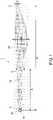
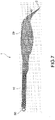
- Fig. 1 is a perspective view showing a structure of a main rotor blade according to an embodiment of the present invention.
- the main rotor blade 1 includes the blade root part 10 and the blade main body 20. Note that, here, it is supposed that the main rotor blade 1 is used for a helicopter with supposed flight conditions of hovering and high-velocity flight of the forward thrust rate of 0.8.
- the main rotor blade 1 is used for a main blade type helicopter.
- the blade root part 10 is a part of the main rotor blade 1, which is at a blade root side, does not have a blade-shaped cross-sectional shape, and mainly plays a role of an architecture without generating a lift force.
- the length A of the blade root part 10 is 30% to 60% of the rotor radius R, and is more preferably 40% of the rotor radius R.
- the rotor radius R is a length from the center of rotation 31 of the rotor 30 of a helicopter to the blade tip 2 of the main rotor blade 1.
- the blade main body 20 is structured continuous with the blade root part 10, and is a part of the main rotor blade 1 of a helicopter, which has a blade-shaped cross-sectional shape and generates a lift force.
- Fig. 2 shows a cross-sectional shape of the blade root part 10.
- Fig. 3 is a graph showing a chord length of the blade main body 20.
- the chord length B of the blade main body 20 has the maximum value Bmax at a position in a range of 50% to 90% of the rotor radius R.
- the maximum value is 1.6 times to 2.0 times and more preferably 1.8 times as long as the reference chord length C of the interface part (root cut out part) 3 between the blade root part 10 and the blade main body 20.
- chord length B of the blade main body 20 is once increased as the chord comes closer to the blade tip 2, and the chord length B of the part at the blade tip 2 is extremely short.
- the chord length D of the blade tip 2 of the blade main body 20 is 30% or less of and more preferably 20% of the reference chord length C of the interface part 3.
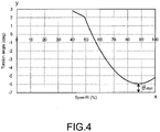
- the torsion angle ⁇ of the blade main body 20 has a minimum value at a position in a range of 80% to 95% of the rotor radius R, and is gradually reduced from the side of the blade root 4 and from the blade tip 2 to the position of the minimum value.
- the torsion angle ⁇ of the blade main body 20 at a position slightly deviated from the blade tip 2 to the side of the blade root 4 (for example, position of about 90% of the rotor radius R) once has the minimum value ⁇ min , and the torsion angle ⁇ of the blade tip 2 is slightly larger than that.
- the torsion angle of the main rotor blade 1 is the angle of the blade airfoil at each span position from the blade root part to the blade tip part of the blade.
- the streamwise velocity of the blade airfoil differs depending on the span position from the blade root part to the blade tip part of a helicopter. In view of that fact, provision of the torsion angle in the span direction will generate a lift force at each span position with an appropriate angle of attack.
- chord length B and the torsion angle ⁇ on the span of the main rotor blade 1 by using polynomials allows to select one of a case where adjacent segments are continuous via the junction point therebetween, or a case where adjacent segments are not continuous via the junction point therebetween.
- a polynomial derivative (n-1)th formula may be used.
- a formula other than that may be used.
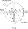
- Fig. 5 is a diagram illustrating a fact that a back flow region is generated at the backward drag side of the main rotor blade 1.
- Fig. 5 is a top view of the main rotor blade 1, which is rotating. The main rotor blade 1 rotates in the anticlockwise direction in Fig. 5 , and the forward thrust direction of the helicopter is the upward direction of Fig. 5 .
- the horizontal flight velocity (V) balances the rotation velocity (r ⁇ ) in the rotor radius direction r.
- the direction of the horizontal flight velocity (V) is totally opposite to the direction of the rotation velocity (r ⁇ ) in the rotor radius direction r.
- the relationship between the horizontal flight velocity (V) and the rotation velocity (r ⁇ ) is inverted such that the horizontal flight velocity (V) > the rotation velocity (rQ) is satisfied.
- the mainstream flow direction is changed such that the mainstream flows from the trailing edge side to the leading edge side of the main rotor blade 1.
- the back flow region 60 may be generated from the position 61 to the center of rotation 31 of the rotor 30. Especially, the closer to the center of rotation 31 of the rotor 30, the larger the effect of a reverse thrust force due to the horizontal flight velocity (V). In addition, the higher the velocity, the larger the effect of the reverse thrust force due to the horizontal flight velocity (V).
- the length A of the blade root part 10, which is not affected by the reverse thrust force due to the horizontal flight velocity (V) is long. As a result, the back flow region 60 is not generated in a part close to the blade root 4. As a result, the drag coefficient during high-velocity forward flight can be reduced. Further, also, control is not difficult because a negative lift force is not likely to be generated in the back flow region.
- the distance between the position 61, at which the back flow region 60 starts, and the center of rotation 31 of the rotor 30 is R ⁇ (R: rotor radius, ⁇ : forward thrust rate).
- R rotor radius
- ⁇ forward thrust rate
- the length A of the blade root part 10 of the main rotor blade 1 is 1/2 of R ⁇ .
- chord length B of the blade main body 20 of the main rotor blade 1 has the maximum value Bmax at a position in a range of 50% to 90% of the rotor radius R.
- the maximum value Bmax is 1.6 times to 2.0 times as long as the reference chord length C.
- the torsion angle ⁇ of the blade main body 20 at a position slightly deviated from the blade tip 2 to the side of the blade root 4 once has the minimum value ⁇ min , and the torsion angle ⁇ of the blade tip 2 is slightly larger than that.
- the figure of merit of the main rotor blade 1 is not reduced and, at the same time, the drag coefficient may be reduced.
- the figure of merit of the main rotor blade 1 having the blade main body 20 of such a shape is higher than the figure of merit of a conventional flat-plate-like main rotor blade (constant chord length and constant torsion angle).
- the drag coefficient of the main rotor blade 1 having the blade main body 20 of such a shape is lower by about 15% than the drag coefficient of a conventional flat-plate-like main rotor blade (constant chord length and constant torsion angle).
- the blade root part 10 of the main rotor blade 1 having the cross-sectional shape shown in Fig. 2 reduces the drag coefficient.
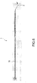
- the blade tip 2 of the blade main body 20 may have an anhedral angle or a dihedral angle.
- the blade tip 2 of the blade main body 20 has the anhedral angle of 30°.
- the range of a hedral angle is -30° to 30°. This range may increase the figure of merit during hovering. The reason is as follows. The distance between the blade tip and the blade main body is increased. As a result, a phenomenon, in which a blade tip vortex suddenly changes the lift force distribution on the blade, may be reduced. As a result, the induced velocity distribution on the rotor plane has an almost constant value.
- the blade tip 2 of the blade main body 20 may have a swept-back angle.
- the blade tip 2 of the blade main body 20 has a swept-back angle of 45°.
- the range of the swept-back angle is 60° or less. This range of the swept-back angle may prevent the drag coefficient from being increased. The reason is as follows. The mainstream component with respect to the blade is reduced. As a result, it is possible to prevent a drag force due to a shock wave from being increased.
- the blade tip of the blade main body having the swept-back blade may have an anhedral angle of Fig. 6 or a dihedral angle.
- the main rotor blade 1 is used for a main blade type helicopter.
- the main rotor blade of the present invention may be applicable for other types of helicopter.
- it is supposed that the main rotor blade 1 is used for a helicopter with supposed flight conditions of hovering and high-velocity flight of the forward thrust rate of 0.8.
- the forward thrust rate may be 0.8 or less, or 0.8 or more.
Landscapes
- Engineering & Computer Science (AREA)
- Mechanical Engineering (AREA)
- Aviation & Aerospace Engineering (AREA)
- General Engineering & Computer Science (AREA)
- Physics & Mathematics (AREA)
- Fluid Mechanics (AREA)
- Structures Of Non-Positive Displacement Pumps (AREA)
- Turbine Rotor Nozzle Sealing (AREA)
- Toys (AREA)
Claims (7)
- Hauptrotorblatt (1), mit:einem Blattwurzelteil (10) mit einer Länge von 30% oder mehr eines Rotorradius (R);einem mit dem Blattwurzelteil (10) zusammenhängend ausgebildeten Blatthauptkörper (20),dadurch gekennzeichnet, dassein Torsionswinkel des Blatthauptkörpers (20) einen Minimalwert (θmin) an einer Position in einem Bereich von 80% bis 95% eines Rotorradius (R) aufweist und von einer Blattwurzelseite und von einer Blattspitzen(2)seite zu der Position des Minimalwerts allmählich abnimmt.
- Hauptrotorblatt (1) nach dem vorhergehenden Anspruch, wobei
eine Querschnittsform des Blattwurzelteils (10) die Beziehung (x/a)m+(y/b)m = 1 erfüllt, wobei a > b ist,
wobeim: beliebige Zahl,x: Sehnenlängenrichtung, undy: Blattdickenrichtung. - Hauptrotorblatt (1) nach einem der vorhergehenden Ansprüche, wobei eine Sehnenlänge (B) des Blatthauptkörpers (20) einen Maximalwert (Bmax) an einer Position in einem Bereich von 50% bis 90% eines Rotorradius (R) hat, und der Maximalwert 1,6-mal bis 1,8-mal so lang wie eine Referenzsehnenlänge (C) eines Grenzflächenteils (3) zwischen dem Blattwurzelteil (10) und dem Blatthauptkörper (20) ist.
- Hauptrotorblatt (1) nach einem der vorhergehenden Ansprüche, wobei eine Blattspitze (2) des Blatthauptkörpers (20) einen Hedralwinkel von -30° bis 30° aufweist.
- Hauptrotorblatt (1) nach einem der Ansprüche 1 bis 4, wobei eine Sehnenlänge (D) einer Blattspitze (2) des Blatthauptkörpers (20) 30% oder weniger einer Referenzsehnenlänge (C) eines Grenzflächenteils (3) zwischen dem Blattwurzelteil (10) und dem Blatthauptkörper (20) beträgt.
- Hauptrotorblatt (1) nach einem der vorhergehenden Ansprüche, wobei
eine Blattspitze (2) des Blatthauptkörpers (20) einen Sweepback-Winkel von 60° oder weniger aufweist. - Hubschrauber mit:
dem Hauptrotorblatt (1) nach einem der vorhergehenden Ansprüche.
Applications Claiming Priority (2)
| Application Number | Priority Date | Filing Date | Title |
|---|---|---|---|
| JP2017086872A JP6980962B2 (ja) | 2017-04-26 | 2017-04-26 | メインロータブレード及びヘリコプタ |
| PCT/JP2018/004264 WO2018198477A1 (ja) | 2017-04-26 | 2018-02-07 | メインロータブレード及びヘリコプタ |
Publications (3)
| Publication Number | Publication Date |
|---|---|
| EP3617065A1 EP3617065A1 (de) | 2020-03-04 |
| EP3617065A4 EP3617065A4 (de) | 2021-01-13 |
| EP3617065B1 true EP3617065B1 (de) | 2022-11-02 |
Family
ID=63919747
Family Applications (1)
| Application Number | Title | Priority Date | Filing Date |
|---|---|---|---|
| EP18791962.6A Active EP3617065B1 (de) | 2017-04-26 | 2018-02-07 | Hauptrotorblatt und hubschrauber |
Country Status (4)
| Country | Link |
|---|---|
| US (1) | US11214364B2 (de) |
| EP (1) | EP3617065B1 (de) |
| JP (1) | JP6980962B2 (de) |
| WO (1) | WO2018198477A1 (de) |
Families Citing this family (5)
| Publication number | Priority date | Publication date | Assignee | Title |
|---|---|---|---|---|
| WO2019241725A1 (en) * | 2018-06-15 | 2019-12-19 | The Texas A&M University System | Hover-capable aircraft |
| JP7035940B2 (ja) | 2018-09-28 | 2022-03-15 | 株式会社Jvcケンウッド | ヘッドアップディスプレイ装置 |
| CN109573016B (zh) * | 2018-11-14 | 2021-02-26 | 中国直升机设计研究所 | 一种轻型无人直升机尾桨的桨叶气动外形 |
| KR102131562B1 (ko) * | 2019-07-05 | 2020-07-07 | 도레이첨단소재 주식회사 | 무인항공기용 섬유강화플라스틱 프로펠러 및 이의 제조방법 |
| US12448111B1 (en) * | 2024-04-17 | 2025-10-21 | Textron Innovations Inc. | Method and system for inverse-tapered high-speed rotors |
Citations (3)
| Publication number | Priority date | Publication date | Assignee | Title |
|---|---|---|---|---|
| EP0866765B1 (de) * | 1995-12-11 | 1999-05-12 | Sikorsky Aircraft Corporation | Rotorsystem mit unterschiedlichen blattlängen zur verminderung des lärmpegels von blattwirbeln |
| US6497385B1 (en) * | 2000-11-08 | 2002-12-24 | Continuum Dynamics, Inc. | Rotor blade with optimized twist distribution |
| EP1893483B1 (de) * | 2005-05-31 | 2017-10-11 | Sikorsky Aircraft Corporation | Rotorblatt für ein hochgeschwindigkeits-drehflügelflugzeug |
Family Cites Families (11)
| Publication number | Priority date | Publication date | Assignee | Title |
|---|---|---|---|---|
| US1692081A (en) * | 1925-11-24 | 1928-11-20 | Cierva Juan De La | Aircraft with rotative wings |
| US2996269A (en) * | 1956-04-12 | 1961-08-15 | Charles B Bolton | Helicopter with counter-rotating propeller |
| US3588273A (en) | 1969-03-19 | 1971-06-28 | Honeywell Inc | Control apparatus |
| US3592559A (en) * | 1969-08-28 | 1971-07-13 | Nasa | Variable geometry rotor system |
| US5253979A (en) * | 1992-06-01 | 1993-10-19 | United Technologies Corporation | Variable diameter rotor having an offset twist |
| US6454532B1 (en) * | 2001-01-23 | 2002-09-24 | Sikorsky Aircraft Corporation | Harmonic drive system for the retraction/extension of variable diameter rotor systems |
| DE102010041111A1 (de) | 2010-09-21 | 2012-03-22 | Deutsches Zentrum für Luft- und Raumfahrt e.V. | Rotorblatt mit integrierter passiver Oberflächenklappe |
| US8596569B2 (en) * | 2011-06-06 | 2013-12-03 | Jason Everett Cole | Front electric rotor helicopter |
| FR3039506B1 (fr) * | 2015-07-31 | 2019-05-24 | Innostar | Rotor de sustentation et aerodyne hybride a decollage et/ou atterrissage vertical ou court le comportant |
| US20170036758A1 (en) * | 2015-08-07 | 2017-02-09 | Sikorsky Aircraft Corporation | Systems and methods for damping rotor blade assemblies |
| US10899440B2 (en) * | 2017-03-09 | 2021-01-26 | Sikorsky Aircraft Corporation | Rotor blade tip design for improved hover and cruise performance |
-
2017
- 2017-04-26 JP JP2017086872A patent/JP6980962B2/ja active Active
-
2018
- 2018-02-07 WO PCT/JP2018/004264 patent/WO2018198477A1/ja not_active Ceased
- 2018-02-07 US US16/608,403 patent/US11214364B2/en active Active
- 2018-02-07 EP EP18791962.6A patent/EP3617065B1/de active Active
Patent Citations (3)
| Publication number | Priority date | Publication date | Assignee | Title |
|---|---|---|---|---|
| EP0866765B1 (de) * | 1995-12-11 | 1999-05-12 | Sikorsky Aircraft Corporation | Rotorsystem mit unterschiedlichen blattlängen zur verminderung des lärmpegels von blattwirbeln |
| US6497385B1 (en) * | 2000-11-08 | 2002-12-24 | Continuum Dynamics, Inc. | Rotor blade with optimized twist distribution |
| EP1893483B1 (de) * | 2005-05-31 | 2017-10-11 | Sikorsky Aircraft Corporation | Rotorblatt für ein hochgeschwindigkeits-drehflügelflugzeug |
Also Published As
| Publication number | Publication date |
|---|---|
| JP2018184079A (ja) | 2018-11-22 |
| US11214364B2 (en) | 2022-01-04 |
| JP6980962B2 (ja) | 2021-12-15 |
| WO2018198477A1 (ja) | 2018-11-01 |
| EP3617065A1 (de) | 2020-03-04 |
| US20210094681A1 (en) | 2021-04-01 |
| EP3617065A4 (de) | 2021-01-13 |
Similar Documents
| Publication | Publication Date | Title |
|---|---|---|
| EP3617065B1 (de) | Hauptrotorblatt und hubschrauber | |
| EP3178739B1 (de) | Rotorblatttorsionsverlauf für einen hochgeschwindigkeitsdrehflügler | |
| US10850833B2 (en) | Tiltrotor aircraft having rotatable wing extensions with winglets | |
| EP3704018B1 (de) | M-flügel-konfiguration eines vertikal startenden und landenden flugzeugs | |
| US6168383B1 (en) | Rotor blade for rotary-wing aircraft | |
| EP2505500B1 (de) | Lärm- und leistungsverbessertes rotorblatt für einen helikopter | |
| CN101501302B (zh) | 用于高速旋翼飞机的螺旋桨桨片 | |
| JP2001233295A (ja) | 回転翼航空機の回転翼羽根 | |
| CN110155319B (zh) | 改进桨叶以增大其负失速迎角的方法 | |
| US7281900B2 (en) | Cascade rotor blade for low noise | |
| EP3931086B1 (de) | Koaxiales drehflügelflugzeugsystem und verfahren zu dessen steuerung | |
| EP0805107A2 (de) | Luftschraube | |
| JP2000238697A (ja) | ヘリコプタブレード用翼型およびヘリコプタブレード | |
| US20050281676A1 (en) | Multi-hedral rotary wing | |
| US20220111952A1 (en) | Contra-rotating rotors with dissimilar numbers of blades | |
| JP2024513167A (ja) | 無負荷先端領域を備えるプロペラ及び方法 | |
| EP3753847B1 (de) | Schaufelblatt eines drehflügelflugzeuges, schaufel mit diesem schaufelblatt und drehflügelflugzeug mit diesem schaufelblatt | |
| US20230322373A1 (en) | High speed rotor blade design | |
| CA2350161A1 (en) | Airfoil suitable for forward and reverse flow | |
| JP2002166891A (ja) | ブレード用高性能翼型 | |
| US8474747B2 (en) | Pivoting stabilising surface for aircraft | |
| US20250319965A1 (en) | Low drag airfoil | |
| US12116118B2 (en) | Rotor blade using adaptive trailing edge assembly | |
| CN120482350A (zh) | 一种适用于旋翼类飞行器的高效静音桨叶 | |
| US20210387722A1 (en) | Adjustable ducted rotor blade tip extension |
Legal Events
| Date | Code | Title | Description |
|---|---|---|---|
| STAA | Information on the status of an ep patent application or granted ep patent |
Free format text: STATUS: THE INTERNATIONAL PUBLICATION HAS BEEN MADE |
|
| PUAI | Public reference made under article 153(3) epc to a published international application that has entered the european phase |
Free format text: ORIGINAL CODE: 0009012 |
|
| STAA | Information on the status of an ep patent application or granted ep patent |
Free format text: STATUS: REQUEST FOR EXAMINATION WAS MADE |
|
| 17P | Request for examination filed |
Effective date: 20191126 |
|
| AK | Designated contracting states |
Kind code of ref document: A1 Designated state(s): AL AT BE BG CH CY CZ DE DK EE ES FI FR GB GR HR HU IE IS IT LI LT LU LV MC MK MT NL NO PL PT RO RS SE SI SK SM TR |
|
| AX | Request for extension of the european patent |
Extension state: BA ME |
|
| DAV | Request for validation of the european patent (deleted) | ||
| DAX | Request for extension of the european patent (deleted) | ||
| RIN1 | Information on inventor provided before grant (corrected) |
Inventor name: TANABE, YASUTADA Inventor name: KOBIKI, NOBORU Inventor name: SUGIURA, MASAHIKO Inventor name: AOYAMA, TAKASHI |
|
| A4 | Supplementary search report drawn up and despatched |
Effective date: 20201210 |
|
| RIC1 | Information provided on ipc code assigned before grant |
Ipc: B64C 27/467 20060101AFI20201204BHEP Ipc: B64C 27/473 20060101ALI20201204BHEP Ipc: B64C 27/46 20060101ALI20201204BHEP |
|
| GRAP | Despatch of communication of intention to grant a patent |
Free format text: ORIGINAL CODE: EPIDOSNIGR1 |
|
| STAA | Information on the status of an ep patent application or granted ep patent |
Free format text: STATUS: GRANT OF PATENT IS INTENDED |
|
| RIC1 | Information provided on ipc code assigned before grant |
Ipc: B64C 27/04 20060101ALN20220523BHEP Ipc: B64C 27/46 20060101ALI20220523BHEP Ipc: B64C 27/473 20060101ALI20220523BHEP Ipc: B64C 27/467 20060101AFI20220523BHEP |
|
| RIC1 | Information provided on ipc code assigned before grant |
Ipc: B64C 27/04 20060101ALN20220530BHEP Ipc: B64C 27/46 20060101ALI20220530BHEP Ipc: B64C 27/473 20060101ALI20220530BHEP Ipc: B64C 27/467 20060101AFI20220530BHEP |
|
| INTG | Intention to grant announced |
Effective date: 20220620 |
|
| GRAS | Grant fee paid |
Free format text: ORIGINAL CODE: EPIDOSNIGR3 |
|
| GRAA | (expected) grant |
Free format text: ORIGINAL CODE: 0009210 |
|
| STAA | Information on the status of an ep patent application or granted ep patent |
Free format text: STATUS: THE PATENT HAS BEEN GRANTED |
|
| AK | Designated contracting states |
Kind code of ref document: B1 Designated state(s): AL AT BE BG CH CY CZ DE DK EE ES FI FR GB GR HR HU IE IS IT LI LT LU LV MC MK MT NL NO PL PT RO RS SE SI SK SM TR |
|
| REG | Reference to a national code |
Ref country code: GB Ref legal event code: FG4D |
|
| REG | Reference to a national code |
Ref country code: CH Ref legal event code: EP Ref country code: AT Ref legal event code: REF Ref document number: 1528586 Country of ref document: AT Kind code of ref document: T Effective date: 20221115 |
|
| REG | Reference to a national code |
Ref country code: DE Ref legal event code: R096 Ref document number: 602018042611 Country of ref document: DE |
|
| REG | Reference to a national code |
Ref country code: IE Ref legal event code: FG4D |
|
| REG | Reference to a national code |
Ref country code: LT Ref legal event code: MG9D |
|
| REG | Reference to a national code |
Ref country code: NL Ref legal event code: MP Effective date: 20221102 |
|
| REG | Reference to a national code |
Ref country code: AT Ref legal event code: MK05 Ref document number: 1528586 Country of ref document: AT Kind code of ref document: T Effective date: 20221102 |
|
| PG25 | Lapsed in a contracting state [announced via postgrant information from national office to epo] |
Ref country code: SE Free format text: LAPSE BECAUSE OF FAILURE TO SUBMIT A TRANSLATION OF THE DESCRIPTION OR TO PAY THE FEE WITHIN THE PRESCRIBED TIME-LIMIT Effective date: 20221102 Ref country code: PT Free format text: LAPSE BECAUSE OF FAILURE TO SUBMIT A TRANSLATION OF THE DESCRIPTION OR TO PAY THE FEE WITHIN THE PRESCRIBED TIME-LIMIT Effective date: 20230302 Ref country code: NO Free format text: LAPSE BECAUSE OF FAILURE TO SUBMIT A TRANSLATION OF THE DESCRIPTION OR TO PAY THE FEE WITHIN THE PRESCRIBED TIME-LIMIT Effective date: 20230202 Ref country code: LT Free format text: LAPSE BECAUSE OF FAILURE TO SUBMIT A TRANSLATION OF THE DESCRIPTION OR TO PAY THE FEE WITHIN THE PRESCRIBED TIME-LIMIT Effective date: 20221102 Ref country code: FI Free format text: LAPSE BECAUSE OF FAILURE TO SUBMIT A TRANSLATION OF THE DESCRIPTION OR TO PAY THE FEE WITHIN THE PRESCRIBED TIME-LIMIT Effective date: 20221102 Ref country code: ES Free format text: LAPSE BECAUSE OF FAILURE TO SUBMIT A TRANSLATION OF THE DESCRIPTION OR TO PAY THE FEE WITHIN THE PRESCRIBED TIME-LIMIT Effective date: 20221102 Ref country code: AT Free format text: LAPSE BECAUSE OF FAILURE TO SUBMIT A TRANSLATION OF THE DESCRIPTION OR TO PAY THE FEE WITHIN THE PRESCRIBED TIME-LIMIT Effective date: 20221102 |
|
| PG25 | Lapsed in a contracting state [announced via postgrant information from national office to epo] |
Ref country code: RS Free format text: LAPSE BECAUSE OF FAILURE TO SUBMIT A TRANSLATION OF THE DESCRIPTION OR TO PAY THE FEE WITHIN THE PRESCRIBED TIME-LIMIT Effective date: 20221102 Ref country code: PL Free format text: LAPSE BECAUSE OF FAILURE TO SUBMIT A TRANSLATION OF THE DESCRIPTION OR TO PAY THE FEE WITHIN THE PRESCRIBED TIME-LIMIT Effective date: 20221102 Ref country code: LV Free format text: LAPSE BECAUSE OF FAILURE TO SUBMIT A TRANSLATION OF THE DESCRIPTION OR TO PAY THE FEE WITHIN THE PRESCRIBED TIME-LIMIT Effective date: 20221102 Ref country code: IS Free format text: LAPSE BECAUSE OF FAILURE TO SUBMIT A TRANSLATION OF THE DESCRIPTION OR TO PAY THE FEE WITHIN THE PRESCRIBED TIME-LIMIT Effective date: 20230302 Ref country code: HR Free format text: LAPSE BECAUSE OF FAILURE TO SUBMIT A TRANSLATION OF THE DESCRIPTION OR TO PAY THE FEE WITHIN THE PRESCRIBED TIME-LIMIT Effective date: 20221102 Ref country code: GR Free format text: LAPSE BECAUSE OF FAILURE TO SUBMIT A TRANSLATION OF THE DESCRIPTION OR TO PAY THE FEE WITHIN THE PRESCRIBED TIME-LIMIT Effective date: 20230203 |
|
| PG25 | Lapsed in a contracting state [announced via postgrant information from national office to epo] |
Ref country code: NL Free format text: LAPSE BECAUSE OF FAILURE TO SUBMIT A TRANSLATION OF THE DESCRIPTION OR TO PAY THE FEE WITHIN THE PRESCRIBED TIME-LIMIT Effective date: 20221102 |
|
| PG25 | Lapsed in a contracting state [announced via postgrant information from national office to epo] |
Ref country code: SM Free format text: LAPSE BECAUSE OF FAILURE TO SUBMIT A TRANSLATION OF THE DESCRIPTION OR TO PAY THE FEE WITHIN THE PRESCRIBED TIME-LIMIT Effective date: 20221102 Ref country code: RO Free format text: LAPSE BECAUSE OF FAILURE TO SUBMIT A TRANSLATION OF THE DESCRIPTION OR TO PAY THE FEE WITHIN THE PRESCRIBED TIME-LIMIT Effective date: 20221102 Ref country code: EE Free format text: LAPSE BECAUSE OF FAILURE TO SUBMIT A TRANSLATION OF THE DESCRIPTION OR TO PAY THE FEE WITHIN THE PRESCRIBED TIME-LIMIT Effective date: 20221102 Ref country code: DK Free format text: LAPSE BECAUSE OF FAILURE TO SUBMIT A TRANSLATION OF THE DESCRIPTION OR TO PAY THE FEE WITHIN THE PRESCRIBED TIME-LIMIT Effective date: 20221102 Ref country code: CZ Free format text: LAPSE BECAUSE OF FAILURE TO SUBMIT A TRANSLATION OF THE DESCRIPTION OR TO PAY THE FEE WITHIN THE PRESCRIBED TIME-LIMIT Effective date: 20221102 |
|
| REG | Reference to a national code |
Ref country code: DE Ref legal event code: R097 Ref document number: 602018042611 Country of ref document: DE |
|
| PG25 | Lapsed in a contracting state [announced via postgrant information from national office to epo] |
Ref country code: SK Free format text: LAPSE BECAUSE OF FAILURE TO SUBMIT A TRANSLATION OF THE DESCRIPTION OR TO PAY THE FEE WITHIN THE PRESCRIBED TIME-LIMIT Effective date: 20221102 Ref country code: AL Free format text: LAPSE BECAUSE OF FAILURE TO SUBMIT A TRANSLATION OF THE DESCRIPTION OR TO PAY THE FEE WITHIN THE PRESCRIBED TIME-LIMIT Effective date: 20221102 |
|
| PLBE | No opposition filed within time limit |
Free format text: ORIGINAL CODE: 0009261 |
|
| STAA | Information on the status of an ep patent application or granted ep patent |
Free format text: STATUS: NO OPPOSITION FILED WITHIN TIME LIMIT |
|
| PG25 | Lapsed in a contracting state [announced via postgrant information from national office to epo] |
Ref country code: MC Free format text: LAPSE BECAUSE OF FAILURE TO SUBMIT A TRANSLATION OF THE DESCRIPTION OR TO PAY THE FEE WITHIN THE PRESCRIBED TIME-LIMIT Effective date: 20221102 |
|
| REG | Reference to a national code |
Ref country code: CH Ref legal event code: PL |
|
| 26N | No opposition filed |
Effective date: 20230803 |
|
| REG | Reference to a national code |
Ref country code: BE Ref legal event code: MM Effective date: 20230228 |
|
| GBPC | Gb: european patent ceased through non-payment of renewal fee |
Effective date: 20230207 |
|
| PG25 | Lapsed in a contracting state [announced via postgrant information from national office to epo] |
Ref country code: LU Free format text: LAPSE BECAUSE OF NON-PAYMENT OF DUE FEES Effective date: 20230207 Ref country code: LI Free format text: LAPSE BECAUSE OF NON-PAYMENT OF DUE FEES Effective date: 20230228 Ref country code: CH Free format text: LAPSE BECAUSE OF NON-PAYMENT OF DUE FEES Effective date: 20230228 |
|
| PG25 | Lapsed in a contracting state [announced via postgrant information from national office to epo] |
Ref country code: SI Free format text: LAPSE BECAUSE OF FAILURE TO SUBMIT A TRANSLATION OF THE DESCRIPTION OR TO PAY THE FEE WITHIN THE PRESCRIBED TIME-LIMIT Effective date: 20221102 |
|
| REG | Reference to a national code |
Ref country code: IE Ref legal event code: MM4A |
|
| PG25 | Lapsed in a contracting state [announced via postgrant information from national office to epo] |
Ref country code: GB Free format text: LAPSE BECAUSE OF NON-PAYMENT OF DUE FEES Effective date: 20230207 |
|
| PG25 | Lapsed in a contracting state [announced via postgrant information from national office to epo] |
Ref country code: IE Free format text: LAPSE BECAUSE OF NON-PAYMENT OF DUE FEES Effective date: 20230207 Ref country code: GB Free format text: LAPSE BECAUSE OF NON-PAYMENT OF DUE FEES Effective date: 20230207 |
|
| PG25 | Lapsed in a contracting state [announced via postgrant information from national office to epo] |
Ref country code: BE Free format text: LAPSE BECAUSE OF NON-PAYMENT OF DUE FEES Effective date: 20230228 |
|
| PG25 | Lapsed in a contracting state [announced via postgrant information from national office to epo] |
Ref country code: IT Free format text: LAPSE BECAUSE OF FAILURE TO SUBMIT A TRANSLATION OF THE DESCRIPTION OR TO PAY THE FEE WITHIN THE PRESCRIBED TIME-LIMIT Effective date: 20221102 |
|
| PG25 | Lapsed in a contracting state [announced via postgrant information from national office to epo] |
Ref country code: BG Free format text: LAPSE BECAUSE OF FAILURE TO SUBMIT A TRANSLATION OF THE DESCRIPTION OR TO PAY THE FEE WITHIN THE PRESCRIBED TIME-LIMIT Effective date: 20221102 |
|
| PG25 | Lapsed in a contracting state [announced via postgrant information from national office to epo] |
Ref country code: BG Free format text: LAPSE BECAUSE OF FAILURE TO SUBMIT A TRANSLATION OF THE DESCRIPTION OR TO PAY THE FEE WITHIN THE PRESCRIBED TIME-LIMIT Effective date: 20221102 |
|
| PG25 | Lapsed in a contracting state [announced via postgrant information from national office to epo] |
Ref country code: CY Free format text: LAPSE BECAUSE OF FAILURE TO SUBMIT A TRANSLATION OF THE DESCRIPTION OR TO PAY THE FEE WITHIN THE PRESCRIBED TIME-LIMIT; INVALID AB INITIO Effective date: 20180207 |
|
| PG25 | Lapsed in a contracting state [announced via postgrant information from national office to epo] |
Ref country code: HU Free format text: LAPSE BECAUSE OF FAILURE TO SUBMIT A TRANSLATION OF THE DESCRIPTION OR TO PAY THE FEE WITHIN THE PRESCRIBED TIME-LIMIT; INVALID AB INITIO Effective date: 20180207 |
|
| PG25 | Lapsed in a contracting state [announced via postgrant information from national office to epo] |
Ref country code: TR Free format text: LAPSE BECAUSE OF FAILURE TO SUBMIT A TRANSLATION OF THE DESCRIPTION OR TO PAY THE FEE WITHIN THE PRESCRIBED TIME-LIMIT Effective date: 20221102 |
|
| PGFP | Annual fee paid to national office [announced via postgrant information from national office to epo] |
Ref country code: DE Payment date: 20260218 Year of fee payment: 9 |
|
| PGFP | Annual fee paid to national office [announced via postgrant information from national office to epo] |
Ref country code: FR Payment date: 20260218 Year of fee payment: 9 |