EP3617080A1 - Dispositif d'alignement destiné à aligner des comprimés, procédé d'alignement de comprimés - Google Patents
Dispositif d'alignement destiné à aligner des comprimés, procédé d'alignement de comprimés Download PDFInfo
- Publication number
- EP3617080A1 EP3617080A1 EP18191193.4A EP18191193A EP3617080A1 EP 3617080 A1 EP3617080 A1 EP 3617080A1 EP 18191193 A EP18191193 A EP 18191193A EP 3617080 A1 EP3617080 A1 EP 3617080A1
- Authority
- EP
- European Patent Office
- Prior art keywords
- shaft
- tablet
- rotation
- alignment
- axis
- Prior art date
- Legal status (The legal status is an assumption and is not a legal conclusion. Google has not performed a legal analysis and makes no representation as to the accuracy of the status listed.)
- Withdrawn
Links
Images


Classifications
-
- B—PERFORMING OPERATIONS; TRANSPORTING
- B65—CONVEYING; PACKING; STORING; HANDLING THIN OR FILAMENTARY MATERIAL
- B65B—MACHINES, APPARATUS OR DEVICES FOR, OR METHODS OF, PACKAGING ARTICLES OR MATERIALS; UNPACKING
- B65B35/00—Supplying, feeding, arranging or orientating articles to be packaged
- B65B35/30—Arranging and feeding articles in groups
- B65B35/36—Arranging and feeding articles in groups by grippers
- B65B35/38—Arranging and feeding articles in groups by grippers by suction-operated grippers
-
- B—PERFORMING OPERATIONS; TRANSPORTING
- B65—CONVEYING; PACKING; STORING; HANDLING THIN OR FILAMENTARY MATERIAL
- B65B—MACHINES, APPARATUS OR DEVICES FOR, OR METHODS OF, PACKAGING ARTICLES OR MATERIALS; UNPACKING
- B65B35/00—Supplying, feeding, arranging or orientating articles to be packaged
-
- A—HUMAN NECESSITIES
- A61—MEDICAL OR VETERINARY SCIENCE; HYGIENE
- A61J—CONTAINERS SPECIALLY ADAPTED FOR MEDICAL OR PHARMACEUTICAL PURPOSES; DEVICES OR METHODS SPECIALLY ADAPTED FOR BRINGING PHARMACEUTICAL PRODUCTS INTO PARTICULAR PHYSICAL OR ADMINISTERING FORMS; DEVICES FOR ADMINISTERING FOOD OR MEDICINES ORALLY; BABY COMFORTERS; DEVICES FOR RECEIVING SPITTLE
- A61J7/00—Devices for administering medicines orally, e.g. spoons; Pill counting devices; Arrangements for time indication or reminder for taking medicine
- A61J7/0076—Medicament distribution means
-
- A—HUMAN NECESSITIES
- A61—MEDICAL OR VETERINARY SCIENCE; HYGIENE
- A61J—CONTAINERS SPECIALLY ADAPTED FOR MEDICAL OR PHARMACEUTICAL PURPOSES; DEVICES OR METHODS SPECIALLY ADAPTED FOR BRINGING PHARMACEUTICAL PRODUCTS INTO PARTICULAR PHYSICAL OR ADMINISTERING FORMS; DEVICES FOR ADMINISTERING FOOD OR MEDICINES ORALLY; BABY COMFORTERS; DEVICES FOR RECEIVING SPITTLE
- A61J1/00—Containers specially adapted for medical or pharmaceutical purposes
- A61J1/03—Containers specially adapted for medical or pharmaceutical purposes for pills or tablets
- A61J1/035—Blister-type containers
-
- B—PERFORMING OPERATIONS; TRANSPORTING
- B65—CONVEYING; PACKING; STORING; HANDLING THIN OR FILAMENTARY MATERIAL
- B65B—MACHINES, APPARATUS OR DEVICES FOR, OR METHODS OF, PACKAGING ARTICLES OR MATERIALS; UNPACKING
- B65B35/00—Supplying, feeding, arranging or orientating articles to be packaged
- B65B35/10—Feeding, e.g. conveying, single articles
-
- B—PERFORMING OPERATIONS; TRANSPORTING
- B65—CONVEYING; PACKING; STORING; HANDLING THIN OR FILAMENTARY MATERIAL
- B65B—MACHINES, APPARATUS OR DEVICES FOR, OR METHODS OF, PACKAGING ARTICLES OR MATERIALS; UNPACKING
- B65B35/00—Supplying, feeding, arranging or orientating articles to be packaged
- B65B35/56—Orientating, i.e. changing the attitude of, articles, e.g. of non-uniform cross-section
Definitions
- the invention relates to an alignment device for aligning tablets and a method for aligning tablets.
- Conventional packaging forms for tablets are, for example, so-called blister strips, in which the tablets are packed separately from one another. Tablets can also be filled as bulk in bottle-like containers made of plastic or glass. Conventional filling devices feed the tablets to the packaging without aligning them in a defined position.
- the invention has for its object to develop an alignment device for tablets, by means of which an aligned transfer of tablets into a target container is possible.
- the alignment device comprises a shaft and a support unit arranged on the circumferential side of the shaft.
- the shaft is rotatable relative to the support unit.
- the support unit has a feed channel for feeding tablets onto the shaft.
- the shaft has at least one alignment groove on the circumference for transporting and aligning a tablet with a receiving point and a mouth end.
- the alignment groove opens at the end of its mouth into a receiving pocket for receiving a tablet.
- the receiving pocket is also formed on the circumference of the shaft.
- the location of the alignment groove is in the same position in the direction of the axis of rotation as the feed channel, and the mouth end of the alignment groove is arranged laterally offset in relation to the feed channel in the direction of the axis of rotation.
- a distance, measured in the direction of the axis of rotation, between the feed channel and the alignment groove increases continuously from the receiving point to the mouth end against the direction of rotation of the shaft.
- the support unit has a guide track which interacts with the alignment groove for guiding the tablet in an axis parallel to the axis of rotation of the shaft.
- the function of the alignment device according to the invention and the associated method according to the invention for aligning individual tablets can be summarized as follows: To align a tablet, it is fed onto the shaft via the feed channel of the support unit. The tablet falls under the effect of Gravity through the feed channel on the shaft and initially remains there in the mouth area of the feed channel.
- Gravity in the sense of the application is to be understood as acceleration of gravity or acceleration of gravity.
- a mechanically driven feed for example in the horizontal direction, can also be expedient without using gravity.
- due to the rotation of the shaft and the above-described course of the alignment groove its receiving point first overlaps the feed channel.
- the tablet is now gripped by the alignment groove at the receiving point, but is prevented from rotating by the guideway of the support unit.
- the support unit only allows the tablet to move essentially axially parallel. In interaction with this, the tablet is set in motion. It moves along the current crossing point of the alignment groove with the guideway. As a result of the increasing local axial distance of the alignment groove, this point of intersection moves from the receiving point to the end of the mouth. In the same way and in the same place, the tablet also migrates from the feed channel to the end of the mouth and finally into the receiving pocket.
- each individual tray is aligned in a flat position, from which it can then be removed and, in the aligned state, transferred to the target container.
- the rotational movement of the shaft is preferably discontinuous or, in other words, clocked. This allows a simplified synchronization of the rotary movement of the shaft with the tablet feed and also with the tablet removal.
- the method according to the invention can alternatively also take place with a continuous rotary movement.
- the alignment groove preferably runs in an arc shape from its receiving point to its mouth end. It has been shown that the sheet-like configuration promotes the rolling of tablets along the alignment groove.
- the alignment groove has an effective depth, measured in the radial direction to the axis of rotation, which increases from the receiving point to the mouth end against the direction of rotation of the shaft.
- the effective depth of the alignment groove describes the distance measured in the radial direction to the axis of rotation, by which the tablet descends into the alignment groove starting from the circumferential side of the shaft. As the effective depth increases, the tablet is guided better in the alignment groove. In particular, it is achieved that the positional change of a possibly standing tablet into the desired uniform lying orientation takes place gently and without high mechanical stress on the tablet.
- the guideway of the support unit preferably comprises an upright support wall which is arranged on the shaft on the circumferential side parallel to the axis of rotation.
- the upright positioning of the support wall here means that during operation it is essentially parallel to the direction of gravity and runs approximately tangentially to the surface of the shaft.
- a channel forms between the support wall and the shaft surface, in which the tablet comes to rest.
- the guideway of the support unit preferably comprises two facing boundary sides running perpendicular to the axis of rotation, the first boundary side being arranged adjacent to the receiving point and the second boundary side being adjacent to the mouth end of the alignment groove.
- the bounding pages limit you Support area in the direction of the axis of rotation.
- the alignment groove extends in the direction of the axis of rotation over the entire support area. The boundary sides ensure that the tablet does not fall out of the support area or move out of it when the shaft rotates, so that it therefore always remains in the effective range of the alignment groove.
- the alignment device comprises a vacuum delivery unit for providing vacuum and that the receiving pocket has a suction hole which can be connected to the vacuum delivery unit in a flow-transmitting or pressure-transmitting manner.
- a vacuum is generated at the suction hole of the pocket via the vacuum delivery unit.
- the tablet is held on the suction bore of the receiving pocket by means of a vacuum.
- the vacuum is applied at this point when the tablet has come to rest in the receiving pocket.
- the vacuum is switched off in particular when the transfer position has been reached, but at the latest shortly before the next tablet slips into the receiving pocket. In contrast to a constant vacuum, the switched vacuum ensures that the tablet slides completely into your pocket and thus avoids positional deviations when the tablet is handed over.
- the tablet is fixed in the receiving pocket in every position of the shaft. Even if the receiving pocket is directed downwards, the tablet remains fixed on the shaft against gravity. An undesired loosening of the tablet from the pocket is avoided.
- the alignment device preferably comprises a gripping unit for removing the respective tablet from the receiving pocket.
- the shaft is in a transfer position rotated, the tablet gripped by means of the gripping unit and removed from the receiving pocket.
- the tablet is transferred to the gripping unit in a defined position in the receiving pocket, whereby the tablet can be passed on in a targeted manner by means of the gripping unit.
- the gripping unit can be used to fill a capsule, stack the tablets, etc.
- the gripping unit expediently comprises at least two gripping arms, in particular at least three gripping arms, and preferably four gripping arms. However, it can also be advantageous to provide a different number of gripping arms, for example depending on the tablet size.
- the at least two gripping arms are advantageously designed to be resilient.
- the gripping arms When gripping the tablet, the gripping arms contact the tablet on the circumference.
- the gripping arms are resiliently bent outwards in the radial direction from the center of the tablet and hold the tablet passively by means of a clamping force.
- the tablet can then be removed from the receiving pocket, the clamping force formed by the resilient gripping arms being greater than the suction force resulting from the negative pressure at the suction bore.
- the tablet can also be picked up by an active gripping unit.
- FIG. 1 An alignment device 1 according to the invention is shown, which is provided as part of a filling device for tablets 2, not shown.
- the alignment device 1 is part of a capsule machine, in which a plurality of tablets 2 are aligned and, with their flat sides stacked on top of one another, filled into plug-in capsules.
- the tablet 2 can be a pharmaceutical preparation or a food supplement.
- the alignment device 1 comprises a shaft 3, which can be driven in the direction of rotation 5 about an axis of rotation 4, and a support unit 15 arranged on the circumference of the shaft 3.
- the shaft 3 is rotatably mounted relative to the support unit 15.
- a tablet 2 fed to the shaft 3 is aligned in a defined position between the shaft 3 and the support unit 15 and made available for further processing. Due to the defined position, the tablet 2 can be placed in appropriate packaging. In this way, for example, the tablets 2 can be stacked and placed without jamming, in particular in the lower part of the plug capsule. Even in the case of blister packs or other packs, the tablets 2 can be placed specifically in corresponding cavities under the tightest tolerances.
- the support unit 15 comprises a feed channel 16, via which the tablets 2 of the shaft 3 are fed.
- the feed channel 16 is aligned parallel to the force of gravity g.
- the support unit 15 comprises a first boundary side 17 and a second boundary side 18.
- the two boundary sides 17, 18 face each other and delimit a support area 22 in the direction of the axis of rotation 4.
- the support unit 15 has an upright support wall 19, which is on the circumference the shaft 3 is arranged and delimits the support area 22 on the circumferential side of the shaft 3.
- the support wall 19 connects the two boundary sides 17, 18 to one another.
- the tablet 2 is thus secured by the support wall 19 and the two boundary sides 17, 18 in the support area 22 of the shaft 3 and can therefore not slip or fall off the shaft 3.
- Both the support wall 19 and the two delimitation sides 17, 18 extend parallel to the direction of gravity g in the exemplary embodiment, but an orientation that is inclined to gravity g can also be expedient.
- the support unit 15 also has a guideway 10 for guiding the tablet 2 axially parallel to the axis of rotation 4 of the shaft 3, this guideway 10 having an in Fig. 2 shown and described in more detail below aligning groove 6 cooperates.
- Part of the guideway 10 is the aforementioned support wall 19 which, together with the peripheral surface of the shaft 3, forms a channel running parallel to the axis of rotation 4.
- the trough acts as the aforementioned guideway 10.
- the tablet comes to lie in it and it can be moved parallel to the axis of rotation 4 without being carried along in the circumferential direction by the rotary movement of the shaft 3.
- an alignment projection 20 is formed on the support wall 19 of the support unit 15.
- the alignment projection 20 has a projection side 35 facing the first delimitation side 17.
- the feed channel 16 is formed from the projection side 35, the first boundary side 17 and at least partially from the support wall 19. The When falling through the feed channel 16 onto the shaft 3, the tablet 2 is guided circumferentially to the shaft 3 through the first limiting side 17 and the projection side 35 in the direction of the axis of rotation 4 and through the support wall 19.
- the alignment projection 20 can also be so far away from the guide track 10 that it does not touch the tablet 2 during the alignment process. If necessary, the alignment projection 20 can be dispensed with entirely.
- Fig. 2 is a perspective view of the shaft 3 of the alignment device 1 Fig. 1 shown.
- the shaft 3 has an alignment groove 6 on the circumference.
- the alignment groove 6 extends from a receiving point 7 to a mouth end 8. At the mouth end 8, the alignment groove 6 opens into a receiving pocket 12 which serves to receive the tablet 2.
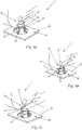
- the receiving point 7 of the alignment groove 6 lies in the direction of the axis of rotation 4 at the level of the feed channel 16, i.e. in the direction of the axis of rotation 4 at the same position as the feed channel 16 ( Fig. 5a ), wherein the mouth end 8 of the alignment groove 6 to the feed channel 16 in the direction of the axis of rotation 4 to the second boundary side 18 is laterally offset.
- Both the receiving point 7 of the alignment groove 6 and its mouth end 8 lie in the direction of the axis of rotation 4 at the level of the support area 22.
- the first boundary side 17 is adjacent to the receiving point 7 and the second boundary side 18 is adjacent to the mouth end 8 of the alignment groove 6 arranged.
- the alignment groove 6 has a local distance a from the feed channel 16 measured in the direction of the axis of rotation 4 ( Fig. 5d ), which increases continuously from the receiving point 7 to the mouth end 8 of the alignment groove 6 against the direction of rotation 5 of the shaft 3.
- the alignment groove 6 extends continuously from its receiving point 7 to its mouth end 8 both in the direction of the axis of rotation 4 and in the circumferential direction or in the direction of rotation 5. Accordingly, the alignment groove 6 does not have a section that runs only parallel to the axis of rotation 4.
- the alignment groove 6 has an arcuate course. However, differently shaped courses of the alignment groove 6 can also be expedient.
- the alignment groove 6 is delimited on the circumferential side 21 of the shaft 3 by two groove edges 36, 37.
- the first groove edge 36 is arranged near the first boundary side 17 and the second groove edge 37 is arranged near the second boundary side 18.
- the first groove edge 36 is arranged downstream of the second groove edge 37 in the direction of rotation 5 of the shaft 3.
- the alignment groove 6 has a groove width b which corresponds to the distance between the groove edges 36, 37 measured in the direction of the axis of rotation 4.
- the alignment groove 6 has a groove depth c ( Fig. 5c ), which corresponds to the maximum distance between the groove bottom 38 and the peripheral side 21 of the shaft 3 measured radially to the axis of rotation 4.
- both the groove width b and the groove depth c increase from the receiving point 7 to the mouth end 8 against the direction of rotation 5 of the shaft 3.
- the groove width b is greater than the groove depth c on each circumferential section.
- the alignment groove 6 has an effective depth 9 measured in the radial direction to the axis of rotation 4 ( Fig. 5b ), which also increases from the receiving point 7 to the mouth end 8 against the direction of rotation 5 of the shaft 3.
- the effective depth 9 of the alignment groove 6 results from the groove width c and the groove depth b and corresponds to a distance measured in the radial direction of the axis of rotation 4 by which the tablet 2 lowers into the alignment groove 6 starting from the peripheral side 21 of the shaft 3. The deeper the tablet 2 sinks into the alignment groove 6, the better the tablet 2 is guided in the alignment groove 2.
- the alignment groove 6 opens with its mouth end 8 into a receiving pocket 12.
- the receiving pocket 12 has a flat pocket bottom 13 which lies on a plane which is spanned by a secant of the cylindrical shaft circumference and by a parallel to the axis of rotation 4. Outside of the adjacent mouth end 8, the receiving pocket 12 is delimited circumferentially by high sides 40, which specify a width d of the receiving pocket 12 measured in the direction of the axis of rotation 4.
- the width d of the receiving pocket 12 is slightly larger than the diameter f of the tablet 2. This ensures that the tablet 2 slides into the receiving pocket 12 without the tablet 2 jamming or catching on the high sides 40 of the receiving pocket 12.
- the receiving pocket 12 extends starting from the mouth end 8 of the alignment groove 6 to a pocket end 39, which serves as a defined stop for the tablet 2.
- the pocket end 39 is partially rounded on the high sides 40 running perpendicular to the pocket bottom 13 in order to enable the tablet 2 to rest flatly by means of its peripheral side 41.
- the receiving pocket 12 has a depth e at its pocket end 39, which corresponds to the distance between the pocket bottom 13 and the peripheral side 21 of the shaft 3 measured in the radial direction to the axis of rotation 4.
- the depth e of the receiving pocket 12 at its pocket end 39 corresponds approximately to the thickness j of the tablet 2.
- the alignment device 1 has a vacuum delivery unit, not shown, which is used to provide vacuum.
- the shaft 3 is provided with a vacuum bore 25 extending in the direction of the axis of rotation 4, which is connected to the vacuum delivery unit in a flow and pressure transmitting manner.
- a suction bore 24 is formed in the receiving pocket 12, which extends from the pocket bottom 13 to the vacuum bore 25 of the shaft 3, and which is connected to the vacuum bore by means of a pressure channel, not shown. Accordingly, the suction bore 24 is connected via the vacuum bore 25 to the vacuum delivery unit in a flow-transmitting and pressure-transmitting manner, as a result of which a vacuum for holding the tablet 2 can be provided in the receiving pocket 12 on the suction bore 24.
- the flat pocket bottom 13 favors the flat support of the tablet 2 on the opening of the suction bore 24, so that the tablet 2 closes the suction bore 24 and a sufficiently high negative pressure can be formed to hold the tablet 2.
- the flat pocket bottom 13 is optionally provided in the area of the suction bore 24 with a small suction pocket 31 which surrounds the suction bore 24. Vacuum is applied to the tablet 2 over the comparatively large effective area of the pocket in order to be able to hold it effectively and thus to effectively counteract the radial force when the shaft 3 is rotated.
- the cross section of the suction bore 24 can be kept small, as a result of which only a small volume flow of air has to be sucked in to provide the negative pressure.
- the support unit 15 and the shaft 3 are arranged at a distance i from one another.
- the distance i is so large that the shaft 3 and the support unit 15 do not make contact.
- the distance i is less than the thickness j of a tablet 2, so that the tablet 2 in the guideway 10 ( Fig. 1 ) remains without falling through between shaft 3 and support unit 15.
- FIG. 1 is the tablet 2 with one of its bottom sides 42 leaning against the support unit 15. The bottom side 42 runs approximately parallel to the support wall 19 of the support unit 15.
- the tablet 2 lies with its peripheral side 41 on the peripheral side 21 of the shaft 3.
- the tablet 2 lies with its bottom side 42 on the shaft 3 and is supported with its peripheral side 41 on the support wall 19.
- Fig. 4b The tablet 2 only contacts with its peripheral side 41 the peripheral side 21 of the shaft 3 and the support wall 19 of the support unit 15.
- the tablet 2 lies in all positions in the support area 22 of the shaft 2 at the level of the feed channel 16.
- the shaft 3 is initially positioned when the tablet 2 is fed onto the shaft 3 in such a way that the alignment groove 6 is completely or at least partially covered by the support unit 15. After feeding the tablet 2, the shaft 3 rotates in the direction of rotation 5 of the shaft 3, as in FIG Fig. 3 shown. With the rotation of the shaft 3, the alignment groove 6 rotates continuously from its hidden position under the support unit 15.
- FIG. 5a shows the shaft 3 in a position in which the alignment groove 6 is at least partially turned freely.
- the receiving point 7 is located above the mouth end 8 of the alignment groove 6, so that the alignment groove 6 runs continuously from the receiving point 7 to its mouth end 8 downward in the direction of gravity g.
- the tablet 2 slides under the action of gravity g along the circumferential side 21 of the shaft 3 into the receiving point 7 of the alignment groove 6 and is essentially held on the circumferential side 41 in the alignment groove 6 at the first receiving edge 36.
- the tablet 2 slides and / or rolls downward by gravity g along the first groove edge 36 until the tablet 2 strikes the support wall 19.
- the tablet 2 can be supported with its peripheral side 41 on the projection side 35 and on the support wall 19 and thereby be moved to tip over when the shaft 3 rotates, provided the alignment projection 20 is designed accordingly.
- the first circumferential groove 6 would then initiate the tipping over of the tablet 2, while the subsequent circumferential groove, not shown here, ensures the further transport of the tablet 2.
- the alignment projection 20 of the support unit 15 in the preferred exemplary embodiment shown has a distance h from the circumferential side 21 of the shaft 3 measured in the direction of gravity g ( Fig.
- the tablet 2 is larger than the diameter f of the tablet 2, the tablet 2 is able to slide under the alignment projection 20 without contact with the projection side 35.
- the alignment projection 20 therefore plays no role here for the alignment process.
- the tablet stands intrinsically stable with its peripheral side on the peripheral side of the cylindrical shaft 3.
- the circumferential groove 6 now passes under the tablet 2, which then only comes to rest on the leading groove edge 37.
- the balance of the tablet 2 is disturbed so that it tips over.
- Fig. 5a And then to Fig. 5b Aligns the tablet 2 with its bottom side 42 approximately parallel to the axis of rotation 4 and lies in the alignment groove 6.
- the tablet 2 sinks increasingly with the progressive rotation of the shaft 3 in the alignment groove 6.
- the alignment groove 6 is further released by the support unit 15 with continuous rotation of the shaft 3.
- the distance a measured in the direction of the axis of rotation 4 between the alignment groove 6 and the feed channel 16, which increases counter to the direction of rotation 5 causes the tablet 2 to be conveyed in the direction of the axis of rotation 4 with the rotation of the shaft 3.
- the tablet 2 slides and / or rolls from the receiving point 7 to the mouth end 8 of the alignment groove.
- the tablet 2 slides with rotation of the shaft 3 from the mouth end 8 of the alignment groove 6 into the receiving pocket 12.
- the tablet 2 is preferably flat against the high sides 40, whereby the tablet 2 is in a defined orientation .
- it is held by means of a vacuum.
- vacuum on the suction bore 24 and on the above already in connection with Fig. 2 mentioned optional suction bag 31 switched on, whereby the tablet 2 is fixed by means of the negative pressure in the receiving pocket 12.
- the vacuum is provided by the vacuum delivery unit, which is connected via the vacuum bore 25 of the shaft 3 to the suction bore 24 in a flow and pressure transmitting manner.
- the vacuum can be switched on and off as required via the vacuum delivery unit.
- a permanent supply of vacuum can also be useful.
- Fig. 5d shows, by fixing the tablet 2 by means of a vacuum, the shaft 3 can be rotated further into any transfer position without the tablet 2 falling from the shaft 3 due to the force of gravity g.
- a gripping process of a gripping unit 26 of the alignment device 1 is shown in a transfer position 30.
- the gripping unit 26 is arranged on the circumference of the shaft 3.
- the gripping unit 26 is arranged below the shaft 3, but other arrangements of the gripping unit 26 can also be expedient.
- the gripping unit 26 comprises three gripping arms 27.
- a different number of gripping arms 27 can also be expedient.
- the number of gripping arms 27 can be adapted to the diameter f of the tablet 2.
- the gripping arms 27 are arranged in a circle on a base plate 28 at an equal angular distance.
- the gripping arms 27 are resiliently arranged on the base plate 28 in the exemplary embodiment.
- the circular diameter formed by the gripping arms 27 is somewhat smaller than the diameter f of the tablet 2. It can also be expedient to provide actively moving gripping arms. Using a mechanism, for example, they can reduce and expand the circle diameter they have formed, thus actively grasping and releasing the tablet. So that the tablet 2 can be picked up by the gripping arms 27, 27 recesses 14 are provided in the receiving pocket 12 corresponding to the number of gripping arms. The gripping arms 27 can thus dip into the recesses 14 and grip the tablet 2.
- the shaft 3 moves into the transfer position 30, as in FIG Fig. 6a shown.
- the tablet 2 is located directly opposite the gripping unit 26.
- the gripping unit 26 travels in the direction of the shaft 3 and dips into the recesses 14 with its gripping arms 27 the receiving pocket 12 a. Since the diameter formed by the gripping arms 27 is smaller than the diameter f of the tablet 2, the gripping arms 27 contact the tablet 2 at their ends 29 Fig. 6b shown, the gripping arms 27 grasp the ends 29 of the peripheral side 41 of the tablet 2 and are slightly bent.
- the shaft 3 can also have a plurality of alignment grooves 6 arranged one behind the other in the circumferential direction of the shaft 3.
- the number of aligned tablets 2 per revolution of the shaft 3 can thus be increased.
- the number of aligning devices 1 can be adapted, thereby ensuring a corresponding supply of aligned tablets.
Landscapes
- Engineering & Computer Science (AREA)
- Mechanical Engineering (AREA)
- Health & Medical Sciences (AREA)
- Life Sciences & Earth Sciences (AREA)
- Animal Behavior & Ethology (AREA)
- General Health & Medical Sciences (AREA)
- Public Health (AREA)
- Veterinary Medicine (AREA)
- Pharmacology & Pharmacy (AREA)
- Basic Packing Technique (AREA)
- Feeding Of Articles To Conveyors (AREA)
- Medical Preparation Storing Or Oral Administration Devices (AREA)
Priority Applications (4)
| Application Number | Priority Date | Filing Date | Title |
|---|---|---|---|
| EP18191193.4A EP3617080A1 (fr) | 2018-08-28 | 2018-08-28 | Dispositif d'alignement destiné à aligner des comprimés, procédé d'alignement de comprimés |
| CA3051974A CA3051974A1 (fr) | 2018-08-28 | 2019-08-14 | Dispositif d`alignement pour aligner des comprimes, procede d`alignement de comprimes |
| US16/548,484 US20200069527A1 (en) | 2018-08-28 | 2019-08-22 | Alignment apparatus for aligning tablets, method for aligning tablets |
| CN201910802472.1A CN110861805A (zh) | 2018-08-28 | 2019-08-28 | 用于定向药片的定向设备、用于定向药片的方法 |
Applications Claiming Priority (1)
| Application Number | Priority Date | Filing Date | Title |
|---|---|---|---|
| EP18191193.4A EP3617080A1 (fr) | 2018-08-28 | 2018-08-28 | Dispositif d'alignement destiné à aligner des comprimés, procédé d'alignement de comprimés |
Publications (1)
| Publication Number | Publication Date |
|---|---|
| EP3617080A1 true EP3617080A1 (fr) | 2020-03-04 |
Family
ID=63442480
Family Applications (1)
| Application Number | Title | Priority Date | Filing Date |
|---|---|---|---|
| EP18191193.4A Withdrawn EP3617080A1 (fr) | 2018-08-28 | 2018-08-28 | Dispositif d'alignement destiné à aligner des comprimés, procédé d'alignement de comprimés |
Country Status (4)
| Country | Link |
|---|---|
| US (1) | US20200069527A1 (fr) |
| EP (1) | EP3617080A1 (fr) |
| CN (1) | CN110861805A (fr) |
| CA (1) | CA3051974A1 (fr) |
Families Citing this family (2)
| Publication number | Priority date | Publication date | Assignee | Title |
|---|---|---|---|---|
| CN112206158A (zh) * | 2020-08-31 | 2021-01-12 | 武汉城市职业学院 | 一种服药设备 |
| CN117297976A (zh) * | 2023-11-07 | 2023-12-29 | 天津果实科技有限公司 | 一种智能自动给药装置 |
Citations (3)
| Publication number | Priority date | Publication date | Assignee | Title |
|---|---|---|---|---|
| EP1391386A2 (fr) * | 2002-08-21 | 2004-02-25 | Aylward Enterprises, Inc. | Procédé et appareil pour alimenter un récipient avec des pilules |
| GB2521431A (en) * | 2013-12-19 | 2015-06-24 | Techincal Engineering And Tooling Services Ltd | Spiral Tube |
| EP2910478A1 (fr) * | 2014-02-22 | 2015-08-26 | Harro Höfliger Verpackungsmaschinen GmbH | Dispositif de dosage pour comprimés et procédé de dosage de comprimés |
-
2018
- 2018-08-28 EP EP18191193.4A patent/EP3617080A1/fr not_active Withdrawn
-
2019
- 2019-08-14 CA CA3051974A patent/CA3051974A1/fr not_active Abandoned
- 2019-08-22 US US16/548,484 patent/US20200069527A1/en not_active Abandoned
- 2019-08-28 CN CN201910802472.1A patent/CN110861805A/zh active Pending
Patent Citations (3)
| Publication number | Priority date | Publication date | Assignee | Title |
|---|---|---|---|---|
| EP1391386A2 (fr) * | 2002-08-21 | 2004-02-25 | Aylward Enterprises, Inc. | Procédé et appareil pour alimenter un récipient avec des pilules |
| GB2521431A (en) * | 2013-12-19 | 2015-06-24 | Techincal Engineering And Tooling Services Ltd | Spiral Tube |
| EP2910478A1 (fr) * | 2014-02-22 | 2015-08-26 | Harro Höfliger Verpackungsmaschinen GmbH | Dispositif de dosage pour comprimés et procédé de dosage de comprimés |
Also Published As
| Publication number | Publication date |
|---|---|
| CA3051974A1 (fr) | 2020-02-28 |
| US20200069527A1 (en) | 2020-03-05 |
| CN110861805A (zh) | 2020-03-06 |
Similar Documents
| Publication | Publication Date | Title |
|---|---|---|
| DE2403619C2 (de) | Vorrichtung zum kontinuierlichen Ausrichten zweiteiliger Hartkapseln | |
| DE69400833T2 (de) | Förderer für feste Gegenstände | |
| DE69628589T2 (de) | Ladvorrichtung zum zuführen von stapeln von dokumenten | |
| EP0312490B1 (fr) | Procédé et dispositif pour former et transporter des groupes de produits alimentaires plats empilables, en particulier des biscuits | |
| DE2605775B2 (de) | Vorrichtung zur Obergabe von Ampullen o.dgl | |
| DE1627733A1 (de) | Werkstuecktransportmechanismus fuer Montagemaschinen od.dgl. | |
| EP2228331B1 (fr) | Dispositif et procédé de prise en charge et de traitement d'objets plats flexibles | |
| DE1782864A1 (de) | Vorrichtung zum wenden von in einer reihe kontinuierlich angelieferten zigaretten | |
| DE102004024155B4 (de) | Vorrichtung zum Übergeben von Packungen | |
| EP2865618A1 (fr) | Dispositif pour transférer des piles d' emballages blister | |
| DE2401340B2 (de) | Einwickelvorrichtung in einer Münzverpackungsmaschine | |
| EP0987179B1 (fr) | Procédé et installation pour transférer des emballages à une station d'empilage | |
| DE2747799C2 (fr) | ||
| EP3617080A1 (fr) | Dispositif d'alignement destiné à aligner des comprimés, procédé d'alignement de comprimés | |
| DE60221268T2 (de) | Übergabevorrichtung für zylindrische stapel von auf einer kante angeordneten produkten | |
| EP2297014B1 (fr) | Dispositif d'insertion et procédé d'insertion | |
| AT522525B1 (de) | Pipettenspitzentrennsystem | |
| DE60310904T2 (de) | Einwickelmaschine | |
| CH671389A5 (fr) | ||
| WO2002024556A1 (fr) | Procede et dispositif d'apport d'objets reguliers a une station de travail | |
| DE2150954C3 (de) | Vorrichtung an einer Verpackungsmaschine zur gleichförmigen taktgerechten Belieferung eines schnellaufenden Abführförderers | |
| CH715069B1 (de) | Fördereinrichtung und Verfahren zum Fördern von Tampon-Applikatoren. | |
| DE102017104098A1 (de) | Kapselverpackungssystem | |
| EP3257762A1 (fr) | Dispositif de formation de piles de plaquettes thermoformees comprenant des elements de fixation souples | |
| EP2812266B1 (fr) | Dispositif et système de transfert et procédé correspondant |
Legal Events
| Date | Code | Title | Description |
|---|---|---|---|
| PUAI | Public reference made under article 153(3) epc to a published international application that has entered the european phase |
Free format text: ORIGINAL CODE: 0009012 |
|
| AK | Designated contracting states |
Kind code of ref document: A1 Designated state(s): AL AT BE BG CH CY CZ DE DK EE ES FI FR GB GR HR HU IE IS IT LI LT LU LV MC MK MT NL NO PL PT RO RS SE SI SK SM TR |
|
| AX | Request for extension of the european patent |
Extension state: BA ME |
|
| STAA | Information on the status of an ep patent application or granted ep patent |
Free format text: STATUS: THE APPLICATION IS DEEMED TO BE WITHDRAWN |
|
| 18D | Application deemed to be withdrawn |
Effective date: 20200905 |