EP3617103A1 - Führungsvorrichtung für schüttgutförderer - Google Patents
Führungsvorrichtung für schüttgutförderer Download PDFInfo
- Publication number
- EP3617103A1 EP3617103A1 EP19183398.7A EP19183398A EP3617103A1 EP 3617103 A1 EP3617103 A1 EP 3617103A1 EP 19183398 A EP19183398 A EP 19183398A EP 3617103 A1 EP3617103 A1 EP 3617103A1
- Authority
- EP
- European Patent Office
- Prior art keywords
- pin
- guiding device
- positioning element
- channel
- conveyor
- Prior art date
- Legal status (The legal status is an assumption and is not a legal conclusion. Google has not performed a legal analysis and makes no representation as to the accuracy of the status listed.)
- Granted
Links
Images





Classifications
-
- B—PERFORMING OPERATIONS; TRANSPORTING
- B65—CONVEYING; PACKING; STORING; HANDLING THIN OR FILAMENTARY MATERIAL
- B65G—TRANSPORT OR STORAGE DEVICES, e.g. CONVEYORS FOR LOADING OR TIPPING, SHOP CONVEYOR SYSTEMS OR PNEUMATIC TUBE CONVEYORS
- B65G21/00—Supporting or protective framework or housings for endless load-carriers or traction elements of belt or chain conveyors
- B65G21/20—Means incorporated in, or attached to, framework or housings for guiding load-carriers, traction elements or loads supported on moving surfaces
- B65G21/2045—Mechanical means for guiding or retaining the load on the load-carrying surface
- B65G21/2054—Mechanical means for guiding or retaining the load on the load-carrying surface comprising elements movable in the direction of load-transport
-
- B—PERFORMING OPERATIONS; TRANSPORTING
- B65—CONVEYING; PACKING; STORING; HANDLING THIN OR FILAMENTARY MATERIAL
- B65G—TRANSPORT OR STORAGE DEVICES, e.g. CONVEYORS FOR LOADING OR TIPPING, SHOP CONVEYOR SYSTEMS OR PNEUMATIC TUBE CONVEYORS
- B65G39/00—Rollers, e.g. drive rollers, or arrangements thereof incorporated in roller-ways or other types of mechanical conveyors
- B65G39/10—Arrangements of rollers
- B65G39/12—Arrangements of rollers mounted on framework
- B65G39/18—Arrangements of rollers mounted on framework for guiding loads
Definitions
- the present invention generally relates to bulk goods conveyors and, more specifically, to a guiding device for a bulk goods conveyor.
- a bulk goods conveyor defines a movement plane for general goods to be transported.
- a conveyor is generally a closed ring or endless ring one and possibly comprises, for example, a belt, a plurality of interconnected rollers, or a chain with articulated links.
- the guiding devices In bulk goods conveyors, the use is also known of guiding devices that provide containment and/or conveyance of the goods being transported.
- the guiding devices define respective sliding surfaces which are substantially orthogonal to the plane wherein the conveyor moves, said sliding surfaces developing along the desired direction of movement of the goods being transported.
- the guiding devices develop along a direction which is either a straight line, an open broken line, or a curve, depending on the actual needs.
- lateral guides or sideboards feature one sliding surface
- central or partition guides have two sliding surfaces, opposite and substantially parallel to each other.
- Central guides are positioned, for example, at the forks of the conveyor, i.e. wherever a stream of objects is to be split into two separate streams.
- the sliding surfaces of lateral and central guides are typically implemented by a plurality of rolling bodies mounted idle on axles that are parallel to each other.
- the rolling bodies comprise, for example, cylindrical rollers, spheres, or rotated ellipsoids.
- the use of lateral and/or central guides with sliding surfaces defined by idle rolling bodies reduces friction phenomena and makes it possible a more regular forward movement of the stream of goods, while limiting the so-called "bridging" risks.
- each guiding device includes a support shell.
- the support shell is provided with housings suitable for receiving roller-holder racks.
- Such support shell is also provided with coupling means for securing the guiding device to the conveyor frame.
- the guiding devices provided with rolling bodies are in any case formed of a high number of component parts separate from each other.
- these guiding devices also include a plurality of rolling bodies, aligned along various axes parallel to each other, a further plurality of pins, wherein each pin makes-up the axis of rotation of a predefined number of such rolling bodies, as well as a plurality of spacing elements which are usually interposed between any two adjacent rolling bodies, driven into rotation about one and the same pin, and/or between any rolling body mounted on a given pin and one of the roller-holder racks.
- Such high number of component parts entails a need for performing numerous machining processes to obtain all component parts necessary for the operation of the guiding device. Such high number of component parts also makes the operations necessary for assembling the guiding device difficult to perform.
- An object of the present invention is thus to provide a guiding device for a bulk goods conveyor that is capable of solving the above-mentioned drawbacks of the known prior art in an extremely simple, cost-effective, and particularly functional manner.
- an object of the present invention is to provide a guiding device for a bulk goods conveyor that includes a lower number of functional component parts as compared to similar guiding devices according to the known prior art.
- Another object of the present invention is to provide a guiding device for a bulk goods conveyor that makes it simpler to manufacture and assemble a guiding device itself as compared to similar guiding devices according to the known prior art.
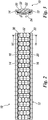
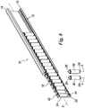
- a preferred embodiment of the guiding device for a bulk goods conveyor according to the present invention is illustrated with specific reference to figures 1 to 3 .
- the guiding device is identified as a whole by the reference numeral 10.
- the guiding device 10 is of a type comprising a support structure 12 which develops along a predefined axis X, typically parallel to the axis of development and movement of the conveyor which the guiding device 10 can be coupled with.
- the axis of development X of the support structure 12 is either a straight line, an open broken line, or a curve, depending on the shape of the conveyor which the guiding device 10 can be coupled with.
- the support structure 12 is preferably formed of an aluminum profile having a substantially constant cross section, irrespective of its shape and longitudinal development.
- the support structure 12 comprises at least one first channel 14 and at least one second channel 16 substantially opposite to each other, spaced away from each other and oriented along their respective axes substantially parallel to the axis of development X of the support structure 12 itself.
- the first channel 14 and the second channel 16 of the support structure 12 are consequently substantially equidistant.
- the support structure 12 also includes coupling means 24 for coupling with a fixed structure of the conveyor.
- the coupling means 24 are preferably obtained on a surface of the support structure 12 that is opposite to the surface whereon the first channel 14 and the second channel 16 are obtained.
- the coupling means 24 might comprise a third channel designed to be connected to a corresponding fixed structure of the conveyor via a sliding coupling.
- the guiding device 10 also comprises at least one first positioning element 18, slidably inserted into the first channel 14 of the support structure 12, and at least one second positioning element 20, slidably inserted into the second channel 16 of said support structure 12.
- first positioning element 18 and the second positioning element 20 are consequently also substantially opposite to each other, spaced away from each other, and oriented along their respective axes substantially parallel to the axis of development X of the support structure 12.
- the first positioning element 18 and the second positioning element 20 are preferably made from a polymeric material. Even more preferably, the first positioning element 18 and the second positioning element 20 are made from a polyoxymethylene (POM)-based acetal resin.
- POM polyoxymethylene
- acetal resins are very rigid plastic materials that feature good mechanical strengths, hardness, and dimensional stability characteristics, thanks to the fact that they absorb little humidity. Therefore, acetal resins are particularly suitable for manufacturing precision mechanical parts.
- a plurality of pins 22 are rotatably interposed between the first positioning element 18 and the second positioning element 20.
- Each pin 22 supports one or several rolling bodies 30, 32, 34, 36, 38, 40 designed to define, as a whole, a sliding surface for the goods being transported on the conveyor which the guiding device 10 is coupled with.
- at least one of the rolling bodies 30, 34, 36, 38, 40 is supported by a respective pin 22 integrally formed with such pin 22, so as to reduce the number of functional component parts of the guiding device 10 as compared to similar guiding devices according to the known prior art.
- the pins 22 and their respective rolling bodies 30, 32, 34, 36, 38, 40 are also preferably made from a polymeric material. Even more preferably, the pins 22 and their respective rolling bodies 30, 32, 34, 36, 38, 40 are made from the same polyoxymethylene (POM)-based acetal resin that the first positioning element 18 and the second positioning element 20 are made from.
- POM polyoxymethylene
- the pins 22 are oriented along their respective axes Y parallel to each other and substantially perpendicular to the axis of development X of the support structure 12. Therefore, the rotation of the pins 22 and their respective rolling bodies 30, 32, 34, 36, 38, 40 with respect to these axes Y helps in conveying the goods placed on the conveyor, when in contact with such rolling bodies 30, 32, 34, 36, 38, 40, in the direction of movement of such conveyor.
- Each pin 22 is provided with a first end portion 26 and a second end portion 28 opposite to each other, designed for being snap-fitted within corresponding seats 42, 44 obtained on the first positioning element 18 and on the second positioning element 20 respectively.
- the pins 22 being snap-mounted on their respective position elements 18 and 20 helps in simplifying the manufacturing steps of the guiding device 10.
- the first positioning element 18 and the second positioning element 20 can be reciprocally joined by way of at least one connecting surface 54 integrally formed with such first positioning element 18 and with such second positioning element 20.
- the first positioning element 18, the second positioning element 20, and their respective connecting surface 54 being preferably made from one polymeric material, can be easily manufactured in one molding step.
- the connecting surface 54 is obviously configured in such a way as not to interfere with the rotation of the pins 22 and of the rolling bodies 30, 32, 34, 36, 38, 40.
- the connecting surface 54 can thus be implemented in the form of a plurality of small bridges substantially oriented according to the axes Y of the pins 22 and interposed between the seats 42, 44 for snap-mounting such pins 22.
- the connecting surface 54 can be implemented in the form of a continuous wall, interposed between the support structure 12 and the pins 22 along with their respective rolling bodies 30, 32, 34, 36, 38, 40.
- each pin 22 is integrally formed with a rolling body 30 comprised of at least one spacing element having a substantially cylindrical shape, located at one of the two end portions 26 or 28 of such pin 22. Then at least one further roll-shaped rolling body 32, designed to rotate around the axis Y of such pin 22, is fitted onto the remaining part of the surface of the pin 22.
- the rolling body 32 can be implemented in the form of two or several spheres joined to each other, each having a diameter greater than the diameter of the spacing element 30 and provided with a through hole 46 within which a respective pin 22 is introduced.
- the spacing element 30 is consequently interposed between the rolling body 32 and either end portion 26 or 28 of the pin 22 in an assembled configuration of the guiding device 10.
- each pin 22 is integrally formed both with a first rolling body 30, comprised of at least one substantially cylindrically shaped spacing element at either end portion 26 or 28 of such pin 22, and with a second rolling body 34, implemented in the form of two or several spheres joined to each other, having a diameter greater than the diameter of the spacing element 30 and placed side by side with such spacing element 30 along the axis Y of its respective pin 22.
- each pin 22 is comprised of a one-piece element which also includes its respective rolling bodies 30 and 34.
- Figure 7 shows a variant of the second embodiment of the guiding device 10.
- the pins 22 and their respective rolling bodies 30 and 34, integrally formed with such pins 22, are substantially equal to those of the second embodiment of the guiding device 10 as described above.
- the distance between the axes Y of pairs of contiguous pins 22, as measured along the axis of development X of the support structure 12, is shorter in this variant.
- the pins 22 are particularly close to each other in this variant, so that the surfaces of the rolling bodies 34 of pins 22 contiguous to each other can partially compenetrate.
- each pin 22 is integrally formed with one rolling body 36 which consists of a straight circular cylinder, which axially extends between the two end portions 26 and 28 of its respective pin 22.
- the cylindrical rolling body 36 extends almost along the axial length of its respective pin 22, but at the two end portions 26 and 28.
- each pin 22 is integrally formed with at least two rolling bodies 38 and 40 formed of respective straight circular cylinders.
- An intermediate section of its respective pin 22 is interposed between the two rolling bodies 38 and 40 and is designed for being snap-fitted within a corresponding seat 52 obtained on a third positioning element 50 of the support structure 12, interposed between the first positioning element 18 and the second positioning element 20 and substantially parallel to such first positioning element 18 and second positioning element 20.
Landscapes
- Engineering & Computer Science (AREA)
- Mechanical Engineering (AREA)
- Framework For Endless Conveyors (AREA)
- Branching, Merging, And Special Transfer Between Conveyors (AREA)
Applications Claiming Priority (1)
| Application Number | Priority Date | Filing Date | Title |
|---|---|---|---|
| IT102018000008205A IT201800008205A1 (it) | 2018-08-28 | 2018-08-28 | Dispositivo di guida per trasportatori di oggetti in massa |
Publications (2)
| Publication Number | Publication Date |
|---|---|
| EP3617103A1 true EP3617103A1 (de) | 2020-03-04 |
| EP3617103B1 EP3617103B1 (de) | 2021-05-05 |
Family
ID=64316751
Family Applications (1)
| Application Number | Title | Priority Date | Filing Date |
|---|---|---|---|
| EP19183398.7A Active EP3617103B1 (de) | 2018-08-28 | 2019-06-28 | Führungsvorrichtung für schüttgutförderer |
Country Status (3)
| Country | Link |
|---|---|
| EP (1) | EP3617103B1 (de) |
| ES (1) | ES2881724T3 (de) |
| IT (1) | IT201800008205A1 (de) |
Citations (11)
| Publication number | Priority date | Publication date | Assignee | Title |
|---|---|---|---|---|
| EP0787666A2 (de) | 1996-02-01 | 1997-08-06 | Marbett S.p.A. | Sektionsrolle-Einheit für Förderlinien |
| EP0894745A1 (de) | 1997-08-01 | 1999-02-03 | System Plast S.n.c. di Marsetti & C. Stampaggio Tecnopolimeri | Sektionale Rolleneinheit für Förderlinien |
| EP0931737A1 (de) | 1998-01-22 | 1999-07-28 | Rexnord Marbett S.p.A. | Vorrichtung mit Leitrollen für eine Leitwand für Stückgutförderer |
| US5957261A (en) | 1995-10-31 | 1999-09-28 | Canon Kabushiki Kaisha | Roller and method of manufacturing the roller |
| US20020017067A1 (en) * | 2000-08-09 | 2002-02-14 | System Plast S.P.A. | Wall element incorporating idle rollers |
| WO2002036462A2 (en) * | 2000-11-03 | 2002-05-10 | Solus Industrial Innovations, Llc | Bendable rolling conveyor guide |
| EP1340698A1 (de) | 2002-02-27 | 2003-09-03 | Rexnord Marbett S.p.A. | Führung für Stückgutförderer |
| EP1723057A1 (de) | 2004-02-27 | 2006-11-22 | LEDINGHAM, Stuart J. | Biegbare rollfördereinrichtungsführung |
| EP1905708A2 (de) | 2006-09-26 | 2008-04-02 | Rexnord Marbett s.r.l. | Führungsanordnung für Förderband für Artikel mit erhöhter Biegefestigkeit |
| DE202012003039U1 (de) * | 2011-03-25 | 2012-08-30 | Rexnord Marbett S.R.L. | Zentrale Führung für eine Artikel-Fördervorrichtung |
| EP3070032A1 (de) * | 2015-03-18 | 2016-09-21 | Movex S.p.A. | Biegbare seitenführungseinrichtung |
-
2018
- 2018-08-28 IT IT102018000008205A patent/IT201800008205A1/it unknown
-
2019
- 2019-06-28 EP EP19183398.7A patent/EP3617103B1/de active Active
- 2019-06-28 ES ES19183398T patent/ES2881724T3/es active Active
Patent Citations (11)
| Publication number | Priority date | Publication date | Assignee | Title |
|---|---|---|---|---|
| US5957261A (en) | 1995-10-31 | 1999-09-28 | Canon Kabushiki Kaisha | Roller and method of manufacturing the roller |
| EP0787666A2 (de) | 1996-02-01 | 1997-08-06 | Marbett S.p.A. | Sektionsrolle-Einheit für Förderlinien |
| EP0894745A1 (de) | 1997-08-01 | 1999-02-03 | System Plast S.n.c. di Marsetti & C. Stampaggio Tecnopolimeri | Sektionale Rolleneinheit für Förderlinien |
| EP0931737A1 (de) | 1998-01-22 | 1999-07-28 | Rexnord Marbett S.p.A. | Vorrichtung mit Leitrollen für eine Leitwand für Stückgutförderer |
| US20020017067A1 (en) * | 2000-08-09 | 2002-02-14 | System Plast S.P.A. | Wall element incorporating idle rollers |
| WO2002036462A2 (en) * | 2000-11-03 | 2002-05-10 | Solus Industrial Innovations, Llc | Bendable rolling conveyor guide |
| EP1340698A1 (de) | 2002-02-27 | 2003-09-03 | Rexnord Marbett S.p.A. | Führung für Stückgutförderer |
| EP1723057A1 (de) | 2004-02-27 | 2006-11-22 | LEDINGHAM, Stuart J. | Biegbare rollfördereinrichtungsführung |
| EP1905708A2 (de) | 2006-09-26 | 2008-04-02 | Rexnord Marbett s.r.l. | Führungsanordnung für Förderband für Artikel mit erhöhter Biegefestigkeit |
| DE202012003039U1 (de) * | 2011-03-25 | 2012-08-30 | Rexnord Marbett S.R.L. | Zentrale Führung für eine Artikel-Fördervorrichtung |
| EP3070032A1 (de) * | 2015-03-18 | 2016-09-21 | Movex S.p.A. | Biegbare seitenführungseinrichtung |
Also Published As
| Publication number | Publication date |
|---|---|
| ES2881724T3 (es) | 2021-11-30 |
| EP3617103B1 (de) | 2021-05-05 |
| IT201800008205A1 (it) | 2020-02-28 |
Similar Documents
| Publication | Publication Date | Title |
|---|---|---|
| US7837028B2 (en) | Radius chain modular conveyor | |
| CA1166658A (en) | Positively driven steering member for conveying apparatus | |
| KR20050113630A (ko) | 롤러 크래들을 구비한 모듈형 컨베이어 조립체 | |
| US5655642A (en) | Idler roll for use in belt conveyor systems | |
| ES2683717T3 (es) | Dispositivo transportador para transportar objetos | |
| US3923150A (en) | Device for conveying objects | |
| AU2010206045A1 (en) | A support device for a conveyor installation and method for operation of a conveyor installation | |
| KR20130139216A (ko) | 내마모성 적층형 롤러를 구비한 컨베이어 벨트 | |
| EP3617103B1 (de) | Führungsvorrichtung für schüttgutförderer | |
| KR20140139558A (ko) | 컨베이어 체인 링크, 컨베이어 체인, 컨베이어 체인을 위한 구동 휠 및 이러한 구동 휠을 포함하는 시스템 | |
| JP5743361B1 (ja) | 仕分装置およびスラット | |
| CN103380068B (zh) | 伸缩型辊式传输器和框架 | |
| US11078023B2 (en) | Guiding device for bulk goods conveyors | |
| US8746442B2 (en) | Conveyor belt rollers with two surface materials | |
| KR101834668B1 (ko) | 이송용 팔레트 | |
| JP6004316B2 (ja) | 少なくとも1つの物体を運搬するための移載装置及び移載方法 | |
| EP3255291B1 (de) | Gleitlager | |
| CN102782346A (zh) | 轴支撑结构 | |
| JP2000344323A (ja) | フレキシブルコンベヤー | |
| CN112777192B (zh) | 搬送装置和搬送方向变更装置 | |
| JP2005247489A (ja) | 姿勢変更搬送装置 | |
| CN107735216A (zh) | 搬运链 | |
| JPH10338326A (ja) | プラスチック製コンベアベルトおよびこれを用いたコンベア装置 | |
| EP4005951A1 (de) | Modulares rollenförderbandmodul und durch mehrere solcher module gebildetes modulares förderband | |
| US3779356A (en) | Roller for roller conveyors |
Legal Events
| Date | Code | Title | Description |
|---|---|---|---|
| PUAI | Public reference made under article 153(3) epc to a published international application that has entered the european phase |
Free format text: ORIGINAL CODE: 0009012 |
|
| STAA | Information on the status of an ep patent application or granted ep patent |
Free format text: STATUS: THE APPLICATION HAS BEEN PUBLISHED |
|
| AK | Designated contracting states |
Kind code of ref document: A1 Designated state(s): AL AT BE BG CH CY CZ DE DK EE ES FI FR GB GR HR HU IE IS IT LI LT LU LV MC MK MT NL NO PL PT RO RS SE SI SK SM TR |
|
| AX | Request for extension of the european patent |
Extension state: BA ME |
|
| STAA | Information on the status of an ep patent application or granted ep patent |
Free format text: STATUS: REQUEST FOR EXAMINATION WAS MADE |
|
| RBV | Designated contracting states (corrected) |
Designated state(s): AL AT BE BG CH CY CZ DE DK EE ES FI FR GB GR HR HU IE IS IT LI LT LU LV MC MK MT NL NO PL PT RO RS SE SI SK SM TR |
|
| 17P | Request for examination filed |
Effective date: 20200309 |
|
| GRAP | Despatch of communication of intention to grant a patent |
Free format text: ORIGINAL CODE: EPIDOSNIGR1 |
|
| STAA | Information on the status of an ep patent application or granted ep patent |
Free format text: STATUS: GRANT OF PATENT IS INTENDED |
|
| RIC1 | Information provided on ipc code assigned before grant |
Ipc: B65G 21/20 20060101AFI20210111BHEP Ipc: B65G 39/18 20060101ALN20210111BHEP |
|
| INTG | Intention to grant announced |
Effective date: 20210211 |
|
| GRAS | Grant fee paid |
Free format text: ORIGINAL CODE: EPIDOSNIGR3 |
|
| GRAA | (expected) grant |
Free format text: ORIGINAL CODE: 0009210 |
|
| STAA | Information on the status of an ep patent application or granted ep patent |
Free format text: STATUS: THE PATENT HAS BEEN GRANTED |
|
| AK | Designated contracting states |
Kind code of ref document: B1 Designated state(s): AL AT BE BG CH CY CZ DE DK EE ES FI FR GB GR HR HU IE IS IT LI LT LU LV MC MK MT NL NO PL PT RO RS SE SI SK SM TR |
|
| REG | Reference to a national code |
Ref country code: GB Ref legal event code: FG4D |
|
| REG | Reference to a national code |
Ref country code: CH Ref legal event code: EP |
|
| REG | Reference to a national code |
Ref country code: AT Ref legal event code: REF Ref document number: 1389583 Country of ref document: AT Kind code of ref document: T Effective date: 20210515 |
|
| REG | Reference to a national code |
Ref country code: IE Ref legal event code: FG4D |
|
| REG | Reference to a national code |
Ref country code: DE Ref legal event code: R096 Ref document number: 602019004411 Country of ref document: DE |
|
| REG | Reference to a national code |
Ref country code: NL Ref legal event code: FP |
|
| REG | Reference to a national code |
Ref country code: LT Ref legal event code: MG9D |
|
| REG | Reference to a national code |
Ref country code: AT Ref legal event code: MK05 Ref document number: 1389583 Country of ref document: AT Kind code of ref document: T Effective date: 20210505 |
|
| PG25 | Lapsed in a contracting state [announced via postgrant information from national office to epo] |
Ref country code: HR Free format text: LAPSE BECAUSE OF FAILURE TO SUBMIT A TRANSLATION OF THE DESCRIPTION OR TO PAY THE FEE WITHIN THE PRESCRIBED TIME-LIMIT Effective date: 20210505 Ref country code: LT Free format text: LAPSE BECAUSE OF FAILURE TO SUBMIT A TRANSLATION OF THE DESCRIPTION OR TO PAY THE FEE WITHIN THE PRESCRIBED TIME-LIMIT Effective date: 20210505 Ref country code: FI Free format text: LAPSE BECAUSE OF FAILURE TO SUBMIT A TRANSLATION OF THE DESCRIPTION OR TO PAY THE FEE WITHIN THE PRESCRIBED TIME-LIMIT Effective date: 20210505 Ref country code: BG Free format text: LAPSE BECAUSE OF FAILURE TO SUBMIT A TRANSLATION OF THE DESCRIPTION OR TO PAY THE FEE WITHIN THE PRESCRIBED TIME-LIMIT Effective date: 20210805 Ref country code: AT Free format text: LAPSE BECAUSE OF FAILURE TO SUBMIT A TRANSLATION OF THE DESCRIPTION OR TO PAY THE FEE WITHIN THE PRESCRIBED TIME-LIMIT Effective date: 20210505 |
|
| PG25 | Lapsed in a contracting state [announced via postgrant information from national office to epo] |
Ref country code: LV Free format text: LAPSE BECAUSE OF FAILURE TO SUBMIT A TRANSLATION OF THE DESCRIPTION OR TO PAY THE FEE WITHIN THE PRESCRIBED TIME-LIMIT Effective date: 20210505 Ref country code: PL Free format text: LAPSE BECAUSE OF FAILURE TO SUBMIT A TRANSLATION OF THE DESCRIPTION OR TO PAY THE FEE WITHIN THE PRESCRIBED TIME-LIMIT Effective date: 20210505 Ref country code: NO Free format text: LAPSE BECAUSE OF FAILURE TO SUBMIT A TRANSLATION OF THE DESCRIPTION OR TO PAY THE FEE WITHIN THE PRESCRIBED TIME-LIMIT Effective date: 20210805 Ref country code: SE Free format text: LAPSE BECAUSE OF FAILURE TO SUBMIT A TRANSLATION OF THE DESCRIPTION OR TO PAY THE FEE WITHIN THE PRESCRIBED TIME-LIMIT Effective date: 20210505 Ref country code: PT Free format text: LAPSE BECAUSE OF FAILURE TO SUBMIT A TRANSLATION OF THE DESCRIPTION OR TO PAY THE FEE WITHIN THE PRESCRIBED TIME-LIMIT Effective date: 20210906 Ref country code: RS Free format text: LAPSE BECAUSE OF FAILURE TO SUBMIT A TRANSLATION OF THE DESCRIPTION OR TO PAY THE FEE WITHIN THE PRESCRIBED TIME-LIMIT Effective date: 20210505 Ref country code: GR Free format text: LAPSE BECAUSE OF FAILURE TO SUBMIT A TRANSLATION OF THE DESCRIPTION OR TO PAY THE FEE WITHIN THE PRESCRIBED TIME-LIMIT Effective date: 20210806 Ref country code: IS Free format text: LAPSE BECAUSE OF FAILURE TO SUBMIT A TRANSLATION OF THE DESCRIPTION OR TO PAY THE FEE WITHIN THE PRESCRIBED TIME-LIMIT Effective date: 20210905 |
|
| REG | Reference to a national code |
Ref country code: ES Ref legal event code: FG2A Ref document number: 2881724 Country of ref document: ES Kind code of ref document: T3 Effective date: 20211130 |
|
| PG25 | Lapsed in a contracting state [announced via postgrant information from national office to epo] |
Ref country code: DK Free format text: LAPSE BECAUSE OF FAILURE TO SUBMIT A TRANSLATION OF THE DESCRIPTION OR TO PAY THE FEE WITHIN THE PRESCRIBED TIME-LIMIT Effective date: 20210505 Ref country code: CZ Free format text: LAPSE BECAUSE OF FAILURE TO SUBMIT A TRANSLATION OF THE DESCRIPTION OR TO PAY THE FEE WITHIN THE PRESCRIBED TIME-LIMIT Effective date: 20210505 Ref country code: SM Free format text: LAPSE BECAUSE OF FAILURE TO SUBMIT A TRANSLATION OF THE DESCRIPTION OR TO PAY THE FEE WITHIN THE PRESCRIBED TIME-LIMIT Effective date: 20210505 Ref country code: RO Free format text: LAPSE BECAUSE OF FAILURE TO SUBMIT A TRANSLATION OF THE DESCRIPTION OR TO PAY THE FEE WITHIN THE PRESCRIBED TIME-LIMIT Effective date: 20210505 Ref country code: SK Free format text: LAPSE BECAUSE OF FAILURE TO SUBMIT A TRANSLATION OF THE DESCRIPTION OR TO PAY THE FEE WITHIN THE PRESCRIBED TIME-LIMIT Effective date: 20210505 Ref country code: EE Free format text: LAPSE BECAUSE OF FAILURE TO SUBMIT A TRANSLATION OF THE DESCRIPTION OR TO PAY THE FEE WITHIN THE PRESCRIBED TIME-LIMIT Effective date: 20210505 |
|
| REG | Reference to a national code |
Ref country code: DE Ref legal event code: R097 Ref document number: 602019004411 Country of ref document: DE |
|
| REG | Reference to a national code |
Ref country code: BE Ref legal event code: MM Effective date: 20210630 |
|
| PLBE | No opposition filed within time limit |
Free format text: ORIGINAL CODE: 0009261 |
|
| STAA | Information on the status of an ep patent application or granted ep patent |
Free format text: STATUS: NO OPPOSITION FILED WITHIN TIME LIMIT |
|
| PG25 | Lapsed in a contracting state [announced via postgrant information from national office to epo] |
Ref country code: MC Free format text: LAPSE BECAUSE OF FAILURE TO SUBMIT A TRANSLATION OF THE DESCRIPTION OR TO PAY THE FEE WITHIN THE PRESCRIBED TIME-LIMIT Effective date: 20210505 Ref country code: LU Free format text: LAPSE BECAUSE OF NON-PAYMENT OF DUE FEES Effective date: 20210628 |
|
| 26N | No opposition filed |
Effective date: 20220208 |
|
| PG25 | Lapsed in a contracting state [announced via postgrant information from national office to epo] |
Ref country code: IE Free format text: LAPSE BECAUSE OF NON-PAYMENT OF DUE FEES Effective date: 20210628 |
|
| PG25 | Lapsed in a contracting state [announced via postgrant information from national office to epo] |
Ref country code: IS Free format text: LAPSE BECAUSE OF FAILURE TO SUBMIT A TRANSLATION OF THE DESCRIPTION OR TO PAY THE FEE WITHIN THE PRESCRIBED TIME-LIMIT Effective date: 20210905 Ref country code: FR Free format text: LAPSE BECAUSE OF NON-PAYMENT OF DUE FEES Effective date: 20210705 Ref country code: AL Free format text: LAPSE BECAUSE OF FAILURE TO SUBMIT A TRANSLATION OF THE DESCRIPTION OR TO PAY THE FEE WITHIN THE PRESCRIBED TIME-LIMIT Effective date: 20210505 |
|
| PG25 | Lapsed in a contracting state [announced via postgrant information from national office to epo] |
Ref country code: IT Free format text: LAPSE BECAUSE OF FAILURE TO SUBMIT A TRANSLATION OF THE DESCRIPTION OR TO PAY THE FEE WITHIN THE PRESCRIBED TIME-LIMIT Effective date: 20210505 Ref country code: BE Free format text: LAPSE BECAUSE OF NON-PAYMENT OF DUE FEES Effective date: 20210630 |
|
| REG | Reference to a national code |
Ref country code: CH Ref legal event code: PL |
|
| PG25 | Lapsed in a contracting state [announced via postgrant information from national office to epo] |
Ref country code: LI Free format text: LAPSE BECAUSE OF NON-PAYMENT OF DUE FEES Effective date: 20220630 Ref country code: CH Free format text: LAPSE BECAUSE OF NON-PAYMENT OF DUE FEES Effective date: 20220630 |
|
| PG25 | Lapsed in a contracting state [announced via postgrant information from national office to epo] |
Ref country code: CY Free format text: LAPSE BECAUSE OF FAILURE TO SUBMIT A TRANSLATION OF THE DESCRIPTION OR TO PAY THE FEE WITHIN THE PRESCRIBED TIME-LIMIT Effective date: 20210505 |
|
| PG25 | Lapsed in a contracting state [announced via postgrant information from national office to epo] |
Ref country code: HU Free format text: LAPSE BECAUSE OF FAILURE TO SUBMIT A TRANSLATION OF THE DESCRIPTION OR TO PAY THE FEE WITHIN THE PRESCRIBED TIME-LIMIT; INVALID AB INITIO Effective date: 20190628 |
|
| P01 | Opt-out of the competence of the unified patent court (upc) registered |
Effective date: 20230626 |
|
| PG25 | Lapsed in a contracting state [announced via postgrant information from national office to epo] |
Ref country code: MK Free format text: LAPSE BECAUSE OF FAILURE TO SUBMIT A TRANSLATION OF THE DESCRIPTION OR TO PAY THE FEE WITHIN THE PRESCRIBED TIME-LIMIT Effective date: 20210505 |
|
| PG25 | Lapsed in a contracting state [announced via postgrant information from national office to epo] |
Ref country code: MT Free format text: LAPSE BECAUSE OF FAILURE TO SUBMIT A TRANSLATION OF THE DESCRIPTION OR TO PAY THE FEE WITHIN THE PRESCRIBED TIME-LIMIT Effective date: 20210505 |
|
| PGFP | Annual fee paid to national office [announced via postgrant information from national office to epo] |
Ref country code: DE Payment date: 20250618 Year of fee payment: 7 |
|
| PGFP | Annual fee paid to national office [announced via postgrant information from national office to epo] |
Ref country code: GB Payment date: 20250627 Year of fee payment: 7 |
|
| PGFP | Annual fee paid to national office [announced via postgrant information from national office to epo] |
Ref country code: NL Payment date: 20250626 Year of fee payment: 7 |
|
| PGFP | Annual fee paid to national office [announced via postgrant information from national office to epo] |
Ref country code: ES Payment date: 20250701 Year of fee payment: 7 |
|
| PG25 | Lapsed in a contracting state [announced via postgrant information from national office to epo] |
Ref country code: TR Free format text: LAPSE BECAUSE OF FAILURE TO SUBMIT A TRANSLATION OF THE DESCRIPTION OR TO PAY THE FEE WITHIN THE PRESCRIBED TIME-LIMIT Effective date: 20210505 |