EP3617431B1 - Schloss - Google Patents
Schloss Download PDFInfo
- Publication number
- EP3617431B1 EP3617431B1 EP19191832.5A EP19191832A EP3617431B1 EP 3617431 B1 EP3617431 B1 EP 3617431B1 EP 19191832 A EP19191832 A EP 19191832A EP 3617431 B1 EP3617431 B1 EP 3617431B1
- Authority
- EP
- European Patent Office
- Prior art keywords
- lock
- lever
- hoop
- bolt
- sensor
- Prior art date
- Legal status (The legal status is an assumption and is not a legal conclusion. Google has not performed a legal analysis and makes no representation as to the accuracy of the status listed.)
- Active
Links
Images


Classifications
-
- E—FIXED CONSTRUCTIONS
- E05—LOCKS; KEYS; WINDOW OR DOOR FITTINGS; SAFES
- E05B—LOCKS; ACCESSORIES THEREFOR; HANDCUFFS
- E05B71/00—Locks specially adapted for bicycles, other than padlocks
-
- B—PERFORMING OPERATIONS; TRANSPORTING
- B62—LAND VEHICLES FOR TRAVELLING OTHERWISE THAN ON RAILS
- B62H—CYCLE STANDS; SUPPORTS OR HOLDERS FOR PARKING OR STORING CYCLES; APPLIANCES PREVENTING OR INDICATING UNAUTHORIZED USE OR THEFT OF CYCLES; LOCKS INTEGRAL WITH CYCLES; DEVICES FOR LEARNING TO RIDE CYCLES
- B62H5/00—Appliances preventing or indicating unauthorised use or theft of cycles; Locks integral with cycles
- B62H5/14—Appliances preventing or indicating unauthorised use or theft of cycles; Locks integral with cycles preventing wheel rotation
- B62H5/147—Appliances preventing or indicating unauthorised use or theft of cycles; Locks integral with cycles preventing wheel rotation by means of circular bolts
-
- E—FIXED CONSTRUCTIONS
- E05—LOCKS; KEYS; WINDOW OR DOOR FITTINGS; SAFES
- E05B—LOCKS; ACCESSORIES THEREFOR; HANDCUFFS
- E05B41/00—Locks with visible indication as to whether the lock is locked or unlocked
-
- E—FIXED CONSTRUCTIONS
- E05—LOCKS; KEYS; WINDOW OR DOOR FITTINGS; SAFES
- E05B—LOCKS; ACCESSORIES THEREFOR; HANDCUFFS
- E05B47/00—Operating or controlling locks or other fastening devices by electric or magnetic means
- E05B47/0001—Operating or controlling locks or other fastening devices by electric or magnetic means with electric actuators; Constructional features thereof
- E05B47/0002—Operating or controlling locks or other fastening devices by electric or magnetic means with electric actuators; Constructional features thereof with electromagnets
- E05B47/0003—Operating or controlling locks or other fastening devices by electric or magnetic means with electric actuators; Constructional features thereof with electromagnets having a movable core
- E05B47/0005—Operating or controlling locks or other fastening devices by electric or magnetic means with electric actuators; Constructional features thereof with electromagnets having a movable core said core being rotary movable
-
- E—FIXED CONSTRUCTIONS
- E05—LOCKS; KEYS; WINDOW OR DOOR FITTINGS; SAFES
- E05B—LOCKS; ACCESSORIES THEREFOR; HANDCUFFS
- E05B47/00—Operating or controlling locks or other fastening devices by electric or magnetic means
- E05B47/0001—Operating or controlling locks or other fastening devices by electric or magnetic means with electric actuators; Constructional features thereof
- E05B47/0012—Operating or controlling locks or other fastening devices by electric or magnetic means with electric actuators; Constructional features thereof with rotary electromotors
-
- E—FIXED CONSTRUCTIONS
- E05—LOCKS; KEYS; WINDOW OR DOOR FITTINGS; SAFES
- E05B—LOCKS; ACCESSORIES THEREFOR; HANDCUFFS
- E05B55/00—Locks in which a sliding latch is used also as a locking bolt
-
- E—FIXED CONSTRUCTIONS
- E05—LOCKS; KEYS; WINDOW OR DOOR FITTINGS; SAFES
- E05B—LOCKS; ACCESSORIES THEREFOR; HANDCUFFS
- E05B15/00—Other details of locks; Parts for engagement by bolts of fastening devices
- E05B15/04—Spring arrangements in locks
- E05B2015/0403—Wound springs
- E05B2015/0424—Wound springs of conical shape
-
- E—FIXED CONSTRUCTIONS
- E05—LOCKS; KEYS; WINDOW OR DOOR FITTINGS; SAFES
- E05B—LOCKS; ACCESSORIES THEREFOR; HANDCUFFS
- E05B15/00—Other details of locks; Parts for engagement by bolts of fastening devices
- E05B15/04—Spring arrangements in locks
- E05B2015/0496—Springs actuated by cams or the like
-
- E—FIXED CONSTRUCTIONS
- E05—LOCKS; KEYS; WINDOW OR DOOR FITTINGS; SAFES
- E05B—LOCKS; ACCESSORIES THEREFOR; HANDCUFFS
- E05B47/00—Operating or controlling locks or other fastening devices by electric or magnetic means
- E05B2047/0048—Circuits, feeding, monitoring
- E05B2047/0067—Monitoring
- E05B2047/0069—Monitoring bolt position
-
- E—FIXED CONSTRUCTIONS
- E05—LOCKS; KEYS; WINDOW OR DOOR FITTINGS; SAFES
- E05B—LOCKS; ACCESSORIES THEREFOR; HANDCUFFS
- E05B47/00—Operating or controlling locks or other fastening devices by electric or magnetic means
- E05B47/0038—Operating or controlling locks or other fastening devices by electric or magnetic means using permanent magnets
Definitions
- the present invention relates to a lock, in particular for a two-wheeler, with a lock body, a shackle that is movable between an open position and a closed position, in particular is supported or at least guided, and a bolt that moves between a locking position in which it holds the shackle locks in its closed position against leaving the closed position, and an unlocked position, in which it releases the bracket, is movably mounted on the lock body.
- the lock can in particular be a frame lock.
- the bracket In its closed position, the bracket is used, for example, to fix an object by means of the lock, e.g. to connect it to another object or to block movement of the object, for example in the manner of a spoke lock that prevents a wheel from turning.
- the bolt typically does not interact with objects outside the lock, but rather with the shackle and is used to lock or release the shackle, in particular in its closed position, depending on whether the lock is locked or unlocked.
- Such a lock can be designed to be semi-automatic or fully automatic in order to improve comfort, in that it can be at least partially driven by a motor.
- the lock can be unlocked at least by a motor, ie the bolt can be moved by a motor from the locking position into the unlocking position in order to release the bracket for leaving its closed position.
- the latch can also, additionally or alternatively, be reversed Direction can be moved by a motor.
- the bracket can (also) be moved by a motor.
- a lock with these features for example, is off CN 201 100 043 Y known.
- a sensor can be provided for this purpose, for example. Such a sensor is used in particular to detect the bolt position. If the bolt can only assume certain positions, such as the locking position, when the bracket is in a certain position, e.g. in the closed position, the position of the bracket can also be indirectly determined by means of the sensor that detects the bolt position.
- the sensor In order to be able to determine on the basis of the sensor whether the bracket is locked or released, the sensor must be able to reliably differentiate between the locking position and the unlocking position of the bolt.
- the stroke of the bolt i.e. the length of the usually linear distance to be covered between the locking position and the unlocking position of the bolt, can be very small, so that the locking position and the unlocking position do not differ or cannot be reliably distinguished from one another.
- the latch in order to lock the bracket, the latch must be able to interact with the bracket.
- the bolt is therefore usually arranged in the immediate vicinity of the bracket, and dirt from the outside of the bracket, which interacts with objects outside the lock, can also penetrate into the area of the bolt. Such soiling can additionally interfere with the detection of the bolt position and thus make it more difficult.
- the lock comprises a movably mounted lever, a coupling section of the lever being coupled for movement with the bolt, the lever being mounted in such a way that a deflection section of the lever which is spaced apart from the coupling section executes a greater movement when the coupling section moves, and wherein the sensor for detecting the locking position detects the position of the deflection section of the lever.
- the lever thus has, on the one hand, a coupling section and, on the other hand, a deflection section, which are arranged separately from one another.
- the lever is movement-coupled to the bolt via the coupling section, that is to say in particular coupled in such a way that a movement of the bolt leads to a corresponding movement of the coupling section and / or vice versa.
- the movements can correspond to one another in particular insofar as the bolt and the coupling section of the lever move at least substantially by the same amount.
- the bolt and the coupling section of the lever can also be coupled in such a way that a linear movement of the bolt leads to a rotary or pivoting movement of the lever and / or vice versa.
- the coupling section does not necessarily have to execute exactly the same movement as the bolt.
- the coupling section of the lever and the bolt preferably interact directly with one another, for example by engaging directly into one another.
- the deflection section of the lever is formed by that section of the lever whose position is detected by the sensor, in particular directly.
- the sensor preferably interacts directly with the deflection section of the lever.
- the position of the bolt is only recorded indirectly in this way.
- the lever which is preferably designed to be at least substantially rigid, moves, not only the coupling section but also the deflection section of the lever move due to the type of mounting of the lever.
- the amount of movement of the deflection section is not identical to the amount of movement of the coupling section. Rather, there is a type of translation that results from the arrangement of the coupling section and the deflection section relative to one another in connection with the type of mounting of the lever.
- the movement of the deflection section that it executes when the coupling section moves is greater than the simultaneous movement of the coupling section. In this respect, the movement of the bolt is not only transmitted by the lever from the coupling section to the deflecting section, but also reinforced at the same time.
- Both the transmission of the movement and the amplification contribute to improving the reliability of the detection of the locking position.
- the detection can thus take place in an area that is outside the so-called dirt area of the bolt and can thus be better protected from soiling.
- the sensor can thereby be more flexible within the lock, for example together with other sensitive electronic components in a particularly protected area of the Lock.
- the different positions of the bolt can be distinguished more reliably as a result of the reinforcement. While the total stroke of the bolt can be a few millimeters, preferably less than 5 mm, for example about 4 mm or less, it can be provided that the corresponding stroke of the deflection section is at least one and a half times, preferably at least twice, the bolt stroke.
- the positions of the deflecting section are those of the unlocking position or the locking position of the bolt correspond, due to the increased movement further apart than the mentioned locking positions.
- the interaction of the sensor with the deflection section can differ more strongly in these two positions and thus lead to more reliable detection than if the sensor were to interact directly with the bolt.
- the lever can be mounted pivotably about a pivot point, for example.
- the reinforcement between the coupling section and the deflection section then results directly from the ratio of the respective distances between the two sections from the pivot point.
- the gain is constant with such a pivotable mounting.
- other types of storage can also be considered, including those in which the reinforcement varies. Deviations from an exactly constant gain can also result from the type of movement coupling of the coupling section of the lever with the bolt, e.g. if the movement of the bolt is linear while the coupling section of a pivotable lever traverses a partial circular path.
- the pivot point can in particular be provided between the coupling section and the deflection section. This enables a comparatively simple mounting of the lever and coupling of the bolt to the lever. Basically however, the coupling section and the deflecting section can also be arranged on the same side of the pivot point. In this way, with a comparatively short lever, comparatively large reinforcements of the respective extent of the movement between the coupling section and the deflecting section can be achieved, which enables particularly compact embodiments.
- the lever can, for example, be at least essentially rod-shaped.
- the coupling section, the deflection section and the pivot point can lie on a straight line which can correspond to the longitudinal extension of the lever.
- the coupling section can be provided at a first end of the lever and the deflecting section can be provided at a second end of the lever opposite the first end.
- the ends of the lever are in particular ends with respect to the mentioned longitudinal extension of the lever.
- the shackle is arranged at least partially within the lock body, the bolt and the lever being arranged completely within the lock body. Because while the bracket has to interact with objects outside the lock, it is particularly advantageous with regard to the security of the lock if the bolt and the lever are not accessible from the outside.
- the lever enables flexible positioning of the sensor, which is also advantageously arranged in the lock and is not accessible from the outside and, due to the lever, is not limited to an arrangement in the vicinity of the bolt. With this arrangement of the lever and / or the sensor, the position can be detected outside the dirty area of the bolt and, in particular, also in an encapsulated or otherwise specially secured area of the lock body.
- the deflection section interacts magnetically with the sensor.
- the position of the deflection section can advantageously be detected without contact by means of the sensor. This enables the sensor as well as other electronics of the lock to be spatially isolated from mechanical elements, such as the lever and the bolt in particular.
- the senor can be designed as a magnetic sensor that interacts with a permanent magnet that the deflection section has.
- the deflection section can be defined at least essentially by the permanent magnet.
- the sensor can be designed as a simple magnetic switch, for example.
- the sensor is preferably designed as a Hall sensor or a magnetic field sensor. It is particularly advantageous if the sensor is designed for three-dimensional magnetic detection. This means, for example, that it is possible to determine the position of a permanent magnet in space by means of the sensor, or that not only the strength of a magnetic field but also its spatial orientation can be determined by means of the sensor. In this way, more than two states can be differentiated by means of a single sensor and, under certain circumstances, entire trajectories can be traced.
- the magnetic interaction of the deflection section with the sensor also enables an embodiment in which the lock comprises an inner housing arranged inside the lock body, preferably completely closed, the sensor being arranged inside the inner housing and the lever being arranged outside the inner housing.
- the deflection section and the sensor thus interact magnetically through the inner housing.
- the sensor can, if necessary, with other electronics and / or other components of the lock that require special protection through the inner housing with respect to the other components of the Be encapsulated in the lock.
- the inner housing is advantageously non-magnetic and is preferably made reinforced with respect to an outer housing of the lock, for example made of a hardened material, in particular hardened metal.
- the lever is mounted in such a way that it has a single degree of freedom. This is particularly useful if the bolt also has only one degree of freedom. If there is only one degree of freedom, the lever can only be moved along a defined movement path, but in two opposite directions.
- measured values recorded by the sensor can be differentiated specifically with regard to whether or not they can be assigned to a possible position of the deflection section, i.e. in particular a position along the defined movement path of the deflection section. If an assignment is not possible, the recorded measured value can be interpreted as an indication of an attempt to manipulate the lock, in which the lever is moved from its usual path of movement or in which an attempt is made to act on the lock by means of external magnetic fields.
- the aforementioned sensors designed for three-dimensional magnetic detection are particularly advantageous because they provide more differentiated information than magnetic sensors which only detect the distance between a magnet and the sensor or only the absolute value of the strength of a magnetic field.
- the lock comprises a drive motor for moving the bolt.
- the drive motor can also be provided for moving the bracket.
- the lock can also have one or more further drive motors for moving the shackle and / or further movable elements of the lock.
- the lever is preferably aligned essentially parallel to the drive motor.
- a longitudinal extension of the lever e.g. a connecting line between the coupling section and the deflection section of the lever, is arranged parallel to an axis of rotation of an output shaft of the drive motor and / or to a longitudinal extension of the drive motor.
- the lever can assume at least one position within the scope of its mobility which corresponds to a position of the bolt on its movement path between the locking position and the unlocking position and in which the lever is aligned parallel to the drive motor.
- the coupling section of the lever is preferably arranged in the area of an output shaft of the drive motor and the deflection section of the lever is arranged in the area of electrical connections of the drive motor.
- the output shaft of the drive motor or a transmission element that effectively connects the output shaft to the bolt and the coupling section of the lever on one side can interact with the bolt and the connections of the drive motor and the deflection section of the lever on the other side with the sensor or other electronic components, for example an evaluation and control unit, which is also connected to the sensor, interact without having to cover larger spatial distances.
- the bracket has a first engagement recess into which the bolt can engage when the bracket is in the closed position in order to lock the bracket against leaving the closed position.
- the bracket preferably also has a second engagement recess into which the bolt can engage when the bracket is in the open position in order to lock the bracket against leaving the open position.
- the open position can also be secured by the bolt. This is advantageous, for example, with automatic frame locks, where it is important to ensure that the shackle does not accidentally close, especially not while driving.
- the position that the bolt assumes when it fully engages the first engagement recess of the bracket corresponds in particular to the aforementioned locking position.
- the position that the bolt assumes when it fully engages the second engagement recess of the bracket could in principle also correspond to the locking position.
- the locking position of the bolt is different from both the locking position and the unlocking position, as will be explained below.
- the bolt is pre-tensioned against the bracket so that it rests against a contour of the bracket, at least as long as it is not moved or held against the pre-tension, e.g. by a drive motor of the lock.
- the bolt can slide along the contour, at least in areas of the contour that do not have any step-like jumps.
- the contour of the bracket is designed in such a way that the bolt assumes its locking position in the closed position of the bracket, in positions of the bracket that lie between the closed position and the open position of the bracket, takes its unlocked position and in the open position of the bracket assumes a locking position different from the locking position and the unlocking position.
- the locking position lies along the mobility of the bolt between its four-way control position and its unlocking position.
- the contour of the bracket has said first engagement recess and said second Having engagement recess, so that the bolt engages in the closed position of the bracket in the first engagement recess, wherein the locking position of the bolt is defined by the depth of engagement, and in the open position of the bracket engages in the second engagement recess, through the depth the engagement of the locking position of the bolt is defined.
- the increased movement of the deflection section of the lever that interacts with the sensor compared to the movement of the bolt is particularly advantageous due to the locking position of the bolt defined in addition to the locking position and the unlocking position of the bolt, which is why at least three different positions have to be distinguished. Because the more bolt positions are to be distinguished, the more difficult it is to distinguish them, especially in the case of a bolt with a small overall stroke. Since the locking position is not detected directly, but rather on the basis of the position of the deflection section of the lever coupled in movement to the locking device, more than two locking positions can also be reliably distinguished.
- Locks designed according to the invention in which the bolt is pretensioned against a contour of the bracket, also make it possible to determine the position of the bracket on the basis of the bolt position detected (via the deflection section of the lever). Because of the bias, as long as the bolt is not moved or held against the bias, the position of the bolt is determined by the point on the contour of the bracket at which the bolt is present, which in turn depends on the position of the bracket.
- the contour can in particular have at least three different levels, which thus lead to a corresponding number of bolt positions and are arranged in such a way that: the bolt in the closed position of the bracket rests on the contour at a first level, in particular the above can correspond to the first engagement recess, and thereby assumes its locking position; in the open position, the bracket rests against the contour at a second level, which can in particular correspond to said second engagement recess, and thereby assumes its securing position; and in positions of the bracket between the closed position and the open position rests against the contour at a third level.
- the position of the bolt corresponding to this third level can then be interpreted as an indication that the bracket is currently somewhere between the closed position and the open position, in particular is currently moving, especially since the bolt advantageously does not lock the bracket in this position.
- this locking position corresponds to the unlocking position of the bolt.
- the unlocking position of the bolt does not necessarily have to be set to a single bolt position, but can also include a range of bolt positions, namely in particular all those positions in which the bracket is held by the bolt for a movement from the closed position into the open position and / or vice versa is released.
- one (or any) position in which the bolt is adjusted by motor against the preload so far that it is offset beyond the top level of the contour of the bracket and thus inevitably releases the bracket can correspond to the unlocking position of the bolt.
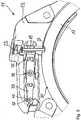
- the Figs. 1 to 5 show an embodiment of a lock according to the invention.
- This embodiment is a partially automatic frame lock 11, which is intended in particular for two-wheelers.
- the frame lock 11 comprises a lock body 13, of which in the Figs. 1 to 4 only a plate 15 delimiting an interior of the lock body 13, in Fig. 5 however, parts of other elements are shown.
- the frame lock 11 further comprises a partially circular arch-shaped bracket 17, which is only partially shown and between the in the Figs. 1 and 2 shown closed position and in the Fig. 4 and 5 open position shown is movable.
- the state of the lock shown is the bracket 17 in an intermediate position between the closed position and the open position.
- the bracket 17 is guided by the lock body 13 on a circular path, along which the partial circular arc shape of the bracket 17 also extends.
- the frame lock 11 is designed to be arranged in this way on a wheel of a two-wheeler to be that the bracket 17 engages between the spokes of the wheel in the closed position and thereby blocks it, while in the open position it releases the wheel.
- the bracket 17 can be pretensioned in the open position.
- the basic mobility of the bracket 17 is restricted by a bolt 19 of the lock 11, which is mounted on the lock body 13 so as to be movable essentially radially to the partially circular arc shape of the bracket 17.
- the bolt 19 can engage in a first engagement recess 21 of the bracket 17 which extends radially from the outside into the bracket 17.
- this state which is in the Figs. 1 and 2 is shown, locks the bolt 19 by engaging in the first engagement recess 21, the bracket 17 against leaving the closed position and is in this respect in its locking position.
- the bolt 19 can be displaced radially outward so that it emerges from the first engagement recess 21 and is arranged radially outside the outer radius of the bracket 17.
- the bracket 17 is released for leaving the closed position, so that the bolt 19 is in this respect in its unlocked position.
- the unlocking position is not necessarily limited to a single position of the bolt 19, but can encompass the entire range of bolt positions in which the bracket 17 is released for moving from the closed position to the open position and back.
- the unlocked position of the bolt 19 is for example in Fig. 3 shown.
- the lock comprises a spring 23 which acts on the bolt 19 and thereby biases it against the bracket 17. As long as the bolt 19 is not moved or held against this bias, the bolt 19 therefore rests against an outer contour 25 of the bracket 17. Where the bolt 19 rests along this contour 25 depends on the respective position of the bracket 17.
- the first engagement recess 21 forms that part of the contour 25 against which the bolt 19 rests in the closed position of the bracket 17.
- the contour 25 has an essentially constant radius which corresponds to the outer radius of the bracket 17.
- the bolt 19 rests against this area in intermediate positions of the bracket 17 between its closed position and its open position due to the pretensioning and thereby essentially assumes the position shown in FIG Fig. 3 unlocked position shown.
- the bracket 17 can be opened or closed, the bolt 19, as long as it is not as in Fig. 3 shown by the eccentric 31 is held against the bias of the spring 23 at a distance from the contour 25, slides along the contour 25 of the bracket 17.
- the contour 25 extends from the first engagement recess 21 over the area with constant radius to a second engagement recess 27, which extends radially from the outside into the bracket 17 and in which the bolt 19 engages due to the bias of the spring 23 when the Bracket 17 is in the open position.
- the second engagement recess 27 has a smaller depth than the first engagement recess 21 Fig. 4 and 5
- the position shown of the latch 19 engaging in the second engagement recess 27 from the locking position in which it is located when it engages in the first engagement recess 21.
- the locking position shown represents a locking position of the locking bar 19 that is to be distinguished from the locking position and the unlocking position.
- the bolt 19 can be displaced radially outward by a motor with respect to the partial circular arc shape of the bracket 17.
- a drive motor 29 is provided, which is designed as an electric motor in the exemplary embodiment shown.
- An output shaft of the drive motor 29 drives an eccentric 31, which engages in an opening of the essentially disk-shaped bolt 19, so that the bolt 19, depending on the rotational position of the eccentric 31, is offset radially outward against the bias and basically also held in a certain position can.
- the drive motor 29, however, is only used to move the bracket 17 to leave the closed position ( Figs. 1 and 2 ) or the open position ( Fig. 4 and 5 ) by briefly pulling the bolt 19 out of its locked position ( Figs.
- the state of the bracket 17 can also be determined on the basis of the respective position of the bolt 19. If the bolt 19 is in the locking position, the bracket 17 can only be in the closed position. In a corresponding manner, the bracket 17 can only be in the open position when the bolt 19 is in the secured position. If, on the other hand, the bolt 19 is in the unlocked position, in particular in the position in which it rests against the area of the contour 25 with a constant radius, the bracket 17 is in an intermediate position between the open position and the closed position.
- a lever 33 is provided within the lock body 13, which is arranged essentially parallel to the drive motor 29 and in the Figs. 1 to 4 is largely covered by the drive motor 29.
- the lever 33 can be seen almost completely, since the drive motor 29 and the eccentric 31 in Fig. 5 are hidden.
- the lever 33 is designed as a flat straight rod which extends from a coupling section 35 to a deflection section 37.
- the lever 33 is mounted on the lock body 13 so as to be pivotable about a fulcrum 39.
- the bolt 19 is arranged to be movable essentially tangentially to the pivot axis of the lever 33 defined by the pivot 39.
- the lever 33 is coupled in terms of movement to the bolt 19 via the coupling section 35, so that when the bolt 19 is displaced, the lever 33 is pivoted about the pivot point 39.
- the movement coupling of the lever 33 to the bolt 19 takes place in that the coupling section 35 engages in a recess in the bolt 19.
- the deflecting section 37 leads to a movement of the coupling section 35, a movement that is approximately twice as great in comparison thereto.
- the three positions of the deflection section 37 corresponding to the locking position, the unlocking position and the securing position of the bolt 19 differ more from one another than these bolt positions themselves.
- the locking positions can therefore be distinguished more reliably than if they were detected directly using the locking bar 19.
- the sensor 41 can in this way be arranged outside the dirty area of the bolt 19 and instead in the vicinity of electronics (not shown) which are also provided for controlling the drive motor 29, among other things.
- the sensor 41 is a magnetic sensor in the manner of a Hall sensor or magnetic field sensor, which is designed in particular for three-dimensional magnetic detection.
- the sensor 41 interacts with a permanent magnet 43 which is arranged on the deflection section 37 of the lever 33 and whose magnetic field is detected by the sensor 41.
- the design of the sensor 41 as a 3D sensor makes it possible, by means of a single sensor 41, to reliably differentiate at least the three positions of the deflection section 37 of the lever 33 which, due to the movement coupling of the bolt 19 with the coupling section 35 of the lever 33, of the locking position, the The unlocking position and the locking position of the bolt 19 correspond.
Landscapes
- Engineering & Computer Science (AREA)
- Mechanical Engineering (AREA)
- Physics & Mathematics (AREA)
- Electromagnetism (AREA)
- Lock And Its Accessories (AREA)
Description
- Die vorliegende Erfindung betrifft ein Schloss, insbesondere für ein Zweirad, mit einem Schlosskörper, einem Bügel, der zwischen einer Offenstellung und einer Geschlossenstellung beweglich ist, insbesondere gelagert oder zumindest geführt ist, sowie einem Riegel, der zwischen einer Verriegelungsstellung, in der er den Bügel in dessen Geschlossenstellung gegen ein Verlassen der Geschlossenstellung sperrt, und einer Entriegelungsstellung, in der er den Bügel freigibt, an dem Schlosskörper beweglich gelagert ist. Bei dem Schloss kann es sich insbesondere um ein Rahmenschloss handeln. Der Bügel dient in seiner Geschlossenstellung beispielsweise dazu, einen Gegenstand mittels des Schlosses zu fixieren, z.B. an einem anderen Gegenstand anzuschließen oder eine Bewegung des Gegenstands zu blockieren, etwa nach Art eines Speichenschlosses, das die Drehung eines Rades verhindert. Der Riegel dagegen wirkt typischerweise nicht mit Gegenständen außerhalb des Schlosses, sondern mit dem Bügel zusammen und dient dazu, den Bügel insbesondere in dessen Geschlossenstellung zu sperren bzw. freizugeben, je nachdem, ob das Schloss verriegelt oder entriegelt ist.
- Ein derartiges Schloss kann zur Verbesserung des Komforts halbautomatisch oder vollautomatisch ausgebildet sein, indem es zumindest teilweise motorisch antreibbar ist. Das heißt, dass einzelne Elemente des Schlosses von einem oder mehreren Antriebsmotoren des Schlosses motorisch bewegt werden können. In der Regel lässt sich ein solches Schloss zumindest motorisch entriegeln, d.h. dass der Riegel motorisch aus der Verriegelungsstellung in die Entriegelungsstellung versetzbar ist, um den Bügel für ein Verlassen seiner Geschlossenstellung freizugeben. Der Riegel kann aber auch, zusätzlich oder alternativ, in die umgekehrte Richtung motorisch versetzbar sein. Zudem kann vorgesehen sein, dass (auch) der Bügel motorisch bewegt werden kann. Ein Schloss mit diesen Merkmalen ist beispielsweise aus
CN 201 100 043 Y bekannt. Um ein motorisch antreibbares Element des Schlosses zuverlässig bewegen zu können, ist es zweckmäßig, Informationen über die jeweils aktuelle Stellung des Elements erfassen zu können. Dazu kann beispielsweise ein Sensor vorgesehen sein. Ein solcher Sensor wird insbesondere zum Erfassen der Riegelstellung genutzt. Sofern der Riegel gewisse Stellungen, wie z.B. die Verriegelungsstellung, nur dann einnehmen kann, wenn sich der Bügel in einer bestimmten Stellung, z.B. in der Geschlossenstellung, befindet, kann mittels des die Riegelstellung erfassenden Sensors indirekt auch die Stellung des Bügels feststellbar sein. - Um anhand des Sensors feststellen zu können, ob der Bügel verriegelt oder freigegeben ist, muss der Sensor zwischen der Verriegelungsstellung und der Entriegelungsstellung des Riegels zuverlässig unterscheiden können. Im Bestreben, das Schloss möglichst kompakt auszubilden, kann aber der Hub des Riegels, d.h. die Länge der zwischen der Verriegelungsstellung und der Entriegelungsstellung vom Riegel zurückzulegenden, in der Regel linearen, Strecke, sehr gering sein, so dass sich die Verriegelungsstellung und die Entriegelungsstellung nicht oder nicht zuverlässig voneinander unterscheiden lassen.
- Darüber hinaus muss der Riegel, um den Bügel zu sperren, mit dem Bügel zusammenwirken können. Der Riegel ist daher in der Regel in unmittelbarer Nähe zum Bügel angeordnet, wobei vom Bügel, der mit Gegenständen außerhalb des Schlosses zusammenwirkt, Schmutz von außen auch in den Bereich des Riegels dringen kann. Derartige Verschmutzungen können das Erfassen der Riegelstellung zusätzlich stören und somit erschweren.
- Es ist eine Aufgabe der Erfindung, ein insbesondere zumindest teilweise motorisch antreibbares Schloss bereitzustellen, bei dem die Stellungen beweglicher Elemente des Schlosses, insbesondere die jeweilige Stellung des Riegels sowie vorteilhafterweise auch, zumindest indirekt, die Stellung des Bügels, besonders zuverlässig erfasst werden können.
- Die Aufgabe wird gelöst durch ein Schloss mit den Merkmalen des Anspruchs 1. Vorteilhafte Ausführungsformen der Erfindung ergeben sich aus den Unteransprüchen, den Figuren sowie der vorliegenden Beschreibung.
- Erfindungsgemäß umfasst das Schloss einen beweglich gelagerten Hebel, wobei ein Kopplungsabschnitt des Hebels mit dem Riegel bewegungsgekoppelt ist, wobei der Hebel derart gelagert ist, dass ein von dem Kupplungsabschnitt beabstandeter Auslenkabschnitt des Hebels bei einer Bewegung des Kopplungsabschnitts eine im Vergleich dazu größere Bewegung ausführt, und wobei der Sensor zum Erfassen der Riegelstellung die Stellung des Auslenkabschnitts des Hebels erfasst.
- Der Hebel weist also einerseits einen Kopplungsabschnitt und andererseits einen Auslenkabschnitt auf, die separat voneinander angeordnet sind. Über den Kopplungsabschnitt ist der Hebel dabei mit dem Riegel bewegungsgekoppelt, also insbesondere derart gekoppelt, dass eine Bewegung des Riegels zu einer entsprechenden Bewegung des Kopplungsabschnitts führt und/oder umgekehrt. Die Bewegungen können dabei insbesondere insofern einander entsprechend sein, als sich der Riegel und der Kopplungsabschnitt des Hebels zumindest im Wesentlichen um dasselbe Maß bewegen. Dabei können der Riegel und der Kopplungsabschnitt des Hebels aber auch derart gekoppelt sein, dass eine lineare Bewegung des Riegels zu einer Dreh- oder Schwenkbewegung des Hebels führt und/oder umgekehrt. Der Kopplungsabschnitt muss somit nicht zwangsläufig exakt dieselbe Bewegung wie der Riegel ausführen. Vorzugsweise besteht jedoch aufgrund der Bewegungskopplung zumindest ein eindeutiger Zusammenhang zwischen der jeweiligen Stellung des Riegels und der jeweiligen Stellung des Kopplungsabschnitts. Ferner wirken der Kopplungsabschnitt des Hebels und der Riegel vorzugsweise unmittelbar miteinander zusammen, z.B. durch direktes Ineinandergreifen.
- Der Auslenkabschnitt des Hebels wird durch denjenigen Abschnitt des Hebels gebildet, dessen Stellung vom Sensor, insbesondere unmittelbar, erfasst wird. Vorzugsweise wirkt der Sensor dazu mit dem Auslenkabschnitt des Hebels direkt zusammen. Die Stellung des Riegels wird auf diese Weise dagegen lediglich indirekt erfasst.
- Bei einer Bewegung des Hebels, der vorzugsweise zumindest im Wesentlichen starr ausgebildet ist, bewegt sich aufgrund der Art der Lagerung des Hebels nicht nur der Kopplungsabschnitt, sondern auch der Auslenkabschnitt des Hebels. Das Maß der Bewegung des Auslenkabschnitts ist dabei aber nicht identisch zu dem Maß der Bewegung des Kopplungsabschnitts. Vielmehr erfolgt eine Art Übersetzung, die sich aus der Anordnung des Kopplungsabschnitts und des Auslenkabschnitts relativ zueinander im Zusammenhang mit der Art der Lagerung des Hebels ergibt. Dabei ist die Bewegung des Auslenkabschnitts, die dieser ausführt, wenn sich der Kopplungsabschnitt bewegt, größer als die gleichzeitige Bewegung des Kopplungsabschnitts. Insofern wird die Bewegung des Riegels durch den Hebel also nicht nur vom Kopplungsabschnitt zum Auslenkabschnitt übertragen, sondern dabei zugleich verstärkt.
- Sowohl die Übertragung der Bewegung als auch die Verstärkung tragen dabei zu einer Verbesserung der Zuverlässigkeit des Erfassens der Riegelstellung bei. Denn zum einen kann das Erfassen somit in einem Bereich erfolgen, der außerhalb des sogenannten Schmutzbereichs des Riegels liegen und somit besser vor Verschmutzungen geschützt sein kann. Insbesondere kann der Sensor dadurch flexibler innerhalb des Schlosses, beispielsweise zusammen mit anderen empfindlichen elektronischen Komponenten in einem besonders geschützten Bereich des Schlosses, positioniert werden. Zum anderen lassen sich die verschiedenen Stellungen des Riegels infolge der Verstärkung zuverlässiger unterscheiden. Während der Gesamthub des Riegels wenige Millimeter, vorzugsweise weniger als 5 mm, z.B. etwa 4 mm oder weniger, betragen kann, kann vorgesehen sein, dass der entsprechende Hub des Auslenkabschnitts zumindest das Anderthalbfache, vorzugsweise zumindest das Doppelte, des Riegelhubs beträgt. Da idealerweise über den Hebel und die Bewegungskopplung des Hebels mit dem Riegel ein eindeutiger Zusammenhang zwischen der Stellung des Riegels und der Stellung des Auslenkabschnitts besteht (von möglichst geringfügigem Spiel abgesehen), liegen die Stellungen des Auslenkabschnitts, die der Entriegelungsstellung bzw. der Verriegelungsstellung des Riegels entsprechen, aufgrund der vergrößerten Bewegung weiter auseinander als die genannten Riegelstellungen. Dadurch kann sich das Zusammenwirken des Sensors mit dem Auslenkabschnitt in diesen beiden Stellungen stärker unterscheiden und somit zu einer zuverlässigeren Erfassung führen, als wenn der Sensor direkt mit dem Riegel zusammenwirken würde.
- Der Hebel kann beispielsweise um einen Drehpunkt schwenkbar gelagert sein. Die Verstärkung zwischen dem Kopplungsabschnitt und dem Auslenkabschnitt ergibt sich dann direkt aus dem Verhältnis der jeweiligen Abstände der beiden Abschnitte vom Drehpunkt. Zudem ist die Verstärkung bei einer solchen schwenkbaren Lagerung konstant. Grundsätzlich kommen aber auch andere Arten der Lagerung in Betracht, darunter auch solche, bei denen die Verstärkung variiert. Abweichungen von einer exakt konstanten Verstärkung können sich zudem auch aus der Art der Bewegungskupplung des Kopplungsabschnitts des Hebels mit dem Riegel ergeben, z.B. wenn die Bewegung des Riegels linear ist, während der Kopplungsabschnitt eines schwenkbaren Hebels eine Teilkreisbahn durchläuft.
- Der Drehpunkt kann insbesondere zwischen dem Kopplungsabschnitt und dem Auslenkabschnitt vorgesehen sein. Dies ermöglicht eine vergleichsweise einfache Lagerung des Hebels und Kopplung des Riegels mit dem Hebel. Grundsätzlich können der Kopplungsabschnitt und der Auslenkabschnitt aber auch auf derselben Seite des Drehpunktes angeordnet sein. Auf diese Weise können mit einem vergleichsweise kurzen Hebel vergleichsweise große Verstärkungen des jeweiligen Ausmaßes der Bewegung zwischen dem Kopplungsabschnitt und dem Auslenkabschnitt erzielt werden, was besonders kompakte Ausführungsformen ermöglicht.
- Der Hebel kann beispielsweise zumindest im Wesentlichen stabförmig sein. Insbesondere in diesem Fall können der Kopplungsabschnitt, der Auslenkabschnitt und der Drehpunkt auf einer geraden Linie liegen, die der Längserstreckung des Hebels entsprechen kann. Des Weiteren kann der Kopplungsabschnitt an einem ersten Ende des Hebels und kann der Auslenkabschnitt an einem dem ersten Ende entgegengesetzten zweiten Ende des Hebels vorgesehen sein. Die Enden des Hebels sind dabei insbesondere Enden bezüglich der genannten Längserstreckung des Hebels.
- Gemäß einer vorteilhaften Ausführungsform ist der Bügel zumindest teilweise innerhalb des Schlosskörpers angeordnet, wobei der Riegel sowie der Hebel vollständig innerhalb des Schlosskörpers angeordnet sind. Denn während der Bügel mit Gegenständen außerhalb des Schlosses zusammenwirken muss, ist es insbesondere im Hinblick auf die Sicherheit des Schlosses vorteilhaft, wenn der Riegel und der Hebel von außen nicht zugänglich sind. Der Hebel ermöglicht dabei eine flexible Positionierung des Sensors, der ebenfalls vorteilhafterweise in dem Schloss angeordnet sowie von außen nicht zugänglich ist und aufgrund des Hebels nicht auf eine Anordnung in der Nähe des Riegels beschränkt ist. Durch diese Anordnung des Hebels und/oder des Sensors kann die Stellungserfassung außerhalb des Schmutzbereichs des Riegels sowie insbesondere auch in einem verkapselten oder auf andere Weise besonders gesicherten Bereich des Schlosskörpers erfolgen.
- Des Weiteren ist es bevorzugt, dass der Auslenkabschnitt mit dem Sensor magnetisch zusammenwirkt. Auf diese Weise kann das Erfassen der Stellung des Auslenkabschnitts mittels des Sensors vorteilhafterweise kontaktlos erfolgen. Das ermöglicht es, den Sensor ebenso wie weitere Elektronik des Schlosses gegenüber mechanischen Elementen, wie insbesondere dem Hebel und dem Riegel, räumlich isoliert anzuordnen.
- Beispielsweise kann der Sensor als magnetischer Sensor ausgebildet sehr, der mit einem Permanentmagneten zusammenwirkt, den der Auslenkabschnitt aufweist. Insbesondere kann der Auslenkabschnitt zumindest im Wesentlichen durch den Permanentmagneten definiert sein. Grundsätzlich kann der Sensor beispielsweise als einfacher Magnetschalter ausgebildet sein. Vorzugsweise ist der Sensor aber als Hall-Sensor oder Magnetfeldsensor ausgebildet. Besonders vorteilhaft ist es dabei, wenn der Sensor zur dreidimensionalen magnetischen Erfassung ausgebildet ist. Das heißt beispielsweise, dass es möglich ist, mittels des Sensors die Position eines Permanentmagneten im Raum zu bestimmen, oder dass sich mittels des Sensors nicht nur die Stärke eines Magnetfeldes, sondern auch dessen räumliche Ausrichtung bestimmen lässt. Auf diese Weise können auch mehr als zwei Zustände mittels eines einzelnen Sensors unterschieden und unter Umständen ganze Bewegungsbahnen nachvollzogen werden.
- Das magnetische Zusammenwirken des Auslenkabschnitts mit dem Sensor ermöglicht ferner eine Ausführungsform, bei der das Schloss ein innerhalb des Schlosskörpers angeordnetes, vorzugsweise vollumfänglich geschlossenes, Innengehäuse umfasst, wobei der Sensor innerhalb des Innengehäuses angeordnet ist und der Hebel außerhalb des Innengehäuses angeordnet ist. Der Auslenkabschnitt und der Sensor wirken dabei also durch das Innengehäuse hindurch magnetisch zusammen. Auf diese Weise kann der Sensor gegebenenfalls mit sonstiger Elektronik und/oder sonstigen besonders zu schützenden Komponenten des Schlosses durch das Innengehäuse gegenüber den übrigen Komponenten des Schlosses eingekapselt sein. Das Innengehäuse ist dabei vorteilhafterweise nicht magnetisch und vorzugsweise gegenüber einem äußeren Gehäuse des Schlosses verstärkt ausgebildet, z.B. aus einem gehärteten Material, insbesondere aus gehärtetem Metall.
- Gemäß einer weiteren vorteilhaften Ausführungsform ist der Hebel derart gelagert, dass er einen einzigen Freiheitsgrad aufweist. Dies ist insbesondere zweckmäßig, wenn auch der Riegel lediglich einen Freiheitsgrad aufweist. Wenn nur ein Freiheitsgrad vorliegt, kann der Hebel nur entlang einer definierten Bewegungsbahn, allerdings in zwei entgegengesetzte Richtungen, bewegt werden. Insbesondere durch eine derart eingeschränkte Beweglichkeit können vom Sensor erfasste Messwerte speziell im Hinblick darauf unterschieden werden, ob sie sich einer möglichen Stellung des Auslenkabschnitts, d.h. insbesondere einer Stellung entlang der definierten Bewegungsbahn des Auslenkabschnitts, zuordnen lassen oder nicht. Ist eine Zuordnung nicht möglich, kann der erfasste Messwert als Hinweis auf einen Manipulationsversuch an dem Schloss zu werten sein, bei dem der Hebel von seiner üblichen Bewegungsbahn abgebracht wird oder bei dem versucht wird, mittels externer Magnetfelder auf das Schloss einzuwirken. Im Zusammenhang mit einer derartigen Detektion von Manipulationsversuchen sind insbesondere die genannten zur dreidimensionalen magnetischen Erfassung ausgebildeten Sensoren vorteilhaft, da sie differenziertere Informationen bereitstellen als magnetische Sensoren, die lediglich den Abstand eines Magneten vom Sensor oder lediglich den Absolutbetrag der Stärke eines Magnetfeldes erfassen.
- Gemäß einer weiteren vorteilhaften Ausführungsform umfasst das Schloss einen Antriebsmotor zum Bewegen des Riegels. Der Antriebsmotor kann zudem auch zum Bewegen des Bügels vorgesehen sein. Das Schloss kann auch zusätzlich zu dem genannten Antriebsmotor einen oder mehrere weitere Antriebsmotoren zum Bewegen des Bügels und/oder weiterer beweglicher Elemente des Schlosses aufweisen.
- Wenn in dem Schoss ein Antriebsmotor zum Bewegen des Riegels vorgesehen ist, ist der Hebel vorzugsweise im Wesentlichen parallel zum Antriebsmotor ausgerichtet. Dabei ist insbesondere eine Längserstreckung des Hebels, z.B. eine Verbindungslinie zwischen dem Kopplungsabschnitt und dem Auslenkabschnitt des Hebels, parallel zu einer Rotationsachse einer Abtriebswelle des Antriebsmotors und/oder zu einer Längserstreckung des Antriebsmotors angeordnet. Insbesondere kann der Hebel im Rahmen seiner Beweglichkeit zumindest eine Stellung einnehmen, die einer Stellung des Riegels auf dessen Bewegungsbahn zwischen der Verriegelungsstellung und der Entriegelungsstellung entspricht und in der der Hebel parallel zum Antriebsmotor ausgerichtet ist.
- Dabei ist der Kopplungsabschnitt des Hebels vorzugsweise im Bereich einer Abtriebswelle des Antriebsmotors angeordnet und der Auslenkabschnitt des Hebels im Bereich elektrischer Anschlüsse des Antriebsmotors angeordnet. Denn auf diese Weise können die Abtriebswelle des Antriebsmotors bzw. ein die Abtriebswelle mit dem Riegel antriebswirksam verbindendes Übertragungselement sowie der Kopplungsabschnitt des Hebels auf der einen Seite mit dem Riegel zusammenwirken und die Anschlüsse des Antriebsmotors sowie der Auslenkabschnitt des Hebels auf der anderen Seite mit dem Sensor bzw. sonstigen elektronischen Komponenten, z.B. einer Auswerte- und Steuereinheit, die auch mit dem Sensor verbunden ist, zusammenwirken, ohne dass dafür größere räumliche Distanzen zu überwinden wären.
- Gemäß einer weiteren vorteilhaften Ausführungsform weist der Bügel eine erste Eingriffsvertiefung auf, in die der Riegel, wenn der Bügel in der Geschlossenstellung ist, eingreifen kann, um den Bügel gegen ein Verlassen der Geschlossenstellung zu sperren. Vorzugsweise weist der Bügel ferner eine zweite Eingriffsvertiefung auf, in die der Riegel, wenn der Bügel in der Offenstellung ist, eingreifen kann, um den Bügel gegen ein Verlassen der Offenstellung zu sperren. Bei einer solchen Ausführungsform kann also zusätzlich zur Geschlossenstellung auch die Offenstellung durch den Riegel gesichert werden. Das ist beispielsweise bei automatischen Rahmenschlössern vorteilhaft, bei denen es wichtig ist sicherzustellen, dass sich Bügel nicht versehentlich, vor allem nicht während der Fahrt, schließt. Die Stellung, die der Riegel einnimmt, wenn er vollständig in die erste Eingriffsvertiefung des Bügels eingreift, entspricht insbesondere der genannten Verriegelungsstellung. Die Stellung, die der Riegel einnimmt, wenn er vollständig in die zweite Eingriffsvertiefung des Bügels eingreift, könnte grundsätzlich ebenfalls der Verriegelungsstellung entsprechen. Im Rahmen der Erfindung handelt es sich jedoch um eine sowohl von der Verriegelungsstellung als auch von der Entriegelungsstellung des Riegels verschiedene Sicherungsstellung des Riegels, wie nachstehend erläutert wird.
- Erfindungsgemäß ist der Riegel gegen den Bügel vorgespannt, so dass er an einer Kontur des Bügels anliegt, zumindest solange er nicht entgegen der Vorspannung, z.B. durch einen Antriebsmotor des Schlosses, bewegt oder gehalten wird. Bei einer Bewegung des Bügels kann der Riegel dabei an der Kontur, zumindest an Bereichen der Kontur, die keine stufenartigen Sprünge aufweisen, entlanggleiten. Dabei ist die Kontur des Bügels derart ausgebildet, dass der Riegel infolge der Vorspannung, in der Geschlossenstellung des Bügels seine Verriegelungsstellung einnimmt, in Stellungen des Bügels, die zwischen der Geschlossenstellung und der Offenstellung des Bügels liegen, seine Entriegelungsstellung einnimmt und in der Offenstellung des Bügels eine von der Verriegelungsstellung und der Entriegelungsstellung verschiedene Sicherungsstellung einnimmt. Vorzugsweise liegt die Sicherungsstellung entlang der Beweglichkeit des Riegels zwischen dessen Vierregelungsstellung und dessen Entriegelungsstellung.
- Des Weiteren kann bei einer solchen Ausführungsform vorgesehen sein, dass die Kontur des Bügels die genannte erste Eingriffsvertiefung und die genannte zweite Eingriffsvertiefung aufweist, so dass der Riegel infolge der Vorspannung in der Geschlossenstellung des Bügels in die erste Eingriffsvertiefung eingreift, wobei durch die Tiefe des Eingreifens die Verriegelungsstellung des Riegels definiert wird, und in der Offenstellung des Bügels in die zweite Eingriffsvertiefung eingreift, wobei durch die Tiefe des Eingreifens die Sicherungsstellung des Riegels definiert wird.
- Die gegenüber der Bewegung des Riegels verstärkte Bewegung des mit dem Sensor zusammenwirkenden Auslenkabschnitts des Hebels ist insbesondere aufgrund der zusätzlich zu der Verriegelungsstellung und der Entriegelungsstellung des Riegels definierten Sicherungsstellung des Riegels vorteilhaft, derentwegen zumindest drei verschiedene Stellungen zu unterscheiden sind. Denn je mehr Riegelstellungen zu unterscheiden sind, desto schwieriger ist deren Unterscheidung, insbesondere bei einem Riegel mit geringem Gesamthub. Indem die Riegelstellung nicht direkt erfasst wird, sondern anhand der Stellung des Auslenkabschnitts des mit dem Riegel bewegungsgekoppelten Hebels, lassen sich jedoch auch mehr als zwei Stellungen des Riegels zuverlässig zu unterscheiden.
- Erfindungsgemäß ausgebildete Schlösser, bei denen der Riegel gegen eine Kontur des Bügels vorgespannt ist, ermöglichen zudem, anhand der (über den Auslenkabschnitt des Hebels) erfassten Riegelstellung auch die Stellung des Bügels zu ermitteln. Denn aufgrund der Vorspannung wird, solange der Riegel nicht entgegen der Vorspannung bewegt oder gehalten wird, die Stellung des Riegels dadurch bestimmt, an welcher Stelle der Kontur des Bügels der Riegel gerade anliegt, was wiederum von der Stellung des Bügels abhängt. Dabei kann die Kontur insbesondere zumindest drei verschiedene Niveaus aufweisen, die somit zu einer entsprechenden Anzahl von Riegelstellungen führen und derart angeordnet sind, dass: der Riegel in der Geschlossenstellung des Bügels auf Höhe eines ersten Niveaus an der Kontur anliegt, das insbesondere der genannten ersten Eingriffsvertiefung entsprechen kann, und dadurch seine Verriegelungsstellung einnimmt; in der Offenstellung der Bügels auf Höhe eines zweiten Niveaus an der Kontur anliegt, das insbesondere der genannten zweiten Eingriffsvertiefung entsprechend kann, und dadurch seine Sicherungsstellung einnimmt; und in Stellungen des Bügels zwischen der Geschlossenstellung und der Offenstellung auf Höhe eines dritten Niveaus an der Kontur anliegt. Die diesem dritten Niveau entsprechende Stellung des Riegels kann dann als Hinweis darauf gewertet werden, dass der Bügel sich gerade irgendwo zwischen der Geschlossenstellung und der Offenstellung befindet, insbesondere gerade bewegt, zumal der Riegel den Bügel in dieser Stellung vorteilhafterweise nicht sperrt. Insofern entspricht diese Riegelstellung der Entriegelungsstellung des Riegels. Dabei muss die Entriegelungsstellung des Riegels nicht zwangsläufig auf eine einzige Riegelstellung festgelegt sein, sondern kann auch einen Bereich von Riegelstellungen umfassen, nämlich insbesondere all diejenigen Stellungen, in denen der Bügel durch den Riegel für eine Bewegung aus der Geschlossenstellung in die Offenstellung und/oder umgekehrt freigegeben ist. Insbesondere kann insofern auch eine (oder jede) Stellung, in die der Riegel entgegen der Vorspannung so weit motorisch verstellt wird, dass er über das oberste Niveau der Kontur des Bügels hinaus versetzt ist und somit zwangsläufig den Bügel freigibt, der Entriegelungsstellung des Riegels entsprechen.
- Die Erfindung wird nachfolgend lediglich beispielhaft unter Bezugnahme auf die Figuren weiter erläutert.
- Fig. 1
- zeigt in einer perspektivischen schematischen Darstellung Teile einer Ausführungsform des erfindungsgemäßen Schlosses, wobei sich der Bügel in der Geschlossenstellung befindet und sich der Riegel in der Verriegelungsstellung befindet.
- Fig. 2
- zeigt dieselbe Ausführungsform mit denselben Stellungen wie in
Fig. 1 , jedoch aus einem anderen Blickwinkel. - Fig. 3
- entspricht weitgehend der
Fig. 2 , wobei jedoch der Bügel eine Zwischenstellung einnimmt und sich der Riegel in der Entriegelungsstellung befindet. - Fig. 4
- entspricht weitgehend der
Fig. 2 , wobei sich jedoch der Bügel in der Offenstellung befindet und sich der Riegel in der Sicherungsstellung befindet. - Fig. 5
- zeigt dieselbe Ausführungsform wie in
Fig. 1 bis 4 in einer perspektivischen schematischen Ausschnittsdarstellung, wobei teilweise andere Teile des Schlosses dargestellt sind als inFig. 1 bis 4 . - Die
Fig. 1 bis 5 zeigen eine Ausführungsform eines erfindungsgemäßen Schlosses. Bei dieser Ausführungsform handelt es sich um ein teilautomatisches Rahmenschloss 11, das insbesondere für Zweiräder gedacht ist. Das Rahmenschloss 11 umfasst einen Schlosskörper 13, von dem in denFig. 1 bis 4 lediglich eine einen Innenraum des Schlosskörpers 13 begrenzende Platte 15, inFig. 5 jedoch ausschnittsweise weitere Elemente gezeigt sind. - Das Rahmenschloss 11 umfasst ferner einen teilkreisbogenförmigen Bügel 17, der jeweils nur teilweise gezeigt ist und der zwischen der in den
Fig. 1 und 2 gezeigten Geschlossenstellung und der in denFig. 4 und5 gezeigten Offenstellung beweglich ist. In dem inFig. 3 gezeigten Zustand des Schlosses befindet sich der Bügel 17 in einer Zwischenstellung zwischen der Geschlossenstellung und der Offenstellung. Der Bügel 17 wird durch den Schlosskörper 13 auf einer Kreisbahn geführt, entlang der sich auch die Teilkreisbogenform des Bügels 17 erstreckt. Das Rahmenschloss 11 ist dazu ausgebildet, derart an einem Rad eines Zweirades angeordnet zu werden, dass der Bügel 17 in der Geschlossenstellung zwischen Speichen des Rades greift und es dadurch blockiert, in der Offenstellung dagegen das Rad freigibt. Dabei kann der Bügel 17 in die Offenstellung vorgespannt sein. - Die grundsätzliche Beweglichkeit des Bügels 17 wird durch einen Riegel 19 des Schlosses 11 eingeschränkt, der im Wesentlichen radial zur Teilkreisbogenform des Bügels 17 beweglich an dem Schlosskörper 13 gelagert ist. Dabei kann der Riegel 19, wenn sich der Bügel 17 in seiner Geschlossenstellung befindet, in eine erste Eingriffsvertiefung 21 des Bügels 17 eingreifen, die sich radial von außen in den Bügel 17 erstreckt. In diesem Zustand, der in den
Fig. 1 und 2 gezeigt ist, sperrt der Riegel 19 durch das Eingreifen in die erste Eingriffsvertiefung 21 den Bügel 17 gegen ein Verlassen der Geschlossenstellung und befindet sich insofern in seiner Verriegelungsstellung. - Aus dieser Verriegelungsstellung kann der Riegel 19 radial nach außen versetzt werden, so dass er aus der ersten Eingriffsvertiefung 21 austritt und radial außerhalb des Außenradius des Bügels 17 angeordnet ist. Dadurch wird der Bügel 17 für ein Verlassen der Geschlossenstellung freigegeben, so dass sich der Riegel 19 insofern in seiner Entriegelungsstellung befindet. Die Entriegelungsstellung ist dabei nicht unbedingt auf eine einzige Stellung des Riegels 19 beschränkt, sondern kann den gesamten Bereich von Riegelstellungen umfassen, in denen der Bügel 17 für ein Bewegen von der Geschlossenstellung in die Offenstellung und zurück freigegeben ist. Die Entriegelungsstellung des Riegels 19 ist beispielsweise in
Fig. 3 gezeigt. - Des Weiteren umfasst das Schloss eine Feder 23, die den Riegel 19 beaufschlagt und dadurch gegen den Bügel 17 vorspannt. Solange der Riegel 19 nicht entgegen dieser Vorspannung bewegt oder gehalten wird, liegt der Riegel 19 daher an einer äußeren Kontur 25 des Bügels 17 an. Wo entlang dieser Kontur 25 der Riegel 19 jeweils anliegt, hängt dabei von der jeweiligen Stellung des Bügels 17 ab.
- Die erste Eingriffsvertiefung 21 bildet dabei denjenigen Teil der Kontur 25, gegen den der Riegel 19 in der Geschlossenstellung des Bügels 17 anliegt. In einem Bereich, der sich an die erste Eingriffsvertiefung 21 anschließt, weist die Kontur 25 einen im Wesentlichen konstanten Radius auf, der dem Außenradius des Bügels 17 entspricht. An diesem Bereich liegt der Riegel 19 in Zwischenstellungen des Bügels 17 zwischen dessen Geschlossenstellung und Offenstellung aufgrund der Vorspannung an und nimmt dadurch im Wesentlichen die in
Fig. 3 gezeigte Entriegelungsstellung ein. In der Entriegelungsstellung des Riegels 19 kann der Bügel 17 geöffnet oder geschlossen werden, wobei der Riegel 19, solange er nicht wie inFig. 3 gezeigt durch den Exzenter 31 entgegen der Vorspannung der Feder 23 in einem Abstand zur Kontur 25 gehalten wird, an der Kontur 25 des Bügels 17 entlanggleitet. - Die Kontur 25 erstreckt sich von der ersten Eingriffsvertiefung 21 über den Bereich mit konstantem Radius bis zu einer zweiten Eingriffsvertiefung 27, die sich radial von außen in den Bügel 17 erstreckt und in die der Riegel 19 aufgrund der Vorspannung der Feder 23 eingreift, wenn sich der Bügel 17 in der Offenstellung befindet. Gegenüber dem Bereich der Kontur 25 mit konstantem Radius weist die zweite Eingriffsvertiefung 27 eine geringere Tiefe auf als die erste Eingriffsvertiefung 21. Dadurch unterscheidet sich die in den
Fig. 4 und5 gezeigte Stellung des in die zweite Eingriffsvertiefung 27 eingreifenden Riegels 19 von der Verriegelungsstellung, in der er sich befindet, wenn er in die erste Eingriffsvertiefung 21 eingreift. Durch das Eingreifen des Riegels 19 in die zweite Eingriffsvertiefung 27 wird der Bügel 17 an einem Verlassen seiner Öffnungsstellung gehindert, so dass der Bügel 17 gegen ein Schließen gesichert ist. Die in denFig. 4 und5 gezeigte Riegelstellung stellt insofern eine von der Verriegelungsstellung und der Entriegelungsstellung zu unterscheidende Sicherungsstellung des Riegels 19 dar. - Entgegen der Vorspannung der Feder 23 kann der Riegel 19 bezüglich der Teilkreisbogenform des Bügels 17 radial nach außen motorisch versetzt werden. Dazu ist ein Antriebsmotor 29 vorgesehen, der bei der gezeigten beispielhaften Ausführungsform als Elektromotor ausgebildet ist. Eine Abtriebswelle des Antriebsmotors 29 treibt einen Exzenter 31 an, der in eine Öffnung des im Wesentlichen scheibenförmigen Riegels 19 eingreift, so dass der Riegel 19 je nach Drehstellung des Exzenters 31 gegen die Vorspannung radial nach außen versetzt und grundsätzlich auch in einer bestimmten Stellung gehalten werden kann. Der Antriebsmotor 29 wird jedoch lediglich dazu genutzt, den Bügel 17 für ein Verlassen der Geschlossenstellung (
Fig. 1 und 2 ) bzw. der Offenstellung (Fig. 4 und5 ) freizugeben, indem der Riegel 19 kurzzeitig aus seiner Verriegelungsstellung (Fig. 1 und 2 ) bzw. seiner Sicherungsstellung (Fig. 4 und5 ) radial nach außen versetzt wird, so dass der Eingriff des Riegels 19 in die erste Eingriffsvertiefung 21 bzw. in die zweite Eingriffsvertiefung 27 aufgehoben wird. Sobald sich der Bügel 17 daraufhin aus der Geschlossenstellung bzw. Offenstellung bewegt hat, kann der Antriebsmotor 29 deaktiviert werden, so dass der Riegel 19 wieder durch die Vorspannung der Feder 23 gegen den Bügel 17 gedrängt wird und an dem Bereich der Kontur 25 mit konstantem Radius anliegt. Der Bügel 17 ist dadurch für ein Bewegen zwischen seiner Geschlossenstellung und seiner Offenstellung freigegeben. - Da der Riegel 19 infolge der Vorspannung an der Kontur 25 anliegt, solange er nicht vorübergehend entgegen der Vorspannung versetzt oder gehalten wird, lässt sich anhand der jeweiligen Stellung des Riegels 19 auch der Zustand des Bügels 17 feststellen. Befindet sich der Riegel 19 in der Verriegelungsstellung, kann der Bügel 17 nur in der Geschlossenstellung sein. In entsprechender Weise kann der Bügel 17 nur in der Offenstellung sein, wenn sich der Riegel 19 in der Sicherungsstellung befindet. Befindet sich der Riegel 19 dagegen in der Entriegelungsstellung, insbesondere in der Stellung, in der er an dem Bereich der Kontur 25 mit konstantem Radius anliegt, so befindet sich der Bügel 17 in einer Zwischenstellung zwischen der Offenstellung und der Geschlossenstellung. Voraussetzung dafür, dass sich diese Information erfassen lässt, ist aber, dass sich die Verriegelungsstellung, die Sicherungsstellung und die Entriegelungsstellung zuverlässig unterscheiden lassen, obwohl der Hub des Riegels 19, der insbesondere durch den Abstand der in den
Fig. 1 und 2 gezeigten Verriegelungsstellung von der inFig. 3 gezeigten Entriegelungsstellung definiert wird, unter Umständen sehr gering ist, im vorliegenden Beispiel etwa lediglich 4 mm beträgt. - Für eine dennoch zuverlässige Erfassung der Riegelstellung ist innerhalb des Schlosskörpers 13 ein Hebel 33 vorgesehen, der im Wesentlichen parallel zum Antriebsmotor 29 angeordnet ist und in den
Fig. 1 bis 4 größtenteils vom Antriebsmotor 29 verdeckt wird. InFig. 5 ist der Hebel 33 dagegen nahezu vollständig zu sehen, da der Antriebsmotor 29 sowie der Exzenter 31 inFig. 5 ausgeblendet sind. Der Hebel 33 ist als flacher gerader Stab ausgebildet, der sich von einem Kopplungsabschnitt 35 bis zu einem Auslenkabschnitt 37 erstreckt. Dabei ist der Hebel 33 um einen Drehpunkt 39 schwenkbar an dem Schlosskörper 13 gelagert. Die Riegel 19 ist dabei im Wesentlichen tangential zu der durch den Drehpunkt 39 definierten Schwenkachse des Hebels 33 beweglich angeordnet. Über den Kopplungsabschnitt 35 ist der Hebel 33 mit dem Riegel 19 bewegungsgekoppelt, so dass bei einem Versetzen des Riegels 19 der Hebel 33 um den Drehpunkt 39 verschwenkt wird. Die Bewegungskopplung des Hebels 33 mit dem Riegel 19 erfolgt dabei dadurch, dass der Kopplungsabschnitt 35 in eine Aussparung des Riegels 19 eingreift. - Da der Kopplungsabschnitt 35 an einem ersten Ende des Hebels 33 vorgesehen ist und der Auslenkabschnitt 37 an einem dem ersten Enden entgegengesetzten zweiten Ende des Hebels 33 in etwa doppelt so großem Abstand von dem Drehpunkt 39 vorgesehen ist wie der Kopplungsabschnitt 35, führt der Auslenkabschnitt 37 bei einer Bewegung des Kopplungsabschnitts 35 eine im Vergleich dazu etwa doppelt so große Bewegung aus. Auf diese Weise unterscheiden sich die drei der Verriegelungsstellung, der Entriegelungsstellung und der Sicherungsstellung des Riegels 19 entsprechenden Stellungen des Auslenkabschnitts 37 stärker voneinander als diese Riegelstellungen selbst. Mittels eines Sensors 41 (vgl.
Fig. 2 und3 ), der benachbart zum Auslenkabschnitt 37 des Hebels 33 angeordnet ist und die Stellung des Auslenkabschnitts 37 erfasst, lassen sich die Riegelstellungen daher zuverlässiger unterscheiden, als wenn sie direkt anhand des Riegels 19 erfasst würden. Zudem kann der Sensor 41 auf diese Weise außerhalb des Schmutzbereichs des Riegels 19 und stattdessen in der Nähe einer unter anderem auch zur Ansteuerung des Antriebsmotors 29 vorgesehenen Elektronik (nicht dargestellt) angeordnet werden. - Bei dem Sensor 41 handelt es sich um einen magnetischen Sensor nach Art eines Hall-Sensors oder Magnetfeldsensors, der insbesondere zur dreidimensionalen magnetischen Erfassung ausgebildet ist. Der Sensor 41 wirkt dabei mit einem am Auslenkabschnitt 37 des Hebels 33 angeordneten Permanentmagneten 43 zusammen, dessen Magnetfeld der Sensor 41 erfasst. Die Ausbildung des Sensors 41 als 3D-Sensor ermöglicht es dabei, mittels eines einzigen Sensors 41 zumindest die drei Stellungen des Auslenkabschnitts 37 des Hebels 33 zuverlässig zu unterscheiden, die aufgrund der Bewegungskopplung des Riegels 19 mit dem Kopplungsabschnitt 35 des Hebels 33 der Verriegelungsstellung, der Entriegelungsstellung und der Sicherungsstellung des Riegels 19 entsprechen.
-
- 11
- Rahmenschloss
- 13
- Schlosskörper
- 15
- Platte
- 17
- Bügel
- 19
- Riegel
- 21
- erste Eingriffsvertiefung
- 23
- Feder
- 25
- Kontur
- 27
- zweite Eingriffsvertiefung
- 29
- Antriebsmotor
- 31
- Exzenter
- 33
- Hebel
- 35
- Kopplungsabschnitt
- 37
- Auslenkabschnitt
- 39
- Drehpunkt
- 41
- Sensor
- 43
- Permanentmagnet
Claims (14)
- Schloss (11), insbesondere für ein Zweirad, vorzugsweise zumindest teilweise motorisch antreibbar, mit- einem Schlosskörper (13),- einem Bügel (17), der zwischen einer Offenstellung und einer Geschlossenstellung beweglich ist,- einem Riegel (19), der zwischen einer Verriegelungsstellung, in der er den Bügel (17) in dessen Geschlossenstellung gegen ein Verlassen der Geschlossenstellung sperrt, und einer Entriegelungsstellung, in der er den Bügel (17) freigibt, an dem Schlosskörper (13) beweglich gelagert ist,- einem Sensor (41) zum Erfassen der Riegelstellung, sowie- einem beweglich gelagerten Hebel (33),wobei ein Kopplungsabschnitt (35) des Hebels (33) mit dem Riegel (19) bewegungsgekoppelt ist,wobei der Hebel (33) derart gelagert ist, dass ein von dem Kopplungsabschnitt (35) beabstandeter Auslenkabschnitt (37) des Hebels (33) bei einer Bewegung des Kopplungsabschnitts (35) eine im Vergleich dazu größere Bewegung ausführt,wobei der Sensor (41) zum Erfassen der Riegelstellung die Stellung des Auslenkabschnitts (37) des Hebels (33) erfasst,wobeider Riegel (19) gegen den Bügel (17) vorgespannt ist, so dass er an einer Kontur (25) des Bügels (17) anliegt,wobeidie Kontur (25) des Bügels (17) derart ausgebildet ist, dass der Riegel (19) infolge der Vorspannungund wobei mittels des Sensors (41) zumindest die drei Stellungen des Auslenkabschnitts (37) des Hebels (33) zuverlässig zu unterscheiden sind, die der Verriegelungsstellung, der Entriegelungsstellung und der Sicherungsstellung des Riegels (19) entsprechen.- in der Geschlossenstellung des Bügels (17) seine Verriegelungsstellung einnimmt,- in Stellungen des Bügels (17), die zwischen der Geschlossenstellung und der Offenstellung des Bügels (17) liegen, seine Entriegelungsstellung einnimmt und- in der Offenstellung des Bügels (17) eine von der Verriegelungsstellung und der Entriegelungsstellung verschiedene Sicherungsstellung einnimmt, die vorzugsweise zwischen der Verriegelungsstellung und der Entriegelungsstellung liegt,
- Schloss nach Anspruch 1,
wobei der Hebel (33) um einen Drehpunkt (39) schwenkbar gelagert ist. - Schloss nach Anspruch 2,
wobei der Drehpunkt (39) zwischen dem Kopplungsabschnitt (35) und dem Auslenkabschnitt (37) vorgesehen ist. - Schloss nach zumindest einem der vorstehenden Ansprüche,
wobei der Kopplungsabschnitt (35) an einem ersten Ende des Hebels (33) und der Auslenkabschnitt (37) an einem dem ersten Ende entgegengesetzten zweiten Ende des Hebels (33) vorgesehen ist. - Schloss nach zumindest einem der vorstehenden Ansprüche,
wobei der Bügel (17) zumindest teilweise innerhalb des Schlosskörpers (13) angeordnet ist, und der Riegel (19) sowie der Hebel (33) vollständig innerhalb des Schlosskörpers (13) angeordnet sind. - Schloss nach zumindest einem der vorstehenden Ansprüche,
wobei der Auslenkabschnitt (37) mit dem Sensor (41) magnetisch zusammenwirkt. - Schloss nach Anspruch 6,wobei der Auslenkabschnitt (37) einen Permanentmagneten (43) aufweist und der Sensor (41) als magnetischer Sensor, insbesondere Hall-Sensor oder Magnetfeldsensor ausgebildet ist,wobei der Sensor (41) vorzugsweise zur dreidimensionalen magnetischen Erfassung ausgebildet ist.
- Schloss nach Anspruch 6 oder 7,
wobei das Schloss ein innerhalb des Schlosskörpers (13) angeordnetes, vorzugsweise vollumfänglich geschlossenes, Innengehäuse umfasst, wobei der Sensor (41) innerhalb des Innengehäuses angeordnet ist und der Hebel (33) außerhalb des Innengehäuses angeordnet ist. - Schloss nach zumindest einem der vorstehenden Ansprüche, wobei der Hebel (33) derart gelagert ist, dass er einen einzigen Freiheitsgrad aufweist.
- Schloss nach zumindest einem der vorstehenden Ansprüche, wobei das Schloss einen Antriebsmotor (29) zum Bewegen des Riegels (19) umfasst.
- Schloss nach Anspruch 10,
wobei der Hebel (33) im Wesentlichen parallel zum Antriebsmotor (29) ausgerichtet ist. - Schloss nach zumindest einem der vorstehenden Ansprüche,
wobei der Bügel (17) eine erste Eingriffsvertiefung (21) aufweist, in die der Riegel (19), wenn der Bügel (17) in der Geschlossenstellung ist, eingreifen kann, um den Bügel (17) gegen ein Verlassen der Geschlossenstellung zu sperren. - Schloss nach Anspruch 12,
wobei der Bügel (17) eine zweite Eingriffsvertiefung (27) aufweist, in die der Riegel (19), wenn der Bügel (17) in der Offenstellung ist, eingreifen kann, um den Bügel (17) gegen ein Verlassen der Offenstellung zu sperren. - Schloss nach Anspruch 13,
wobei die Kontur (25) des Bügels (17) die erste Eingriffsvertiefung (21) und die zweite Eingriffsvertiefung (27) aufweist, so dass der Riegel (19) infolge der Vorspannung- in der Geschlossenstellung des Bügels (17) in die erste Eingriffsvertiefung (21) eingreift, wobei durch die Tiefe des Eingreifens die Verriegelungsstellung des Riegels (19) definiert wird, und- in der Offenstellung des Bügels (17) in die zweite Eingriffsvertiefung (27) eingreift, wobei durch die Tiefe des Eingreifens die Sicherungsstellung des Riegels (19) definiert wird.
Applications Claiming Priority (1)
| Application Number | Priority Date | Filing Date | Title |
|---|---|---|---|
| DE102018121248.8A DE102018121248A1 (de) | 2018-08-30 | 2018-08-30 | Schloss |
Publications (2)
| Publication Number | Publication Date |
|---|---|
| EP3617431A1 EP3617431A1 (de) | 2020-03-04 |
| EP3617431B1 true EP3617431B1 (de) | 2021-12-08 |
Family
ID=67658885
Family Applications (1)
| Application Number | Title | Priority Date | Filing Date |
|---|---|---|---|
| EP19191832.5A Active EP3617431B1 (de) | 2018-08-30 | 2019-08-14 | Schloss |
Country Status (7)
| Country | Link |
|---|---|
| US (1) | US11299916B2 (de) |
| EP (1) | EP3617431B1 (de) |
| CN (1) | CN110872918B (de) |
| CA (1) | CA3052007A1 (de) |
| DE (1) | DE102018121248A1 (de) |
| DK (1) | DK3617431T3 (de) |
| TW (1) | TWI830767B (de) |
Families Citing this family (4)
| Publication number | Priority date | Publication date | Assignee | Title |
|---|---|---|---|---|
| TWM567725U (zh) * | 2018-07-18 | 2018-10-01 | 源文興工業股份有限公司 | 自行車感應鎖構造 |
| DE102021114205B4 (de) * | 2021-06-01 | 2022-12-29 | ABUS August Bremicker Söhne Kommanditgesellschaft | Rahmenschloss |
| DE102021114206B4 (de) | 2021-06-01 | 2024-02-29 | ABUS August Bremicker Söhne Kommanditgesellschaft | Rahmenschloss |
| DE102023116143A1 (de) * | 2023-06-20 | 2024-12-24 | ABUS August Bremicker Söhne Kommanditgesellschaft | Elektronisches Rahmenschloss |
Citations (1)
| Publication number | Priority date | Publication date | Assignee | Title |
|---|---|---|---|---|
| DE102016125320A1 (de) * | 2016-12-22 | 2018-06-28 | Trelock Gmbh | Schloss |
Family Cites Families (31)
| Publication number | Priority date | Publication date | Assignee | Title |
|---|---|---|---|---|
| US131237A (en) * | 1872-09-10 | Caul alfred waller of stockholm | ||
| US587609A (en) * | 1897-08-03 | Padlock | ||
| US936863A (en) * | 1909-04-19 | 1909-10-12 | Lawrence A E Corley Byrne | Padlock. |
| US1412600A (en) * | 1921-07-14 | 1922-04-11 | Guiseppe J Baumstark | Lock |
| US1922897A (en) * | 1929-06-19 | 1933-08-15 | Mahindra Jagdish Chandra | Lock |
| US2647390A (en) * | 1950-03-28 | 1953-08-04 | Paulson Ernest | Bicycle lock |
| US3965709A (en) * | 1975-06-04 | 1976-06-29 | David P. Belke | Bicycle lock |
| DE8916128U1 (de) * | 1988-05-13 | 1994-05-26 | Aug. Winkhaus Gmbh & Co Kg, 48291 Telgte | Rahmenschloß für Zweiräder u.dgl. |
| US5444999A (en) * | 1994-09-02 | 1995-08-29 | Hsiao; Yung-Chi | Gear shift lever lock |
| WO1996016861A1 (de) * | 1994-11-28 | 1996-06-06 | Carlos Haug | Diebstahlsicherung, insbesondere für zweiräder |
| CN2372408Y (zh) * | 1998-11-30 | 2000-04-05 | 王遂柱 | 便携式无线报警锁 |
| US6363763B1 (en) * | 1999-07-29 | 2002-04-02 | Arthur Geringer | Lock with sensor |
| DE10260900A1 (de) * | 2002-12-20 | 2004-07-01 | Huf Hülsbeck & Fürst Gmbh & Co. Kg | Türaußengriff |
| JP3865140B2 (ja) * | 2003-11-21 | 2007-01-10 | タキゲン製造株式会社 | 車輪ロック装置 |
| DE102005041268A1 (de) | 2005-08-31 | 2007-03-01 | ABUS August Bremicker Söhne KG | Zweirad-Schloss |
| CN2861417Y (zh) * | 2006-01-05 | 2007-01-24 | 朱有土 | 组合式无线遥控地桩锁 |
| EP1834864A1 (de) * | 2006-03-16 | 2007-09-19 | Luma Industrias, S.A. | Bügelrahmenschloss für Zweiräder mit gepanzerten Teilen und Mitteln zum Sichern des Kolbens eines Kabelschlosses |
| CN201100043Y (zh) * | 2007-08-03 | 2008-08-13 | 蒙立小 | 无线电遥控自动开锁的环型车锁 |
| US20090090148A1 (en) * | 2007-10-04 | 2009-04-09 | Adam Kollin | Lock sensor detection system |
| DE102008020950A1 (de) | 2008-04-25 | 2009-10-29 | Tap Ltd. | Schloss für Fahrzeuge |
| DE102009030034A1 (de) * | 2009-06-23 | 2010-12-30 | ABUS August Bremicker Söhne KG | Bügelschloss |
| KR101110416B1 (ko) * | 2009-12-29 | 2012-02-24 | 박원용 | 자전거 거치대 |
| DE102010000553A1 (de) * | 2010-02-25 | 2011-08-25 | Krieger, Konstantin, 49393 | Die Erfindung betrifft einen motorischen Verriegelungsmechanismus |
| CN205591695U (zh) * | 2016-04-13 | 2016-09-21 | 唐仁 | 一种自行车锁 |
| CN206874081U (zh) * | 2017-03-01 | 2018-01-12 | 浙江浦江梅花锁业集团有限公司 | 一种自行车锁 |
| CN107120002A (zh) * | 2017-04-11 | 2017-09-01 | 上海钧丰网络科技有限公司 | 自行车智能电子锁 |
| CN207160795U (zh) * | 2017-08-30 | 2018-03-30 | 邱永玉 | 电控自行车锁 |
| CN107687297B (zh) * | 2017-09-27 | 2019-06-21 | 公安海警学院 | 一种三态车锁 |
| CN107747435B (zh) * | 2017-10-09 | 2020-10-09 | 深圳市沃特沃德股份有限公司 | 车锁以及判断车锁开关状态的方法 |
| TWM567725U (zh) * | 2018-07-18 | 2018-10-01 | 源文興工業股份有限公司 | 自行車感應鎖構造 |
| DE102018121245A1 (de) * | 2018-08-30 | 2020-03-05 | ABUS August Bremicker Söhne KG | Zweiradschloss |
-
2018
- 2018-08-30 DE DE102018121248.8A patent/DE102018121248A1/de not_active Withdrawn
-
2019
- 2019-08-14 DK DK19191832.5T patent/DK3617431T3/da active
- 2019-08-14 CA CA3052007A patent/CA3052007A1/en active Pending
- 2019-08-14 EP EP19191832.5A patent/EP3617431B1/de active Active
- 2019-08-15 TW TW108129123A patent/TWI830767B/zh active
- 2019-08-23 CN CN201910783452.4A patent/CN110872918B/zh active Active
- 2019-08-27 US US16/552,562 patent/US11299916B2/en active Active
Patent Citations (1)
| Publication number | Priority date | Publication date | Assignee | Title |
|---|---|---|---|---|
| DE102016125320A1 (de) * | 2016-12-22 | 2018-06-28 | Trelock Gmbh | Schloss |
Also Published As
| Publication number | Publication date |
|---|---|
| DK3617431T3 (da) | 2022-01-10 |
| EP3617431A1 (de) | 2020-03-04 |
| DE102018121248A1 (de) | 2020-03-05 |
| TWI830767B (zh) | 2024-02-01 |
| CN110872918A (zh) | 2020-03-10 |
| CA3052007A1 (en) | 2020-02-29 |
| US11299916B2 (en) | 2022-04-12 |
| TW202009355A (zh) | 2020-03-01 |
| US20200071966A1 (en) | 2020-03-05 |
| CN110872918B (zh) | 2022-04-15 |
Similar Documents
| Publication | Publication Date | Title |
|---|---|---|
| EP3617431B1 (de) | Schloss | |
| EP3617428B1 (de) | Zweiradschloss | |
| EP2525025B1 (de) | Elektronische Einheit für eine Sperrvorrichtung und Schließsystem | |
| EP2166180B1 (de) | Schliessanlage | |
| WO1991004384A1 (de) | Vorrichtung zum sperren und entsperren von geschlossenen türen zum innenraum eines kraftfahrzeuges | |
| DE112016002502T5 (de) | Türverriegelungssystem | |
| EP1304433A1 (de) | Kraftfahrzeug-Türschloss mit voneinander getrennter Schliesseinheit und Steuereinheit | |
| EP1256475B1 (de) | Verriegelungseinrichtung für ein verstellbares Dachteil in einem Fahrzeugdach | |
| DE4131891A1 (de) | Sperrvorrichtung fuer tueren eines kraftfahrzeugs | |
| DE102011001825A1 (de) | Vorrichtung mit einer Kameraeinheit | |
| EP3575520B1 (de) | Bügelschloss | |
| DE102010002987A1 (de) | Fahrzeuggriff-Verriegelungsgerät | |
| DE112016006099T5 (de) | Fahrzeug-türverriegelungssystem | |
| DE102010002588B4 (de) | Motorbetriebenes Lenkradschloss | |
| DE102013105429B4 (de) | Elektrische Lenkradschlosseinrichtung | |
| EP1970506B1 (de) | Selbstverriegelndes panikschloss | |
| EP3621855B1 (de) | Verriegelungseinrichtung, insbesondere für ein kraftfahrzeug | |
| DE102014001789A1 (de) | Krahftfahrzeugtürschloss | |
| EP2520746B1 (de) | Elektrisch betätigbares Schloss | |
| DE102004030362B4 (de) | Vorrichtung zum gesteuerten Arretieren einer sicherheitsrelevanten Einrichtung, wie beispielweise einer Schutztür oder dergleichen | |
| WO2016206665A1 (de) | Kraftfahrzeugtürschloss | |
| DE202008004296U1 (de) | Meßanordnung einer Funktionseinheit in einem Kraftfahrzeug | |
| DE102017108752A1 (de) | Schloss mit Zuzieheinrichtung für ein Kraftfahrzeug | |
| EP3452677B1 (de) | Umlenkwippe zur betätigung einer drehfalle einer fahrzeugschiebetür | |
| EP1216334A1 (de) | Elektromotorisch betätigbares schliesssystem sowie verfahren zu dessen ansteuerung |
Legal Events
| Date | Code | Title | Description |
|---|---|---|---|
| PUAI | Public reference made under article 153(3) epc to a published international application that has entered the european phase |
Free format text: ORIGINAL CODE: 0009012 |
|
| STAA | Information on the status of an ep patent application or granted ep patent |
Free format text: STATUS: THE APPLICATION HAS BEEN PUBLISHED |
|
| AK | Designated contracting states |
Kind code of ref document: A1 Designated state(s): AL AT BE BG CH CY CZ DE DK EE ES FI FR GB GR HR HU IE IS IT LI LT LU LV MC MK MT NL NO PL PT RO RS SE SI SK SM TR |
|
| AX | Request for extension of the european patent |
Extension state: BA ME |
|
| STAA | Information on the status of an ep patent application or granted ep patent |
Free format text: STATUS: REQUEST FOR EXAMINATION WAS MADE |
|
| 17P | Request for examination filed |
Effective date: 20200831 |
|
| RBV | Designated contracting states (corrected) |
Designated state(s): AL AT BE BG CH CY CZ DE DK EE ES FI FR GB GR HR HU IE IS IT LI LT LU LV MC MK MT NL NO PL PT RO RS SE SI SK SM TR |
|
| GRAP | Despatch of communication of intention to grant a patent |
Free format text: ORIGINAL CODE: EPIDOSNIGR1 |
|
| STAA | Information on the status of an ep patent application or granted ep patent |
Free format text: STATUS: GRANT OF PATENT IS INTENDED |
|
| INTG | Intention to grant announced |
Effective date: 20210623 |
|
| GRAS | Grant fee paid |
Free format text: ORIGINAL CODE: EPIDOSNIGR3 |
|
| GRAA | (expected) grant |
Free format text: ORIGINAL CODE: 0009210 |
|
| STAA | Information on the status of an ep patent application or granted ep patent |
Free format text: STATUS: THE PATENT HAS BEEN GRANTED |
|
| AK | Designated contracting states |
Kind code of ref document: B1 Designated state(s): AL AT BE BG CH CY CZ DE DK EE ES FI FR GB GR HR HU IE IS IT LI LT LU LV MC MK MT NL NO PL PT RO RS SE SI SK SM TR |
|
| REG | Reference to a national code |
Ref country code: GB Ref legal event code: FG4D Free format text: NOT ENGLISH |
|
| REG | Reference to a national code |
Ref country code: AT Ref legal event code: REF Ref document number: 1453904 Country of ref document: AT Kind code of ref document: T Effective date: 20211215 Ref country code: CH Ref legal event code: EP |
|
| REG | Reference to a national code |
Ref country code: SE Ref legal event code: TRGR |
|
| REG | Reference to a national code |
Ref country code: DE Ref legal event code: R096 Ref document number: 502019002950 Country of ref document: DE |
|
| REG | Reference to a national code |
Ref country code: IE Ref legal event code: FG4D Free format text: LANGUAGE OF EP DOCUMENT: GERMAN |
|
| REG | Reference to a national code |
Ref country code: DK Ref legal event code: T3 Effective date: 20220105 |
|
| REG | Reference to a national code |
Ref country code: NL Ref legal event code: FP |
|
| REG | Reference to a national code |
Ref country code: NO Ref legal event code: T2 Effective date: 20211208 |
|
| REG | Reference to a national code |
Ref country code: LT Ref legal event code: MG9D |
|
| PG25 | Lapsed in a contracting state [announced via postgrant information from national office to epo] |
Ref country code: RS Free format text: LAPSE BECAUSE OF FAILURE TO SUBMIT A TRANSLATION OF THE DESCRIPTION OR TO PAY THE FEE WITHIN THE PRESCRIBED TIME-LIMIT Effective date: 20211208 Ref country code: LT Free format text: LAPSE BECAUSE OF FAILURE TO SUBMIT A TRANSLATION OF THE DESCRIPTION OR TO PAY THE FEE WITHIN THE PRESCRIBED TIME-LIMIT Effective date: 20211208 Ref country code: FI Free format text: LAPSE BECAUSE OF FAILURE TO SUBMIT A TRANSLATION OF THE DESCRIPTION OR TO PAY THE FEE WITHIN THE PRESCRIBED TIME-LIMIT Effective date: 20211208 Ref country code: BG Free format text: LAPSE BECAUSE OF FAILURE TO SUBMIT A TRANSLATION OF THE DESCRIPTION OR TO PAY THE FEE WITHIN THE PRESCRIBED TIME-LIMIT Effective date: 20220308 |
|
| PG25 | Lapsed in a contracting state [announced via postgrant information from national office to epo] |
Ref country code: LV Free format text: LAPSE BECAUSE OF FAILURE TO SUBMIT A TRANSLATION OF THE DESCRIPTION OR TO PAY THE FEE WITHIN THE PRESCRIBED TIME-LIMIT Effective date: 20211208 Ref country code: HR Free format text: LAPSE BECAUSE OF FAILURE TO SUBMIT A TRANSLATION OF THE DESCRIPTION OR TO PAY THE FEE WITHIN THE PRESCRIBED TIME-LIMIT Effective date: 20211208 Ref country code: ES Free format text: LAPSE BECAUSE OF FAILURE TO SUBMIT A TRANSLATION OF THE DESCRIPTION OR TO PAY THE FEE WITHIN THE PRESCRIBED TIME-LIMIT Effective date: 20211208 |
|
| PG25 | Lapsed in a contracting state [announced via postgrant information from national office to epo] |
Ref country code: SM Free format text: LAPSE BECAUSE OF FAILURE TO SUBMIT A TRANSLATION OF THE DESCRIPTION OR TO PAY THE FEE WITHIN THE PRESCRIBED TIME-LIMIT Effective date: 20211208 Ref country code: SK Free format text: LAPSE BECAUSE OF FAILURE TO SUBMIT A TRANSLATION OF THE DESCRIPTION OR TO PAY THE FEE WITHIN THE PRESCRIBED TIME-LIMIT Effective date: 20211208 Ref country code: RO Free format text: LAPSE BECAUSE OF FAILURE TO SUBMIT A TRANSLATION OF THE DESCRIPTION OR TO PAY THE FEE WITHIN THE PRESCRIBED TIME-LIMIT Effective date: 20211208 Ref country code: PT Free format text: LAPSE BECAUSE OF FAILURE TO SUBMIT A TRANSLATION OF THE DESCRIPTION OR TO PAY THE FEE WITHIN THE PRESCRIBED TIME-LIMIT Effective date: 20220408 Ref country code: EE Free format text: LAPSE BECAUSE OF FAILURE TO SUBMIT A TRANSLATION OF THE DESCRIPTION OR TO PAY THE FEE WITHIN THE PRESCRIBED TIME-LIMIT Effective date: 20211208 Ref country code: CZ Free format text: LAPSE BECAUSE OF FAILURE TO SUBMIT A TRANSLATION OF THE DESCRIPTION OR TO PAY THE FEE WITHIN THE PRESCRIBED TIME-LIMIT Effective date: 20211208 |
|
| PG25 | Lapsed in a contracting state [announced via postgrant information from national office to epo] |
Ref country code: PL Free format text: LAPSE BECAUSE OF FAILURE TO SUBMIT A TRANSLATION OF THE DESCRIPTION OR TO PAY THE FEE WITHIN THE PRESCRIBED TIME-LIMIT Effective date: 20211208 |
|
| REG | Reference to a national code |
Ref country code: DE Ref legal event code: R097 Ref document number: 502019002950 Country of ref document: DE |
|
| PG25 | Lapsed in a contracting state [announced via postgrant information from national office to epo] |
Ref country code: IS Free format text: LAPSE BECAUSE OF FAILURE TO SUBMIT A TRANSLATION OF THE DESCRIPTION OR TO PAY THE FEE WITHIN THE PRESCRIBED TIME-LIMIT Effective date: 20220408 |
|
| PLBE | No opposition filed within time limit |
Free format text: ORIGINAL CODE: 0009261 |
|
| STAA | Information on the status of an ep patent application or granted ep patent |
Free format text: STATUS: NO OPPOSITION FILED WITHIN TIME LIMIT |
|
| PG25 | Lapsed in a contracting state [announced via postgrant information from national office to epo] |
Ref country code: AL Free format text: LAPSE BECAUSE OF FAILURE TO SUBMIT A TRANSLATION OF THE DESCRIPTION OR TO PAY THE FEE WITHIN THE PRESCRIBED TIME-LIMIT Effective date: 20211208 |
|
| 26N | No opposition filed |
Effective date: 20220909 |
|
| PG25 | Lapsed in a contracting state [announced via postgrant information from national office to epo] |
Ref country code: SI Free format text: LAPSE BECAUSE OF FAILURE TO SUBMIT A TRANSLATION OF THE DESCRIPTION OR TO PAY THE FEE WITHIN THE PRESCRIBED TIME-LIMIT Effective date: 20211208 |
|
| PG25 | Lapsed in a contracting state [announced via postgrant information from national office to epo] |
Ref country code: MC Free format text: LAPSE BECAUSE OF FAILURE TO SUBMIT A TRANSLATION OF THE DESCRIPTION OR TO PAY THE FEE WITHIN THE PRESCRIBED TIME-LIMIT Effective date: 20211208 |
|
| PG25 | Lapsed in a contracting state [announced via postgrant information from national office to epo] |
Ref country code: LU Free format text: LAPSE BECAUSE OF NON-PAYMENT OF DUE FEES Effective date: 20220814 |
|
| PG25 | Lapsed in a contracting state [announced via postgrant information from national office to epo] |
Ref country code: IT Free format text: LAPSE BECAUSE OF FAILURE TO SUBMIT A TRANSLATION OF THE DESCRIPTION OR TO PAY THE FEE WITHIN THE PRESCRIBED TIME-LIMIT Effective date: 20211208 |
|
| PG25 | Lapsed in a contracting state [announced via postgrant information from national office to epo] |
Ref country code: IE Free format text: LAPSE BECAUSE OF NON-PAYMENT OF DUE FEES Effective date: 20220814 Ref country code: FR Free format text: LAPSE BECAUSE OF NON-PAYMENT OF DUE FEES Effective date: 20220831 |
|
| PG25 | Lapsed in a contracting state [announced via postgrant information from national office to epo] |
Ref country code: HU Free format text: LAPSE BECAUSE OF FAILURE TO SUBMIT A TRANSLATION OF THE DESCRIPTION OR TO PAY THE FEE WITHIN THE PRESCRIBED TIME-LIMIT; INVALID AB INITIO Effective date: 20190814 |
|
| GBPC | Gb: european patent ceased through non-payment of renewal fee |
Effective date: 20230814 |
|
| PG25 | Lapsed in a contracting state [announced via postgrant information from national office to epo] |
Ref country code: CY Free format text: LAPSE BECAUSE OF FAILURE TO SUBMIT A TRANSLATION OF THE DESCRIPTION OR TO PAY THE FEE WITHIN THE PRESCRIBED TIME-LIMIT Effective date: 20211208 |
|
| PG25 | Lapsed in a contracting state [announced via postgrant information from national office to epo] |
Ref country code: MK Free format text: LAPSE BECAUSE OF FAILURE TO SUBMIT A TRANSLATION OF THE DESCRIPTION OR TO PAY THE FEE WITHIN THE PRESCRIBED TIME-LIMIT Effective date: 20211208 |
|
| PG25 | Lapsed in a contracting state [announced via postgrant information from national office to epo] |
Ref country code: GB Free format text: LAPSE BECAUSE OF NON-PAYMENT OF DUE FEES Effective date: 20230814 |
|
| PG25 | Lapsed in a contracting state [announced via postgrant information from national office to epo] |
Ref country code: GB Free format text: LAPSE BECAUSE OF NON-PAYMENT OF DUE FEES Effective date: 20230814 |
|
| PG25 | Lapsed in a contracting state [announced via postgrant information from national office to epo] |
Ref country code: MT Free format text: LAPSE BECAUSE OF FAILURE TO SUBMIT A TRANSLATION OF THE DESCRIPTION OR TO PAY THE FEE WITHIN THE PRESCRIBED TIME-LIMIT Effective date: 20211208 |
|
| PG25 | Lapsed in a contracting state [announced via postgrant information from national office to epo] |
Ref country code: GR Free format text: LAPSE BECAUSE OF NON-PAYMENT OF DUE FEES Effective date: 20211208 |
|
| PG25 | Lapsed in a contracting state [announced via postgrant information from national office to epo] |
Ref country code: GR Free format text: LAPSE BECAUSE OF NON-PAYMENT OF DUE FEES Effective date: 20211208 |
|
| PGFP | Annual fee paid to national office [announced via postgrant information from national office to epo] |
Ref country code: NL Payment date: 20250821 Year of fee payment: 7 |
|
| PGFP | Annual fee paid to national office [announced via postgrant information from national office to epo] |
Ref country code: DK Payment date: 20250825 Year of fee payment: 7 |
|
| PGFP | Annual fee paid to national office [announced via postgrant information from national office to epo] |
Ref country code: NO Payment date: 20250826 Year of fee payment: 7 |
|
| PGFP | Annual fee paid to national office [announced via postgrant information from national office to epo] |
Ref country code: BE Payment date: 20250820 Year of fee payment: 7 |
|
| PGFP | Annual fee paid to national office [announced via postgrant information from national office to epo] |
Ref country code: AT Payment date: 20250821 Year of fee payment: 7 |
|
| PGFP | Annual fee paid to national office [announced via postgrant information from national office to epo] |
Ref country code: SE Payment date: 20250820 Year of fee payment: 7 Ref country code: CH Payment date: 20250901 Year of fee payment: 7 |
|
| PG25 | Lapsed in a contracting state [announced via postgrant information from national office to epo] |
Ref country code: TR Free format text: LAPSE BECAUSE OF FAILURE TO SUBMIT A TRANSLATION OF THE DESCRIPTION OR TO PAY THE FEE WITHIN THE PRESCRIBED TIME-LIMIT Effective date: 20211208 |
|
| PGFP | Annual fee paid to national office [announced via postgrant information from national office to epo] |
Ref country code: DE Payment date: 20251029 Year of fee payment: 7 |