EP3617441A1 - Dispositif brise-roches - Google Patents
Dispositif brise-roches Download PDFInfo
- Publication number
- EP3617441A1 EP3617441A1 EP18192024.0A EP18192024A EP3617441A1 EP 3617441 A1 EP3617441 A1 EP 3617441A1 EP 18192024 A EP18192024 A EP 18192024A EP 3617441 A1 EP3617441 A1 EP 3617441A1
- Authority
- EP
- European Patent Office
- Prior art keywords
- stress wave
- tool
- wave component
- reflected stress
- additional property
- Prior art date
- Legal status (The legal status is an assumption and is not a legal conclusion. Google has not performed a legal analysis and makes no representation as to the accuracy of the status listed.)
- Granted
Links
Images
Classifications
-
- E—FIXED CONSTRUCTIONS
- E21—EARTH OR ROCK DRILLING; MINING
- E21C—MINING OR QUARRYING
- E21C37/00—Other methods or devices for dislodging with or without loading
- E21C37/26—Chisels or other cutting tools not mentioned before
-
- E—FIXED CONSTRUCTIONS
- E21—EARTH OR ROCK DRILLING; MINING
- E21B—EARTH OR ROCK DRILLING; OBTAINING OIL, GAS, WATER, SOLUBLE OR MELTABLE MATERIALS OR A SLURRY OF MINERALS FROM WELLS
- E21B41/00—Equipment or details not covered by groups E21B15/00 - E21B40/00
-
- E—FIXED CONSTRUCTIONS
- E21—EARTH OR ROCK DRILLING; MINING
- E21B—EARTH OR ROCK DRILLING; OBTAINING OIL, GAS, WATER, SOLUBLE OR MELTABLE MATERIALS OR A SLURRY OF MINERALS FROM WELLS
- E21B44/00—Automatic control systems specially adapted for drilling operations, i.e. self-operating systems which function to carry out or modify a drilling operation without intervention of a human operator, e.g. computer-controlled drilling systems; Systems specially adapted for monitoring a plurality of drilling variables or conditions
-
- E—FIXED CONSTRUCTIONS
- E21—EARTH OR ROCK DRILLING; MINING
- E21B—EARTH OR ROCK DRILLING; OBTAINING OIL, GAS, WATER, SOLUBLE OR MELTABLE MATERIALS OR A SLURRY OF MINERALS FROM WELLS
- E21B44/00—Automatic control systems specially adapted for drilling operations, i.e. self-operating systems which function to carry out or modify a drilling operation without intervention of a human operator, e.g. computer-controlled drilling systems; Systems specially adapted for monitoring a plurality of drilling variables or conditions
- E21B44/02—Automatic control of the tool feed
- E21B44/08—Automatic control of the tool feed in response to the amplitude of the movement of the percussion tool, e.g. jump or recoil
-
- E—FIXED CONSTRUCTIONS
- E21—EARTH OR ROCK DRILLING; MINING
- E21B—EARTH OR ROCK DRILLING; OBTAINING OIL, GAS, WATER, SOLUBLE OR MELTABLE MATERIALS OR A SLURRY OF MINERALS FROM WELLS
- E21B1/00—Percussion drilling
-
- E—FIXED CONSTRUCTIONS
- E21—EARTH OR ROCK DRILLING; MINING
- E21B—EARTH OR ROCK DRILLING; OBTAINING OIL, GAS, WATER, SOLUBLE OR MELTABLE MATERIALS OR A SLURRY OF MINERALS FROM WELLS
- E21B47/00—Survey of boreholes or wells
-
- E—FIXED CONSTRUCTIONS
- E21—EARTH OR ROCK DRILLING; MINING
- E21C—MINING OR QUARRYING
- E21C39/00—Devices for testing in situ the hardness or other properties of minerals, e.g. for giving information as to the selection of suitable mining tools
-
- G—PHYSICS
- G01—MEASURING; TESTING
- G01L—MEASURING FORCE, STRESS, TORQUE, WORK, MECHANICAL POWER, MECHANICAL EFFICIENCY, OR FLUID PRESSURE
- G01L1/00—Measuring force or stress, in general
- G01L1/10—Measuring force or stress, in general by measuring variations of frequency of stressed vibrating elements, e.g. of stressed strings
-
- G—PHYSICS
- G01—MEASURING; TESTING
- G01L—MEASURING FORCE, STRESS, TORQUE, WORK, MECHANICAL POWER, MECHANICAL EFFICIENCY, OR FLUID PRESSURE
- G01L1/00—Measuring force or stress, in general
- G01L1/25—Measuring force or stress, in general using wave or particle radiation, e.g. X-rays, microwaves, neutrons
- G01L1/255—Measuring force or stress, in general using wave or particle radiation, e.g. X-rays, microwaves, neutrons using acoustic waves, or acoustic emission
-
- G—PHYSICS
- G01—MEASURING; TESTING
- G01M—TESTING STATIC OR DYNAMIC BALANCE OF MACHINES OR STRUCTURES; TESTING OF STRUCTURES OR APPARATUS, NOT OTHERWISE PROVIDED FOR
- G01M13/00—Testing of machine parts
-
- G—PHYSICS
- G01—MEASURING; TESTING
- G01N—INVESTIGATING OR ANALYSING MATERIALS BY DETERMINING THEIR CHEMICAL OR PHYSICAL PROPERTIES
- G01N29/00—Investigating or analysing materials by the use of ultrasonic, sonic or infrasonic waves; Visualisation of the interior of objects by transmitting ultrasonic or sonic waves through the object
- G01N29/04—Analysing solids
- G01N29/11—Analysing solids by measuring attenuation of acoustic waves
-
- G—PHYSICS
- G01—MEASURING; TESTING
- G01N—INVESTIGATING OR ANALYSING MATERIALS BY DETERMINING THEIR CHEMICAL OR PHYSICAL PROPERTIES
- G01N2291/00—Indexing codes associated with group G01N29/00
- G01N2291/02—Indexing codes associated with the analysed material
- G01N2291/028—Material parameters
- G01N2291/02827—Elastic parameters, strength or force
-
- G—PHYSICS
- G01—MEASURING; TESTING
- G01N—INVESTIGATING OR ANALYSING MATERIALS BY DETERMINING THEIR CHEMICAL OR PHYSICAL PROPERTIES
- G01N2291/00—Indexing codes associated with group G01N29/00
- G01N2291/04—Wave modes and trajectories
- G01N2291/044—Internal reflections (echoes), e.g. on walls or defects
-
- G—PHYSICS
- G01—MEASURING; TESTING
- G01N—INVESTIGATING OR ANALYSING MATERIALS BY DETERMINING THEIR CHEMICAL OR PHYSICAL PROPERTIES
- G01N2291/00—Indexing codes associated with group G01N29/00
- G01N2291/26—Scanned objects
- G01N2291/269—Various geometry objects
- G01N2291/2691—Bolts, screws, heads
Definitions
- the invention relates to a rock breaking device and a method of monitoring a condition of a tool of a rock breaking device.
- Rock breaking may be performed by drilling holes in a rock by a percussion rock drilling machine.
- rock may be broken by a breaking hammer.
- the term "rock” is to be understood broadly to also cover a boulder, rock material, crust and other relatively hard material.
- the rock drilling machine and breaking hammer comprise a percussion device, which gives impact pulses to the tool either directly or through a shank, and thereby generates stress waves travelling in the tool.
- the impact of the percussion device to the tool or the shank provides a compression stress wave in the tool, where the wave propagates to the outermost end of the tool. When the compression stress wave reaches the tool's outermost end, the tool penetrates into the rock due to the influence of the wave.
- the energy of the compression stress wave generated by the percussion device is reflected back as a reflected wave, which propagates in the opposite direction in the tool, i.e. towards the percussion device.
- the reflected wave may comprise only a compression stress wave or a tensile stress wave.
- the reflected wave typically comprises both the tension stress wave component and the compression stress wave component.
- the stress wave travelling in the tool may be measured and the measuring result may be employed in controlling of the rock breaking device as described in US-4,671,366 , for example.
- An object of the present invention is to provide a novel rock breaking device and a method of monitoring the condition of the tool of the rock breaking device.
- the invention is based on the idea of monitoring a condition of a tool of a rock breaking device by measuring stress waves propagating in the tool.
- it is generated into a tool a stress wave which propagates in the tool.
- the stress wave propagating in the tool is measured and at least on reflected stress wave component of the stress wave in respect of parts forming the tool is identified by determining a time of propagation of the reflected stress wave component, the at least one reflected stress wave component emerging in response to a discontinuity in the tool, an end of the tool or a point of a change of a cross-sectional area in the tool.
- At least one additional property of the respective at least one reflected stress wave component In addition to the time of propagation it is determined at least one additional property of the respective at least one reflected stress wave component, and the condition of the tool is determined on the basis of the time of propagation of the at least one reflected stress wave component and the at least one additional property of the same at least one reflected stress wave component.
- An advantage of the invention is that it is possible to monitor a condition of a tool of a rock breaking device in respect of parts forming the tool.
- Rock breaking may be performed by drilling holes in a rock by a rock drilling machine.
- rock may be broken by a breaking hammer.
- the rock drilling machine and breaking hammer comprise an impact mechanism, which provides impact pulses to a tool either directly or through an adapter, such as a drill shank.
- the impact pulse generates a stress wave which propagates in the tool.
- the stress wave reaches the end of the tool facing the rock to be drilled, the tool penetrates into the rock due to the influence of the wave.
- Some of the energy of the stress wave is reflected back as a reflected wave, which propagates in the opposite direction in the tool, i.e. towards the impact mechanism.
- the reflected stress wave may comprise only a compression stress wave or a tensile stress wave.
- the reflected stress wave typically comprises both tensile and compression stress wave components.
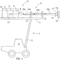
- FIG 1 shows schematically a significantly simplified side view of a rock drilling rig 1.
- the rock drilling rig 1 comprises a movable carrier 2 and a boom 3 at the end of which there is a feed beam 4 provided with a rock drilling machine 8 having a frame 8', an impact mechanism 5 and a rotating mechanism 6.
- the rock drilling rig 1 of Figure 1 further comprises a tool 9, the proximal end 9' of which is coupled to the rock drilling machine 8 and the distal end 9" of which is oriented towards the rock 12 to be drilled.
- the proximal end 9' of the tool 9 is shown in Figure 1 schematically by a broken line.
- the tool 9 of the rock drilling rig 1 of Figure 1 comprises drill rods 10a, 10b, 10c, 10d or drill stems 10a, 10b, 10c, 10d or drill tubes 10a, 10b, 10c, 10d, a drill shank 17 at the proximal end 9' of the tool 9 and a drill bit 11 at the distal end 9" of the tool 9.
- the drill bit 11 may be provided with buttons 11a, although other drill bit structures are also possible.
- the interconnected drill rods, drill stems or drill tubes form a drill string.
- the drill string, the drill shank 17 and the drill bit 11 form the tool 9 of the rock drilling machine 8, the drill rods, drill stems or drill tubes, the drill shank 17 and the drill bit 11 being parts of the tool 9.
- sectional drill rods also known as long hole drilling
- a number of drill rods depending on the depth of the hole to be drilled are attached between the drill bit 11 and the rock drilling machine 8.
- the tool 9 is assumed to comprise the drill rods 10a - 10d, the drill shank 17 and the drill bit 11, but depending on the actual implementation of the tool 9, the tool 9 may comprise the drill stems or the drill tubes instead of the drill rods.
- the rock drilling rig 1 of Figure 1 also comprises a feed mechanism 7, which is arranged to the feed beam 4, in relation to which the rock drilling machine 8 is movably arranged. During drilling the feed mechanism 7 is arranged to push the rock drilling machine 8 forward on the feed beam 4 and thus to push the drill bit 11 against the rock 12.
- Figure 1 shows the rock drilling rig 1 considerably smaller in relation to the structure of the rock drilling machine 8 than what it is in reality.
- the rock drilling rig 1 of Figure 1 has only one boom 3, feed beam 4, rock drilling machine 8 and feed mechanism 7, although it is obvious that a rock drilling rig may be provided with a plurality of booms 3 having a feed beam 4, a rock drilling machine 8 and a feed mechanism 7.
- the rock drilling machine 8 usually includes flushing means to prevent the drill bit 11 from being blocked.
- no flushing means are shown in Figure 1 .
- the drilling machine 8 may be hydraulically operated, but it may also be pneumatically or electrically operated.
- the drilling machine may also have a structure other than explained above.
- the impact mechanism is located in the drilling machine at the bottom of the drilling hole next to the drill bit, the drill bit being connected through the drill rods to the rotating mechanism located above the drilling hole.
- the impact mechanism 5 may be provided with an impact piston reciprocating under the influence of pressure medium and striking to the tool either directly or through an intermediate piece, such as a drill shank or another kind of adapter, between the tool 9 and the impact piston.
- an impact mechanism of a different structure is also possible.
- the operation of the impact mechanism 5 may thus also be based on use of electromagnetism or hydraulic pressure without any mechanically reciprocating impact piston and in this context the term impact mechanism refers also to impact mechanisms based on such characteristics.
- the stress wave generated by the impact mechanism 5 is delivered along the drill shank 17 and the drill rods 10a to 10d towards the drill bit 11 at the distal end 9" of the tool 9.
- the drill bit 11 and its buttons 11a strike the rock 12 to be drilled, thereby causing to the rock 12 a strong stress due to which cracks are formed in the rock 12.
- part of the stress wave exerted on or acting on the rock 12 reflects back to the tool 9 and along the tool 9 back towards the impact mechanism 5.
- the rotating mechanism 6 transmits continuous rotating force to the tool 9, thus causing the buttons 11a of the drill bit 11 to change their position after an impact and strike to a new spot on the rock 12 at the next impact.
- breaking hammers which provide another example of the rock breaking device
- an impact device such as an impact piston
- a non-rotating tool such as a chisel
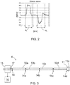
- Figure 2 shows schematically a stress wave, wherein the stress wave propagating towards the rock 12 to be drilled is denoted with a reference mark s i and the stress wave reflected from the rock 12 back to the tool 9 is denoted with a reference mark s r .
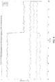
- FIG 3 shows schematically a side view of the tool 9 of the rock drilling machine 8 shown in Figure 1 .
- the tool 9 comprises the drill shank 17, drill rods 10a - 10d and the drill bit 11 connected to each other at joining points 14, 14a, 14b, 14c, 14d.
- the drill shank 17, the drill rods 10a - 10d and the drill bit 11 are typically connected to each other with threaded couplings but other joining solutions could also be used.
- the reflected stress wave is composed of components, i.e. reflected stress wave components, each reflected stress wave component being emerged or generated at a particular point in the tool.
- the typical points in the tool, wherein the reflected stress wave components are generated are discontinuities in the tool, such as the joining points 14, 14a, 14b, 14c, 14d in the tool 9 of Figure 3 , an end of the tool, such as an end surface of the drill bit 11 comprising the buttons 11a, as well as any point of a tool comprising a change of a cross-sectional area of the tool.
- any fractures possibly appearing in the tool, especially at the joining points of the parts of the tool provide also a respective reflected stress wave component.
- a condition of the tool of the rock breaking device may be monitored and possible control actions controlling the operation of the rock breaking device may be carried out on the basis of that monitoring.
- the reflected stress wave components of the stress wave in respect of the parts forming the tool 9 are identified by determining times of propagation of the reflected stress wave components, each reflected stress wave component emerging in response to a discontinuity in the tool, an end of the tool or a point of a change of a cross-sectional area in the tool, as said above.
- the determined time of the propagation of a specific reflected stress wave component associates or relates that specific reflected stress wave component to a specific point in the tool where the specific reflected stress wave component emerges in response to the properties of the tool at that point of the tool.
- At least one additional property of the respective reflected stress wave components is determined.
- the at least one additional property of the reflected stress wave component may be at least one of an energy of the reflected stress wave component, an attenuation of the reflected stress wave component, an amplitude of the reflected stress wave component, a shape of the reflected stress wave component and any interrelation thereof.
- the shape of the stress wave component may be determined for example by measuring a frequency content of the reflected stress wave component.
- a condition of the tool at the points where the reflected stress wave components emerge, or possible changes in the condition of the tool at the points where the reflected stress wave components emerge, may thereafter be determined or detected on the basis of the times of propagation of the reflected stress wave components and at least one additional property of the respective reflected stress wave components.
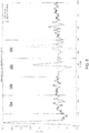
- Figure 4 discloses schematically graphs indicating energies of four reflected stress wave components RC1, RC2, RC3, RC4 emerged in a tool 9 like that of Figure 3 , i.e. in a tool composed of the drill shank 17, four successive drill rods 10a - 10d and a drill bit 11 at the distal end of the tool 9, in response to stress waves generated in the tool 9.
- the y-axis of Figure 4 presents energy amplitudes of the reflected stress wave components RC1 - RC4 and the x-axis presents time in seconds.
- the first reflected stress wave component RC1 indicates the reflected stress wave component emerged in response to the joining point 14a between the first drill rod 10a and the second drill rod 10b.
- the second reflected stress wave component RC2 indicates the reflected stress wave component emerged in response to the joining point 14b between the second drill rod 10b and the third drill rod 10c.
- the third reflected stress wave component RC3 indicates the reflected stress wave component emerged in response to the joining point 14c between the third drill rod 10c and the fourth drill rod 10d.
- the fourth reflected stress wave component RC4 indicates the reflected stress wave component emerged in response to the contact of the drill bit 11 against the rock 12. Any reflected stress wave component emerged in response to the drill shank 17 or in response to the joining point 14 between the drill shank 17 and the first drill rod 10a is ignored in Figure 4 , and also later in Figures 5 and 6 .
- reflected stress wave components there may exist also other measurable reflected stress wave components, such as reflected stress wave components originating for example from possible points of the tool comprising changes of the cross-sectional area of the tool. For the sake of clarity they are also neglected in this example because the energy levels of these reflected stress wave components are typically substantially small relative to the reflected stress wave components specifically mentioned above.
- the joining point 14d between the fourth drill rod 10d and the drill bit 11 may also generate a respective reflected stress wave component.
- the reflected stress wave component emerging in response to the fourth joining point 14d is included in the fourth reflected stress wave component RC4, which may take place in view of the stress wave measurement due to a very small distance between the end of the drill bit 11 facing to rock 12 and the fourth joining point 14d, unless very high sampling frequency is available for the measurement of the stress waves so that these two reflected stress wave components could also be distinguished from each other on the basis of the respective times of propagation.
- the energy of the fourth reflected stress wave component RC4 indicates the combined energy of the energies of the reflected stress wave components emerging in response to the contact of the drill bit 11 against the rock 12 and in response to the fourth joining point 14d between the fourth drill rod 10d and the drill bit 11.
- the reflected stress wave components may be measured by a measuring means 15 arranged in connection to the tool 9 or at an immediate vicinity of the tool 9.
- the operation of the measuring means 15 may for example be based on measuring changes in the magnetization of the tool 9 in response to the stress waves travelling in the tool 9.
- a variety of different suitable measuring means is known for a person skilled in the art of the rock breaking and a more detail configuration or an operation of these measuring means is not considered herein.
- the measured reflected stress wave components RC1 - RC4, i.e. measuring signals containing measurement information describing the measured reflected stress wave components RC1 - RC4, are forwarded from the measuring means 15 to at least one computing unit 16 configured to analyse the measured reflected stress wave components for monitoring the condition of the tool of the rock breaking device.
- the computing unit 16 is configured to identify reflected stress wave components of the stress wave in respect of the parts forming the tool by determining times of propagation of the reflected stress wave components, wherein, as said before, each reflected stress wave component emerges in response to the discontinuity in the tool, the end of the tool or the point of the change of the cross-sectional area in the tool.
- the computing unit 16 is configured to determine at least one additional property of the respective reflected stress wave components and determine the condition of the tool on the basis of the time of propagation of the at least one reflected stress wave component and at least one additional property of the same at least one reflected stress wave component.
- the at least one computing unit 16 may form a part of a control unit configured to control operations of the rock drilling device, such as the rock drilling machine 8, and/or the operations of the whole rock drilling rig 1.
- the at least one computing unit 16 may also be a unit separate from said control unit.
- the time period up to about 60 seconds relates to the normal operation of the rock drilling machine 8, the normal operation of the rock drilling machine 8 referring in this case to an operating situation of the rock drilling machine 8 wherein the tool 9 of the rock drilling machine 8 is undamaged.
- the energy amplitude of the fourth reflected stress wave component RC4 is typically the highest because it contains the energy of the stress wave component reflected from the rock 12 to be drilled back to the tool 9.
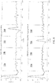
- Figure 5 shows schematically a graph as titled "Rod string OK" indicating amplitudes of the reflected stress wave components RC1 - RC4 in response to a single impact to the tool 9 during the normal operation situation of the rock drilling machine 8 with the undamaged tool, i.e. relating to the operation situation corresponding to the time period up to about 60 seconds in Figure 4 .
- the same graph is presented also in the upper part of Figure 6 .
- Figure 5 and 6 it is presented rodwise, i.e. for each rod 10a - 10d, calculation areas for the reflected stress wave components RC1 - RC4.
- the y-axis of Figures 5 , 6 presents an amplitude of the measurement and the x-axis presents a number of samples.
- Figures 5 and 6 show that the amplitude of the fourth reflected stress wave component RC4 is the highest because it contains the energy of the stress wave component reflected from the rock 12 to be drilled back to the tool 9.
- Figure 5 shows schematically a graph as titled "Upcoming rod break” indicating amplitudes of the reflected stress wave components RC1 - RC4 in response to the single impact to the tool 9 relating to the operation situation of the rock drilling machine 8 with the damaged tool, i.e. relating to the same operation situation as it is presented in Figure 4 after the time instant about 60 seconds.
- the same graph is presented also in the lower part of Figure 6 .
- Figures 5 and 6 show that the amplitude of the fourth reflected stress wave component RC4 decreases and the amplitude of the third reflected stress wave component RC3 increases when compared to the time period before said thread breakage because the thread breakage prevents the stress wave generated in the tool 9 to pass over the third joining point 14c in the same extent than before the thread breakage.
- the breakage of the male thread between two successive tool parts of the rock breaking device may be detected by the disclosed solution by monitoring the reflected stress wave components emerged in the tool.
- other conditions of the tool such as a breakage of a single part of the tool, such as a breakage of any drill rod 10a - 10d in the rock drilling machine 8 or a chisel in a breaking hammer, or a loose joint between successive tool parts, may be detected well before a total breakage of the tool, which could lead for example to a loss of at least a part of the tool 9 into a hole to be drilled.
- the solution disclosed thus enables monitoring a number of different conditions of the tools by monitoring a number of reflected stress wave components and a possible variations of properties thereof in respect of the parts forming the tool.
- the measurement of the reflected stress wave components has been interrupted at time instant about 100 seconds. At this time instant there has been a total breakage of the male thread at the third joining point 14c between the third drill rod 10c and the fourth drill rod 10d.
- This indicates that the solution disclosed herein is able to detect the breakage in the tool well before the total breakage of the tool, whereby it is possible to control the operation of the rock breaking device, such as to stop the operation of the rock breaking device, well before the total breakage of the tool.
- an upcoming tool break may be detected in response to an appearance of at least one new reflected stress wave component in the measured stress wave, i.e. at least one new reflected stress wave component having a time of propagation not appeared at a beginning of the measurement of the stress wave and having at least one additional property that is significant relative to the at least one additional property of the at least one reflected stress wave component being present at the beginning of the measurement of the stress wave.
- an upcoming tool break may be detected in response to a change in a level of the at least one additional property of the at least one reflected stress wave component when compared to a level of the at least one additional property at the beginning of the measurement of the stress wave.
- the level of the at least one additional property at the beginning of the measurement of the stress wave thus provides a reference level to which the level of the at least one additional property is compared during the measurement of the stress wave for detecting a possible upcoming tool break.
- Figure 4 provides an example of this kind of embodiment.
- an upcoming tool break may be detected in response to a change in a level of a ratio of at least one additional property of at least two reflected stress wave components when compared to a level of a ration of the at least one additional property of the at least two reflected stress wave components at the beginning of the measurement of the stress wave.
- the level of the ratio of the at least one additional property of the at least two reflected stress wave components at the beginning of the measurement of the stress wave thus provides a reference level to which the level of the ratio of the at least one additional property of the at least two reflected stress wave components is compared during the measurement of the stress wave for detecting a possible upcoming tool break.
- the computing unit is configured to monitor a variation of the at least one additional property of the reflected stress wave component time-wise and control the operation of the rock breaking device in response to a number of unexpected changes appearing in the at least one additional property of the reflected stress wave component.
- the changes appearing in the at least one additional property of the reflected stress wave component is monitored and if there is any unexpected change in the property to be monitored, typically abrupt change but possibly also a long-term change, the computing unit may effect on the operation of the rock breaking device, either directly or through the aforementioned control unit dedicated for the rock breaking device, for controlling the operation of the rock breaking device, such as to stop the operation of the rock breaking device.
- the unexpected change refers to a change which is not expected to happen during a normal operation of the rock breaking device, for example due to a normal wear of the tool.
- the abrupt changes like that disclosed in Figure 4 , but possibly also the long-term changes, may for example also be detected by comparing values describing the at least one additional property of the reflected stress wave component to a limit value set for that additional property.
- the limit value may for example be determined on the basis of the values of that additional property during a beginning of the normal operation situation of the rock breaking device.
- the computing unit is configured to compute substantially continuously values of the at least one additional property of the reflected stress wave component, compare at least one latest value of the additional property to at least one previous value of the same additional property, and determine the condition of the tool on the basis of said comparison.
- the at least one latest determined value of the additional property is compared to at least one previous value of the same additional property, and if there is a significant difference, for example in per cents more than five, ten or twenty per cents, between the at least one latest value and the at least one previous value, it may be assumed that there is a breakage in the tool.
- the computing unit is configured to compute substantially continuously values of the at least one additional property of the reflected stress wave component, compare a first value determined on the basis of at least one latest value of the additional property to a second value determined on the basis of at least one previous value of the same additional property, and determine the condition of the tool on the basis of said comparison.
- This embodiment is substantially similar to the embodiment of previous paragraph but in this embodiment it is inspected auxiliary values determined on the basis of the values describing the additional property and not the values describing the additional property as such.
- the computing unit is configured to control at least one operating parameter of the rock breaking device in response to a number of unexpected changes in the at least one additional property of the reflected stress wave component. This means for example that in some cases only one single significant change in the value of the at least one additional property may cause the computing unit to control the operation of the rock breaking device, but in some cases it may take few or several minor changes in the value of the at least one additional property before any control action by the computing unit is provided.
- the computing unit is configured to control the rock breaking device to stop the operation in response to a number of unexpected changes in the at least one additional property of the reflected stress wave component.
- the monitoring of the condition of the tool disclosed herein may be applied in other rock breaking devices employing impact pulses, such as breaking hammers or other breaking devices intended for breaking rock material or another hard material.
Landscapes
- Engineering & Computer Science (AREA)
- Mining & Mineral Resources (AREA)
- Life Sciences & Earth Sciences (AREA)
- Physics & Mathematics (AREA)
- Geology (AREA)
- General Life Sciences & Earth Sciences (AREA)
- Geochemistry & Mineralogy (AREA)
- Environmental & Geological Engineering (AREA)
- Fluid Mechanics (AREA)
- General Physics & Mathematics (AREA)
- Acoustics & Sound (AREA)
- Health & Medical Sciences (AREA)
- Mechanical Engineering (AREA)
- Geophysics (AREA)
- Chemical & Material Sciences (AREA)
- General Health & Medical Sciences (AREA)
- Biochemistry (AREA)
- Immunology (AREA)
- Pathology (AREA)
- Toxicology (AREA)
- Analytical Chemistry (AREA)
- Earth Drilling (AREA)
- Soil Sciences (AREA)
- Testing Or Calibration Of Command Recording Devices (AREA)
Priority Applications (9)
| Application Number | Priority Date | Filing Date | Title |
|---|---|---|---|
| EP18192024.0A EP3617441B1 (fr) | 2018-08-31 | 2018-08-31 | Dispositif brise-roches |
| AU2019204742A AU2019204742B2 (en) | 2018-08-31 | 2019-07-02 | Rock breaking device |
| CA3049337A CA3049337A1 (fr) | 2018-08-31 | 2019-07-11 | Appareil d`abattage de la roche |
| ZA2019/04686A ZA201904686B (en) | 2018-08-31 | 2019-07-17 | Rock breaking device |
| KR1020190094240A KR102701925B1 (ko) | 2018-08-31 | 2019-08-02 | 암석 파쇄 디바이스 |
| CN201910720504.3A CN110924924A (zh) | 2018-08-31 | 2019-08-06 | 岩石破碎装置 |
| CL2019002341A CL2019002341A1 (es) | 2018-08-31 | 2019-08-19 | Dispositivo rompedor de roca. |
| US16/544,863 US11085286B2 (en) | 2018-08-31 | 2019-08-19 | Rock breaking device |
| JP2019149579A JP7305482B2 (ja) | 2018-08-31 | 2019-08-19 | 岩石破砕装置 |
Applications Claiming Priority (1)
| Application Number | Priority Date | Filing Date | Title |
|---|---|---|---|
| EP18192024.0A EP3617441B1 (fr) | 2018-08-31 | 2018-08-31 | Dispositif brise-roches |
Publications (2)
| Publication Number | Publication Date |
|---|---|
| EP3617441A1 true EP3617441A1 (fr) | 2020-03-04 |
| EP3617441B1 EP3617441B1 (fr) | 2021-06-09 |
Family
ID=63452558
Family Applications (1)
| Application Number | Title | Priority Date | Filing Date |
|---|---|---|---|
| EP18192024.0A Active EP3617441B1 (fr) | 2018-08-31 | 2018-08-31 | Dispositif brise-roches |
Country Status (9)
| Country | Link |
|---|---|
| US (1) | US11085286B2 (fr) |
| EP (1) | EP3617441B1 (fr) |
| JP (1) | JP7305482B2 (fr) |
| KR (1) | KR102701925B1 (fr) |
| CN (1) | CN110924924A (fr) |
| AU (1) | AU2019204742B2 (fr) |
| CA (1) | CA3049337A1 (fr) |
| CL (1) | CL2019002341A1 (fr) |
| ZA (1) | ZA201904686B (fr) |
Cited By (1)
| Publication number | Priority date | Publication date | Assignee | Title |
|---|---|---|---|---|
| US20220268103A1 (en) * | 2019-07-05 | 2022-08-25 | Epiroc Rock Drills Aktiebolag | Method and system for estimating wear of a drill bit |
Families Citing this family (6)
| Publication number | Priority date | Publication date | Assignee | Title |
|---|---|---|---|---|
| EP3617442B1 (fr) | 2018-08-31 | 2022-10-19 | Sandvik Mining and Construction Oy | Dispositif de forage de roche |
| EP3617441B1 (fr) * | 2018-08-31 | 2021-06-09 | Sandvik Mining and Construction Oy | Dispositif brise-roches |
| CN111852402B (zh) * | 2020-08-31 | 2022-04-29 | 四川轻化工大学 | 一种破碎大尺寸井下落物的井口工具 |
| CN112412345B (zh) * | 2020-10-28 | 2022-09-13 | 西华大学 | 隧道开挖排险装置 |
| EP4264001B1 (fr) * | 2020-12-21 | 2024-09-25 | Epiroc Rock Drills Aktiebolag | Procédé et système pour la détection de l'état d'un joint d'un train de tiges de forage |
| CN113622899B (zh) * | 2021-08-11 | 2023-06-27 | 中国石油大学(华东) | 一种钻井液连续波信号调制系统及方法 |
Citations (6)
| Publication number | Priority date | Publication date | Assignee | Title |
|---|---|---|---|---|
| US4671366A (en) | 1984-06-12 | 1987-06-09 | Oy Tampella Ab | Method for optimizing rock drilling |
| EP0409304A1 (fr) * | 1989-07-19 | 1991-01-23 | Services Petroliers Schlumberger | Méthode pour la surveillance de forage d'un sondage |
| WO2003033216A1 (fr) * | 2001-10-18 | 2003-04-24 | Sandvik Tamrock Oy | Procede et appareil de surveillance du fonctionnement d'un dispositif de percussion |
| WO2007082997A1 (fr) * | 2006-01-17 | 2007-07-26 | Sandvik Mining And Construction Oy | Dispositif de mesure, dispositif brise-roches et procede de mesure d’une onde de contrainte |
| WO2010037905A1 (fr) * | 2008-09-30 | 2010-04-08 | Sandvik Mining And Construction Oy | Procédé et agencement dans une installation de forage de roche |
| EP2416149A1 (fr) * | 2009-03-31 | 2012-02-08 | Sumitomo Metal Industries, Ltd. | Procédé pour évaluer l'état de raccordement d'un raccord fileté de tuyauterie, procédé pour le raccordement d'un raccord fileté de tuyauterie, et dispositif pour évaluer l'état de raccordement d'un raccord fileté de tuyauterie |
Family Cites Families (11)
| Publication number | Priority date | Publication date | Assignee | Title |
|---|---|---|---|---|
| US4759412A (en) * | 1986-10-20 | 1988-07-26 | Brazell Ii James W | Rock breaking device |
| US6480118B1 (en) * | 2000-03-27 | 2002-11-12 | Halliburton Energy Services, Inc. | Method of drilling in response to looking ahead of drill bit |
| FI116968B (fi) * | 2004-07-02 | 2006-04-28 | Sandvik Tamrock Oy | Menetelmä iskulaitteen ohjaamiseksi, ohjelmistotuote sekä iskulaite |
| DE102010041238A1 (de) * | 2009-12-30 | 2011-07-07 | Robert Bosch GmbH, 70469 | Gesteinsbohrwerkzeug zur dreh-schlagenden Bearbeitung von Beton, Gestein, Mauerwerk und dergleichen Materialien |
| US9400239B2 (en) * | 2012-07-30 | 2016-07-26 | North Carolina State University | Methods, systems, and computer readable media for testing cutting blade integrity |
| WO2014206471A1 (fr) * | 2013-06-27 | 2014-12-31 | Sandvik Mining And Construction Oy | Agencement de commande de processus de forage par percussion |
| PL2845989T3 (pl) * | 2013-09-09 | 2016-05-31 | Sandvik Intellectual Property | Modyfikacja fali udarowej w aparacie do wiercenia udarowego i sposób |
| WO2017147563A1 (fr) * | 2016-02-26 | 2017-08-31 | Beaton Curtis L | Procédé et appareil servant à fendre ou cliver la roche |
| EP3617442B1 (fr) * | 2018-08-31 | 2022-10-19 | Sandvik Mining and Construction Oy | Dispositif de forage de roche |
| EP3617441B1 (fr) * | 2018-08-31 | 2021-06-09 | Sandvik Mining and Construction Oy | Dispositif brise-roches |
| EP3670831B1 (fr) * | 2018-12-21 | 2023-02-15 | Sandvik Mining and Construction Oy | Machine de forage de roches, appareil de forage de roches et procédé de mesure |
-
2018
- 2018-08-31 EP EP18192024.0A patent/EP3617441B1/fr active Active
-
2019
- 2019-07-02 AU AU2019204742A patent/AU2019204742B2/en active Active
- 2019-07-11 CA CA3049337A patent/CA3049337A1/fr active Pending
- 2019-07-17 ZA ZA2019/04686A patent/ZA201904686B/en unknown
- 2019-08-02 KR KR1020190094240A patent/KR102701925B1/ko active Active
- 2019-08-06 CN CN201910720504.3A patent/CN110924924A/zh active Pending
- 2019-08-19 CL CL2019002341A patent/CL2019002341A1/es unknown
- 2019-08-19 US US16/544,863 patent/US11085286B2/en active Active
- 2019-08-19 JP JP2019149579A patent/JP7305482B2/ja active Active
Patent Citations (6)
| Publication number | Priority date | Publication date | Assignee | Title |
|---|---|---|---|---|
| US4671366A (en) | 1984-06-12 | 1987-06-09 | Oy Tampella Ab | Method for optimizing rock drilling |
| EP0409304A1 (fr) * | 1989-07-19 | 1991-01-23 | Services Petroliers Schlumberger | Méthode pour la surveillance de forage d'un sondage |
| WO2003033216A1 (fr) * | 2001-10-18 | 2003-04-24 | Sandvik Tamrock Oy | Procede et appareil de surveillance du fonctionnement d'un dispositif de percussion |
| WO2007082997A1 (fr) * | 2006-01-17 | 2007-07-26 | Sandvik Mining And Construction Oy | Dispositif de mesure, dispositif brise-roches et procede de mesure d’une onde de contrainte |
| WO2010037905A1 (fr) * | 2008-09-30 | 2010-04-08 | Sandvik Mining And Construction Oy | Procédé et agencement dans une installation de forage de roche |
| EP2416149A1 (fr) * | 2009-03-31 | 2012-02-08 | Sumitomo Metal Industries, Ltd. | Procédé pour évaluer l'état de raccordement d'un raccord fileté de tuyauterie, procédé pour le raccordement d'un raccord fileté de tuyauterie, et dispositif pour évaluer l'état de raccordement d'un raccord fileté de tuyauterie |
Cited By (3)
| Publication number | Priority date | Publication date | Assignee | Title |
|---|---|---|---|---|
| US20220268103A1 (en) * | 2019-07-05 | 2022-08-25 | Epiroc Rock Drills Aktiebolag | Method and system for estimating wear of a drill bit |
| US12006770B2 (en) * | 2019-07-05 | 2024-06-11 | Epiroc Rock Drills Aktiebolag | Method and system for estimating wear of a drill bit |
| AU2020310048B2 (en) * | 2019-07-05 | 2025-10-30 | Epiroc Rock Drills Aktiebolag | Method and system for estimating wear of a drill bit |
Also Published As
| Publication number | Publication date |
|---|---|
| CA3049337A1 (fr) | 2020-02-29 |
| JP7305482B2 (ja) | 2023-07-10 |
| ZA201904686B (en) | 2022-11-30 |
| KR20200026696A (ko) | 2020-03-11 |
| JP2020076290A (ja) | 2020-05-21 |
| EP3617441B1 (fr) | 2021-06-09 |
| AU2019204742B2 (en) | 2025-04-17 |
| US11085286B2 (en) | 2021-08-10 |
| KR102701925B1 (ko) | 2024-09-02 |
| AU2019204742A1 (en) | 2020-03-19 |
| US20200080411A1 (en) | 2020-03-12 |
| CL2019002341A1 (es) | 2020-01-17 |
| CN110924924A (zh) | 2020-03-27 |
Similar Documents
| Publication | Publication Date | Title |
|---|---|---|
| EP3617441B1 (fr) | Dispositif brise-roches | |
| US11002127B2 (en) | Rock drilling device | |
| AU2009299713B2 (en) | Method and arrangement in rock drilling rig | |
| EP4264001B1 (fr) | Procédé et système pour la détection de l'état d'un joint d'un train de tiges de forage | |
| KR102865827B1 (ko) | 굴착 기계 및 굴착 기계의 굴착 공정 제어 방법 | |
| CN116547441B (zh) | 用于检测钻柱的接头的状态的方法和系统 |
Legal Events
| Date | Code | Title | Description |
|---|---|---|---|
| PUAI | Public reference made under article 153(3) epc to a published international application that has entered the european phase |
Free format text: ORIGINAL CODE: 0009012 |
|
| STAA | Information on the status of an ep patent application or granted ep patent |
Free format text: STATUS: THE APPLICATION HAS BEEN PUBLISHED |
|
| AK | Designated contracting states |
Kind code of ref document: A1 Designated state(s): AL AT BE BG CH CY CZ DE DK EE ES FI FR GB GR HR HU IE IS IT LI LT LU LV MC MK MT NL NO PL PT RO RS SE SI SK SM TR |
|
| AX | Request for extension of the european patent |
Extension state: BA ME |
|
| STAA | Information on the status of an ep patent application or granted ep patent |
Free format text: STATUS: REQUEST FOR EXAMINATION WAS MADE |
|
| 17P | Request for examination filed |
Effective date: 20200904 |
|
| RBV | Designated contracting states (corrected) |
Designated state(s): AL AT BE BG CH CY CZ DE DK EE ES FI FR GB GR HR HU IE IS IT LI LT LU LV MC MK MT NL NO PL PT RO RS SE SI SK SM TR |
|
| GRAP | Despatch of communication of intention to grant a patent |
Free format text: ORIGINAL CODE: EPIDOSNIGR1 |
|
| STAA | Information on the status of an ep patent application or granted ep patent |
Free format text: STATUS: GRANT OF PATENT IS INTENDED |
|
| RIC1 | Information provided on ipc code assigned before grant |
Ipc: E21B 44/00 20060101AFI20210215BHEP Ipc: E21B 47/00 20120101ALI20210215BHEP |
|
| INTG | Intention to grant announced |
Effective date: 20210311 |
|
| GRAS | Grant fee paid |
Free format text: ORIGINAL CODE: EPIDOSNIGR3 |
|
| GRAA | (expected) grant |
Free format text: ORIGINAL CODE: 0009210 |
|
| STAA | Information on the status of an ep patent application or granted ep patent |
Free format text: STATUS: THE PATENT HAS BEEN GRANTED |
|
| AK | Designated contracting states |
Kind code of ref document: B1 Designated state(s): AL AT BE BG CH CY CZ DE DK EE ES FI FR GB GR HR HU IE IS IT LI LT LU LV MC MK MT NL NO PL PT RO RS SE SI SK SM TR |
|
| REG | Reference to a national code |
Ref country code: GB Ref legal event code: FG4D |
|
| REG | Reference to a national code |
Ref country code: CH Ref legal event code: EP Ref country code: AT Ref legal event code: REF Ref document number: 1400666 Country of ref document: AT Kind code of ref document: T Effective date: 20210615 |
|
| REG | Reference to a national code |
Ref country code: DE Ref legal event code: R096 Ref document number: 602018018279 Country of ref document: DE |
|
| REG | Reference to a national code |
Ref country code: FI Ref legal event code: FGE |
|
| REG | Reference to a national code |
Ref country code: IE Ref legal event code: FG4D |
|
| REG | Reference to a national code |
Ref country code: SE Ref legal event code: TRGR |
|
| REG | Reference to a national code |
Ref country code: LT Ref legal event code: MG9D |
|
| PG25 | Lapsed in a contracting state [announced via postgrant information from national office to epo] |
Ref country code: HR Free format text: LAPSE BECAUSE OF FAILURE TO SUBMIT A TRANSLATION OF THE DESCRIPTION OR TO PAY THE FEE WITHIN THE PRESCRIBED TIME-LIMIT Effective date: 20210609 Ref country code: LT Free format text: LAPSE BECAUSE OF FAILURE TO SUBMIT A TRANSLATION OF THE DESCRIPTION OR TO PAY THE FEE WITHIN THE PRESCRIBED TIME-LIMIT Effective date: 20210609 Ref country code: BG Free format text: LAPSE BECAUSE OF FAILURE TO SUBMIT A TRANSLATION OF THE DESCRIPTION OR TO PAY THE FEE WITHIN THE PRESCRIBED TIME-LIMIT Effective date: 20210909 |
|
| REG | Reference to a national code |
Ref country code: AT Ref legal event code: MK05 Ref document number: 1400666 Country of ref document: AT Kind code of ref document: T Effective date: 20210609 |
|
| REG | Reference to a national code |
Ref country code: NL Ref legal event code: MP Effective date: 20210609 |
|
| PG25 | Lapsed in a contracting state [announced via postgrant information from national office to epo] |
Ref country code: GR Free format text: LAPSE BECAUSE OF FAILURE TO SUBMIT A TRANSLATION OF THE DESCRIPTION OR TO PAY THE FEE WITHIN THE PRESCRIBED TIME-LIMIT Effective date: 20210910 Ref country code: NO Free format text: LAPSE BECAUSE OF FAILURE TO SUBMIT A TRANSLATION OF THE DESCRIPTION OR TO PAY THE FEE WITHIN THE PRESCRIBED TIME-LIMIT Effective date: 20210909 Ref country code: LV Free format text: LAPSE BECAUSE OF FAILURE TO SUBMIT A TRANSLATION OF THE DESCRIPTION OR TO PAY THE FEE WITHIN THE PRESCRIBED TIME-LIMIT Effective date: 20210609 Ref country code: RS Free format text: LAPSE BECAUSE OF FAILURE TO SUBMIT A TRANSLATION OF THE DESCRIPTION OR TO PAY THE FEE WITHIN THE PRESCRIBED TIME-LIMIT Effective date: 20210609 |
|
| PG25 | Lapsed in a contracting state [announced via postgrant information from national office to epo] |
Ref country code: SM Free format text: LAPSE BECAUSE OF FAILURE TO SUBMIT A TRANSLATION OF THE DESCRIPTION OR TO PAY THE FEE WITHIN THE PRESCRIBED TIME-LIMIT Effective date: 20210609 Ref country code: SK Free format text: LAPSE BECAUSE OF FAILURE TO SUBMIT A TRANSLATION OF THE DESCRIPTION OR TO PAY THE FEE WITHIN THE PRESCRIBED TIME-LIMIT Effective date: 20210609 Ref country code: EE Free format text: LAPSE BECAUSE OF FAILURE TO SUBMIT A TRANSLATION OF THE DESCRIPTION OR TO PAY THE FEE WITHIN THE PRESCRIBED TIME-LIMIT Effective date: 20210609 Ref country code: ES Free format text: LAPSE BECAUSE OF FAILURE TO SUBMIT A TRANSLATION OF THE DESCRIPTION OR TO PAY THE FEE WITHIN THE PRESCRIBED TIME-LIMIT Effective date: 20210609 Ref country code: NL Free format text: LAPSE BECAUSE OF FAILURE TO SUBMIT A TRANSLATION OF THE DESCRIPTION OR TO PAY THE FEE WITHIN THE PRESCRIBED TIME-LIMIT Effective date: 20210609 Ref country code: PT Free format text: LAPSE BECAUSE OF FAILURE TO SUBMIT A TRANSLATION OF THE DESCRIPTION OR TO PAY THE FEE WITHIN THE PRESCRIBED TIME-LIMIT Effective date: 20211011 Ref country code: RO Free format text: LAPSE BECAUSE OF FAILURE TO SUBMIT A TRANSLATION OF THE DESCRIPTION OR TO PAY THE FEE WITHIN THE PRESCRIBED TIME-LIMIT Effective date: 20210609 Ref country code: CZ Free format text: LAPSE BECAUSE OF FAILURE TO SUBMIT A TRANSLATION OF THE DESCRIPTION OR TO PAY THE FEE WITHIN THE PRESCRIBED TIME-LIMIT Effective date: 20210609 Ref country code: AT Free format text: LAPSE BECAUSE OF FAILURE TO SUBMIT A TRANSLATION OF THE DESCRIPTION OR TO PAY THE FEE WITHIN THE PRESCRIBED TIME-LIMIT Effective date: 20210609 |
|
| PG25 | Lapsed in a contracting state [announced via postgrant information from national office to epo] |
Ref country code: PL Free format text: LAPSE BECAUSE OF FAILURE TO SUBMIT A TRANSLATION OF THE DESCRIPTION OR TO PAY THE FEE WITHIN THE PRESCRIBED TIME-LIMIT Effective date: 20210609 |
|
| REG | Reference to a national code |
Ref country code: DE Ref legal event code: R097 Ref document number: 602018018279 Country of ref document: DE |
|
| REG | Reference to a national code |
Ref country code: CH Ref legal event code: PL |
|
| PG25 | Lapsed in a contracting state [announced via postgrant information from national office to epo] |
Ref country code: MC Free format text: LAPSE BECAUSE OF FAILURE TO SUBMIT A TRANSLATION OF THE DESCRIPTION OR TO PAY THE FEE WITHIN THE PRESCRIBED TIME-LIMIT Effective date: 20210609 |
|
| PLBE | No opposition filed within time limit |
Free format text: ORIGINAL CODE: 0009261 |
|
| STAA | Information on the status of an ep patent application or granted ep patent |
Free format text: STATUS: NO OPPOSITION FILED WITHIN TIME LIMIT |
|
| REG | Reference to a national code |
Ref country code: BE Ref legal event code: MM Effective date: 20210831 |
|
| PG25 | Lapsed in a contracting state [announced via postgrant information from national office to epo] |
Ref country code: LI Free format text: LAPSE BECAUSE OF NON-PAYMENT OF DUE FEES Effective date: 20210831 Ref country code: DK Free format text: LAPSE BECAUSE OF FAILURE TO SUBMIT A TRANSLATION OF THE DESCRIPTION OR TO PAY THE FEE WITHIN THE PRESCRIBED TIME-LIMIT Effective date: 20210609 Ref country code: CH Free format text: LAPSE BECAUSE OF NON-PAYMENT OF DUE FEES Effective date: 20210831 |
|
| 26N | No opposition filed |
Effective date: 20220310 |
|
| PG25 | Lapsed in a contracting state [announced via postgrant information from national office to epo] |
Ref country code: LU Free format text: LAPSE BECAUSE OF NON-PAYMENT OF DUE FEES Effective date: 20210831 Ref country code: AL Free format text: LAPSE BECAUSE OF FAILURE TO SUBMIT A TRANSLATION OF THE DESCRIPTION OR TO PAY THE FEE WITHIN THE PRESCRIBED TIME-LIMIT Effective date: 20210609 |
|
| PG25 | Lapsed in a contracting state [announced via postgrant information from national office to epo] |
Ref country code: IT Free format text: LAPSE BECAUSE OF FAILURE TO SUBMIT A TRANSLATION OF THE DESCRIPTION OR TO PAY THE FEE WITHIN THE PRESCRIBED TIME-LIMIT Effective date: 20210609 Ref country code: BE Free format text: LAPSE BECAUSE OF NON-PAYMENT OF DUE FEES Effective date: 20210831 |
|
| GBPC | Gb: european patent ceased through non-payment of renewal fee |
Effective date: 20220831 |
|
| PG25 | Lapsed in a contracting state [announced via postgrant information from national office to epo] |
Ref country code: CY Free format text: LAPSE BECAUSE OF FAILURE TO SUBMIT A TRANSLATION OF THE DESCRIPTION OR TO PAY THE FEE WITHIN THE PRESCRIBED TIME-LIMIT Effective date: 20210609 |
|
| P01 | Opt-out of the competence of the unified patent court (upc) registered |
Effective date: 20230603 |
|
| PG25 | Lapsed in a contracting state [announced via postgrant information from national office to epo] |
Ref country code: HU Free format text: LAPSE BECAUSE OF FAILURE TO SUBMIT A TRANSLATION OF THE DESCRIPTION OR TO PAY THE FEE WITHIN THE PRESCRIBED TIME-LIMIT; INVALID AB INITIO Effective date: 20180831 |
|
| PG25 | Lapsed in a contracting state [announced via postgrant information from national office to epo] |
Ref country code: GB Free format text: LAPSE BECAUSE OF NON-PAYMENT OF DUE FEES Effective date: 20220831 |
|
| PG25 | Lapsed in a contracting state [announced via postgrant information from national office to epo] |
Ref country code: MK Free format text: LAPSE BECAUSE OF FAILURE TO SUBMIT A TRANSLATION OF THE DESCRIPTION OR TO PAY THE FEE WITHIN THE PRESCRIBED TIME-LIMIT Effective date: 20210609 |
|
| PG25 | Lapsed in a contracting state [announced via postgrant information from national office to epo] |
Ref country code: MT Free format text: LAPSE BECAUSE OF FAILURE TO SUBMIT A TRANSLATION OF THE DESCRIPTION OR TO PAY THE FEE WITHIN THE PRESCRIBED TIME-LIMIT Effective date: 20210609 |
|
| PGFP | Annual fee paid to national office [announced via postgrant information from national office to epo] |
Ref country code: FI Payment date: 20250814 Year of fee payment: 8 |
|
| PGFP | Annual fee paid to national office [announced via postgrant information from national office to epo] |
Ref country code: DE Payment date: 20250702 Year of fee payment: 8 |
|
| PGFP | Annual fee paid to national office [announced via postgrant information from national office to epo] |
Ref country code: TR Payment date: 20250829 Year of fee payment: 8 |
|
| PGFP | Annual fee paid to national office [announced via postgrant information from national office to epo] |
Ref country code: FR Payment date: 20250721 Year of fee payment: 8 |
|
| PGFP | Annual fee paid to national office [announced via postgrant information from national office to epo] |
Ref country code: SE Payment date: 20250702 Year of fee payment: 8 |
|
| PGFP | Annual fee paid to national office [announced via postgrant information from national office to epo] |
Ref country code: IE Payment date: 20250702 Year of fee payment: 8 |