EP3617465A1 - Vorrichtung zur behandlung von abgas aus einem motor und verfahren zur herstellung der vorrichtung - Google Patents
Vorrichtung zur behandlung von abgas aus einem motor und verfahren zur herstellung der vorrichtung Download PDFInfo
- Publication number
- EP3617465A1 EP3617465A1 EP18814241.8A EP18814241A EP3617465A1 EP 3617465 A1 EP3617465 A1 EP 3617465A1 EP 18814241 A EP18814241 A EP 18814241A EP 3617465 A1 EP3617465 A1 EP 3617465A1
- Authority
- EP
- European Patent Office
- Prior art keywords
- catalyst
- filter
- exhaust gas
- pores
- supported
- Prior art date
- Legal status (The legal status is an assumption and is not a legal conclusion. Google has not performed a legal analysis and makes no representation as to the accuracy of the status listed.)
- Granted
Links
Images


Classifications
-
- F—MECHANICAL ENGINEERING; LIGHTING; HEATING; WEAPONS; BLASTING
- F01—MACHINES OR ENGINES IN GENERAL; ENGINE PLANTS IN GENERAL; STEAM ENGINES
- F01N—GAS-FLOW SILENCERS OR EXHAUST APPARATUS FOR MACHINES OR ENGINES IN GENERAL; GAS-FLOW SILENCERS OR EXHAUST APPARATUS FOR INTERNAL-COMBUSTION ENGINES
- F01N3/00—Exhaust or silencing apparatus having means for purifying, rendering innocuous, or otherwise treating exhaust
- F01N3/02—Exhaust or silencing apparatus having means for purifying, rendering innocuous, or otherwise treating exhaust for cooling, or for removing solid constituents of, exhaust
- F01N3/021—Exhaust or silencing apparatus having means for purifying, rendering innocuous, or otherwise treating exhaust for cooling, or for removing solid constituents of, exhaust by means of filters
- F01N3/033—Exhaust or silencing apparatus having means for purifying, rendering innocuous, or otherwise treating exhaust for cooling, or for removing solid constituents of, exhaust by means of filters in combination with other devices
- F01N3/035—Exhaust or silencing apparatus having means for purifying, rendering innocuous, or otherwise treating exhaust for cooling, or for removing solid constituents of, exhaust by means of filters in combination with other devices with catalytic reactors
-
- B—PERFORMING OPERATIONS; TRANSPORTING
- B01—PHYSICAL OR CHEMICAL PROCESSES OR APPARATUS IN GENERAL
- B01D—SEPARATION
- B01D53/00—Separation of gases or vapours; Recovering vapours of volatile solvents from gases; Chemical or biological purification of waste gases, e.g. engine exhaust gases, smoke, fumes, flue gases, aerosols
- B01D53/34—Chemical or biological purification of waste gases
- B01D53/92—Chemical or biological purification of waste gases of engine exhaust gases
- B01D53/94—Chemical or biological purification of waste gases of engine exhaust gases by catalytic processes
- B01D53/944—Simultaneously removing carbon monoxide, hydrocarbons or carbon making use of oxidation catalysts
-
- B—PERFORMING OPERATIONS; TRANSPORTING
- B01—PHYSICAL OR CHEMICAL PROCESSES OR APPARATUS IN GENERAL
- B01D—SEPARATION
- B01D39/00—Filtering material for liquid or gaseous fluids
- B01D39/14—Other self-supporting filtering material ; Other filtering material
- B01D39/20—Other self-supporting filtering material ; Other filtering material of inorganic material, e.g. asbestos paper, metallic filtering material of non-woven wires
-
- B—PERFORMING OPERATIONS; TRANSPORTING
- B01—PHYSICAL OR CHEMICAL PROCESSES OR APPARATUS IN GENERAL
- B01D—SEPARATION
- B01D46/00—Filters or filtering processes specially modified for separating dispersed particles from gases or vapours
-
- B—PERFORMING OPERATIONS; TRANSPORTING
- B01—PHYSICAL OR CHEMICAL PROCESSES OR APPARATUS IN GENERAL
- B01D—SEPARATION
- B01D46/00—Filters or filtering processes specially modified for separating dispersed particles from gases or vapours
- B01D46/24—Particle separators, e.g. dust precipitators, using rigid hollow filter bodies
- B01D46/2403—Particle separators, e.g. dust precipitators, using rigid hollow filter bodies characterised by the physical shape or structure of the filtering element
- B01D46/2418—Honeycomb filters
-
- B—PERFORMING OPERATIONS; TRANSPORTING
- B01—PHYSICAL OR CHEMICAL PROCESSES OR APPARATUS IN GENERAL
- B01D—SEPARATION
- B01D53/00—Separation of gases or vapours; Recovering vapours of volatile solvents from gases; Chemical or biological purification of waste gases, e.g. engine exhaust gases, smoke, fumes, flue gases, aerosols
- B01D53/34—Chemical or biological purification of waste gases
- B01D53/92—Chemical or biological purification of waste gases of engine exhaust gases
- B01D53/94—Chemical or biological purification of waste gases of engine exhaust gases by catalytic processes
-
- B—PERFORMING OPERATIONS; TRANSPORTING
- B01—PHYSICAL OR CHEMICAL PROCESSES OR APPARATUS IN GENERAL
- B01J—CHEMICAL OR PHYSICAL PROCESSES, e.g. CATALYSIS OR COLLOID CHEMISTRY; THEIR RELEVANT APPARATUS
- B01J23/00—Catalysts comprising metals or metal oxides or hydroxides, not provided for in group B01J21/00
- B01J23/38—Catalysts comprising metals or metal oxides or hydroxides, not provided for in group B01J21/00 of noble metals
- B01J23/54—Catalysts comprising metals or metal oxides or hydroxides, not provided for in group B01J21/00 of noble metals combined with metals, oxides or hydroxides provided for in groups B01J23/02 - B01J23/36
- B01J23/56—Platinum group metals
- B01J23/63—Platinum group metals with rare earths or actinides
-
- B—PERFORMING OPERATIONS; TRANSPORTING
- B01—PHYSICAL OR CHEMICAL PROCESSES OR APPARATUS IN GENERAL
- B01J—CHEMICAL OR PHYSICAL PROCESSES, e.g. CATALYSIS OR COLLOID CHEMISTRY; THEIR RELEVANT APPARATUS
- B01J37/00—Processes, in general, for preparing catalysts; Processes, in general, for activation of catalysts
- B01J37/02—Impregnation, coating or precipitation
- B01J37/0215—Coating
- B01J37/0228—Coating in several steps
-
- B—PERFORMING OPERATIONS; TRANSPORTING
- B01—PHYSICAL OR CHEMICAL PROCESSES OR APPARATUS IN GENERAL
- B01J—CHEMICAL OR PHYSICAL PROCESSES, e.g. CATALYSIS OR COLLOID CHEMISTRY; THEIR RELEVANT APPARATUS
- B01J37/00—Processes, in general, for preparing catalysts; Processes, in general, for activation of catalysts
- B01J37/02—Impregnation, coating or precipitation
- B01J37/0236—Drying, e.g. preparing a suspension, adding a soluble salt and drying
-
- B—PERFORMING OPERATIONS; TRANSPORTING
- B01—PHYSICAL OR CHEMICAL PROCESSES OR APPARATUS IN GENERAL
- B01J—CHEMICAL OR PHYSICAL PROCESSES, e.g. CATALYSIS OR COLLOID CHEMISTRY; THEIR RELEVANT APPARATUS
- B01J37/00—Processes, in general, for preparing catalysts; Processes, in general, for activation of catalysts
- B01J37/02—Impregnation, coating or precipitation
- B01J37/024—Multiple impregnation or coating
- B01J37/0244—Coatings comprising several layers
-
- B—PERFORMING OPERATIONS; TRANSPORTING
- B01—PHYSICAL OR CHEMICAL PROCESSES OR APPARATUS IN GENERAL
- B01J—CHEMICAL OR PHYSICAL PROCESSES, e.g. CATALYSIS OR COLLOID CHEMISTRY; THEIR RELEVANT APPARATUS
- B01J37/00—Processes, in general, for preparing catalysts; Processes, in general, for activation of catalysts
- B01J37/08—Heat treatment
-
- F—MECHANICAL ENGINEERING; LIGHTING; HEATING; WEAPONS; BLASTING
- F01—MACHINES OR ENGINES IN GENERAL; ENGINE PLANTS IN GENERAL; STEAM ENGINES
- F01N—GAS-FLOW SILENCERS OR EXHAUST APPARATUS FOR MACHINES OR ENGINES IN GENERAL; GAS-FLOW SILENCERS OR EXHAUST APPARATUS FOR INTERNAL-COMBUSTION ENGINES
- F01N13/00—Exhaust or silencing apparatus characterised by constructional features
- F01N13/009—Exhaust or silencing apparatus characterised by constructional features having two or more separate purifying devices arranged in series
- F01N13/0093—Exhaust or silencing apparatus characterised by constructional features having two or more separate purifying devices arranged in series the purifying devices are of the same type
-
- F—MECHANICAL ENGINEERING; LIGHTING; HEATING; WEAPONS; BLASTING
- F01—MACHINES OR ENGINES IN GENERAL; ENGINE PLANTS IN GENERAL; STEAM ENGINES
- F01N—GAS-FLOW SILENCERS OR EXHAUST APPARATUS FOR MACHINES OR ENGINES IN GENERAL; GAS-FLOW SILENCERS OR EXHAUST APPARATUS FOR INTERNAL-COMBUSTION ENGINES
- F01N13/00—Exhaust or silencing apparatus characterised by constructional features
- F01N13/009—Exhaust or silencing apparatus characterised by constructional features having two or more separate purifying devices arranged in series
- F01N13/0097—Exhaust or silencing apparatus characterised by constructional features having two or more separate purifying devices arranged in series the purifying devices are arranged in a single housing
-
- F—MECHANICAL ENGINEERING; LIGHTING; HEATING; WEAPONS; BLASTING
- F01—MACHINES OR ENGINES IN GENERAL; ENGINE PLANTS IN GENERAL; STEAM ENGINES
- F01N—GAS-FLOW SILENCERS OR EXHAUST APPARATUS FOR MACHINES OR ENGINES IN GENERAL; GAS-FLOW SILENCERS OR EXHAUST APPARATUS FOR INTERNAL-COMBUSTION ENGINES
- F01N13/00—Exhaust or silencing apparatus characterised by constructional features
- F01N13/08—Other arrangements or adaptations of exhaust conduits
- F01N13/10—Other arrangements or adaptations of exhaust conduits of exhaust manifolds
-
- F—MECHANICAL ENGINEERING; LIGHTING; HEATING; WEAPONS; BLASTING
- F01—MACHINES OR ENGINES IN GENERAL; ENGINE PLANTS IN GENERAL; STEAM ENGINES
- F01N—GAS-FLOW SILENCERS OR EXHAUST APPARATUS FOR MACHINES OR ENGINES IN GENERAL; GAS-FLOW SILENCERS OR EXHAUST APPARATUS FOR INTERNAL-COMBUSTION ENGINES
- F01N13/00—Exhaust or silencing apparatus characterised by constructional features
- F01N13/18—Construction facilitating manufacture, assembly, or disassembly
- F01N13/1805—Fixing exhaust manifolds, exhaust pipes or pipe sections to each other, to engine or to vehicle body
-
- F—MECHANICAL ENGINEERING; LIGHTING; HEATING; WEAPONS; BLASTING
- F01—MACHINES OR ENGINES IN GENERAL; ENGINE PLANTS IN GENERAL; STEAM ENGINES
- F01N—GAS-FLOW SILENCERS OR EXHAUST APPARATUS FOR MACHINES OR ENGINES IN GENERAL; GAS-FLOW SILENCERS OR EXHAUST APPARATUS FOR INTERNAL-COMBUSTION ENGINES
- F01N3/00—Exhaust or silencing apparatus having means for purifying, rendering innocuous, or otherwise treating exhaust
- F01N3/02—Exhaust or silencing apparatus having means for purifying, rendering innocuous, or otherwise treating exhaust for cooling, or for removing solid constituents of, exhaust
- F01N3/021—Exhaust or silencing apparatus having means for purifying, rendering innocuous, or otherwise treating exhaust for cooling, or for removing solid constituents of, exhaust by means of filters
- F01N3/022—Exhaust or silencing apparatus having means for purifying, rendering innocuous, or otherwise treating exhaust for cooling, or for removing solid constituents of, exhaust by means of filters characterised by specially adapted filtering structure, e.g. honeycomb, mesh or fibrous
- F01N3/0222—Exhaust or silencing apparatus having means for purifying, rendering innocuous, or otherwise treating exhaust for cooling, or for removing solid constituents of, exhaust by means of filters characterised by specially adapted filtering structure, e.g. honeycomb, mesh or fibrous the structure being monolithic, e.g. honeycombs
-
- F—MECHANICAL ENGINEERING; LIGHTING; HEATING; WEAPONS; BLASTING
- F01—MACHINES OR ENGINES IN GENERAL; ENGINE PLANTS IN GENERAL; STEAM ENGINES
- F01N—GAS-FLOW SILENCERS OR EXHAUST APPARATUS FOR MACHINES OR ENGINES IN GENERAL; GAS-FLOW SILENCERS OR EXHAUST APPARATUS FOR INTERNAL-COMBUSTION ENGINES
- F01N3/00—Exhaust or silencing apparatus having means for purifying, rendering innocuous, or otherwise treating exhaust
- F01N3/08—Exhaust or silencing apparatus having means for purifying, rendering innocuous, or otherwise treating exhaust for rendering innocuous
- F01N3/10—Exhaust or silencing apparatus having means for purifying, rendering innocuous, or otherwise treating exhaust for rendering innocuous by thermal or catalytic conversion of noxious components of exhaust
- F01N3/24—Exhaust or silencing apparatus having means for purifying, rendering innocuous, or otherwise treating exhaust for rendering innocuous by thermal or catalytic conversion of noxious components of exhaust characterised by constructional aspects of converting apparatus
- F01N3/28—Construction of catalytic reactors
- F01N3/2803—Construction of catalytic reactors characterised by structure, by material or by manufacturing of catalyst support
-
- F—MECHANICAL ENGINEERING; LIGHTING; HEATING; WEAPONS; BLASTING
- F01—MACHINES OR ENGINES IN GENERAL; ENGINE PLANTS IN GENERAL; STEAM ENGINES
- F01N—GAS-FLOW SILENCERS OR EXHAUST APPARATUS FOR MACHINES OR ENGINES IN GENERAL; GAS-FLOW SILENCERS OR EXHAUST APPARATUS FOR INTERNAL-COMBUSTION ENGINES
- F01N3/00—Exhaust or silencing apparatus having means for purifying, rendering innocuous, or otherwise treating exhaust
- F01N3/08—Exhaust or silencing apparatus having means for purifying, rendering innocuous, or otherwise treating exhaust for rendering innocuous
- F01N3/10—Exhaust or silencing apparatus having means for purifying, rendering innocuous, or otherwise treating exhaust for rendering innocuous by thermal or catalytic conversion of noxious components of exhaust
- F01N3/24—Exhaust or silencing apparatus having means for purifying, rendering innocuous, or otherwise treating exhaust for rendering innocuous by thermal or catalytic conversion of noxious components of exhaust characterised by constructional aspects of converting apparatus
- F01N3/28—Construction of catalytic reactors
- F01N3/2839—Arrangements for mounting catalyst support in housing, e.g. with means for compensating thermal expansion or vibration
- F01N3/2842—Arrangements for mounting catalyst support in housing, e.g. with means for compensating thermal expansion or vibration specially adapted for monolithic supports, e.g. of honeycomb type
-
- B—PERFORMING OPERATIONS; TRANSPORTING
- B01—PHYSICAL OR CHEMICAL PROCESSES OR APPARATUS IN GENERAL
- B01D—SEPARATION
- B01D2255/00—Catalysts
- B01D2255/10—Noble metals or compounds thereof
- B01D2255/102—Platinum group metals
- B01D2255/1021—Platinum
-
- B—PERFORMING OPERATIONS; TRANSPORTING
- B01—PHYSICAL OR CHEMICAL PROCESSES OR APPARATUS IN GENERAL
- B01D—SEPARATION
- B01D2255/00—Catalysts
- B01D2255/10—Noble metals or compounds thereof
- B01D2255/102—Platinum group metals
- B01D2255/1023—Palladium
-
- B—PERFORMING OPERATIONS; TRANSPORTING
- B01—PHYSICAL OR CHEMICAL PROCESSES OR APPARATUS IN GENERAL
- B01D—SEPARATION
- B01D2255/00—Catalysts
- B01D2255/10—Noble metals or compounds thereof
- B01D2255/102—Platinum group metals
- B01D2255/1025—Rhodium
-
- B—PERFORMING OPERATIONS; TRANSPORTING
- B01—PHYSICAL OR CHEMICAL PROCESSES OR APPARATUS IN GENERAL
- B01D—SEPARATION
- B01D2255/00—Catalysts
- B01D2255/20—Metals or compounds thereof
- B01D2255/206—Rare earth metals
- B01D2255/2063—Lanthanum
-
- B—PERFORMING OPERATIONS; TRANSPORTING
- B01—PHYSICAL OR CHEMICAL PROCESSES OR APPARATUS IN GENERAL
- B01D—SEPARATION
- B01D2255/00—Catalysts
- B01D2255/40—Mixed oxides
- B01D2255/407—Zr-Ce mixed oxides
-
- B—PERFORMING OPERATIONS; TRANSPORTING
- B01—PHYSICAL OR CHEMICAL PROCESSES OR APPARATUS IN GENERAL
- B01D—SEPARATION
- B01D2255/00—Catalysts
- B01D2255/90—Physical characteristics of catalysts
- B01D2255/908—O2-storage component incorporated in the catalyst
-
- B—PERFORMING OPERATIONS; TRANSPORTING
- B01—PHYSICAL OR CHEMICAL PROCESSES OR APPARATUS IN GENERAL
- B01D—SEPARATION
- B01D2255/00—Catalysts
- B01D2255/90—Physical characteristics of catalysts
- B01D2255/915—Catalyst supported on particulate filters
- B01D2255/9155—Wall flow filters
-
- B—PERFORMING OPERATIONS; TRANSPORTING
- B01—PHYSICAL OR CHEMICAL PROCESSES OR APPARATUS IN GENERAL
- B01D—SEPARATION
- B01D2279/00—Filters adapted for separating dispersed particles from gases or vapours specially modified for specific uses
- B01D2279/30—Filters adapted for separating dispersed particles from gases or vapours specially modified for specific uses for treatment of exhaust gases from IC Engines
-
- B—PERFORMING OPERATIONS; TRANSPORTING
- B01—PHYSICAL OR CHEMICAL PROCESSES OR APPARATUS IN GENERAL
- B01J—CHEMICAL OR PHYSICAL PROCESSES, e.g. CATALYSIS OR COLLOID CHEMISTRY; THEIR RELEVANT APPARATUS
- B01J35/00—Catalysts, in general, characterised by their form or physical properties
- B01J35/50—Catalysts, in general, characterised by their form or physical properties characterised by their shape or configuration
- B01J35/56—Foraminous structures having flow-through passages or channels, e.g. grids or three-dimensional [3D] monoliths
-
- F—MECHANICAL ENGINEERING; LIGHTING; HEATING; WEAPONS; BLASTING
- F01—MACHINES OR ENGINES IN GENERAL; ENGINE PLANTS IN GENERAL; STEAM ENGINES
- F01N—GAS-FLOW SILENCERS OR EXHAUST APPARATUS FOR MACHINES OR ENGINES IN GENERAL; GAS-FLOW SILENCERS OR EXHAUST APPARATUS FOR INTERNAL-COMBUSTION ENGINES
- F01N2330/00—Structure of catalyst support or particle filter
- F01N2330/02—Metallic plates or honeycombs, e.g. superposed or rolled-up corrugated or otherwise deformed sheet metal
-
- F—MECHANICAL ENGINEERING; LIGHTING; HEATING; WEAPONS; BLASTING
- F01—MACHINES OR ENGINES IN GENERAL; ENGINE PLANTS IN GENERAL; STEAM ENGINES
- F01N—GAS-FLOW SILENCERS OR EXHAUST APPARATUS FOR MACHINES OR ENGINES IN GENERAL; GAS-FLOW SILENCERS OR EXHAUST APPARATUS FOR INTERNAL-COMBUSTION ENGINES
- F01N2330/00—Structure of catalyst support or particle filter
- F01N2330/06—Ceramic, e.g. monoliths
-
- F—MECHANICAL ENGINEERING; LIGHTING; HEATING; WEAPONS; BLASTING
- F01—MACHINES OR ENGINES IN GENERAL; ENGINE PLANTS IN GENERAL; STEAM ENGINES
- F01N—GAS-FLOW SILENCERS OR EXHAUST APPARATUS FOR MACHINES OR ENGINES IN GENERAL; GAS-FLOW SILENCERS OR EXHAUST APPARATUS FOR INTERNAL-COMBUSTION ENGINES
- F01N2330/00—Structure of catalyst support or particle filter
- F01N2330/18—Composite material
-
- F—MECHANICAL ENGINEERING; LIGHTING; HEATING; WEAPONS; BLASTING
- F01—MACHINES OR ENGINES IN GENERAL; ENGINE PLANTS IN GENERAL; STEAM ENGINES
- F01N—GAS-FLOW SILENCERS OR EXHAUST APPARATUS FOR MACHINES OR ENGINES IN GENERAL; GAS-FLOW SILENCERS OR EXHAUST APPARATUS FOR INTERNAL-COMBUSTION ENGINES
- F01N2370/00—Selection of materials for exhaust purification
- F01N2370/02—Selection of materials for exhaust purification used in catalytic reactors
-
- F—MECHANICAL ENGINEERING; LIGHTING; HEATING; WEAPONS; BLASTING
- F01—MACHINES OR ENGINES IN GENERAL; ENGINE PLANTS IN GENERAL; STEAM ENGINES
- F01N—GAS-FLOW SILENCERS OR EXHAUST APPARATUS FOR MACHINES OR ENGINES IN GENERAL; GAS-FLOW SILENCERS OR EXHAUST APPARATUS FOR INTERNAL-COMBUSTION ENGINES
- F01N2510/00—Surface coverings
- F01N2510/06—Surface coverings for exhaust purification, e.g. catalytic reaction
- F01N2510/068—Surface coverings for exhaust purification, e.g. catalytic reaction characterised by the distribution of the catalytic coatings
- F01N2510/0682—Surface coverings for exhaust purification, e.g. catalytic reaction characterised by the distribution of the catalytic coatings having a discontinuous, uneven or partially overlapping coating of catalytic material, e.g. higher amount of material upstream than downstream or vice versa
-
- Y—GENERAL TAGGING OF NEW TECHNOLOGICAL DEVELOPMENTS; GENERAL TAGGING OF CROSS-SECTIONAL TECHNOLOGIES SPANNING OVER SEVERAL SECTIONS OF THE IPC; TECHNICAL SUBJECTS COVERED BY FORMER USPC CROSS-REFERENCE ART COLLECTIONS [XRACs] AND DIGESTS
- Y02—TECHNOLOGIES OR APPLICATIONS FOR MITIGATION OR ADAPTATION AGAINST CLIMATE CHANGE
- Y02T—CLIMATE CHANGE MITIGATION TECHNOLOGIES RELATED TO TRANSPORTATION
- Y02T10/00—Road transport of goods or passengers
- Y02T10/10—Internal combustion engine [ICE] based vehicles
- Y02T10/12—Improving ICE efficiencies
Definitions
- the present invention relates to a device for treating exhaust gas from an engine and a method for manufacturing a device for treating exhaust gas from an engine.
- PM particulate Matter
- Patent Document 1 describes that in order to avoid upsizing of a device for treating exhaust gas, by supporting a catalyst on a filter for collecting PM, PM is collected and exhaust gas is purified.
- the filter is of a honeycomb structure having opening cells which penetrate in an axial direction and closed cells whose upstream ends are closed and is formed of porous ceramics.
- the catalyst In a portion of the honeycomb structure on a downstream side in an exhaust gas flow direction, the catalyst is supported on cell walls, and in a portion of the honeycomb structure on an upstream side therein, the catalyst is not supported on cell walls.
- the exhaust gas flows from the opening cells through pores of the cell walls to the closed cells, such that the PM is collected in the pores, promoting purification of the exhaust gas by the catalyst supported on the cell walls on the downstream side of the honeycomb structure.
- PATENT DOCUMENT 1 Japanese Unexamined Patent Publication No. 2017-20442
- Patent Document 1 in order to avoid an increase in ventilation resistance, the catalyst is not supported on the cell walls on the upstream side of the honeycomb structure. Therefore, the exhaust gas is not purified by the catalyst on this upstream side thereof. If in order to enhance purification performance of the exhaust gas, an amount of the catalyst supported on the downstream side of the honeycomb structure is increased, the pores of the cell walls on the downstream side are blocked by the catalyst, thereby increasing the ventilation resistance of the exhaust gas and reducing scavenging performance of an engine.
- an object of the present invention is to enhance purification performance of exhaust gas while reduction in scavenging performance of an engine is suppressed.
- the present invention has been devised such that a catalyst is thickly supported on surfaces of a porous filter for collecting PM in exhaust gas and is thinly supported on inner surfaces of pores of the filter.
- a device for treating exhaust gas from an engine disclosed herein includes a filter porous and provided in an exhaust gas passage of the engine and collecting the PM in exhaust gas, the exhaust gas passing through pores of the filter from surfaces of the filter and being discharged, a catalyst for purifying the exhaust gas being supported on the surfaces of the filter and inner surfaces of the pores, and the catalyst being supported on the surfaces of the filter more thickly than on the inner surfaces of the pores.
- this device for treating exhaust gas from an engine, since by thickly supporting the catalyst on the surfaces of the filter, a thickness of the catalyst supported on the inner surfaces thereof is made thin, it is made easy to ensure gas permeability of the pores while clogging of the pores due to the catalyst is avoided. In other words, it is made possible to prevent exhaust pressure loss due to the filter from being increased by supporting the catalyst on the filter, that is, to prevent scavenging efficiency in an exhaust stroke of the engine from being decreased.
- the catalyst is thickly supported on the surfaces of the filter, purification of the exhaust gas easily proceeds.
- the exhaust gas whose temperature is increased due to reaction heat of the catalyst on the surfaces of the filter passes through the pores. Therefore, although the catalyst is thinly supported on the inner surfaces of the pores, due to the high temperature of the exhaust gas passing through the pores, the purification of the exhaust gas by the catalyst efficiently proceeds.
- an amount of the supported catalyst per unit area of the surfaces of the filter is 50 times or more and 500 times or less as much as an amount of the supported catalyst per unit area of the inner surfaces of the pores.
- the catalytic converter includes a catalyst which exhibits activity in oxidation reaction of unsaturated hydrocarbons whose number of carbon atoms is 6 to 9 (hereinafter, referred to as "unsaturated high HC”), and the catalyst of the filter exhibits activity in oxidation reaction of saturated hydrocarbons whose number of carbon atoms is 5 or smaller (hereinafter, referred to as “saturated low HC").
- the saturated hydrocarbons are less likely to be combustible (which are less likely to be oxidatively decomposed), as compared with the unsaturated hydrocarbons.
- the unsaturated high HC in the exhaust gas is oxidized and purified by the catalyst of the catalytic converter on the upstream side, and a temperature of the exhaust gas is increased due to catalytic reaction heat.
- a temperature of the filter on a downstream side is increased. Therefore, although the saturated low HC in the exhaust gas is comparatively less likely to be combustible, since the temperature of the filter is increased as described above, the catalyst supported on this filter becomes efficiently active in purification of the saturated low HC. Thus, even when the temperature of the exhaust gas is relatively low, the unsaturated high HC and the saturated low HC are efficiently purified.
- saturated low HC are produced by cracking of the unsaturated high HC due to the catalyst of the catalytic converter, and the saturated low HC flows to the filter on the downstream side of the catalytic converter. Since the catalyst supported on the filter exhibits activity in purification of the unsaturated low HC, the saturated low HC produced by the cracking is also efficiently purified by the catalyst of the filter.
- a method for manufacturing a device for treating exhaust gas from an engine disclosed herein includes: a first step of immersing a filter, which is porous, in first catalyst slurry in which a catalyst for purifying the exhaust gas is dispersed, and of supporting the catalyst on inner surfaces of the pores of the filter, the porous filter having pores through which the exhaust gas from the engine passes; a second step of immersing the filter having undergone the first step in second catalyst slurry in which the catalyst is dispersed and of supporting the catalyst on surfaces of the filter in a thickness greater than a thickness of the catalyst supported on the inner surfaces of the pores of the filter; and a third step of providing the filter having undergone the second step in an exhaust gas passage of the engine.
- components of the catalyst of the first catalyst slurry and components of the catalyst of the second catalyst slurry are same as each other.
- the method includes a step of drying the catalyst supported on the inner surfaces of the pores of the filter between the first step and the second step, and the method includes a step of calcining the catalyst supported on the surfaces of the filter and the catalyst supported on the inner surfaces of the pores between the second step and the third step.
- the catalyst for purifying the exhaust gas is supported on the surfaces of the filter more thickly than on the inner surfaces of the pores of the filter, that is, since the catalyst is thinly supported on the inner surfaces of the filter, it is made possible to enhance purification performance of exhaust gas while reduction in scavenging performance of an engine is suppressed (while fuel consumption of the engine is enhanced).
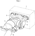
- a reference numeral 1 denotes a direct injection gasoline engine of a motor vehicle
- a reference numeral 2 denotes an exhaust manifold of the engine 1.
- a catalytic converter 3 is coupled to a collecting part 2a of the exhaust manifold 2 via a connecting pipe 4, and a GPF (gasoline particulate filter) device 5 is directly connected to a downstream side of the catalytic converter 3 in an exhaust flow direction.
- An exhaust pipe 6 extends from the GPF device 5 toward the rear of the motor vehicle.
- the catalytic converter 3 is a two-bed type in which two honeycomb catalysts 7 and 8 on a front stage and a rear stage are arranged in series and housed in a catalyst container.
- the honeycomb catalyst 7 on the front stage is formed by supporting a first catalyst on a honeycomb carrier.
- the honeycomb catalyst 8 on the rear stage is formed by supporting a second catalyst on a honeycomb carrier.
- As each of the honeycomb carriers it is preferable to use a honeycomb carrier having a capacity of approximately 0.5 L to 1.5 L.
- the first catalyst exhibits activity on oxidation reaction of unsaturated high HC such as toluene at a temperature lower than that of the second catalyst.
- the second catalyst exhibits activity on oxidation reaction of saturated low HC such as isopentane at a temperature lower than that of the first catalyst.
- the GPF device 5 includes a filter 10 with a catalyst housed in a filter container.
- the filter 10 with a catalyst is formed by supporting the second catalyst on a ceramic filter body formed of an inorganic porous material such as cordierite, SiC, Si 3 N 4 , sialon, and AlTiO3.
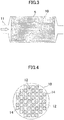
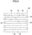
- the filter 10 with the catalyst is of a honeycomb structure and includes a multitude of cells 12 and 13 extending in parallel with one another. Inflow side cells 12, whose downstream ends are each blocked by a stopper 14, and outflow side cells 13, whose upstream ends are each blocked by a stopper 14, are alternately provided.
- the cell 12 and the cell 13 are separated from each other by a thin partition wall (exhaust gas passage wall) 15.
- a reference numeral 11 denotes an exhaust gas passage.
- Each hatched part in FIG. 4 shows the stopper 14 at an upstream end of an exhaust gas outflow passage 13.
- the filter body it is preferable to adopt a filter body having a capacity of 1.0 L to 2.0 L, a cell density of 200 cpsi to 300 cpsi, a thickness of each of the partition walls 15 of 150 ⁇ m to 250 ⁇ m, a porosity of each of the partition walls 15 of 40% to 60%, and a pore volume of each of the partition walls 15 of approximately 70 cm 3 to 400 cm 3 .
- the exhaust gas flows into the inflow side cells 12 of the filter 10 with the catalyst, passes through the partition walls 15 around the cells 12, and flows out to the outflow side cells 13 which respectively neighbor thereto, as indicated by arrows.
- each of the partition walls 15 has fine pores 16 for causing the cells 12 and the cells 13 to communicate with each other, and the exhaust gas passes through the pores 16.
- PM in the exhaust gas adheres mainly to walls of the cells 12 and the pores 16 and is deposited thereon.
- the second catalyst 17 is supported on surfaces (filter surfaces) of the partition walls 15 constituting the inflow side cells 12 and on inner surfaces of the pores 16.
- the second catalyst 17 is supported on the surfaces of the partition walls 15 constituting the cells 12 more thickly than on the inner surfaces of the pores 16. It is preferable that an amount of the supported second catalyst per unit area of the surfaces of the partition walls 15 is 50 times or more and 500 times or less as much as an amount of the supported second catalyst per unit area of the inner surfaces of the pores 16.
- an amount of the second catalyst supported on the surfaces of the partition walls 15 and the inner surfaces of the pores 16 per L of the filter body is approximately 20 g/L to 100 g/L. It is only required that an amount of the second catalyst supported on the surfaces of the partition walls 15 constituting the inflow side cells 12 is, for example, 15 g/L to 75 g/L of the filter body and an amount of the second catalyst supported on the inner surfaces of the pores 16 is, for example, 0.08 g to 0.37 g per unit pore volume.
- the first catalyst having high activity for purifying the unsaturated high HC preferable is a catalyst which contains, as an essential component, Pd-supported La 2 O 3 -containing alumina formed by supporting Pd on activated alumina containing 4% by mass of La 2 O 3 , further an OSC material (oxygen storage/release material) such as CeZr-based composite oxide, and an Rh catalyst formed by supporting Rh on the OSC material.
- Pd-supported La 2 O 3 -containing alumina formed by supporting Pd on activated alumina containing 4% by mass of La 2 O 3
- an OSC material oxygen storage/release material
- Rh catalyst formed by supporting Rh on the OSC material.
- the second catalyst having high activity for purifying the saturated low HC preferable is a catalyst which contains, as an essential component, Pt-supported La 2 O 3 -containing alumina formed by supporting Pt on activated alumina containing 4% by mass of La 2 O 3 and further, the above-mentioned OSC material.
- the front stage honeycomb catalyst 7 of the catalytic converter 3 contains the first catalyst which is excellent in purifying the unsaturated high HC
- the unsaturated high HC in the exhaust gas is oxidized and purified by the first catalyst, and a temperature of the exhaust gas is increased by catalytic reaction heat generated at that time.
- a temperature of the rear stage honeycomb catalyst 8 containing the second catalyst which is excellent in purifying the saturated low HC is increased. Accordingly, the saturated low HC in the exhaust gas is efficiently purified by the second catalyst of the rear stage honeycomb catalyst 8.
- a temperature of the exhaust gas is increased by the catalytic reaction heat due to the purification of HC by the honeycomb catalysts 7 and 8, such that the above-mentioned exhaust gas flows into the filter 10 with the catalyst on the downstream side. Therefore, the purification of the saturated low HC by the second catalyst of the filter 10 with the catalyst efficiently proceeds.
- saturated low HC is generated by cracking of the unsaturated high HC by the front-stage honeycomb catalyst 7 of the catalytic converter 3, and the saturated low HC flows to the rear stage honeycomb catalyst 8 and the filter 10 with the catalyst. Since the second catalysts of the rear stage honeycomb catalyst 8 and the filter 10 with the catalyst are excellent in purifying the unsaturated low HC, the saturated low HC generated by the above-mentioned cracking is efficiently purified by the second catalysts of the rear stage honeycomb catalyst 8 and the filter 10 with the catalyst.
- the second catalyst is thickly supported on the surfaces of the partition walls 15 constituting the inflow side cells 12 and is thinly supported on the inner surfaces of the pores 16. Accordingly, since the exhaust gas is actively purified on the surfaces of the partition walls 15, the exhaust gas whose temperature has been increased passes through the pores 16. Therefore, although the second catalyst is thinly supported on the inner surfaces of the pores 16, the temperature of the exhaust gas passing through the pores 16 is high and thus, the purification of the exhaust gas by the second catalyst efficiently proceeds.
- one end portion of the filter body (with a catalyst unsupported) 21 is immersed in catalyst slurry 23 of the above-mentioned second catalyst stored in a first container 22 and is pulled up.
- the inflow side cells 12 and the outflow side cells 13 are alternately provided.
- An upstream end side of the filter body 21 is immersed in the catalyst slurry 23 and is pulled up. This causes the catalyst slurry 23 to adhere to inner surfaces on an upstream end side of the inflow side cells 12 of the filter body 21.
- a vacuum pump 24 is connected to a downstream end of the filter body 21, and the pump 24 is operated to render a pressure of the outflow side cells 13 of the filter body 21 negative.
- the pressure of the outflow side cells 13 becomes negative, the catalyst slurry 23 adhering to the upstream end side of the inflow side cells 12 is attracted to downstream sides of the cells 12 and infiltrates into the pores 16 of the partition walls 15.
- the catalyst is supported on the inner surfaces of the pores 16 of the filter 21.
- the catalyst slurry 23 stored in the first container 22 is adjusted to have a viscosity at which the catalyst slurry 23 easily infiltrates into the pores 16 of the partition walls 15.
- the catalyst adhering to the inner surfaces of the pores 16 of the partition walls 15 is dried. This drying is conducted, for example, by holding the filter body 21 at a temperature of 150°C for two hours.
- An end portion of the dried filter body 21 on an upstream end side is immersed in catalyst slurry 26 of the above-mentioned second catalyst stored in a second container 25 and is pulled up. This causes the catalyst slurry 26 to adhere to the inner surfaces on an upstream side of the inflow side cells 12 of the filter body 21.
- a vacuum pump 24 is connected to a downstream end of the filter body 21, and the pump 24 is operated to render a pressure of the outflow side cells 13 of the filter body 21 negative.
- the pressure of the outflow side cell 13 becomes negative, the catalyst slurry 23 adhering to the upstream end side of the inflow side cells 12 is attracted to downstream sides of the cells 12.
- the catalyst is supported on the inner surfaces of the inflow side cells 12 of the filter 21, that is, on surfaces of the partition walls 15.
- the catalyst slurry 26 stored in the second container 25 is made to have a viscosity higher than that of the catalyst slurry 23 stored in the first container 22 so as to hinder the catalyst slurry 26 from entering the pores 16 of the partition walls 15 upon vacuuming performed by the vacuum pump 24.
- the catalyst slurry 26 When the catalyst slurry 26 is supported on the surfaces of the partition walls 15, although a part of the pores 16 are blocked, the catalyst slurry 26 supported on the surfaces of the partition walls 15 becomes porous catalyst layers by the subsequent calcination, thereby allowing the exhaust gas to pass through the catalyst layers and to flow into the pores 16.
- the catalyst adhering to the surfaces of the partition walls 15 of the filter body 21 and the catalyst adhering to the inner surfaces of the pores 16 are calcined.
- This calcining is conducted, for example, by holding the filter body 21 at a temperature of 500°C for two hours. If necessary, the drying step (in which the filter body 21 is held at the temperature of 150°C for two hours) is interposed prior to the calcining.
- the filter 10 with the catalyst in which the second catalyst is supported on the surfaces of the partition walls 15 and the inner surfaces of the pores 16 of the inflow side cells 12 of the filter body 21 is obtained.
- the GPF device 5 in which the filter 10 with the catalyst is housed in the filter container is connected to the catalytic converter 3 in which the honeycomb catalysts 7 and 8 are housed in the catalyst container, the catalytic converter 3 is connected to the exhaust manifold 2 via a connection pipe 4, and the GPF device 5 is joined to the exhaust pipe 6.
- the device for treating exhaust gas from an engine is obtained.
- a filter formed of cordierite and having a capacity of 1.3 L was prepared as the filter body 21 .
- a cell density thereof was 250 cpsi
- a partition wall thickness was 200 ⁇ m
- a porosity of each of the partition walls was 50%
- a pore volume of each of the partition walls was approximately 100 cm 3 .
- Example 2 a filter with a catalyst was obtained by supporting 15 g/L of the second catalyst (the supported amount in the above-mentioned first step) on inner surfaces of pores of the filter body 21 and supporting 45 g/L of the second catalyst (the supported amount in the above-mentioned second step) on surfaces of partition walls constituting inflow side cells 12.
- a filter with a catalyst was obtained by supporting 60 g/L of the second catalyst on inner surfaces of pores of the filter body 21. An amount of catalyst supported on surfaces of partition walls constituting inflow side cells 12 was set to zero. An amount of the supported catalyst per unit area of the inner surfaces of the pores was 0.23 g/m 2 .
- Table 1 shows that by supporting the catalyst on the surfaces of partition walls constituting the inflow side cells 12 as in Example, the temperature of the exhaust gas flowing into the pores due to the catalytic reaction heat is increased, which is advantageous in purification of the exhaust gas by the catalyst supported on the inner surfaces of pores.
- Amounts of supported catalyst in Example and Comparative Example were the same, 60 g/L.
- a total amount of the catalyst was supported on the inner surfaces of the pores, whereas in Example, the amount of catalyst supported on the inner surfaces of the pores was set to 15 g/L by supporting 3/4 of a total amount of the catalyst on the surfaces of partition walls constituting the inflow side cells 12. Therefore, in the filter in Example, a porosity of the partition walls was approximately 5.4% larger than that of the filter in Comparative Example.
- Example 2 The exhaust pressure loss in Example was approximately 93% of that in Comparative Example. This result shows that by supporting a portion of the catalyst on the surfaces of partition walls constituting the inflow side cells 12 as in Example, the exhaust pressure loss becomes small, thereby leading to advantages in enhancing scavenging performance of an engine and thus, in enhancing fuel consumption.
Landscapes
- Chemical & Material Sciences (AREA)
- Engineering & Computer Science (AREA)
- Chemical Kinetics & Catalysis (AREA)
- Combustion & Propulsion (AREA)
- General Engineering & Computer Science (AREA)
- Mechanical Engineering (AREA)
- Materials Engineering (AREA)
- Organic Chemistry (AREA)
- Health & Medical Sciences (AREA)
- Toxicology (AREA)
- Physics & Mathematics (AREA)
- General Chemical & Material Sciences (AREA)
- Environmental & Geological Engineering (AREA)
- Oil, Petroleum & Natural Gas (AREA)
- Analytical Chemistry (AREA)
- Biomedical Technology (AREA)
- Geometry (AREA)
- Thermal Sciences (AREA)
- Geology (AREA)
- Life Sciences & Earth Sciences (AREA)
- Exhaust Gas Treatment By Means Of Catalyst (AREA)
- Processes For Solid Components From Exhaust (AREA)
- Catalysts (AREA)
- Exhaust Gas After Treatment (AREA)
- Filtering Materials (AREA)
- Filtering Of Dispersed Particles In Gases (AREA)
Applications Claiming Priority (2)
| Application Number | Priority Date | Filing Date | Title |
|---|---|---|---|
| JP2017110551A JP6458827B2 (ja) | 2017-06-05 | 2017-06-05 | エンジンの排気ガス処理装置 |
| PCT/JP2018/019879 WO2018225514A1 (ja) | 2017-06-05 | 2018-05-23 | エンジンの排気ガス処理装置及びその製造方法 |
Publications (3)
| Publication Number | Publication Date |
|---|---|
| EP3617465A1 true EP3617465A1 (de) | 2020-03-04 |
| EP3617465A4 EP3617465A4 (de) | 2020-04-08 |
| EP3617465B1 EP3617465B1 (de) | 2023-04-19 |
Family
ID=64566269
Family Applications (1)
| Application Number | Title | Priority Date | Filing Date |
|---|---|---|---|
| EP18814241.8A Active EP3617465B1 (de) | 2017-06-05 | 2018-05-23 | Vorrichtung zur behandlung von abgas aus einem motor und verfahren zur herstellung der vorrichtung |
Country Status (5)
| Country | Link |
|---|---|
| US (1) | US10870082B2 (de) |
| EP (1) | EP3617465B1 (de) |
| JP (1) | JP6458827B2 (de) |
| CN (1) | CN110709588B (de) |
| WO (1) | WO2018225514A1 (de) |
Family Cites Families (22)
| Publication number | Priority date | Publication date | Assignee | Title |
|---|---|---|---|---|
| JP3879522B2 (ja) * | 2002-01-28 | 2007-02-14 | トヨタ自動車株式会社 | 内燃機関の排気浄化装置、および、該排気浄化装置のパティキュレートフィルタに触媒を担持させる触媒担持方法 |
| JP3936238B2 (ja) * | 2002-05-20 | 2007-06-27 | 株式会社デンソー | 触媒体および触媒体の製造方法 |
| US20040176246A1 (en) * | 2003-03-05 | 2004-09-09 | 3M Innovative Properties Company | Catalyzing filters and methods of making |
| JP4907860B2 (ja) * | 2004-11-11 | 2012-04-04 | 株式会社キャタラー | フィルタ触媒 |
| US8883667B2 (en) * | 2006-10-11 | 2014-11-11 | Nikki-Universal Co., Ltd. | Purification catalyst for reflow furnace gas, method for preventing contamination of reflow furnace, and reflow furnace |
| EP2269731B1 (de) | 2008-04-22 | 2012-07-11 | Honda Motor Co., Ltd. | Oxidationskatalysator und oxidationskatalysatorvorrichtung zur abgasreinigung |
| JP5409070B2 (ja) | 2009-03-24 | 2014-02-05 | 日本碍子株式会社 | 排ガス浄化装置の製造方法及び排ガス浄化装置 |
| CN102380412B (zh) * | 2011-09-06 | 2014-04-30 | 太原理工大学 | 负载过渡元素mfi催化剂的制备方法及其mfi催化剂应用 |
| GB201200783D0 (en) | 2011-12-12 | 2012-02-29 | Johnson Matthey Plc | Substrate monolith comprising SCR catalyst |
| JP5939010B2 (ja) * | 2012-04-18 | 2016-06-22 | マツダ株式会社 | 排気ガス浄化用触媒装置 |
| GB201219600D0 (en) * | 2012-10-31 | 2012-12-12 | Johnson Matthey Plc | Catalysed soot filter |
| JP6007864B2 (ja) | 2013-06-10 | 2016-10-12 | トヨタ自動車株式会社 | 排気浄化フィルタ |
| DE112014004876T5 (de) | 2013-10-23 | 2016-07-07 | Mazda Motor Corporation | Katalysatorvorrichtung für Abgasreinigung und Verfahren für Abgasreinigung |
| WO2015059904A1 (ja) | 2013-10-23 | 2015-04-30 | マツダ株式会社 | 排気ガス浄化触媒装置及び排気ガス浄化方法 |
| US10864502B2 (en) * | 2013-12-16 | 2020-12-15 | Basf Corporation | Manganese-containing diesel oxidation catalyst |
| DE112015000166T5 (de) | 2014-08-29 | 2016-05-25 | Mazda Motor Corporation | Abgasreinigungskatalysator und Abgasreinigungsverfahren |
| CN104234793A (zh) * | 2014-09-03 | 2014-12-24 | 江阴华音陶瓷机电科技有限公司 | 柴油机尾气过滤器 |
| US10232299B2 (en) | 2014-09-11 | 2019-03-19 | Ngk Insulators, Ltd. | Honeycomb structure |
| JP2016055282A (ja) * | 2014-09-11 | 2016-04-21 | 日本碍子株式会社 | ハニカム構造体 |
| JP6217677B2 (ja) * | 2015-03-24 | 2017-10-25 | マツダ株式会社 | 排気ガス浄化触媒装置及び排気ガス浄化方法 |
| JP6431823B2 (ja) | 2015-07-13 | 2018-11-28 | 株式会社Soken | 排ガス浄化フィルタ |
| JP6594149B2 (ja) | 2015-10-05 | 2019-10-23 | 株式会社キャタラー | 排ガス浄化装置 |
-
2017
- 2017-06-05 JP JP2017110551A patent/JP6458827B2/ja active Active
-
2018
- 2018-05-23 US US16/619,078 patent/US10870082B2/en active Active
- 2018-05-23 WO PCT/JP2018/019879 patent/WO2018225514A1/ja not_active Ceased
- 2018-05-23 EP EP18814241.8A patent/EP3617465B1/de active Active
- 2018-05-23 CN CN201880036612.2A patent/CN110709588B/zh not_active Expired - Fee Related
Also Published As
| Publication number | Publication date |
|---|---|
| EP3617465A4 (de) | 2020-04-08 |
| JP6458827B2 (ja) | 2019-01-30 |
| WO2018225514A1 (ja) | 2018-12-13 |
| US20200094188A1 (en) | 2020-03-26 |
| EP3617465B1 (de) | 2023-04-19 |
| JP2018204537A (ja) | 2018-12-27 |
| CN110709588B (zh) | 2021-10-22 |
| US10870082B2 (en) | 2020-12-22 |
| CN110709588A (zh) | 2020-01-17 |
Similar Documents
| Publication | Publication Date | Title |
|---|---|---|
| CN102711960B (zh) | 分区催化烟灰过滤器 | |
| US8844274B2 (en) | Compact diesel engine exhaust treatment system | |
| US8858904B2 (en) | Catalyzed soot filter | |
| KR102605894B1 (ko) | 막을 가진 촉매 벽 유동형 필터 | |
| JP6023395B2 (ja) | 触媒担持フィルタ | |
| JP2011509826A (ja) | 触媒フィルタ | |
| JP2011104524A (ja) | 触媒担持フィルタ、及び排ガス浄化システム | |
| CN109996595A (zh) | 具有部分表面涂层的催化壁流式过滤器 | |
| EP3636340A1 (de) | Katalysator zur abgasreinigung | |
| CN103415679B (zh) | 多功能废气净化过滤器和使用其的废气净化装置 | |
| US7560079B2 (en) | Exhaust gas-purifying apparatus | |
| JP7414413B2 (ja) | パティキュレートフィルタ | |
| US10870082B2 (en) | Device for treating exhaust gas from engine and method for manufacturing said device | |
| KR101933917B1 (ko) | Dpf의 채널 내부 표면 상 촉매 코팅방법 | |
| KR20130110136A (ko) | 다기능성 배기가스 정화필터 및 이를 이용한 배기가스 정화장치 | |
| KR20220075000A (ko) | 복합촉매층을 포함하는 디젤분진필터 장치 및 디젤분진필터 장치의 복합촉매층 형성방법 | |
| JP2022110535A (ja) | 排気浄化フィルタ |
Legal Events
| Date | Code | Title | Description |
|---|---|---|---|
| STAA | Information on the status of an ep patent application or granted ep patent |
Free format text: STATUS: THE INTERNATIONAL PUBLICATION HAS BEEN MADE |
|
| PUAI | Public reference made under article 153(3) epc to a published international application that has entered the european phase |
Free format text: ORIGINAL CODE: 0009012 |
|
| STAA | Information on the status of an ep patent application or granted ep patent |
Free format text: STATUS: REQUEST FOR EXAMINATION WAS MADE |
|
| REG | Reference to a national code |
Ref country code: DE Ref legal event code: R079 Ref document number: 602018048666 Country of ref document: DE Free format text: PREVIOUS MAIN CLASS: F01N0003035000 Ipc: B01D0039200000 |
|
| 17P | Request for examination filed |
Effective date: 20191128 |
|
| AK | Designated contracting states |
Kind code of ref document: A1 Designated state(s): AL AT BE BG CH CY CZ DE DK EE ES FI FR GB GR HR HU IE IS IT LI LT LU LV MC MK MT NL NO PL PT RO RS SE SI SK SM TR |
|
| AX | Request for extension of the european patent |
Extension state: BA ME |
|
| A4 | Supplementary search report drawn up and despatched |
Effective date: 20200306 |
|
| RIC1 | Information provided on ipc code assigned before grant |
Ipc: F01N 3/24 20060101ALI20200302BHEP Ipc: F01N 3/10 20060101ALI20200302BHEP Ipc: F01N 3/28 20060101ALI20200302BHEP Ipc: B01D 39/20 20060101AFI20200302BHEP Ipc: F01N 3/035 20060101ALI20200302BHEP Ipc: B01D 46/00 20060101ALI20200302BHEP Ipc: F01N 3/022 20060101ALI20200302BHEP Ipc: F01N 13/00 20100101ALI20200302BHEP Ipc: B01D 53/94 20060101ALI20200302BHEP Ipc: F01N 3/033 20060101ALI20200302BHEP |
|
| DAV | Request for validation of the european patent (deleted) | ||
| DAX | Request for extension of the european patent (deleted) | ||
| STAA | Information on the status of an ep patent application or granted ep patent |
Free format text: STATUS: EXAMINATION IS IN PROGRESS |
|
| 17Q | First examination report despatched |
Effective date: 20210304 |
|
| GRAP | Despatch of communication of intention to grant a patent |
Free format text: ORIGINAL CODE: EPIDOSNIGR1 |
|
| STAA | Information on the status of an ep patent application or granted ep patent |
Free format text: STATUS: GRANT OF PATENT IS INTENDED |
|
| INTG | Intention to grant announced |
Effective date: 20221206 |
|
| GRAS | Grant fee paid |
Free format text: ORIGINAL CODE: EPIDOSNIGR3 |
|
| GRAA | (expected) grant |
Free format text: ORIGINAL CODE: 0009210 |
|
| STAA | Information on the status of an ep patent application or granted ep patent |
Free format text: STATUS: THE PATENT HAS BEEN GRANTED |
|
| AK | Designated contracting states |
Kind code of ref document: B1 Designated state(s): AL AT BE BG CH CY CZ DE DK EE ES FI FR GB GR HR HU IE IS IT LI LT LU LV MC MK MT NL NO PL PT RO RS SE SI SK SM TR |
|
| REG | Reference to a national code |
Ref country code: GB Ref legal event code: FG4D |
|
| REG | Reference to a national code |
Ref country code: CH Ref legal event code: EP |
|
| REG | Reference to a national code |
Ref country code: DE Ref legal event code: R096 Ref document number: 602018048666 Country of ref document: DE |
|
| REG | Reference to a national code |
Ref country code: IE Ref legal event code: FG4D |
|
| REG | Reference to a national code |
Ref country code: AT Ref legal event code: REF Ref document number: 1560784 Country of ref document: AT Kind code of ref document: T Effective date: 20230515 |
|
| REG | Reference to a national code |
Ref country code: LT Ref legal event code: MG9D |
|
| REG | Reference to a national code |
Ref country code: NL Ref legal event code: MP Effective date: 20230419 |
|
| REG | Reference to a national code |
Ref country code: AT Ref legal event code: MK05 Ref document number: 1560784 Country of ref document: AT Kind code of ref document: T Effective date: 20230419 |
|
| PG25 | Lapsed in a contracting state [announced via postgrant information from national office to epo] |
Ref country code: NL Free format text: LAPSE BECAUSE OF FAILURE TO SUBMIT A TRANSLATION OF THE DESCRIPTION OR TO PAY THE FEE WITHIN THE PRESCRIBED TIME-LIMIT Effective date: 20230419 |
|
| PG25 | Lapsed in a contracting state [announced via postgrant information from national office to epo] |
Ref country code: SE Free format text: LAPSE BECAUSE OF FAILURE TO SUBMIT A TRANSLATION OF THE DESCRIPTION OR TO PAY THE FEE WITHIN THE PRESCRIBED TIME-LIMIT Effective date: 20230419 Ref country code: PT Free format text: LAPSE BECAUSE OF FAILURE TO SUBMIT A TRANSLATION OF THE DESCRIPTION OR TO PAY THE FEE WITHIN THE PRESCRIBED TIME-LIMIT Effective date: 20230821 Ref country code: NO Free format text: LAPSE BECAUSE OF FAILURE TO SUBMIT A TRANSLATION OF THE DESCRIPTION OR TO PAY THE FEE WITHIN THE PRESCRIBED TIME-LIMIT Effective date: 20230719 Ref country code: ES Free format text: LAPSE BECAUSE OF FAILURE TO SUBMIT A TRANSLATION OF THE DESCRIPTION OR TO PAY THE FEE WITHIN THE PRESCRIBED TIME-LIMIT Effective date: 20230419 Ref country code: AT Free format text: LAPSE BECAUSE OF FAILURE TO SUBMIT A TRANSLATION OF THE DESCRIPTION OR TO PAY THE FEE WITHIN THE PRESCRIBED TIME-LIMIT Effective date: 20230419 |
|
| PG25 | Lapsed in a contracting state [announced via postgrant information from national office to epo] |
Ref country code: RS Free format text: LAPSE BECAUSE OF FAILURE TO SUBMIT A TRANSLATION OF THE DESCRIPTION OR TO PAY THE FEE WITHIN THE PRESCRIBED TIME-LIMIT Effective date: 20230419 Ref country code: PL Free format text: LAPSE BECAUSE OF FAILURE TO SUBMIT A TRANSLATION OF THE DESCRIPTION OR TO PAY THE FEE WITHIN THE PRESCRIBED TIME-LIMIT Effective date: 20230419 Ref country code: LV Free format text: LAPSE BECAUSE OF FAILURE TO SUBMIT A TRANSLATION OF THE DESCRIPTION OR TO PAY THE FEE WITHIN THE PRESCRIBED TIME-LIMIT Effective date: 20230419 Ref country code: LT Free format text: LAPSE BECAUSE OF FAILURE TO SUBMIT A TRANSLATION OF THE DESCRIPTION OR TO PAY THE FEE WITHIN THE PRESCRIBED TIME-LIMIT Effective date: 20230419 Ref country code: IS Free format text: LAPSE BECAUSE OF FAILURE TO SUBMIT A TRANSLATION OF THE DESCRIPTION OR TO PAY THE FEE WITHIN THE PRESCRIBED TIME-LIMIT Effective date: 20230819 Ref country code: HR Free format text: LAPSE BECAUSE OF FAILURE TO SUBMIT A TRANSLATION OF THE DESCRIPTION OR TO PAY THE FEE WITHIN THE PRESCRIBED TIME-LIMIT Effective date: 20230419 Ref country code: GR Free format text: LAPSE BECAUSE OF FAILURE TO SUBMIT A TRANSLATION OF THE DESCRIPTION OR TO PAY THE FEE WITHIN THE PRESCRIBED TIME-LIMIT Effective date: 20230720 Ref country code: AL Free format text: LAPSE BECAUSE OF FAILURE TO SUBMIT A TRANSLATION OF THE DESCRIPTION OR TO PAY THE FEE WITHIN THE PRESCRIBED TIME-LIMIT Effective date: 20230419 |
|
| PG25 | Lapsed in a contracting state [announced via postgrant information from national office to epo] |
Ref country code: FI Free format text: LAPSE BECAUSE OF FAILURE TO SUBMIT A TRANSLATION OF THE DESCRIPTION OR TO PAY THE FEE WITHIN THE PRESCRIBED TIME-LIMIT Effective date: 20230419 |
|
| REG | Reference to a national code |
Ref country code: CH Ref legal event code: PL |
|
| PG25 | Lapsed in a contracting state [announced via postgrant information from national office to epo] |
Ref country code: SK Free format text: LAPSE BECAUSE OF FAILURE TO SUBMIT A TRANSLATION OF THE DESCRIPTION OR TO PAY THE FEE WITHIN THE PRESCRIBED TIME-LIMIT Effective date: 20230419 |
|
| PG25 | Lapsed in a contracting state [announced via postgrant information from national office to epo] |
Ref country code: MC Free format text: LAPSE BECAUSE OF FAILURE TO SUBMIT A TRANSLATION OF THE DESCRIPTION OR TO PAY THE FEE WITHIN THE PRESCRIBED TIME-LIMIT Effective date: 20230419 |
|
| REG | Reference to a national code |
Ref country code: DE Ref legal event code: R097 Ref document number: 602018048666 Country of ref document: DE |
|
| REG | Reference to a national code |
Ref country code: BE Ref legal event code: MM Effective date: 20230531 |
|
| PG25 | Lapsed in a contracting state [announced via postgrant information from national office to epo] |
Ref country code: SM Free format text: LAPSE BECAUSE OF FAILURE TO SUBMIT A TRANSLATION OF THE DESCRIPTION OR TO PAY THE FEE WITHIN THE PRESCRIBED TIME-LIMIT Effective date: 20230419 Ref country code: SK Free format text: LAPSE BECAUSE OF FAILURE TO SUBMIT A TRANSLATION OF THE DESCRIPTION OR TO PAY THE FEE WITHIN THE PRESCRIBED TIME-LIMIT Effective date: 20230419 Ref country code: RO Free format text: LAPSE BECAUSE OF FAILURE TO SUBMIT A TRANSLATION OF THE DESCRIPTION OR TO PAY THE FEE WITHIN THE PRESCRIBED TIME-LIMIT Effective date: 20230419 Ref country code: MC Free format text: LAPSE BECAUSE OF FAILURE TO SUBMIT A TRANSLATION OF THE DESCRIPTION OR TO PAY THE FEE WITHIN THE PRESCRIBED TIME-LIMIT Effective date: 20230419 Ref country code: LU Free format text: LAPSE BECAUSE OF NON-PAYMENT OF DUE FEES Effective date: 20230523 Ref country code: LI Free format text: LAPSE BECAUSE OF NON-PAYMENT OF DUE FEES Effective date: 20230531 Ref country code: EE Free format text: LAPSE BECAUSE OF FAILURE TO SUBMIT A TRANSLATION OF THE DESCRIPTION OR TO PAY THE FEE WITHIN THE PRESCRIBED TIME-LIMIT Effective date: 20230419 Ref country code: DK Free format text: LAPSE BECAUSE OF FAILURE TO SUBMIT A TRANSLATION OF THE DESCRIPTION OR TO PAY THE FEE WITHIN THE PRESCRIBED TIME-LIMIT Effective date: 20230419 Ref country code: CZ Free format text: LAPSE BECAUSE OF FAILURE TO SUBMIT A TRANSLATION OF THE DESCRIPTION OR TO PAY THE FEE WITHIN THE PRESCRIBED TIME-LIMIT Effective date: 20230419 Ref country code: CH Free format text: LAPSE BECAUSE OF NON-PAYMENT OF DUE FEES Effective date: 20230531 |
|
| PLBE | No opposition filed within time limit |
Free format text: ORIGINAL CODE: 0009261 |
|
| STAA | Information on the status of an ep patent application or granted ep patent |
Free format text: STATUS: NO OPPOSITION FILED WITHIN TIME LIMIT |
|
| REG | Reference to a national code |
Ref country code: IE Ref legal event code: MM4A |
|
| 26N | No opposition filed |
Effective date: 20240122 |
|
| GBPC | Gb: european patent ceased through non-payment of renewal fee |
Effective date: 20230719 |
|
| PG25 | Lapsed in a contracting state [announced via postgrant information from national office to epo] |
Ref country code: IE Free format text: LAPSE BECAUSE OF NON-PAYMENT OF DUE FEES Effective date: 20230523 |
|
| PG25 | Lapsed in a contracting state [announced via postgrant information from national office to epo] |
Ref country code: IE Free format text: LAPSE BECAUSE OF NON-PAYMENT OF DUE FEES Effective date: 20230523 Ref country code: GB Free format text: LAPSE BECAUSE OF NON-PAYMENT OF DUE FEES Effective date: 20230719 |
|
| PG25 | Lapsed in a contracting state [announced via postgrant information from national office to epo] |
Ref country code: SI Free format text: LAPSE BECAUSE OF FAILURE TO SUBMIT A TRANSLATION OF THE DESCRIPTION OR TO PAY THE FEE WITHIN THE PRESCRIBED TIME-LIMIT Effective date: 20230419 |
|
| PG25 | Lapsed in a contracting state [announced via postgrant information from national office to epo] |
Ref country code: SI Free format text: LAPSE BECAUSE OF FAILURE TO SUBMIT A TRANSLATION OF THE DESCRIPTION OR TO PAY THE FEE WITHIN THE PRESCRIBED TIME-LIMIT Effective date: 20230419 Ref country code: IT Free format text: LAPSE BECAUSE OF FAILURE TO SUBMIT A TRANSLATION OF THE DESCRIPTION OR TO PAY THE FEE WITHIN THE PRESCRIBED TIME-LIMIT Effective date: 20230419 Ref country code: FR Free format text: LAPSE BECAUSE OF NON-PAYMENT OF DUE FEES Effective date: 20230619 Ref country code: BE Free format text: LAPSE BECAUSE OF NON-PAYMENT OF DUE FEES Effective date: 20230531 |
|
| PG25 | Lapsed in a contracting state [announced via postgrant information from national office to epo] |
Ref country code: BG Free format text: LAPSE BECAUSE OF FAILURE TO SUBMIT A TRANSLATION OF THE DESCRIPTION OR TO PAY THE FEE WITHIN THE PRESCRIBED TIME-LIMIT Effective date: 20230419 |
|
| PG25 | Lapsed in a contracting state [announced via postgrant information from national office to epo] |
Ref country code: BG Free format text: LAPSE BECAUSE OF FAILURE TO SUBMIT A TRANSLATION OF THE DESCRIPTION OR TO PAY THE FEE WITHIN THE PRESCRIBED TIME-LIMIT Effective date: 20230419 |
|
| PGFP | Annual fee paid to national office [announced via postgrant information from national office to epo] |
Ref country code: DE Payment date: 20250402 Year of fee payment: 8 |
|
| PG25 | Lapsed in a contracting state [announced via postgrant information from national office to epo] |
Ref country code: CY Free format text: LAPSE BECAUSE OF FAILURE TO SUBMIT A TRANSLATION OF THE DESCRIPTION OR TO PAY THE FEE WITHIN THE PRESCRIBED TIME-LIMIT; INVALID AB INITIO Effective date: 20180523 |
|
| PG25 | Lapsed in a contracting state [announced via postgrant information from national office to epo] |
Ref country code: HU Free format text: LAPSE BECAUSE OF FAILURE TO SUBMIT A TRANSLATION OF THE DESCRIPTION OR TO PAY THE FEE WITHIN THE PRESCRIBED TIME-LIMIT; INVALID AB INITIO Effective date: 20180523 |
|
| PG25 | Lapsed in a contracting state [announced via postgrant information from national office to epo] |
Ref country code: TR Free format text: LAPSE BECAUSE OF FAILURE TO SUBMIT A TRANSLATION OF THE DESCRIPTION OR TO PAY THE FEE WITHIN THE PRESCRIBED TIME-LIMIT Effective date: 20230419 |