EP3617496B1 - Windturbine mit schlankem schaufelblatt - Google Patents
Windturbine mit schlankem schaufelblatt Download PDFInfo
- Publication number
- EP3617496B1 EP3617496B1 EP19188863.5A EP19188863A EP3617496B1 EP 3617496 B1 EP3617496 B1 EP 3617496B1 EP 19188863 A EP19188863 A EP 19188863A EP 3617496 B1 EP3617496 B1 EP 3617496B1
- Authority
- EP
- European Patent Office
- Prior art keywords
- blade
- larger
- wind turbine
- chord
- lift
- Prior art date
- Legal status (The legal status is an assumption and is not a legal conclusion. Google has not performed a legal analysis and makes no representation as to the accuracy of the status listed.)
- Active
Links
Images


Classifications
-
- F—MECHANICAL ENGINEERING; LIGHTING; HEATING; WEAPONS; BLASTING
- F03—MACHINES OR ENGINES FOR LIQUIDS; WIND, SPRING, OR WEIGHT MOTORS; PRODUCING MECHANICAL POWER OR A REACTIVE PROPULSIVE THRUST, NOT OTHERWISE PROVIDED FOR
- F03D—WIND MOTORS
- F03D7/00—Controlling wind motors
- F03D7/02—Controlling wind motors the wind motors having rotation axis substantially parallel to the air flow entering the rotor
- F03D7/0256—Stall control
-
- F—MECHANICAL ENGINEERING; LIGHTING; HEATING; WEAPONS; BLASTING
- F03—MACHINES OR ENGINES FOR LIQUIDS; WIND, SPRING, OR WEIGHT MOTORS; PRODUCING MECHANICAL POWER OR A REACTIVE PROPULSIVE THRUST, NOT OTHERWISE PROVIDED FOR
- F03D—WIND MOTORS
- F03D1/00—Wind motors with rotation axis substantially parallel to the air flow entering the rotor
- F03D1/06—Rotors
- F03D1/0608—Rotors characterised by their aerodynamic shape
- F03D1/0633—Rotors characterised by their aerodynamic shape of the blades
-
- F—MECHANICAL ENGINEERING; LIGHTING; HEATING; WEAPONS; BLASTING
- F03—MACHINES OR ENGINES FOR LIQUIDS; WIND, SPRING, OR WEIGHT MOTORS; PRODUCING MECHANICAL POWER OR A REACTIVE PROPULSIVE THRUST, NOT OTHERWISE PROVIDED FOR
- F03D—WIND MOTORS
- F03D1/00—Wind motors with rotation axis substantially parallel to the air flow entering the rotor
- F03D1/06—Rotors
- F03D1/0608—Rotors characterised by their aerodynamic shape
- F03D1/0633—Rotors characterised by their aerodynamic shape of the blades
- F03D1/0641—Rotors characterised by their aerodynamic shape of the blades of the section profile of the blades, i.e. aerofoil profile
-
- F—MECHANICAL ENGINEERING; LIGHTING; HEATING; WEAPONS; BLASTING
- F05—INDEXING SCHEMES RELATING TO ENGINES OR PUMPS IN VARIOUS SUBCLASSES OF CLASSES F01-F04
- F05B—INDEXING SCHEME RELATING TO WIND, SPRING, WEIGHT, INERTIA OR LIKE MOTORS, TO MACHINES OR ENGINES FOR LIQUIDS COVERED BY SUBCLASSES F03B, F03D AND F03G
- F05B2240/00—Components
- F05B2240/10—Stators
- F05B2240/12—Fluid guiding means, e.g. vanes
- F05B2240/122—Vortex generators, turbulators, or the like, for mixing
-
- F—MECHANICAL ENGINEERING; LIGHTING; HEATING; WEAPONS; BLASTING
- F05—INDEXING SCHEMES RELATING TO ENGINES OR PUMPS IN VARIOUS SUBCLASSES OF CLASSES F01-F04
- F05B—INDEXING SCHEME RELATING TO WIND, SPRING, WEIGHT, INERTIA OR LIKE MOTORS, TO MACHINES OR ENGINES FOR LIQUIDS COVERED BY SUBCLASSES F03B, F03D AND F03G
- F05B2240/00—Components
- F05B2240/20—Rotors
- F05B2240/30—Characteristics of rotor blades, i.e. of any element transforming dynamic fluid energy to or from rotational energy and being attached to a rotor
- F05B2240/306—Surface measures
- F05B2240/3062—Vortex generators
-
- Y—GENERAL TAGGING OF NEW TECHNOLOGICAL DEVELOPMENTS; GENERAL TAGGING OF CROSS-SECTIONAL TECHNOLOGIES SPANNING OVER SEVERAL SECTIONS OF THE IPC; TECHNICAL SUBJECTS COVERED BY FORMER USPC CROSS-REFERENCE ART COLLECTIONS [XRACs] AND DIGESTS
- Y02—TECHNOLOGIES OR APPLICATIONS FOR MITIGATION OR ADAPTATION AGAINST CLIMATE CHANGE
- Y02E—REDUCTION OF GREENHOUSE GAS [GHG] EMISSIONS, RELATED TO ENERGY GENERATION, TRANSMISSION OR DISTRIBUTION
- Y02E10/00—Energy generation through renewable energy sources
- Y02E10/70—Wind energy
- Y02E10/72—Wind turbines with rotation axis in wind direction
Definitions
- Wind turbine comprising a rotor with airfoils with a reduced ratio between the variation of the lift force and the average lift force.
- the undisturbed wind speed V is the wind speed at the locus of the axis of the rotor when the wind turbine does not disturb the flow.
- An airfoil is a for the aerodynamics optimized profile which is round at the leading edge and sharp or cut off at the trailing edge. One side of the airfoil is the upper side or suction side, the other side is the lower side or the pressure side.
- the curve through the centres of circles within the airfoil touching both the lower side and the upper side is called the camber line. At the leading edge this line continues to the airfoil contour.
- the line part which connects the most forward and the most backward part of the camber line is the chord c or the local chord c r at radial position r .
- a rotor blade may exist of several airfoils at the same radial position. In such a case the sum of the chords of the airfoils should be taken as the locale chord c r .
- the leading edge of the airfoil is located at 0% of the chord (0% c ) and the trailing edge at 100% c .
- the largest distance between the camber line and the chord is the camber.
- the ratio between the diameter of the largest circle in the airfoil and the chord is the thickness t of the airfoil.
- Flexible or in position controllable parts of the aft part of the airfoil, which can move more than 2.5% c with respect to the leading edge are not part of the chord.
- C M .
- M a dimensionless momentum loss
- C is the chord number which is Nrc r c l ⁇ 2 /( 2 ⁇ R 2 ) for a horizontal axis turbine and Nrc r c l ⁇ 2 / R 2 for a vertical axis turbine.
- This number prescribes how the parameters N , c r , c l , r, R and ⁇ should be chosen in order to realise a certain dimensionless momentum loss in the flow. Close to the axis of rotation, the chord number does not provide good values and therefore this number is primary useful in the range starting at 0.3 R -0.6 R and ending at 0.9 R -1.0 R .
- Example for a horizontal axis wind turbine with M 3 4 .
- the power coefficient C p P /(1 ⁇ 2 ⁇ AV 3 ), in which P is the power extracted from the flow according to the Lanchester-Betz theory, ⁇ is the air density and A the swept area ⁇ R 2 .
- the extracted power P will be higher than the electric power P e due to transfer losses.
- P nom the nominal or rated power
- P 1.2 P e .
- the pitch angle is 0° when the local chord at 0.99 R is located in the plane in which the blade is rotating. The angle becomes more positive when the blade pitches towards vane position.
- the angle of attack is the angle between the chord and the undisturbed inflow in a 2D situation.
- the angle of attack at which the blade develops zero lift is the 0-lift angle.
- the lift (coefficient) increases approximately linear with the angle of attack for small angles of attack (e.g. between -8o and +8o).
- Most pitch regulated variable speed turbines operate essentially at or near constant tip speed ratio ⁇ below rated wind speed. The turbine may deviate from this constant ⁇ operation e.g. to avoid certain eigenfrequencies or to decrease sound emission. Still it is optimised for a certain ⁇ design and the airfoils operate on average at the angle of attack ⁇ design which gives optimum performance.
- the airfoil develops a lift coefficient c l,design and has a lift over drag ratio L / D design .
- a common method to characterise a wind turbine is to bin parameters like the 10-minute averaged power or angle of attack or lift coefficient as a function of the 10 minute averaged wind speed. When many data points are collected in each bin and averaged a more or less accurate estimate of the averages of those parameters is obtained. The so obtained value of for example a lift coefficient at a certain wind speed is the mean lift coefficient or the 10 minute averaged lift coefficient. If the turbine is produced conform the design, those mean or 10 minute averaged values correspond to the design values.
- the 10 minute averaged value and the mean value of a parameter such as the lift coefficient or angle of attack are equivalent.
- the angle at which the airfoil stalls or the flow separates from the surface is airfoil dependent.
- a typical stall angle is +10°, at which the lift coefficient is about 1.0 to 1.6.
- c l increases slightly or even decreases and simultaneously c d increases, so that the efficiency of the rotor blades drops.
- Lift enhancing means such as known in literature.
- lift enhancing means are vortex generators (VGs), gurney flaps, lengthening of the chord, increase of camber, suction of the boundary layer, flaps near the leading edge or near the trailing edge, deformation of a flexible part at the trailing edge of the airfoil, application of the Magnus effect, FCS such as described in Sinha, S.K., WO03067169 , synthetic jets which feed energy into the boundary layer such as is known by e.g. Gerhard, L., US4674717 and MEM translational tabs.
- control can be by pneumatics, hydraulics, electromagnetics, piezo electrics, by MEM translational tabs or any other control method known from literature. All those lift enhancing means can principally be attached as separate elements to the blade or can be integrated with the blade.
- VGs are elements which generate vortices which feed energy into the boundary layer.
- VGs can be elements which are more or less submerged in the surface and are known in many different shapes. Examples are a special curvature of the airfoil surface itself (e.g. cavities) or surfaces which extend from the airfoil surface into the flow.
- Possible connection parts such as a base which is connected to the VG, is not counted as part as the VG.
- the chord position of the VG is related to the part of the VG at the smallest chord position.
- the base can be essentially flat or following the local airfoil shape.
- VGs may have a length of about 3% of the chord, a height of about 1% of the chord and a mutual distance of about 5% of the chord.
- Airfoils with VGs reach typical lift coefficients of 1.5-2.5 at angles of attack of e.g. +12° tot +25°.
- VGs at regular spacing attached essentially in a line biased less than 30° from the line perpendicular to the flow direction is defined as a basis line of VGs. Tangentials are circles around the centre of rotation in the plane of rotation of the applicable airfoils.
- WO 00/15961 A1 discloses a wind turbine blade with a plurality of vortex generators projecting from its lee surface for controlling the boundary layer separation.
- Each vortex generator is formed as a solid and in a top view substantially wedge-shaped body defined by two lateral faces arranged substantially perpendicular to the surface of the blade, when seen in a top view said faces extending mutually divergently from a tip, which faces toward the leading edge of the blade, to the trailing edge of the blade.
- Each vortex generator is furthermore in downstream direction defined by a rear face and in upstream direction by a top face. When seen in the direction from the tip toward the rear face along a transverse plane of the blade, the top face extends non-convergently such that the height at the tip is less or equal to its height at the rear face.
- WO 2005/035978 A1 discloses a rotor blade for a wind power station, comprising a profiled member that is provided with a relative thickness which decreases towards the outside from a root to a tip of the blade.
- Said profiled member has a leading edge and a trailing edge as well as a suction side and a pressure side while generating a negative pressure relative to the pressure side on the suction side when being flown against by moved air, said negative pressure resulting in buoyancy.
- the suction side of the rotor blade encompasses a device for optimizing the flow around the profiled member.
- the rotor blade is provided with at least one planar element that extends substantially in the direction of flow, protrudes from the suction side, and is arranged in the zone of a transversal flow which runs from the root to the tip of the blade on the suction side of the profiled member.
- the height and length of the planar element are selected such that the element causes said transversal flow to be effectively reduced.
- US 3,578,264 A discloses a boundary layer control for delay or prevention of flow separation and/or increase in rate of heat exchange between a surface and a fluid by an arrangement of surface elements which may take the form of either crests or discreet concave depressions in the surface, having effective depths or dimensions of less that of the adjacent boundary layer thickness, to cause the formation of vortices with succeeded surface elements being positioned to cause vortex amplification, for effective boundary layer mixing with less drag, weight penalty, noise, and energy loss than that of conventional vane type generators.
- WO 90/11929 A describes a generally V-shaped device that is installed on a surface over which there is a flowing medium whose viscosity causes a boundary layer to form between free-stream medium and the surface.
- the point of the V shape generator is oriented facing the downstream direction.
- a plurality of generators are positioned in a line crosswise to the flow spaced so that the vortices created thereby do not interfere.
- Flow between the arms of each generator generates a pair of counterrotating vortices with diameters much larger than the height of the generator to provide stronger flow control with less parasitic drag than prior art vortex generators.
- the height of the generator is usually less than the height of the local boundary layer, but may extend above the boundary layer, especially when the generator is used to control span wise flow or to reduce tip vortices.
- EP 1152148 A discloses a balancing of aerodynamic optimization and structural optimization that provides a family of airfoils for wind turbines.
- Mathematic modeling yields maximum aerodynamic criteria that are coupled with a structural analysis to modify the optimum aerodynamic design into a balanced, and optimized airfoil configuration.
- the resulting airfoils have substantial performance impact on GROSS ANNUAL ENERGY PRODUCTION (GAEP).
- GAEP GROSS ANNUAL ENERGY PRODUCTION
- the airfoil is based on the theoretical optimum aerodynamic structure modified as required to maximize structural integrity.
- the method for maximizing airfoil performance permits the design of airfoils of predictable performance while achieving necessary structural integrity.
- the family of airfoils having operational and structural characteristics includes thickness-to-chord ratios ranging from 14% to 45%, a design lift coefficient in the range of 1.10-1.25 and a design Reynolds number in the range of 3 million to 8 million.
- Wind turbine costs are high because of the loads which require much material. Therefore turbine designers aim at high electricity production at low loads.
- a disadvantage of the present wind turbines is that the loads by the wind vary and that this variation leads to additional costs.
- An extreme case of a disadvantageous load variation is that wherein a blade bends so much that it hits the tower. At wind speeds above V cut-out the turbine has to be stopped to avoid overloading, which reduces production and adds uncertainty to the predicted production.
- Another disadvantage is relevant at high wind speeds when turbines are usually halted. The wind pressure on the blades causes high loads because the required chord of the turbine blades is large.
- a further disadvantage is that the loads increase when turbines are operated in the wake of other turbines and need to be placed far apart which costs space and additional cable length.
- a further disadvantage is that the high moments require much and strong material in the case of slender blades. Overcoming this disadvantage by the application of thick airfoils may lead to flow separation thus more drag and less lift.
- Another disadvantage of actual wind turbines is that the induction near the centre of a wind turbine rotor is less than further outside. This 'leak' in the rotor centre reduces the pressure difference over the rotor and therefore reduces the power.
- a further disadvantage of present rotors is that the blade performance degrades substantially by contamination.
- the aim of the invention is to reduce the ratio between the variation of the lift force and the average lift force of wind turbine blades and more in general to overcome the mentioned disadvantages.
- This aim is reached by replacing the state of the art airfoils by airfoils with a 10 minute averaged lift coefficient of more than 1.1, particularly more than 1.2 and more particularly more than 1.4 and preferably about 1.6 in the range between 0.5 R and 0.95 R .
- Special benefit is obtained by using airfoils between 0.4 R and 0.95 R with a mean lift coefficient which is higher than 1.5 and in particular higher than 1.75 and more particularly higher than 2.0 in a part of the operating range excluding extreme conditions.
- the product cc l should have a minimum value to reach the required lift.
- the designer can freely choose c and c l as long as the product cc l is larger that this minimum. Without notice the designer applies the same argument to lift variations, which is not correct.
- the lift variations are unlike the lift essentially independent of the lift coefficient c l .
- the designer uses this new insight, he would reduce c and increase c l , so that the lift variations become less. This is especially relevant in the outer part ( r > 0.5 R ) of the rotor.
- airfoils which operate on 10 minute averaged angles of attack which deviate from the 0-lift angle by more than 10°, and particularly more than 12° and more particularly more than 14° and preferably about 16°.
- the dimensionless momentum loss M can be determined in many ways.
- the maximum lift coefficient is now e.g. 1.8 at an angle of attack of 15°.
- the rotor is designed so that the average angle of attack is 12° and the average lift coefficient is 1.5. Since the lift is proportional to the product of chord and lift coefficient for small ⁇ , we choose the chord smaller by a factor of 1.5, so that the lift and thus the yield are equal. Due to turbulence the angle of attack varies in this case between 9° and 15° without stalling. With furthermore the same assumptions it follows that the lift coefficient varies between 1.2 and 1.8.
- the loads on the blades will be less by about the same factor as the chord reduction.
- a parking position of particular benefit is when the pitch angle is set outside the range of 30° - 100°.
- load mitigation according to the invention is that less (expensive) turbine control options are required.
- the common active controlled options are pitch control (to vane or to stall) and variable rotation speed.
- a preferred embodiment of the invention considers a wind turbine with 2 and particularly 1 or more particularly 0 active control options selected from the said active control options.
- Preferred embodiments of the invention have a ratio c l,max / c l,min less than -1.2 -0.2 ⁇ %cam and in particular less than -1.4 -0.2 ⁇ %cam, wherein c l,max is the maximum lift at positive angle of attack, c l,min is the maximum lift at negative angles of attack and %cam is the camber in percent of the chord, so when the camber is 6% said ratio is preferably larger than 2.2 and in particular 2.4. Therefore less measures (addition of foam or application of a higher percentage second type fibres) are required at the aerodynamic suction side to avoid buckling.
- air inlets such as slits in the airfoil at the suction side between 5% c and 60% c .
- Those inlets are preferably located in the radial range of 0.05 R to 0.5 R .
- These inlets are connected to channels in the blade which run to larger radial positions and which have an opening at the trailing edge of the blade. The centrifugal force on the air in the channel provides a natural suction.
- Further advantage is obtained by connecting inlets of more than 10% difference in radial position to different channels. Further advantage is obtained when the inlets can be opened or closed actively by using MEM tabs or piezoelectrics.
- the suction side as pressure side and the pressure side as suction side, in particular at wind speeds above 12 m/s and more particularly above 14 m/s.
- the nacelle is yawed over 180° so that the rotor changes from upwind to downwind operation. In this case the direction of rotation of the rotor remains the same.
- the blades up side down the variation of the lift force developed by the entire blade is less, the extreme lift force is less and the lift force acts on a smaller radial position, so that yaw and blade root moments are less.
- the invention is particularly relevant for turbines with a rotor diameter larger than 60m, particularly larger than 80m and more particular larger than 100m.
- the reduced chord according to the invention may require more material to carry the loads.
- the blades can be split in an upper blade and a lower blade at e.g. 0.2 R -0.7 R .
- the first type fibres at the pressure side continue from the non-divided outer part of the blade in the upper blade.
- the first type fibres at the suction side of the non-divided outer part of the blade continue in the lower blade.
- the upper and the lower blade reach a mutual distance of at least 5% R and particularly at least 10% R .
- the asymmetric aerodynamic behaviour of the blades leads to the situation that the upper blades takes mainly pressure loads and the lower blades take mainly tensile loads.
- the lower blade preferably has a 20% and particularly 40% and more particularly a 60% shorter chord than the upper blade at equal radial positions.
- a further advantage is that the addition of the chords of the lower and the upper blades increases the yield because 'leakage' from pressure side to the suction side is avoided.
- VGs are preferably placed close to the trailing edge at chord positions larger than 30%c, particularly larger than 50%c and more particularly larger than 70%c.
- airfoil with a camber of more than 6%c and particularly of more than 8%c and more particularly of more than 10%c avoids a deep suction peak at large angles of attack, which reduces sensitivity to contamination.
- airfoils with high camber often have a high L / D ratio at large angles of attack.
- VGs or basis line of VGs When multiple VGs or basis line of VGs are located behind each other in flow direction, one can speak about front, middle and rear VGs.
- the front VGs correspond to the VGs at the smallest chord position
- the rear VGs to those at the largest chord position and those in between are the middle VGs. Further advantage is obtained when the VGs in the middle are larger than the front ones and particularly when they are also larger than the rear ones.
- VGs upstream with respect to the basis line of VGs.
- the additional VGs keep the flow longer attached up to the basis line downstream.
- Those additional VGs reduce hysteresis of the c ⁇ ⁇ relation when ⁇ passes the stall angle.
- Those VGs can be located between 3%c at the pressure side and 10%c at the suction side and more particularly between 0%c and 5%c at the suction side. It is beneficial when VGs which are located behind each other in flow direction generate vortices of the same rotational direction.
- VGs which extend e.g. more than 10% c or even more than 30%c in chord direction.
- the blade surface is provided with ribs under an angle with the flow, of which the upflow part preferably is located at a smaller radial position than the downflow part.
- angles of attack In the case of a vertical axis turbine the angles of attack also vary without turbulence.
- the angle of attack variation is inversely proportional to the tip speed ratio ⁇ .
- ⁇ should not become less than about 41 ⁇ 2.
- the airfoils stall.
- Application of airfoils with VGs on both sides delays stall to larger angles of attack so that a ⁇ of 4, 31 ⁇ 2, 3 or even 21 ⁇ 2 can be used without stalling.
- a further advantage for the VAT turbine (when used in air or in water) is that it becomes self starting by attachment of VGs at less than 20%c, particularly less than 15%c and more in particular at less than 10%c on both the suction and pressure side of an airfoil or hydrofoil.
- VGs (1, 2, 4 or another number) and the ground plate are manufactured as one piece or even as a tape of a flexible material such as rubber, polyurethane or an elastomer possibly with additives to block UV-radiation.
- This is called a VG-element and is favourably manufactured of plastics of the families PVDF, FEP, PEEK, PI, PEI, PES and PFTE.
- the VG-element can be attached to the rotor blade with any known technique. It is of particular advantage to provide the ground plate partly of double sided adhesive and partly with fluid adhesive such as a cyanoacrylate.
- the double sided adhesive provides direct fixation after which the fluid glue has time to harden.
- the VGs can be attached with a hinge and only fold out after the blades are installed to the turbine.
- the side of the ground plate which will be attached to the blade can be slightly concave with a radius of curvature which is smaller than the radius of curvature of the blade at the position of attachment.
- the VGs have curvature in flow direction so that the angle between the flow without VG disturbance and the VG increases by preferably 5°to 15° in flow direction and particularly increases in the range of 2°to 30° are effective. This curvature avoids Kelvin-Helmholtz instability of the VGs and so increases durability.
- the old rotor is preferably replaced by a new rotor which has in the range of 0.6 R to 0.95 R a chord which is at least 10% less and preferably at least 20% at equal radial positions and more particularly is provided with VGs in that range.
- VG-pattern adaptations are: Increasing the size of VGs (e.g. 25%), reducing the spacing in between VGs (e.g. 25%), placing more VGs (e.g. an additional basis line), increasing the angle between the flow and VGs (e.g. by 5°), changing the position of the VGs (e.g. 5%c), etc.
- the tip speed ratio may be reduced.
- adaptation of the blades to more optimal operation at higher angles of attack is preferred.
- Other cases wherein adaptability is also relevant are when blades of about the same design are used for different wind climates or on different turbines.
- controllable VGs This can be used to decrease the maximum lift above rated wind speed, which may be reason to increase the cut out wind speed. It also can be used as a method to decrease the torque of the rotor in case of a failure, emergency stop or manual stop, which lowers the cost of other brake systems.
- the VGs can be switched to an effective state when a delay of low separation is preferred and to ineffective states when not.
- the VGs are be controlled by piezoelectrics or by MEM tabs and in particular by cylindrical MEM devices or piezoelectrics which enable a direct rotation of the vortex generator over e.g. 15°.
- the VG can be attached to this piezoelectric or MEM device so that its orientation to the flow can change from non-effective to effective.
- the effectiveness may be controlled by changing the angle between the VG and the flow, by folding it in or by retracting it more or less in the airfoil surface.
- Controllable VGs have the advantage of a faster response compared to pitching a blade.
- a preferred embodiment of the invention concerns a wind turbine with fixed rotor blades and controllable vortex generators.
- a rotor blade according to the invention of at least one strengthened point such as a hoisting point which is suitable for lifting the blade where by this point preferably is located at less than 1 chord length of the centre of mass of the blade. This avoids damage to the VGs since a hoisting band around the blade is not needed during the installation of the blade.
- Figure 1 shows a plot of the lift L versus the angle of attack ⁇ .
- Curve 3 shows the relation for a classical airfoil without lift enhancing means.
- the flow should enter the airfoil under an angle of attack 5. Due to e.g. turbulence in the wind the angle of attack varies in range 6 and therefore the lift will vary in range 7.
- An airfoil according to the invention with a higher lift coefficient and a shorter chord behaving like curve 8 should reach the same lift 4. This is realised at a larger angle of attack 9.
- the angle of attack varies in range 10 which is as wide as range 6.
- the lift variation 11 of the airfoil with the higher lift coefficient is less than the lift variation 7 of the classical airfoil.
- FIG 2 shows as example of the invention an upwind turbine 13 with tower 14 and nacelle 15.
- the turbine rotor of radius R comprises a hub 16 and blades 18 with tip 19 and root 17.
- On the rear side of the blade VGs are installed which are not visible in the figure.
- the blades are rotating in the direction of tangential 20 and comprise a leading edge 21 and a trailing edge 22.
- Figures 3 to 7 show airfoil cross sections I-I indicated in figure 2 .
- the cross sections show the suction sides 34 and the pressure sides 35.
- Figure 3 shows the angle of attack ⁇ 27 the extended chord 25 and the undisturbed flow 26.
- the line through the centres of the circles 36 is the camber line 37. This line intersects with the chord 38 of length 39.
- the leading edge of the airfoil is shown by 21 and the trailing edge by 22.
- front 42, middle 43 and rear 44 VGs are applied and on the pressure side also VGs 41 are applied.
- Figure 4 shows another realisation of VGs 45 on small chord position and VGs 44 on a larger chord position.
- the flexible trailing edge 49 shown in two positions in range 50 is not counted as part of the chord 29 if range 50 is more than 2.5%c with respect to the leading edge.
- the blade comprises first type fibres at the suction side 46 and at the pressure side 47 which extend perpendicular to the cross sections.
- the shear web 48 is located in between the suction side and pressure side.
- Figure 5 shows two oblique rows of VGs of which the front VG 61 of the upper line in the figure is located upstream relative to the most rear VG 62 of the lower line.
- VGs 61 and 62 generate vortices of the same direction of rotation.
- Figure 6 shows the front base line with VGs 63 and the rear base line with VGs 64.
- Figure 7 shows VGs 65 which extend over a relatively large part of the chord.
- Figure 8 shows turbine 15 of figure 2 directly after the blades 18 with VGs 68 were turned around to the up side down position which is illustrated by arrows 68. In this up side down application of the blades the function of the aerodynamic pressure and suction sides are exchanged and the rotor rotates in opposite direction.
- Figure 9 shows turbine 15 with a 2-bladed rotor of which the blades 18 split at division 75 in an upper blade 77 and a lower blade 76 which are connected at the extension of the main shaft 78.
- air can flow through the free spaces 79 between the upper blade and the lower blade, which upper blade and lower blade reach a distance 74 at the same radial position.
- the local chord is the sum of the chord of the upper blade and the chord of the lower blade at equal radial position.
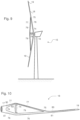
- Figure 10 shows a blade 18 with tip 19 and root 17.
- the substantially first type fibres 81 on the structural pressure side run from the blade root via the upper blade 76 and the division 75 towards the tip 19.
- the first type fibres 80 at the structural tensile side run from the root 17 via the lower blade 77 and the division 75 towards the blade tip 19.
- Spacer 82 is located between the upper and lower blade.
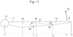
- Figure 11 shows a blade 18 of a wind turbine with an inlet 85 at radial position r 1 which sucks in boundary layer air which suction is driven by the centrifugal force on the air in channel 87 which runs to the outlet 86 at radial position r 11 .
- Inlet 88 is located relative to inlet 85 at the larger radial position r 2 and preferably has a stronger suction than inlet 85 and therefore this inlet has a separate channel 90 which preferably extends further in radial direction than channel 87. Channel 90 ducts the suck air to outlet 89 at radial position r 22 .
Landscapes
- Engineering & Computer Science (AREA)
- Life Sciences & Earth Sciences (AREA)
- Sustainable Development (AREA)
- Sustainable Energy (AREA)
- Chemical & Material Sciences (AREA)
- Combustion & Propulsion (AREA)
- Mechanical Engineering (AREA)
- General Engineering & Computer Science (AREA)
- Physics & Mathematics (AREA)
- Fluid Mechanics (AREA)
- Wind Motors (AREA)
Claims (13)
- Windenergieanlage (13), die einen Rotor mit wenigstens 100m Durchmesser aufweist, wobei der Rotor ein Rotorblatt (18) mit einem aerodynamischen Profil aufweist, dadurch gekennzeichnet, dass das Profil in dem Bereich von 0,2R bis 0,95R und insbesondere von 0,5R bis 0,95R einen Designauftriebskoeffizienten cl größer als 1,1, insbesondere größer als 1,2 und weiter insbesondere größer als 1,4 und weiter insbesondere bevorzugt etwa 1,6 aufweist und wobei das Rotorblatt Profile von wenigstens 25% Dicke aufweist, die an Radiuspositionen größer als 0,55R, insbesondere größer als 0,65R und weiter insbesondere größer als 0,75R, verwendet werden.
- Windenergieanlage nach Anspruch 1, wobei für Schnelllaufzahlen λ, die zu ungestörten Windgeschwindigkeiten zwischen 8 und 10 m/s gehören, die Profiltiefenzahl D (= Ncrλ2/R2) für das Rotorblatt zwischen 0,5R und 0,8R und/oder die Profiltiefenzahl
D , die über den Bereich zwischen 0,5R und 0,8R gemittelt ist, niedriger als 3,00 und insbesondere niedriger als 2,75 und weiter insbesondere niedriger als 2,50 ist. - Windenergieanlage nach einem der vorstehenden Ansprüche, wobei in einem Fall, dass der Leistungskoeffizient


C = M folgt, angenommen dass cl = 1,1 und insbesondere dass cl = 1,3 und weiter insbesondere dass cl = 1,5 und weiter insbesondere dass es vorzugsweise ungefähr 1,7 ist. - Windenergieanlage nach einem der vorstehenden Ansprüche, wobei innerhalb des Bereiches von 0,4R bis 0,95R und insbesondere von 0,5R bis 0,8R ein Auftriebserhöhungsmittel in dem Rotorblatt integriert ist oder als separates Element daran befestigt ist und wobei das Auftriebserhöhungsmittel insbesondere Vortexgeneratoren aufweist.
- Windenergieanlage nach einem der vorstehenden Ansprüche, die eine erste Art Fasern, die zwischen 5%c und 70%c auf beiden der aerodynamischen Druckseite und der aerodynamischen Saugseite angeordnet sind, aufweist, wobei der Querschnitt der ersten Art Fasern auf der Saugseite verglichen mit dem Querschnitt der ersten Art Fasern auf der Druckseite in dem Radiusbereich zwischen 0,3R und 0,7R wenigstens 20% größer und insbesondere wenigstens 30% größer und weiter insbesondere wenigstens 40% größer ist.
- Windenergieanlage nach einem der vorstehenden Ansprüche, mit einem an der Saugseite angeordnetem Einlass (85), der zwischen 5%R und 70%R angeordnet ist, wobei der Einlass (85) über einen Kanal (87) mit einem Auslass (86), angeordnet an einer Radiusposition, die relativ zu dem Einlass mindestens um einen Faktor


- Windenergieanlage nach einem der vorstehenden Ansprüche der Horizontalachsenart, wobei das Rotorblatt in der Richtung von der Spitze (19) zu der Wurzel (17) an einer Radiusposition zwischen 0,7R und 0,2R sich an einer Teilung (75) in ein oberes Blatt (76) und ein unteres Blatt (77) mit einem freien Raum (79) dazwischen aufspaltet, wobei sowohl das obere Blatt und das untere Blatt zu dem aerodynamischen Auftrieb beitragen, wobei insbesondere der Abstand (74) zwischen dem unteren und dem oberen Blatt an einer bestimmten Radiusposition größer als 5%R und weiter insbesondere größer als 10%R ist.
- Windenergieanlage nach einem der vorstehenden Ansprüche, wobei das Rotorblatt Vortexgeneratoren (41) aufweist, die an der Druckseite eines Profils, das vorzugsweise dicker als 25%c und insbesondere 30%c und weiter insbesondere 35%c ist, angeordnet sind, wobei die Vortexgeneratoren (41) insbesondere an Sehnenpositionen größer als 30%c, insbesondere größer als 50%c und weiter insbesondere größer als 70%c angeordnet sind.
- Windenergieanlage nach einem der vorstehenden Ansprüche, wobei das Rotorblatt ein Strömungsprofil mit einer Wölbung von mehr als 6%c insbesondere mehr als 8%c und weiter insbesondere mehr als 10%c aufweist.
- Windenergieanlage nach einem der vorstehenden Ansprüche wobei das Rotorblatt ein Strömungsprofil umfassend mindestens einen in Strömungsrichtung vorderen Vortexgenerator (42) und einen hinteren Vortexgenerator (44) und einen oder mehrere mittlere Vortexgeneratoren (43), umfasst, dadurch gekennzeichnet, dass die vorderen Vortexgeneratoren eine geringere Höhe als die durchschnittliche Höhe der mittleren Vortexgeneratoren haben und weiter insbesondere dass die hinteren Vortexgeneratoren auch eine geringere Höhe als die durchschnittliche Höhe der mittleren Vortexgeneratoren haben.
- Windenergieanlage nach einem der vorstehenden Ansprüche, wobei das Rotorblatt ein Strömungsprofil mit Vortexgeneratoren (42, 45), die zwischen 3%c auf der Druckseite und 10%c auf der Saugseite und weiter insbesondere zwischen 0%c und 5%c an der Saugseite angeordnet sind, umfasst, und/oder wobei das Rotorblatt ein Strömungsprofil mit Vortexgeneratoren (65), die eine Länge von über 10%c und weiter insbesondere von über 20%c und weiter insbesondere über 30%c haben, umfasst, wobei die Vortexgeneratoren insbesondere mit einem Winkel von weniger als 10° zu den Tangentialen bezogen auf den Drehmittelpunkt angeordnet sind.
- Windenergieanlage nach einem der vorstehenden Ansprüche, wobei die stromaufwärtige Seite von über 70% der Vortexgeneratoren einen kürzeren Abstand zu dem Drehmittelpunkt als die stromabwärtige Seite aufweist und/oder wobei Vortexgeneratoren gemäß einem Muster installiert sind, das sich in der Längsrichtung des Rotorblattes in der Position in Profiltiefenrichtung wenigstens einmal und insbesondere wenigstens zweimal erhöht.
- Windenergieanlage nach einem der vorstehenden Ansprüche, umfassend Strömungsprofilabschnitte wobei ein Verhältnis von cl,max/cl,min kleiner als -1,2 -0,2-%cam und insbesondere kleiner als -1,4 -0,2-%cam ist.
Applications Claiming Priority (4)
| Application Number | Priority Date | Filing Date | Title |
|---|---|---|---|
| NL1031492 | 2006-04-02 | ||
| NL2000302A NL2000302C1 (nl) | 2006-11-03 | 2006-11-03 | Windturbine met slank rotorblad. |
| EP07747361.9A EP2007981B1 (de) | 2006-04-02 | 2007-04-02 | Windturbine mit schlanker schaufel |
| PCT/NL2007/050137 WO2007114698A2 (en) | 2006-04-02 | 2007-04-02 | Wind turbine with slender blade |
Related Parent Applications (2)
| Application Number | Title | Priority Date | Filing Date |
|---|---|---|---|
| EP07747361.9A Division EP2007981B1 (de) | 2006-04-02 | 2007-04-02 | Windturbine mit schlanker schaufel |
| EP07747361.9A Division-Into EP2007981B1 (de) | 2006-04-02 | 2007-04-02 | Windturbine mit schlanker schaufel |
Publications (2)
| Publication Number | Publication Date |
|---|---|
| EP3617496A1 EP3617496A1 (de) | 2020-03-04 |
| EP3617496B1 true EP3617496B1 (de) | 2024-10-23 |
Family
ID=38472820
Family Applications (2)
| Application Number | Title | Priority Date | Filing Date |
|---|---|---|---|
| EP19188863.5A Active EP3617496B1 (de) | 2006-04-02 | 2007-04-02 | Windturbine mit schlankem schaufelblatt |
| EP07747361.9A Revoked EP2007981B1 (de) | 2006-04-02 | 2007-04-02 | Windturbine mit schlanker schaufel |
Family Applications After (1)
| Application Number | Title | Priority Date | Filing Date |
|---|---|---|---|
| EP07747361.9A Revoked EP2007981B1 (de) | 2006-04-02 | 2007-04-02 | Windturbine mit schlanker schaufel |
Country Status (10)
| Country | Link |
|---|---|
| US (1) | US8182231B2 (de) |
| EP (2) | EP3617496B1 (de) |
| CN (1) | CN101454564B (de) |
| AU (1) | AU2007232546A1 (de) |
| BR (1) | BRPI0709855A2 (de) |
| CA (1) | CA2647499C (de) |
| DK (2) | DK2007981T3 (de) |
| ES (2) | ES2999033T3 (de) |
| PT (2) | PT2007981T (de) |
| WO (1) | WO2007114698A2 (de) |
Families Citing this family (98)
| Publication number | Priority date | Publication date | Assignee | Title |
|---|---|---|---|---|
| EP1994281B1 (de) * | 2006-03-16 | 2013-05-22 | Vestas Wind Systems A/S | Verfahren und steuersystem zur verringerung von dauerbelastungen von komponenten einer windturbine, die einer asymmetrischen belastung der rotorebene ausgesetzt sind |
| PT2007981T (pt) | 2006-04-02 | 2021-02-11 | Wobben Properties Gmbh | Turbina eólica com pá esbelta |
| EP2132437B2 (de) * | 2007-03-30 | 2018-10-03 | Vestas Wind Systems A/S | Windturbine mit blattanstellwinkelverstellung |
| ES2339883T3 (es) | 2007-07-20 | 2010-05-26 | Siemens Aktiengesellschaft | Pala de rotor de turbina eolica y turbina eolica con regulacion de paso. |
| EP2031241A1 (de) * | 2007-08-29 | 2009-03-04 | Lm Glasfiber A/S | Rotorschaufel einer Windturbine mit Barriereerzeugungsvorrichtung |
| US8240990B2 (en) * | 2007-12-06 | 2012-08-14 | General Electric Company | Apparatus and method for reducing asymmetric rotor loads in wind turbines during shutdown |
| GB0803730D0 (en) * | 2008-02-29 | 2008-04-09 | Airbus Uk Ltd | Shock bump array |
| ES2343397B1 (es) * | 2008-03-07 | 2011-06-13 | GAMESA INNOVATION & TECHNOLOGY, S.L. | Una pala de aerogenerador. |
| WO2010023278A2 (en) | 2008-08-29 | 2010-03-04 | Vestas Wind Systems A/S | Control system in wind turbine blades |
| US9797368B2 (en) * | 2008-09-19 | 2017-10-24 | Cortenergy Bv | Wind turbine with low induction tips |
| US8096761B2 (en) | 2008-10-16 | 2012-01-17 | General Electric Company | Blade pitch management method and system |
| EP2141358A1 (de) * | 2008-12-12 | 2010-01-06 | Lm Glasfiber A/S | Windturbinenschaufel mit einem Spoiler mit effektiver Luftstromteilung |
| WO2010128656A1 (ja) * | 2009-05-08 | 2010-11-11 | Ueno Yasuo | 垂直軸風車装置 |
| EP2253838A1 (de) * | 2009-05-18 | 2010-11-24 | Lm Glasfiber A/S | Verfahren zum Betrieb einer Windkraftanlage |
| EP2253835A1 (de) * | 2009-05-18 | 2010-11-24 | Lm Glasfiber A/S | Windturbinenschaufel mit einem Basisteil mit einem nicht-positiven Sturz |
| EP2253837A1 (de) * | 2009-05-18 | 2010-11-24 | Lm Glasfiber A/S | Windturbinenschaufel mit Flusswechselelementen |
| ES2675953T3 (es) * | 2009-10-08 | 2018-07-13 | Lm Wind Power International Technology Ii Aps | Pala de turbina eólica con pluralidad de piezas de un dispositivo de guiado del flujo extendido longitudinalmente |
| WO2011106733A2 (en) * | 2010-02-25 | 2011-09-01 | The Regents Of The University Of California | Advanced aerodynamic and structural blade and wing design |
| US8061986B2 (en) * | 2010-06-11 | 2011-11-22 | General Electric Company | Wind turbine blades with controllable aerodynamic vortex elements |
| KR20110136296A (ko) * | 2010-06-14 | 2011-12-21 | 삼성중공업 주식회사 | 풍력 발전 장치용 블레이드 및 이를 이용한 풍력 발전 장치 |
| US8047801B2 (en) | 2010-06-23 | 2011-11-01 | General Electric Company | Wind turbine blades with aerodynamic vortex elements |
| US20110142595A1 (en) * | 2010-07-02 | 2011-06-16 | General Electric Company | Wind turbine blades with controlled active flow and vortex elements |
| DE102010026588B4 (de) * | 2010-07-08 | 2012-06-14 | Nordex Energy Gmbh | Windenergieanlagenrotorblatt mit optimierter Hinterkante |
| ES2966169T3 (es) | 2010-07-16 | 2024-04-18 | Lm Wind Power As | Pala de turbina eólica con hombro estrecho y perfiles de perfil alar relativamente gruesos |
| US8167554B2 (en) * | 2011-01-28 | 2012-05-01 | General Electric Corporation | Actuatable surface features for wind turbine rotor blades |
| EP2484896B1 (de) * | 2011-02-04 | 2014-04-23 | LM WP Patent Holding A/S | Montage von Wirbelerzeugern auf das Rotorblatt einer Windturbine mittels einer Montageplatte |
| EP2484898B1 (de) * | 2011-02-04 | 2014-04-23 | LM WP Patent Holding A/S | Wirbelerzeugervorrichtung mit verjüngten Abschnitten für eine Windturbine |
| EP2712401B1 (de) * | 2011-04-28 | 2016-10-05 | Vestas Wind Systems A/S | Verbesserte verfahren zur windturbinengeräuschkontrolle |
| CN103782027B (zh) * | 2011-05-16 | 2017-03-22 | Lm Wp 专利控股有限公司 | 具有噪音降低装置的风力涡轮机叶片及相关方法 |
| EP2532510B1 (de) * | 2011-06-07 | 2016-11-16 | Siemens Aktiengesellschaft | Verfahren zur Modifizierung der Oberflächenform einer Windturbinendrehschaufel |
| US8231344B2 (en) * | 2011-07-05 | 2012-07-31 | General Electric Company | Methods for controlling the amplitude modulation of noise generated by wind turbines |
| WO2013014015A2 (en) * | 2011-07-22 | 2013-01-31 | Lm Wind Power A/S | A vortex generator arrangement for an airfoil |
| EP2584193A1 (de) * | 2011-10-20 | 2013-04-24 | Siemens Aktiengesellschaft | Windturbine mit Luftdichtekorrektur des Anstellwinkels |
| US8777580B2 (en) | 2011-11-02 | 2014-07-15 | Siemens Aktiengesellschaft | Secondary airfoil mounted on stall fence on wind turbine blade |
| CN104114857B (zh) * | 2012-02-17 | 2017-03-08 | Lm Wp 专利控股有限公司 | 具有定形失速栅或偏流器的风轮机叶片 |
| ES2804061T3 (es) * | 2012-03-13 | 2021-02-02 | Wobben Properties Gmbh | Raiz de pala alabeada |
| US9151270B2 (en) | 2012-04-03 | 2015-10-06 | Siemens Aktiengesellschaft | Flatback slat for wind turbine |
| EP2836700A1 (de) * | 2012-04-10 | 2015-02-18 | Ogin, Inc. | Ummantelte flüssigkeitsturbine mit grenzschichterregungselementen |
| CN104364521B (zh) * | 2012-06-10 | 2017-06-06 | 维斯塔斯风力系统有限公司 | 风轮机的主轴承装置 |
| EP2713044B2 (de) * | 2012-09-28 | 2022-12-07 | Siemens Gamesa Renewable Energy A/S | Windturbinenlaufschaufel |
| DE102013207640B4 (de) * | 2012-10-16 | 2024-06-20 | Wobben Properties Gmbh | Windenergieanlagen-Rotorblatt |
| EP2787182B1 (de) | 2013-04-02 | 2018-06-06 | MTU Aero Engines AG | Leitschaufel für eine Strömungsmaschine, Leitschaufelgitter und Verfahren zur Herstellung einer Leitschaufel oder eines Leitschaufelgitters |
| US9562513B2 (en) | 2013-05-03 | 2017-02-07 | General Electric Company | Wind turbine rotor blade assembly with surface features |
| US9494132B2 (en) * | 2013-05-07 | 2016-11-15 | General Electric Company | Airflow modifying assembly for a rotor blade of a wind turbine |
| JP6189088B2 (ja) * | 2013-05-28 | 2017-08-30 | テラル株式会社 | ロータ |
| US9739259B2 (en) * | 2013-06-05 | 2017-08-22 | The Regents Of The University Of California | Wind turbine blade with biplane section |
| US9267491B2 (en) | 2013-07-02 | 2016-02-23 | General Electric Company | Wind turbine rotor blade having a spoiler |
| US9523279B2 (en) | 2013-11-12 | 2016-12-20 | General Electric Company | Rotor blade fence for a wind turbine |
| US10161252B2 (en) * | 2013-11-27 | 2018-12-25 | Rutgers, The State University Of New Jersey | Blade flow deflector |
| US10167845B2 (en) * | 2013-11-27 | 2019-01-01 | Rutgers, The State University Of New Jersey | Blade flow deflector |
| US9752559B2 (en) * | 2014-01-17 | 2017-09-05 | General Electric Company | Rotatable aerodynamic surface features for wind turbine rotor blades |
| US9670901B2 (en) * | 2014-03-21 | 2017-06-06 | Siemens Aktiengesellschaft | Trailing edge modifications for wind turbine airfoil |
| US9476406B2 (en) * | 2014-04-14 | 2016-10-25 | Siemens Aktiengesellschaft | Vortex generators aligned with trailing edge features on wind turbine blade |
| TR201909371T4 (tr) * | 2014-07-03 | 2019-07-22 | Lm Wp Patent Holding As | Bir rüzgar türbini kanadı. |
| DK3177827T3 (da) | 2014-08-05 | 2019-06-03 | Lm Wp Patent Holding As | Vindmøllevinge med overflademonteret indretning |
| CN104696158B (zh) * | 2014-08-20 | 2018-08-03 | 深圳市深田蒙业新能源有限公司 | 一种垂直轴风力发电机组升力型叶片翼型 |
| ES2612213T3 (es) * | 2014-12-22 | 2017-05-12 | Siemens Aktiengesellschaft | Pala de rotor con generadores de vórtices |
| US10400743B1 (en) * | 2014-12-24 | 2019-09-03 | National Technology & Engineering Solutions Of Sandia, Llc | Wind turbine blades, wind turbines, and wind farms having increased power output |
| US10087912B2 (en) | 2015-01-30 | 2018-10-02 | General Electric Company | Vortex generator for a rotor blade |
| US10180125B2 (en) * | 2015-04-20 | 2019-01-15 | General Electric Company | Airflow configuration for a wind turbine rotor blade |
| US9869295B2 (en) * | 2015-05-07 | 2018-01-16 | General Electric Company | Attachment method to install components, such as tip extensions and winglets, to a wind turbine blade, as well as the wind turbine blade and component |
| US9869296B2 (en) * | 2015-05-07 | 2018-01-16 | General Electric Company | Attachment method and system to install components, such as tip extensions and winglets, to a wind turbine blade |
| US10094358B2 (en) * | 2015-07-21 | 2018-10-09 | Winnova Energy LLC | Wind turbine blade with double airfoil profile |
| EP3203063A1 (de) * | 2016-02-03 | 2017-08-09 | Wilhelmus Helena Hendrikus Joosten | Windturbine, deren verwendung und schaufel zur verwendung in der turbine |
| US11143163B2 (en) * | 2016-03-08 | 2021-10-12 | Semtive Inc. | Vertical axis wind turbine |
| US10118696B1 (en) | 2016-03-31 | 2018-11-06 | Steven M. Hoffberg | Steerable rotating projectile |
| US10400744B2 (en) * | 2016-04-28 | 2019-09-03 | General Electric Company | Wind turbine blade with noise reducing micro boundary layer energizers |
| DK3267031T3 (da) * | 2016-07-05 | 2019-09-16 | Siemens Gamesa Renewable Energy As | Vindmøllerotorvinge med vortex generatorer |
| US10487798B2 (en) | 2016-08-05 | 2019-11-26 | General Electric Company | System and method for locating airflow modifiers for installation on a wind turbine rotor blade |
| US10487796B2 (en) | 2016-10-13 | 2019-11-26 | General Electric Company | Attachment methods for surface features of wind turbine rotor blades |
| US11536245B2 (en) * | 2017-01-26 | 2022-12-27 | General Electric Company | Rotor blade assembly and a wind turbine having the rotor blade assembly |
| US10465652B2 (en) | 2017-01-26 | 2019-11-05 | General Electric Company | Vortex generators for wind turbine rotor blades having noise-reducing features |
| RU2666093C1 (ru) * | 2017-04-25 | 2018-09-05 | Сергей Николаевич Низов | Аэродинамическая поверхность летательного аппарата |
| JP6732697B2 (ja) | 2017-07-05 | 2020-07-29 | 三菱重工業株式会社 | 風車翼へのボルテックスジェネレータの配置位置決定方法、風車翼アセンブリの製造方法及び風車翼アセンブリ |
| US20190024631A1 (en) * | 2017-07-20 | 2019-01-24 | General Electric Company | Airflow configuration for a wind turbine rotor blade |
| CN108223448A (zh) * | 2018-02-06 | 2018-06-29 | 李辉 | 一种高强度流线型扇叶 |
| US11712637B1 (en) | 2018-03-23 | 2023-08-01 | Steven M. Hoffberg | Steerable disk or ball |
| DK3587798T3 (da) * | 2018-06-27 | 2020-11-23 | Siemens Gamesa Renewable Energy As | Aerodynamisk konstruktion |
| EP3587799B1 (de) * | 2018-06-27 | 2025-06-18 | Siemens Gamesa Renewable Energy A/S | Aerodynamische struktur |
| CN109026520B (zh) * | 2018-07-26 | 2020-04-21 | 华北电力大学 | 风电叶片、风轮及根据桨距角确定风电叶片弦长的方法 |
| US10920742B2 (en) * | 2018-07-26 | 2021-02-16 | Institute of Nuclear Energy Research, Atomic Energy Council, Executive Yuan, R.O.C. | Noise-reduction device for wind turbine and the wind turbine applied thereof |
| EP3847368B1 (de) * | 2018-09-04 | 2026-04-29 | Biomerenewables Inc. | Fluidische turbinenstruktur |
| CN112956124A (zh) | 2018-09-12 | 2021-06-11 | 伊格纳西奥·华雷斯 | 微型逆变器及控制器 |
| EP3850213A1 (de) * | 2018-09-13 | 2021-07-21 | Vestas Wind Systems A/S | Windturbine mit einer blatttragenden struktur mit aerodynamischen eigenschaften |
| EP3730779A1 (de) * | 2019-04-25 | 2020-10-28 | Siemens Gamesa Renewable Energy A/S | Flüssigkeitsförderrohrsystem für windturbinenschaufel |
| DE102019113044A1 (de) | 2019-05-17 | 2020-11-19 | Wobben Properties Gmbh | Verfahren zum Auslegen und Betreiben einer Windenergieanlage, Windenergieanlage sowie Windpark |
| GB2587409A (en) * | 2019-09-27 | 2021-03-31 | Ogab Ltd | A wind turbine and method of generating power from the wind |
| EP3885572A1 (de) * | 2020-03-25 | 2021-09-29 | Siemens Gamesa Renewable Energy A/S | Verringerung der aerodynamischen belastung bei der schaufelmontage und -wartung einer windturbine |
| EP3907401A1 (de) * | 2020-05-05 | 2021-11-10 | Siemens Gamesa Renewable Energy A/S | Vorrichtung zur änderung des auftriebs eines rotorblatts, rotorblatt einer windturbine und verfahren zur änderung des auftriebs eines rotorblatts |
| EP3916218B1 (de) * | 2020-05-15 | 2024-04-03 | Wobben Properties GmbH | Verfahren zum auslegen und betreiben einer windenergieanlage, windenergieanlage sowie windpark |
| CN111879963B (zh) * | 2020-06-03 | 2022-05-31 | 山东嘉誉测试科技有限公司 | 一种风力监测装置 |
| EP4027006B1 (de) * | 2021-01-07 | 2025-03-05 | Nordex Energy SE & Co. KG | Rotorschaufel einer windturbine mit zwei reihen von wirbelgeneratoren |
| ES3056229T3 (en) * | 2021-01-10 | 2026-02-19 | General Electric Renovables Espana Sl | Wind turbine blades with deflector and method |
| EP4080039A1 (de) | 2021-04-19 | 2022-10-26 | Siemens Gamesa Renewable Energy A/S | Windturbinenschaufel und windturbine |
| EP4086455A1 (de) | 2021-05-07 | 2022-11-09 | Siemens Gamesa Renewable Energy A/S | Betrieb einer windkraftanlage zur nachlaufregelung |
| EP4112927B1 (de) | 2021-06-28 | 2024-04-03 | Siemens Gamesa Renewable Energy A/S | Handhabungsanordnung |
| US11746742B1 (en) * | 2021-08-26 | 2023-09-05 | National Technology & Engineering Solutions Of Sandia, Llc | Thrust-optimized blade design for wind turbines |
| US12404833B2 (en) | 2022-01-19 | 2025-09-02 | Power Curve Aps | Vortex generator |
Citations (8)
| Publication number | Priority date | Publication date | Assignee | Title |
|---|---|---|---|---|
| WO1992001865A1 (en) | 1990-07-26 | 1992-02-06 | Howden Wind Turbines Ltd. | Wind turbine blade and rotor incorporating same |
| US5417548A (en) | 1994-01-14 | 1995-05-23 | Midwest Research Institute | Root region airfoil for wind turbine |
| WO2000015961A1 (en) | 1998-09-16 | 2000-03-23 | Lm Glasfiber A/S | Wind turbine blade with vortex generator |
| WO2001016482A1 (en) | 1999-09-01 | 2001-03-08 | Stichting Energieonderzoek Centrum Nederland | Blade for a wind turbine |
| EP1152148A1 (de) * | 2000-05-01 | 2001-11-07 | Enron Wind Energy Systems Co. | Rotorblattprofile für Windenergieanlagen |
| EP1314885A1 (de) | 2001-11-26 | 2003-05-28 | Bonus Energy A/S | Gezahnte und flexible Windturbinenflügelhinterkante |
| WO2006090215A1 (en) | 2005-02-22 | 2006-08-31 | Vestas Wind Systems A/S | Wind turbine blade |
| WO2007114698A2 (en) | 2006-04-02 | 2007-10-11 | Gustave Paul Corten | Wind turbine with slender blade |
Family Cites Families (14)
| Publication number | Priority date | Publication date | Assignee | Title |
|---|---|---|---|---|
| US3578264A (en) | 1968-07-09 | 1971-05-11 | Battelle Development Corp | Boundary layer control of flow separation and heat exchange |
| DE3345154C2 (de) | 1983-12-14 | 1987-02-12 | Messerschmitt-Bölkow-Blohm GmbH, 8012 Ottobrunn | Tragflügel für Luftfahrzeuge |
| US5058837A (en) * | 1989-04-07 | 1991-10-22 | Wheeler Gary O | Low drag vortex generators |
| JP3192854B2 (ja) | 1993-12-28 | 2001-07-30 | 株式会社東芝 | タービン冷却翼 |
| US5562420A (en) | 1994-03-14 | 1996-10-08 | Midwest Research Institute | Airfoils for wind turbine |
| CA2144350A1 (en) | 1995-03-10 | 1996-09-11 | John Waring | Drag reducing arrangement for athlete |
| NL1004508C2 (nl) | 1996-11-12 | 1998-05-14 | Wubbo Johannes Ockels | Windgedreven aandrijfinrichting. |
| US6068446A (en) | 1997-11-20 | 2000-05-30 | Midwest Research Institute | Airfoils for wind turbine |
| US20030145980A1 (en) | 2002-02-04 | 2003-08-07 | Sinha Sumon Kumar | System and method for using a flexible composite surface for pressure-drop free heat transfer enhancement and flow drag reduction |
| NL1021078C1 (nl) | 2002-07-15 | 2004-01-16 | Energieonderzoek Ct Petten Ecn | Werkwijze en inrichting betreffende stromingsenergie zoals een windturbinepark. |
| DK1603735T3 (da) | 2003-03-06 | 2007-07-09 | Vestas Wind Sys As | Forbindelse imellem kompositter med ikke-kompatible egenskaber samt fremgangsmåde til fremstilling |
| NL1023666C2 (nl) | 2003-06-14 | 2004-12-20 | Energieonderzoek Ct Petten Ecn | Werkwijze of inrichting om energie aan een stromend fluïdum te onttrekken. |
| DE10347802B3 (de) * | 2003-10-10 | 2005-05-19 | Repower Systems Ag | Rotorblatt für eine Windkraftanlage |
| US8157533B2 (en) * | 2005-10-17 | 2012-04-17 | Vestas Wind Systems A/S | Wind turbine blade with variable aerodynamic profile |
-
2007
- 2007-04-02 PT PT77473619T patent/PT2007981T/pt unknown
- 2007-04-02 ES ES19188863T patent/ES2999033T3/es active Active
- 2007-04-02 ES ES07747361T patent/ES2855106T3/es active Active
- 2007-04-02 CA CA2647499A patent/CA2647499C/en active Active
- 2007-04-02 WO PCT/NL2007/050137 patent/WO2007114698A2/en not_active Ceased
- 2007-04-02 PT PT191888635T patent/PT3617496T/pt unknown
- 2007-04-02 CN CN200780019244.2A patent/CN101454564B/zh active Active
- 2007-04-02 DK DK07747361.9T patent/DK2007981T3/da active
- 2007-04-02 EP EP19188863.5A patent/EP3617496B1/de active Active
- 2007-04-02 EP EP07747361.9A patent/EP2007981B1/de not_active Revoked
- 2007-04-02 BR BRPI0709855-3A patent/BRPI0709855A2/pt active IP Right Grant
- 2007-04-02 AU AU2007232546A patent/AU2007232546A1/en not_active Abandoned
- 2007-04-02 DK DK19188863.5T patent/DK3617496T3/da active
-
2008
- 2008-10-02 US US12/244,186 patent/US8182231B2/en active Active
Patent Citations (9)
| Publication number | Priority date | Publication date | Assignee | Title |
|---|---|---|---|---|
| WO1992001865A1 (en) | 1990-07-26 | 1992-02-06 | Howden Wind Turbines Ltd. | Wind turbine blade and rotor incorporating same |
| US5417548A (en) | 1994-01-14 | 1995-05-23 | Midwest Research Institute | Root region airfoil for wind turbine |
| EP0663527A1 (de) | 1994-01-14 | 1995-07-19 | Midwest Research Institute | Wurzelprofil für Windturbine |
| WO2000015961A1 (en) | 1998-09-16 | 2000-03-23 | Lm Glasfiber A/S | Wind turbine blade with vortex generator |
| WO2001016482A1 (en) | 1999-09-01 | 2001-03-08 | Stichting Energieonderzoek Centrum Nederland | Blade for a wind turbine |
| EP1152148A1 (de) * | 2000-05-01 | 2001-11-07 | Enron Wind Energy Systems Co. | Rotorblattprofile für Windenergieanlagen |
| EP1314885A1 (de) | 2001-11-26 | 2003-05-28 | Bonus Energy A/S | Gezahnte und flexible Windturbinenflügelhinterkante |
| WO2006090215A1 (en) | 2005-02-22 | 2006-08-31 | Vestas Wind Systems A/S | Wind turbine blade |
| WO2007114698A2 (en) | 2006-04-02 | 2007-10-11 | Gustave Paul Corten | Wind turbine with slender blade |
Non-Patent Citations (20)
| Title |
|---|
| "Windkraftanlagen", 1 January 2008, SPRINGER, Heidelberg, ISBN: 978-3-540-72150-5, article HAU, ERIC: "Kapitel 5: Aerodynamik des Rotors", pages: 89 - 164, XP009558657 |
| CORTEN G. P.: "Flow Separation on Wind Turbine Blades", THESIS, UNIVERSITEIT UTRECHT, 16 January 2001 (2001-01-16), Universiteit Utrecht, XP055856559, Retrieved from the Internet <URL:https://dspace.library.uu.nl/bitstream/handle/1874/653/full.pdf> [retrieved on 20211101] |
| D26 - ENTSCHEIDUNGSBEGRÜNDUNG EP 07747361.9 |
| D27 - VORLÄUFIGE AUFFASSUNG BESCHWERDEKAMMER T1017/23-3.2.04 |
| D28 - PROTOKOLL MÜNDL. VERHANDLUNG T1017/23-3.2.04 |
| DAYTON A GRIFFIN, ET AL.: "Investigation of vortex generators for augmentation of wind turbine power performance", NREL TECHNICAL MONITOR NREL/SR-440-21399, 1 December 1996 (1996-12-01), XP055390597, Retrieved from the Internet <URL:https://www.nrel.gov/docs/legosti/old/21399.pdf> [retrieved on 20170713] |
| G E MILLER: "COMPARATIVE PERFORMANCE TESTS ON THE MOD-2, 2.5-MW WIND TURBINE WITH AND WITHOUT VORTEX GENERATORS", NASA TECHNICAL REPORT N95-27978, 1 May 1995 (1995-05-01), pages 67 - 77, XP055464339 |
| GYATT G. W.: "DEVELOPMENT AND TESTING OF VORTEX GENERATORS FOR SMALL HORIZONTAL AXIS WIND TURBINES.", FINAL REPORT DOE/NASA/0367-1, XX, XX, 1 July 1986 (1986-07-01), XX , pages A + B + C + 01 - 40 + ABSTRACT., XP000861589 |
| HANSEN M O L, CARSTEN HEIN WESTERGAARD: "Phenomenological Model of vortex generators", INTERNATIONAL ENERGY AGENCY, AERODYNAMICS OF WIND TURBINES, 9TH SYMPOSIUMAT: THE AERONAUTICAL INST. OF SWEDEN, (FFA), 1 December 1995 (1995-12-01), pages 1 - 7, XP055856555 |
| PETER FUGLSANG, CHRISTIAN BAK: "Development of the Risø wind turbine airfoils", WIND ENERGY, WILEY, CHICHESTER, GB, vol. 7, no. 2, 24 May 2004 (2004-05-24), GB , pages 145 - 162, XP002436915, ISSN: 1099-1824, DOI: 10.1002/we.117 |
| PETER FUGLSANG, ET AL.: "Wind tunnel tests of the FFA-W3-241, FFA-W3-301 and NACA 63-430 airfoils", RISO NATIONAL LABORATORY, 1 December 1998 (1998-12-01), XP055464772 |
| PETER FUGLSANG, ET AL.: "Wind Tunnel Tests of the Risoe-A1-18, Risoe-A1-21 and Risoe-A1-24 Airfoils", FINAL DRAFT RISO NATIONAL LABORATORY, 1 January 1999 (1999-01-01), pages 1 - 102, XP055390642, [retrieved on 20170713] |
| PETER FUGLSANG: "Design and Verification of the Risø-B1 Airfoil Family for Wind Turbines", TRANSACTIONS OF ASME, vol. 126, 1 November 2004 (2004-11-01), pages 1002 - 1010, XP055430802 |
| RUUD VAN ROOIJ ET AL: "03 May, 2004 1 DUWIND, section Wind Energy, Faculty CiTG Design of Airfoils for Wind Turbine Blades", 3 May 2004 (2004-05-03), XP055765005, Retrieved from the Internet <URL:https://gcep.stanford.edu/pdfs/energy_workshops_04_04/wind_van_rooij.pdf> [retrieved on 20210114] * |
| TIMOTHY L SULLIVAN, VIRGINIA HAMPTON _: "DOE/NASA/20320-59 NASA TM-83680 ' NASA-TM-836S0 Effect of Vortex Generators on the Power Conversion Performance and Structural Dynamic Loads of the Mod-2 Wind Turbine", 1 June 1984 (1984-06-01), XP055617603, Retrieved from the Internet <URL:https://ntrs.nasa.gov/archive/nasa/casi.ntrs.nasa.gov/19840021278.pdf> [retrieved on 20190902] |
| UNKNOWN: "Innovative Design Approaches for large wind turbine blades Final Report", SAND 2004-0074, UNLIMITED RELEASE, 1 May 2004 (2004-05-01), XP055276869, [retrieved on 20160601] |
| UNKNOWN: "Parametric Study for large wind turbine blades", SAND 2002-2519, UNLIMITED RELEASE, 1 August 2002 (2002-08-01), XP055276868, [retrieved on 20160601] |
| VAN ROOIJ R P J O M ; TIMMER W A: "ROUGHNESS SENSITIVITY CONSIDERATIONS FOR THICK ROTOR BLADE AIRFOILS", JOURNAL OF SOLAR ENERGY ENGINEERING., ASME INTERNATIONAL, US, vol. 125, no. 4, 1 November 2003 (2003-11-01), US , pages 468 - 478, XP008079790, ISSN: 0199-6231, DOI: 10.1115/1.1624614 |
| W. A. TIMMER, R. P. J. O. M. VAN ROOIJ: "Summary of the Delft University Wind Turbine Dedicated Airfoils", JOURNAL OF SOLAR ENERGY ENGINEERING., ASME INTERNATIONAL, US, vol. 125, no. 4, 1 January 2003 (2003-01-01), US , pages 488 - 496, XP055586939, ISSN: 0199-6231, DOI: 10.1115/1.1626129 |
| WETZEL K. K., FAROKHI S.: "INFLUENCE OF VORTEX GENERATORS ON NREL S807 AIRFOIL AERODYNAMIC CHARACTERISTICS AND WIND TURBINE PERFORMANCE.", WIND ENGINEERING., MULTI-SCIENCE PUBLISHING CO., BRENTWOOD, ESSEX., GB, vol. 19., no. 03., 1 January 1995 (1995-01-01), GB , pages 157 - 165., XP000516437, ISSN: 0309-524X |
Also Published As
| Publication number | Publication date |
|---|---|
| CA2647499C (en) | 2016-06-14 |
| BRPI0709855A2 (pt) | 2011-07-26 |
| PT3617496T (pt) | 2024-12-05 |
| ES2855106T3 (es) | 2021-09-23 |
| WO2007114698A3 (en) | 2007-12-06 |
| AU2007232546A1 (en) | 2007-10-11 |
| WO2007114698A2 (en) | 2007-10-11 |
| US8182231B2 (en) | 2012-05-22 |
| PT2007981T (pt) | 2021-02-11 |
| CA2647499A1 (en) | 2007-10-11 |
| EP3617496A1 (de) | 2020-03-04 |
| AU2007232546A2 (en) | 2008-12-11 |
| CN101454564A (zh) | 2009-06-10 |
| WO2007114698A8 (en) | 2008-11-27 |
| DK2007981T3 (da) | 2021-03-01 |
| CN101454564B (zh) | 2014-04-23 |
| EP2007981A2 (de) | 2008-12-31 |
| DK3617496T3 (da) | 2024-12-02 |
| EP2007981B1 (de) | 2021-01-20 |
| US20090068018A1 (en) | 2009-03-12 |
| ES2999033T3 (en) | 2025-02-24 |
Similar Documents
| Publication | Publication Date | Title |
|---|---|---|
| EP3617496B1 (de) | Windturbine mit schlankem schaufelblatt | |
| EP3722594B1 (de) | Windturbinenrotorblatt mit strömungssperrmitteln und wirbelgeneratoren | |
| US7914259B2 (en) | Wind turbine blades with vortex generators | |
| EP2432997B1 (de) | Windturbinenblatt mit strömungsverändernden Elementen und Verfahren zum Entwerfen und zur Modifizierung eines Windturbinenblatts | |
| EP2783103B1 (de) | Windturbinenblatt | |
| EP2432996B1 (de) | Verfahren zum Betrieb einer Windkraftanlage | |
| EP2432994B1 (de) | Windturbinenschaufel mit basisteil mit null oder nicht positiver profilwölbung | |
| EP2432995B1 (de) | Windturbinenblatt mit basisteil mit nicht-idealer eigendrehung | |
| EP2432992B1 (de) | Verfahren zur fertigung eines rotorblattes einer windenergieanlage mit einem vorgeformtem segment | |
| US9140233B2 (en) | Wind power generation system | |
| EP2432991A1 (de) | Windturbinenschaufel | |
| EP2840256B1 (de) | Rotorblatt einer Windenergieanlage | |
| AU2013224674B2 (en) | Wind turbine with slender blade |
Legal Events
| Date | Code | Title | Description |
|---|---|---|---|
| PUAI | Public reference made under article 153(3) epc to a published international application that has entered the european phase |
Free format text: ORIGINAL CODE: 0009012 |
|
| STAA | Information on the status of an ep patent application or granted ep patent |
Free format text: STATUS: THE APPLICATION HAS BEEN PUBLISHED |
|
| AC | Divisional application: reference to earlier application |
Ref document number: 2007981 Country of ref document: EP Kind code of ref document: P |
|
| AK | Designated contracting states |
Kind code of ref document: A1 Designated state(s): DE DK ES GB PL |
|
| STAA | Information on the status of an ep patent application or granted ep patent |
Free format text: STATUS: REQUEST FOR EXAMINATION WAS MADE |
|
| 17P | Request for examination filed |
Effective date: 20200904 |
|
| RBV | Designated contracting states (corrected) |
Designated state(s): DE DK ES GB PL |
|
| STAA | Information on the status of an ep patent application or granted ep patent |
Free format text: STATUS: EXAMINATION IS IN PROGRESS |
|
| 17Q | First examination report despatched |
Effective date: 20210120 |
|
| GRAP | Despatch of communication of intention to grant a patent |
Free format text: ORIGINAL CODE: EPIDOSNIGR1 |
|
| STAA | Information on the status of an ep patent application or granted ep patent |
Free format text: STATUS: GRANT OF PATENT IS INTENDED |
|
| INTG | Intention to grant announced |
Effective date: 20240515 |
|
| GRAS | Grant fee paid |
Free format text: ORIGINAL CODE: EPIDOSNIGR3 |
|
| GRAA | (expected) grant |
Free format text: ORIGINAL CODE: 0009210 |
|
| STAA | Information on the status of an ep patent application or granted ep patent |
Free format text: STATUS: THE PATENT HAS BEEN GRANTED |
|
| RBV | Designated contracting states (corrected) |
Designated state(s): DE DK ES GB PT |
|
| AC | Divisional application: reference to earlier application |
Ref document number: 2007981 Country of ref document: EP Kind code of ref document: P |
|
| AK | Designated contracting states |
Kind code of ref document: B1 Designated state(s): DE DK ES GB PT |
|
| REG | Reference to a national code |
Ref country code: GB Ref legal event code: FG4D |
|
| REG | Reference to a national code |
Ref country code: DE Ref legal event code: R096 Ref document number: 602007061935 Country of ref document: DE |
|
| REG | Reference to a national code |
Ref country code: DK Ref legal event code: T3 Effective date: 20241126 |
|
| REG | Reference to a national code |
Ref country code: PT Ref legal event code: SC4A Ref document number: 3617496 Country of ref document: PT Date of ref document: 20241205 Kind code of ref document: T Free format text: AVAILABILITY OF NATIONAL TRANSLATION Effective date: 20241129 |
|
| REG | Reference to a national code |
Ref country code: ES Ref legal event code: FG2A Ref document number: 2999033 Country of ref document: ES Kind code of ref document: T3 Effective date: 20250224 |
|
| PGFP | Annual fee paid to national office [announced via postgrant information from national office to epo] |
Ref country code: DE Payment date: 20250507 Year of fee payment: 19 |
|
| PGFP | Annual fee paid to national office [announced via postgrant information from national office to epo] |
Ref country code: ES Payment date: 20250519 Year of fee payment: 19 Ref country code: DK Payment date: 20250423 Year of fee payment: 19 |
|
| REG | Reference to a national code |
Ref country code: DE Ref legal event code: R026 Ref document number: 602007061935 Country of ref document: DE |
|
| PLBI | Opposition filed |
Free format text: ORIGINAL CODE: 0009260 |
|
| PLAX | Notice of opposition and request to file observation + time limit sent |
Free format text: ORIGINAL CODE: EPIDOSNOBS2 |
|
| 26 | Opposition filed |
Opponent name: NORDEX ENERGY SE & CO. KG Effective date: 20250723 Opponent name: GE WIND ENERGY GMBH Effective date: 20250723 |
|
| PLBB | Reply of patent proprietor to notice(s) of opposition received |
Free format text: ORIGINAL CODE: EPIDOSNOBS3 |
|
| PGFP | Annual fee paid to national office [announced via postgrant information from national office to epo] |
Ref country code: GB Payment date: 20260324 Year of fee payment: 20 |
|
| PGFP | Annual fee paid to national office [announced via postgrant information from national office to epo] |
Ref country code: PT Payment date: 20260320 Year of fee payment: 20 |