EP3617504A1 - Compresseur frigorifique hermétiquement scellé et dispositif frigorifique utilisant ledit compresseur - Google Patents
Compresseur frigorifique hermétiquement scellé et dispositif frigorifique utilisant ledit compresseur Download PDFInfo
- Publication number
- EP3617504A1 EP3617504A1 EP18791980.8A EP18791980A EP3617504A1 EP 3617504 A1 EP3617504 A1 EP 3617504A1 EP 18791980 A EP18791980 A EP 18791980A EP 3617504 A1 EP3617504 A1 EP 3617504A1
- Authority
- EP
- European Patent Office
- Prior art keywords
- lubricating oil
- oil
- refrigerant compressor
- sealed
- synthetic
- Prior art date
- Legal status (The legal status is an assumption and is not a legal conclusion. Google has not performed a legal analysis and makes no representation as to the accuracy of the status listed.)
- Withdrawn
Links
- 239000003507 refrigerant Substances 0.000 title claims abstract description 99
- 238000005057 refrigeration Methods 0.000 title claims description 31
- 239000010687 lubricating oil Substances 0.000 claims abstract description 176
- 239000003921 oil Substances 0.000 claims abstract description 85
- 239000002480 mineral oil Substances 0.000 claims abstract description 52
- 235000010446 mineral oil Nutrition 0.000 claims abstract description 48
- 230000006835 compression Effects 0.000 claims abstract description 19
- 238000007906 compression Methods 0.000 claims abstract description 19
- 239000000654 additive Substances 0.000 claims description 23
- 238000004821 distillation Methods 0.000 claims description 23
- 230000000996 additive effect Effects 0.000 claims description 20
- 239000003795 chemical substances by application Substances 0.000 claims description 10
- 239000003381 stabilizer Substances 0.000 claims description 10
- RTZKZFJDLAIYFH-UHFFFAOYSA-N Diethyl ether Chemical compound CCOCC RTZKZFJDLAIYFH-UHFFFAOYSA-N 0.000 claims description 8
- 239000010696 ester oil Substances 0.000 claims description 5
- 150000004996 alkyl benzenes Chemical class 0.000 claims description 4
- 229920001515 polyalkylene glycol Polymers 0.000 claims description 4
- 239000005069 Extreme pressure additive Substances 0.000 claims description 3
- 239000002518 antifoaming agent Substances 0.000 claims description 3
- 229920005989 resin Polymers 0.000 description 22
- 239000011347 resin Substances 0.000 description 22
- 239000007789 gas Substances 0.000 description 10
- 239000000203 mixture Substances 0.000 description 10
- 230000006866 deterioration Effects 0.000 description 9
- 239000002253 acid Substances 0.000 description 7
- 239000002199 base oil Substances 0.000 description 7
- 239000002657 fibrous material Substances 0.000 description 7
- 238000002156 mixing Methods 0.000 description 7
- 230000000694 effects Effects 0.000 description 6
- 239000000945 filler Substances 0.000 description 6
- 239000000463 material Substances 0.000 description 6
- XMWRBQBLMFGWIX-UHFFFAOYSA-N C60 fullerene Chemical compound C12=C3C(C4=C56)=C7C8=C5C5=C9C%10=C6C6=C4C1=C1C4=C6C6=C%10C%10=C9C9=C%11C5=C8C5=C8C7=C3C3=C7C2=C1C1=C2C4=C6C4=C%10C6=C9C9=C%11C5=C5C8=C3C3=C7C1=C1C2=C4C6=C2C9=C5C3=C12 XMWRBQBLMFGWIX-UHFFFAOYSA-N 0.000 description 5
- 239000004215 Carbon black (E152) Substances 0.000 description 5
- 239000006096 absorbing agent Substances 0.000 description 5
- 229910003472 fullerene Inorganic materials 0.000 description 5
- 229930195733 hydrocarbon Natural products 0.000 description 5
- 150000002430 hydrocarbons Chemical class 0.000 description 5
- 239000012188 paraffin wax Substances 0.000 description 5
- 229920000642 polymer Polymers 0.000 description 5
- XEEYBQQBJWHFJM-UHFFFAOYSA-N Iron Chemical compound [Fe] XEEYBQQBJWHFJM-UHFFFAOYSA-N 0.000 description 4
- 238000005299 abrasion Methods 0.000 description 4
- -1 phosphorus compound Chemical class 0.000 description 4
- 230000000704 physical effect Effects 0.000 description 4
- 239000003365 glass fiber Substances 0.000 description 3
- 229920001225 polyester resin Polymers 0.000 description 3
- 239000004645 polyester resin Substances 0.000 description 3
- 229920000106 Liquid crystal polymer Polymers 0.000 description 2
- 239000004977 Liquid-crystal polymers (LCPs) Substances 0.000 description 2
- 239000004952 Polyamide Substances 0.000 description 2
- 239000004734 Polyphenylene sulfide Substances 0.000 description 2
- ATUOYWHBWRKTHZ-UHFFFAOYSA-N Propane Chemical compound CCC ATUOYWHBWRKTHZ-UHFFFAOYSA-N 0.000 description 2
- VYPSYNLAJGMNEJ-UHFFFAOYSA-N Silicium dioxide Chemical compound O=[Si]=O VYPSYNLAJGMNEJ-UHFFFAOYSA-N 0.000 description 2
- GWEVSGVZZGPLCZ-UHFFFAOYSA-N Titan oxide Chemical compound O=[Ti]=O GWEVSGVZZGPLCZ-UHFFFAOYSA-N 0.000 description 2
- 150000001875 compounds Chemical class 0.000 description 2
- 239000000835 fiber Substances 0.000 description 2
- 229910052742 iron Inorganic materials 0.000 description 2
- NNPPMTNAJDCUHE-UHFFFAOYSA-N isobutane Chemical compound CC(C)C NNPPMTNAJDCUHE-UHFFFAOYSA-N 0.000 description 2
- 238000005192 partition Methods 0.000 description 2
- 229920002647 polyamide Polymers 0.000 description 2
- 229920001707 polybutylene terephthalate Polymers 0.000 description 2
- 229920000728 polyester Polymers 0.000 description 2
- 229920000139 polyethylene terephthalate Polymers 0.000 description 2
- 239000005020 polyethylene terephthalate Substances 0.000 description 2
- 229920000069 polyphenylene sulfide Polymers 0.000 description 2
- 239000000126 substance Substances 0.000 description 2
- XLYOFNOQVPJJNP-UHFFFAOYSA-N water Substances O XLYOFNOQVPJJNP-UHFFFAOYSA-N 0.000 description 2
- 229920000049 Carbon (fiber) Polymers 0.000 description 1
- 229910001018 Cast iron Inorganic materials 0.000 description 1
- BPQQTUXANYXVAA-UHFFFAOYSA-N Orthosilicate Chemical compound [O-][Si]([O-])([O-])[O-] BPQQTUXANYXVAA-UHFFFAOYSA-N 0.000 description 1
- XUIMIQQOPSSXEZ-UHFFFAOYSA-N Silicon Chemical compound [Si] XUIMIQQOPSSXEZ-UHFFFAOYSA-N 0.000 description 1
- 239000000956 alloy Substances 0.000 description 1
- 229910045601 alloy Inorganic materials 0.000 description 1
- PNEYBMLMFCGWSK-UHFFFAOYSA-N aluminium oxide Inorganic materials [O-2].[O-2].[O-2].[Al+3].[Al+3] PNEYBMLMFCGWSK-UHFFFAOYSA-N 0.000 description 1
- 229920006231 aramid fiber Polymers 0.000 description 1
- QVGXLLKOCUKJST-UHFFFAOYSA-N atomic oxygen Chemical compound [O] QVGXLLKOCUKJST-UHFFFAOYSA-N 0.000 description 1
- 238000009835 boiling Methods 0.000 description 1
- 239000001273 butane Substances 0.000 description 1
- 239000006229 carbon black Substances 0.000 description 1
- 239000004917 carbon fiber Substances 0.000 description 1
- 239000004927 clay Substances 0.000 description 1
- 239000002131 composite material Substances 0.000 description 1
- 238000001816 cooling Methods 0.000 description 1
- 238000010586 diagram Methods 0.000 description 1
- 238000001035 drying Methods 0.000 description 1
- 150000002148 esters Chemical class 0.000 description 1
- 239000002803 fossil fuel Substances 0.000 description 1
- 239000011256 inorganic filler Substances 0.000 description 1
- 229910003475 inorganic filler Inorganic materials 0.000 description 1
- 238000009413 insulation Methods 0.000 description 1
- 239000001282 iso-butane Substances 0.000 description 1
- WABPQHHGFIMREM-UHFFFAOYSA-N lead(0) Chemical compound [Pb] WABPQHHGFIMREM-UHFFFAOYSA-N 0.000 description 1
- 239000004973 liquid crystal related substance Substances 0.000 description 1
- 230000007774 longterm Effects 0.000 description 1
- 230000001050 lubricating effect Effects 0.000 description 1
- 239000000155 melt Substances 0.000 description 1
- VNWKTOKETHGBQD-UHFFFAOYSA-N methane Chemical compound C VNWKTOKETHGBQD-UHFFFAOYSA-N 0.000 description 1
- 238000000034 method Methods 0.000 description 1
- 238000012986 modification Methods 0.000 description 1
- 230000004048 modification Effects 0.000 description 1
- IJDNQMDRQITEOD-UHFFFAOYSA-N n-butane Chemical compound CCCC IJDNQMDRQITEOD-UHFFFAOYSA-N 0.000 description 1
- OFBQJSOFQDEBGM-UHFFFAOYSA-N n-pentane Natural products CCCCC OFBQJSOFQDEBGM-UHFFFAOYSA-N 0.000 description 1
- 238000005121 nitriding Methods 0.000 description 1
- 229920001778 nylon Polymers 0.000 description 1
- 239000001301 oxygen Substances 0.000 description 1
- 229910052760 oxygen Inorganic materials 0.000 description 1
- 239000002245 particle Substances 0.000 description 1
- 229910052698 phosphorus Inorganic materials 0.000 description 1
- 239000011574 phosphorus Substances 0.000 description 1
- 239000011505 plaster Substances 0.000 description 1
- 229920013639 polyalphaolefin Polymers 0.000 description 1
- 229920002959 polymer blend Polymers 0.000 description 1
- 239000000843 powder Substances 0.000 description 1
- 239000001294 propane Substances 0.000 description 1
- QQONPFPTGQHPMA-UHFFFAOYSA-N propylene Natural products CC=C QQONPFPTGQHPMA-UHFFFAOYSA-N 0.000 description 1
- 125000004805 propylene group Chemical group [H]C([H])([H])C([H])([*:1])C([H])([H])[*:2] 0.000 description 1
- 239000010703 silicon Substances 0.000 description 1
- 229910052710 silicon Inorganic materials 0.000 description 1
- 239000000377 silicon dioxide Substances 0.000 description 1
- 239000000454 talc Substances 0.000 description 1
- 229910052623 talc Inorganic materials 0.000 description 1
- 239000004408 titanium dioxide Substances 0.000 description 1
- 238000005406 washing Methods 0.000 description 1
Images
Classifications
-
- F—MECHANICAL ENGINEERING; LIGHTING; HEATING; WEAPONS; BLASTING
- F25—REFRIGERATION OR COOLING; COMBINED HEATING AND REFRIGERATION SYSTEMS; HEAT PUMP SYSTEMS; MANUFACTURE OR STORAGE OF ICE; LIQUEFACTION SOLIDIFICATION OF GASES
- F25B—REFRIGERATION MACHINES, PLANTS OR SYSTEMS; COMBINED HEATING AND REFRIGERATION SYSTEMS; HEAT PUMP SYSTEMS
- F25B31/00—Compressor arrangements
- F25B31/002—Lubrication
-
- F—MECHANICAL ENGINEERING; LIGHTING; HEATING; WEAPONS; BLASTING
- F04—POSITIVE - DISPLACEMENT MACHINES FOR LIQUIDS; PUMPS FOR LIQUIDS OR ELASTIC FLUIDS
- F04B—POSITIVE-DISPLACEMENT MACHINES FOR LIQUIDS; PUMPS
- F04B35/00—Piston pumps specially adapted for elastic fluids and characterised by the driving means to their working members, or by combination with, or adaptation to, specific driving engines or motors, not otherwise provided for
- F04B35/04—Piston pumps specially adapted for elastic fluids and characterised by the driving means to their working members, or by combination with, or adaptation to, specific driving engines or motors, not otherwise provided for the means being electric
-
- C—CHEMISTRY; METALLURGY
- C10—PETROLEUM, GAS OR COKE INDUSTRIES; TECHNICAL GASES CONTAINING CARBON MONOXIDE; FUELS; LUBRICANTS; PEAT
- C10M—LUBRICATING COMPOSITIONS; USE OF CHEMICAL SUBSTANCES EITHER ALONE OR AS LUBRICATING INGREDIENTS IN A LUBRICATING COMPOSITION
- C10M101/00—Lubricating compositions characterised by the base-material being a mineral or fatty oil
- C10M101/02—Petroleum fractions
-
- C—CHEMISTRY; METALLURGY
- C10—PETROLEUM, GAS OR COKE INDUSTRIES; TECHNICAL GASES CONTAINING CARBON MONOXIDE; FUELS; LUBRICANTS; PEAT
- C10M—LUBRICATING COMPOSITIONS; USE OF CHEMICAL SUBSTANCES EITHER ALONE OR AS LUBRICATING INGREDIENTS IN A LUBRICATING COMPOSITION
- C10M105/00—Lubricating compositions characterised by the base-material being a non-macromolecular organic compound
- C10M105/02—Well-defined hydrocarbons
- C10M105/06—Well-defined hydrocarbons aromatic
-
- C—CHEMISTRY; METALLURGY
- C10—PETROLEUM, GAS OR COKE INDUSTRIES; TECHNICAL GASES CONTAINING CARBON MONOXIDE; FUELS; LUBRICANTS; PEAT
- C10M—LUBRICATING COMPOSITIONS; USE OF CHEMICAL SUBSTANCES EITHER ALONE OR AS LUBRICATING INGREDIENTS IN A LUBRICATING COMPOSITION
- C10M105/00—Lubricating compositions characterised by the base-material being a non-macromolecular organic compound
- C10M105/08—Lubricating compositions characterised by the base-material being a non-macromolecular organic compound containing oxygen
- C10M105/18—Ethers, e.g. epoxides
-
- C—CHEMISTRY; METALLURGY
- C10—PETROLEUM, GAS OR COKE INDUSTRIES; TECHNICAL GASES CONTAINING CARBON MONOXIDE; FUELS; LUBRICANTS; PEAT
- C10M—LUBRICATING COMPOSITIONS; USE OF CHEMICAL SUBSTANCES EITHER ALONE OR AS LUBRICATING INGREDIENTS IN A LUBRICATING COMPOSITION
- C10M105/00—Lubricating compositions characterised by the base-material being a non-macromolecular organic compound
- C10M105/08—Lubricating compositions characterised by the base-material being a non-macromolecular organic compound containing oxygen
- C10M105/32—Esters
-
- C—CHEMISTRY; METALLURGY
- C10—PETROLEUM, GAS OR COKE INDUSTRIES; TECHNICAL GASES CONTAINING CARBON MONOXIDE; FUELS; LUBRICANTS; PEAT
- C10M—LUBRICATING COMPOSITIONS; USE OF CHEMICAL SUBSTANCES EITHER ALONE OR AS LUBRICATING INGREDIENTS IN A LUBRICATING COMPOSITION
- C10M107/00—Lubricating compositions characterised by the base-material being a macromolecular compound
- C10M107/20—Lubricating compositions characterised by the base-material being a macromolecular compound containing oxygen
- C10M107/30—Macromolecular compounds obtained otherwise than by reactions only involving carbon-to-carbon unsaturated bonds
- C10M107/32—Condensation polymers of aldehydes or ketones; Polyesters; Polyethers
- C10M107/34—Polyoxyalkylenes
-
- C—CHEMISTRY; METALLURGY
- C10—PETROLEUM, GAS OR COKE INDUSTRIES; TECHNICAL GASES CONTAINING CARBON MONOXIDE; FUELS; LUBRICANTS; PEAT
- C10M—LUBRICATING COMPOSITIONS; USE OF CHEMICAL SUBSTANCES EITHER ALONE OR AS LUBRICATING INGREDIENTS IN A LUBRICATING COMPOSITION
- C10M111/00—Lubrication compositions characterised by the base-material being a mixture of two or more compounds covered by more than one of the main groups C10M101/00 - C10M109/00, each of these compounds being essential
- C10M111/02—Lubrication compositions characterised by the base-material being a mixture of two or more compounds covered by more than one of the main groups C10M101/00 - C10M109/00, each of these compounds being essential at least one of them being a non-macromolecular organic compound
-
- F—MECHANICAL ENGINEERING; LIGHTING; HEATING; WEAPONS; BLASTING
- F04—POSITIVE - DISPLACEMENT MACHINES FOR LIQUIDS; PUMPS FOR LIQUIDS OR ELASTIC FLUIDS
- F04B—POSITIVE-DISPLACEMENT MACHINES FOR LIQUIDS; PUMPS
- F04B39/00—Component parts, details, or accessories, of pumps or pumping systems specially adapted for elastic fluids, not otherwise provided for in, or of interest apart from, groups F04B25/00 - F04B37/00
- F04B39/02—Lubrication
- F04B39/0215—Lubrication characterised by the use of a special lubricant
-
- F—MECHANICAL ENGINEERING; LIGHTING; HEATING; WEAPONS; BLASTING
- F04—POSITIVE - DISPLACEMENT MACHINES FOR LIQUIDS; PUMPS FOR LIQUIDS OR ELASTIC FLUIDS
- F04B—POSITIVE-DISPLACEMENT MACHINES FOR LIQUIDS; PUMPS
- F04B39/00—Component parts, details, or accessories, of pumps or pumping systems specially adapted for elastic fluids, not otherwise provided for in, or of interest apart from, groups F04B25/00 - F04B37/00
- F04B39/02—Lubrication
- F04B39/0223—Lubrication characterised by the compressor type
- F04B39/023—Hermetic compressors
-
- F—MECHANICAL ENGINEERING; LIGHTING; HEATING; WEAPONS; BLASTING
- F25—REFRIGERATION OR COOLING; COMBINED HEATING AND REFRIGERATION SYSTEMS; HEAT PUMP SYSTEMS; MANUFACTURE OR STORAGE OF ICE; LIQUEFACTION SOLIDIFICATION OF GASES
- F25B—REFRIGERATION MACHINES, PLANTS OR SYSTEMS; COMBINED HEATING AND REFRIGERATION SYSTEMS; HEAT PUMP SYSTEMS
- F25B31/00—Compressor arrangements
- F25B31/02—Compressor arrangements of motor-compressor units
-
- C—CHEMISTRY; METALLURGY
- C10—PETROLEUM, GAS OR COKE INDUSTRIES; TECHNICAL GASES CONTAINING CARBON MONOXIDE; FUELS; LUBRICANTS; PEAT
- C10M—LUBRICATING COMPOSITIONS; USE OF CHEMICAL SUBSTANCES EITHER ALONE OR AS LUBRICATING INGREDIENTS IN A LUBRICATING COMPOSITION
- C10M2290/00—Mixtures of base materials or thickeners or additives
- C10M2290/04—Synthetic base oils
-
- C—CHEMISTRY; METALLURGY
- C10—PETROLEUM, GAS OR COKE INDUSTRIES; TECHNICAL GASES CONTAINING CARBON MONOXIDE; FUELS; LUBRICANTS; PEAT
- C10N—INDEXING SCHEME ASSOCIATED WITH SUBCLASS C10M RELATING TO LUBRICATING COMPOSITIONS
- C10N2040/00—Specified use or application for which the lubricating composition is intended
- C10N2040/30—Refrigerators lubricants or compressors lubricants
Definitions
- the present invention relates to a sealed refrigerant compressor which uses lower-viscosity lubricating oil and has high productivity, and a refrigeration device including the sealed refrigerant compressor.
- each of PTLs 1 and 2 discloses a specific composition containing ester, as a freezer lubricating oil composition having low viscosity, high lubricity, and excellent long term stability in a low temperature range.
- Kinetic viscosity of the lubricating oil composition at 40°C falls within a range of 6 to 28 mm 2 /s.
- PTL 3 discloses that in order to prevent abrasion, seizure, and the like at the slide member when the lubricating oil having low viscosity is used, a piston and connecting rod constituting the slide portion are constituted by iron-based sintered materials and subjected to a steam treatment, a steam layer is cut and removed from the surface of the piston, and the connecting rod is subjected to a nitriding treatment after the steam treatment.
- PTL 3 describes that it is preferable that the kinetic viscosity of the lubricating oil at 40°C fall within a range of 3 to 10 mm 2 /s. PTL 3 describes that: when the kinetic viscosity of the lubricating oil is less than 3 mm 2 /s, the viscosity of the lubricating oil when the refrigerant melts becomes low, and an oil film is not adequately held; and therefore, lubricity becomes poor, and a seal performance of a compression portion is not kept.
- PTL 4 describes that in order to improve abrasion resistance of freezer oil, a predetermined amount of specific phosphorus compound is added to lubricating oil base oil. PTL 4 describes that it is preferable that the kinetic viscosity of the lubricating oil base oil at 40°C fall within a range of 3 to 300 mm 2 /s.
- the present invention was made to solve the above problems, and an object of the present invention is to provide a sealed refrigerant compressor capable of realizing high productivity even when lubricating oil having lower viscosity is used, and a refrigeration device including the sealed refrigerant compressor.
- a sealed refrigerant compressor includes: a compression element accommodated in a sealed container and configured to compress a refrigerant; and an electric element configured to drive the compression element.
- Lubricating oil is stored in the sealed container.
- the lubricating oil is mixed oil constituted by at least mineral oil and synthetic oil.
- Kinetic viscosity of the lubricating oil at 40°C falls within a range of 0.1 to 5.1 mm 2 /s.
- a flash point of the lubricating oil is 110°C or more.
- the major component (base oil) of the lubricating oil is not the mineral oil but the mixed oil constituted by the mineral oil and the synthetic oil.
- the kinetic viscosity is adjusted to fall within the above range, and the lower limit of the flash point is adjusted to become the above value.
- the lubricating oil having low viscosity and high flash point is obtained, and therefore, the deterioration of the handleability of the lubricating oil can be effectively suppressed.
- the efficiency of the sealed refrigerant compressor can be increased.
- the high productivity can be realized.
- the present invention includes a refrigeration device including the sealed refrigerant compressor configured as above. Therefore, the present invention can provide the refrigeration device having high performance and high productivity.
- the present invention has an effect of being able to provide a sealed refrigerant compressor capable of realizing high productivity even when lubricating oil having lower viscosity is used, and a refrigeration device including such sealed refrigerant compressor.
- a sealed refrigerant compressor includes: a compression element accommodated in a sealed container and configured to compress a refrigerant; and an electric element configured to drive the compression element.
- Lubricating oil is stored in the sealed container.
- the lubricating oil is mixed oil constituted by at least mineral oil and synthetic oil.
- Kinetic viscosity of the lubricating oil at 40°C falls within a range of 0.1 to 5.1 mm 2 /s.
- a flash point of the lubricating oil is 110°C or more.
- the major component (base oil) of the lubricating oil is not the mineral oil but the mixed oil constituted by the mineral oil and the synthetic oil.
- the kinetic viscosity is adjusted to fall within the above range, and the lower limit of the flash point is adjusted to become the above value.
- the lubricating oil having low viscosity and high flash point is obtained, and therefore, the deterioration of the handleability of the lubricating oil can be effectively suppressed.
- the efficiency of the sealed refrigerant compressor can be increased.
- the high productivity can be realized.
- a content of the synthetic oil in the lubricating oil may fall within a range of 0.1 to 40.0 wt.% of an entire amount of the lubricating oil.
- the kinetic viscosity of the lubricating oil and the lower limit of the flash point of the lubricating oil can be easily adjusted to fall within the above-described respective numerical ranges.
- the synthetic oil may be at least one selected from the group consisting of ester oil, ether oil, polyalkylene glycol oil, and alkyl benzene oil.
- the kinetic viscosity of the lubricating oil and the lower limit of the flash point of the lubricating oil can be easily adjusted to fall within the above-described respective numerical ranges.
- At least one of additives that are an extreme pressure additive, an oily agent, an antifoaming agent, and a stabilizing agent may be added to the lubricating oil.
- a content of the additive may fall within a range of 0.1 to 4.0 wt.% of the entire amount of the lubricating oil.
- the properties of the lubricating oil can be improved by an appropriate amount of the additive. Therefore, the reliability of the sealed refrigerant compressor can be improved.
- the lubricating oil may have a distillation property in which a distillation range is 200 to 400°C.
- a refrigeration device includes any one of the sealed refrigerant compressors configured as above.
- the refrigeration device includes the sealed refrigerant compressor having high efficiency and high productivity, and therefore, the present invention can provide the refrigeration device having high performance and high productivity.
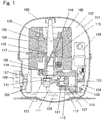
- Fig. 1 is a schematic sectional view of a refrigerant compressor 100 according to Embodiment 1.
- a refrigerant gas 102 is filled in a sealed container 101 of the refrigerant compressor 100, and lubricating oil 103 is stored in a bottom portion of the sealed container 101.
- a hydrocarbon refrigerant is used as the refrigerant gas 102
- a mixed oil constituted by at least mineral oil and synthetic oil is used as the lubricating oil 103.
- An electric element 106 and a compression element 107 are accommodated in the sealed container 101.
- the electric element 106 is constituted by a stator 104 and a rotor 105.
- the compression element 107 is a reciprocating type driven by the electric element 106.
- the compression element 107 is constituted by a crank shaft 108, a cylinder block 112, a piston 115, and the like.
- the configuration of the compression element 107 will be described below.
- the crank shaft 108 is constituted by at least a main shaft 109 and an eccentric shaft 110.
- the main shaft 109 is press-fitted and fixed to the rotor 105.
- the eccentric shaft 110 is formed eccentrically with respect to the main shaft 109.
- An oil supply pump 111 communicating with the lubricating oil 103 is provided at a lower end of the crank shaft 108.
- the cylinder block 112 is made of cast iron.
- the cylinder block 112 forms a substantially cylindrical bore 113 and includes a bearing 114 supporting the main shaft 109.
- the rotor 105 includes a flange surface 116, and an upper end surface of the bearing 114 is a thrust surface 117.
- a thrust washer 118 is inserted between the flange surface 116 and the thrust surface 117 of the bearing 114.
- the flange surface 116, the thrust surface 117, and the thrust washer 118 constitute a thrust bearing 119.
- the piston 115 is loosely fitted into the bore 113 with a certain amount of clearance and is made of an iron-based material.
- the piston 115 forms a compression chamber 120 together with the bore 113.
- the piston 115 is coupled to the eccentric shaft 110 by a connecting rod 122 as a coupler through a piston pin 121.
- An end surface of the bore 113 is sealed by a valve plate 123.
- a head 124 forms a high pressure chamber.
- the head 124 is fixed to the valve plate 123 at an opposite side of the bore 113.
- a suction tube (not shown) is fixed to the sealed container 101 and connected to a low-pressure side (not shown) of a refrigeration cycle. The suction tube introduces the refrigerant gas 102 into the sealed container 101.
- a suction muffler 125 is sandwiched between the valve plate 123 and the head 124.
- a cluster 127 is connected through a lead wire 126 to the stator 104 constituting the electric element 106.
- a terminal 128 is provided at the sealed container 101 so as to penetrate the sealed container 101 from inside to outside.
- the cluster 127 is coupled to the terminal 128. With this, electric power is supplied from a commercial power supply (not shown) to the electric element 106.
- the type of the refrigerant gas 102 used in the refrigerant compressor 100 according to the present disclosure is not especially limited, but the above-described hydrocarbon refrigerant is preferably used.
- Specific examples of the hydrocarbon refrigerant include R290 (propane), R600a (isobutane), R600 (butane), and R1270 (propylene), but the hydrocarbon refrigerant is not especially limited.
- Typical examples of the hydrocarbon refrigerant include R600a and R290.
- the refrigerant compressor 100 uses the lubricating oil 103 having low viscosity and a high flash point.
- the lubricating oil 103 is the mixed oil constituted by the mineral oil and the synthetic oil.
- the refrigerant gas 102 is used in a refrigerant circuit (refrigeration cycle; see Embodiment 2) including the refrigerant compressor 100.
- the refrigerant gas 102 and the lubricating oil 103 exist in the sealed container 101 in a state where the refrigerant gas 102 and the lubricating oil 103 can contact and be mixed with each other.
- the refrigerant gas 102 and the lubricating oil 103 can be regarded as constituting a working medium for the refrigeration cycle.
- the working medium for the refrigeration cycle contains a refrigerant component and a lubricating oil component and may further contain other components.
- resin members are included as members accommodated in the sealed container 101.
- the resin members are not especially limited as long as the resin members are constituted by at least resin, i.e., polymer.
- Typical examples of the resin members include the suction muffler 125, an insulating member attached to the electric element 106, and the cluster 127.
- These resin members may be constituted only by resin (polymer). However, for example, the resin members may be constituted by composite materials containing a different material, such as a fibrous material or a filler, in addition to the resin.
- the cluster 127 is, for example, a member made of polyester resin containing glass fibers.
- the suction muffler 125 is, for example, a member made of polyester resin containing glass fibers.
- the resin (polymer) constituting the resin member is not especially limited.
- Specific examples of the resin (polymer) include polyester resin (such as polyethylene terephthalate (PET) and polybutylene terephthalate (PBT)), polyamide (PA), polyphenylene sulfide (PPS), and liquid crystal polymer (liquid crystal polyester (LCP)). Since such resin excels in heat resistance, refrigerant resistance, oil resistance, and the like, such resin is preferably used as the material of the resin member accommodated in the sealed container 101.
- the resin material constituting the resin member is only required to be one type of resin but may be a polymer alloy (polymer blend) prepared by suitably combining two or more types of resin. Further, a known additive may be contained in the resin constituting the resin member.
- examples of the different material contained in the resin member include the fibrous material and the filler.
- the fibrous material include an aramid fiber, a nylon fiber, a polyester fiber, a glass fiber, and a carbon fiber.
- the fibrous material is not especially limited. Only one type of fibrous material may be used, or two or more types of fibrous materials may be used suitably in combination.
- the filler is only required to be in the form of particles or powder, but may be in the form of short fibers. In some cases, the fibrous material is regarded as the filler.
- Specific examples of the filler include inorganic fillers, such as silica, silicate, clay, plaster, alumina, titanium dioxide, talc, and carbon black. However, the filler is not especially limited.
- the piston 115 reciprocates in the bore 113, and with this, the refrigerant gas 102 introduced into the sealed container 101 through the suction tube (not shown) is sucked from the suction muffler 125 and compressed in the compression chamber 120.
- the lubricating oil 103 is supplied from the oil supply pump 111 to respective slide portions.
- the slide portions are lubricated, and the lubricating oil 103 serves as a seal between the piston 115 and the bore 113.
- the lubricating oil 103 used in the refrigerant compressor 100 is the mixed oil constituted by at least the mineral oil and the synthetic oil.
- the kinetic viscosity of the lubricating oil 103 (mixed oil) at 40°C falls within a range of 0.1 to 5.1 mm 2 /s and is relatively lower than that of conventional oil.
- the flash point of the lubricating oil 103 is 110°C or more.
- the lubricating oil 103 according to the present disclosure contains the mineral oil as a major component and the synthetic oil as a subcomponent and may contain other components. Therefore, the lubricating oil 103 according to the present disclosure is a lubricating oil composition containing the mineral oil and the synthetic oil.
- the content (content rate) of the mineral oil in the lubricating oil 103 is not especially limited, and the content of the mineral oil in the lubricating oil 103 is only required to be set such that the mineral oil is regarded as the "major component" in the entire lubricating oil 103 (lubricating oil composition).
- the content (content rate) of the synthetic oil in the lubricating oil 103 is not especially limited, and the content of the synthetic oil in the lubricating oil 103 is only required to be set such that: the synthetic oil is regarded as the "subcomponent" in the entire lubricating oil 103 (lubricating oil composition); and the content of the synthetic oil is smaller than the content of the mineral oil.
- the content of the synthetic oil as the subcomponent is only required to fall within, for example, a range of 0.1 to 40.0 wt.%, preferably a range of 1 to 35 wt.%, more preferably a range of 5 to 25 wt.%. Further, the content of the mineral oil as the major component in the lubricating oil 103 is only required to be larger than the content of the synthetic oil.
- the content of the synthetic oil is 40.0 wt.% or less of the entire amount of the lubricating oil 103 as described above
- the content of the mineral oil is only required to exceed 40.0 wt.% of the entire amount of the lubricating oil 103 and may be, for example, 50 wt.% or more.
- the synthetic oil is mixed (blended) with the mineral oil such that the viscosity of the lubricating oil 1 03 is lowered, and in addition, the flash point of the lubricating oil 103 is prevented from lowering. Therefore, when the content of the synthetic oil is set to fall within the above range, the kinetic viscosity of the lubricating oil 103 and a lower limit of the flash point of the lubricating oil 103 can be easily adjusted to fall within the above-described respective numerical ranges.
- the types of the mineral oil and synthetic oil constituting the lubricating oil 103 are not especially limited.
- General examples of the mineral oil include paraffin mineral oil and naphthenic mineral oil.
- the paraffin mineral oil or the naphthenic mineral oil may be used, or a mixture of the paraffin mineral oil and the naphthenic mineral oil may be used.
- plural types of paraffin mineral oils having different physical properties may be used in combination.
- plural types of naphthenic mineral oils having different physical properties may be used in combination.
- a mixture of a combination of different paraffin mineral oils and a combination of different naphthenic mineral oils may be used.
- the synthetic oil examples include polyalphaolefin oil, alkyl benzene oil, ester oil, ether oil, polyalkylene glycol oil, fluorinated synthetic oil, and silicon synthetic oil.
- the synthetic oil is not especially limited. Only one type of synthetic oil may be selected and mixed with the mineral oil, or a combination of plural types of synthetic oils may be mixed with the mineral oil.
- the kinetic viscosity of the lubricating oil 103 and the lower limit of the flash point of the lubricating oil 103 can be easily adjusted to fall within the above-described respective numerical ranges. Further, depending on the type of the synthetic oil, properties other than the kinetic viscosity and the lower limit of the flash point can be given to the lubricating oil 103. For example, when ester oil having polarity is selected as the synthetic oil and mixed with the mineral oil, the polarity can be given to the lubricating oil 103.
- the lubricating oil 103 is manufactured by mixing at least the mineral oil and the synthetic oil with each other. With this, as described above, the kinetic viscosity of the lubricating oil 103 at 40°C is adjusted to fall within a range of 0.1 to 5.1 mm 2 /s, and the flash point of the lubricating oil 103 is adjusted to 110°C or more.
- the kinetic viscosity of the lubricating oil 103 at 40°C is not especially limited as long as it falls within the above range.
- a preferable example is that the kinetic viscosity of the lubricating oil 103 at 40°C falls within a range of 0.1 to 4.5 mm 2 /s, and a more preferable example is that the kinetic viscosity of the lubricating oil 103 at 40°C falls within a range of 0.1 mm 2 /s or more and less than 3.0 mm 2 /s.
- the kinetic viscosity is measured based on JIS K2283.
- the kinetic viscosity of the lubricating oil 103 at 40°C exceeds 5.1 mm 2 /s, this does not mean that the viscosity of the lubricating oil 103 is lowered. Therefore, the effect of the increase in the efficiency by the lowering of the viscosity cannot be adequately obtained. In contrast, if the kinetic viscosity of the lubricating oil 103 at 40°C is less than 0.1 mm 2 /s, the lubricating effect of the lubricating oil 103 may not be adequately obtained.
- the lower limit of the flash point of the lubricating oil 103 is not especially limited as long as it is 110°C or more. However, a preferable example is 120°C or more, and a more preferable example is 150°C or more.
- the flash point is measured based on JIS K2265. If the lower limit of the flash point of the lubricating oil 103 is less than 110°C, more extreme care against fire is required when handling the lubricating oil 103. In addition, if a special storage condition is not satisfied, the viscosity of the lubricating oil 103 may increase over time. Therefore, the handleability of the lubricating oil 103 deteriorates.
- the flash point of the lubricating oil 1 03 lowers, the amount of low distillation components contained in the lubricating oil 103 increases. Therefore, if the lubricating oil 103 is stored under a normal condition, the low distillation components contained in the lubricating oil 103 may evaporate first, and this may increase the viscosity of the lubricating oil 103 over time.
- the general lubricating oil 103 is stored under a low-vacuum and high-temperature condition, such as a 10 -2 Pa atmosphere and a temperature range of 40 to 60°C.
- the lubricating oil 103 in addition to the range of the kinetic viscosity of the lubricating oil 103 at 40°C and the lower limit of the flash point of the lubricating oil 103, a predetermined distillation property be satisfied.
- the lubricating oil 103 according to the present disclosure have a distillation property in which a distillation range is 200 to 400°C (i.e., a distillation property in which an initial boiling point is 200°C, and an end point is 400°C).
- the distillation property is measured based on JIS K2254.
- the mineral oil is basically a mixture of many types of oily substances, the mineral oil has a wide variety of distillation properties.
- the synthetic oil is basically constituted by one type of synthetic compound (or several types of synthetic compounds), one distillation property is specified (or several distillation properties are specified). Therefore, by mixing the synthetic oil with the mineral oil, the distillation property of the lubricating oil 103 that is the mixed oil can be adjusted to fall within the above distillation range. It should be noted that the mineral oil may be refined so as to also fall within the above distillation range according to need.
- the lubricating oil 103 when the lubricating oil 103 satisfies a condition that is the distillation property in addition to basic conditions that are the range of the kinetic viscosity at 40°C and the lower limit of the flash point, the amount of the low distillation components contained in the lubricating oil 103 can be made smaller. Therefore, the tendency of the lowering of the flash point of the lubricating oil 103 can be suppressed more effectively, and the stability of the lubricating oil 103 can be made satisfactory. As a result, the handleability of the lubricating oil 103 can be made more suitable.
- the lubricating oil 103 is the lubricating oil composition constituted by the mineral oil and the synthetic oil and may contain a component other than the mineral oil and the synthetic oil. Specific examples of such component include various additives known in the field of the lubricating oil 1 03.
- the additive is not especially limited but is, for example, at least one of an extreme pressure additive, an oily agent, an antifoaming agent, and a stabilizing agent.
- the amount of the additive added (the content of the additive) is not not especially limited. In the present disclosure, the amount of the additive added is only required to fall within a range of 0.1 to 4.0 wt.% of the entire amount of the lubricating oil 103. If the content of the additive is less than 0.1 wt.% of the entire amount of the lubricating oil 103, the amount of the additive added may be too small, and therefore, the effect of the additive may not be adequately obtained, although it depends on the type of the additive. In contrast, if the content of the additive exceeds 4.0 wt.% of the entire amount of the lubricating oil 103, the effect corresponding to the amount of the additive added may not be obtained, although it depends on the type of the additive. In addition, since the content of the additive is excessive, this may influence other physical properties of the lubricating oil 103.
- a typical example of the additive is the stabilizing agent.
- the stabilizing agent By adding the stabilizing agent, the physical properties of the lubricating oil 103 having the low viscosity and the high flash point can be satisfactorily stabilized.
- examples of the stabilizing agent include an acid capturing agent and fullerene.
- the acid capturing agent is used to prevent a case where the base oil (i.e., the mixed oil constituted by the mineral oil and the synthetic oil) is deteriorated by water or oxygen, and this increases the acid value.
- the base oil i.e., the mixed oil constituted by the mineral oil and the synthetic oil
- the acid capturing agent By suppressing the deterioration of the mixed oil (base oil) by the addition of the acid capturing agent, the kinetic viscosity of the lubricating oil 103 at 40°C can be effectively prevented from falling outside the above range.
- the specific type of the acid capturing agent is not especially limited, and a known acid capturing agent can be suitably used. Since the fullerene has an effect of suppressing the lowering of the flash point of the lubricating oil 103, the fullerene can be used as a "flash point lowering suppressing agent.” Therefore, the lowering of the flash point of the lubricating oil 103 can be further effectively suppressed by the addition of the fullerene.
- the amount of the acid capturing agent and/or fullerene added as the stabilizing agent is only required to fall within a range of 0.1 to 4.0 wt.% of the entire amount of the lubricating oil 103.
- the amount of the stabilizing agent added i.e., the content of the stabilizing agent
- the properties of the lubricating oil 103 can be improved by an appropriate amount of stabilizing agent. Therefore, the reliability of the refrigerant compressor 100 can be further improved.
- the electric element 106, the compression element 107, and the like are accommodated in the sealed container 101, and the lubricating oil 103 is stored in the sealed container 101.
- the lubricating oil 103 is the mixed oil constituted by at least the mineral oil and the synthetic oil.
- the kinetic viscosity of the lubricating oil 103 at 40°C falls within a range of 0.1 to 5.1 mm 2 /s, and the flash point of the lubricating oil 103 is 110°C or more.
- the base oil of the lubricating oil 103 is not the mineral oil but the mixed oil constituted by the mineral oil and the synthetic oil.
- the kinetic viscosity is adjusted to fall within the above range, and the lower limit of the flash point is adjusted to become the above value.
- the lubricating oil 103 having the low viscosity and the high flash point is obtained, and therefore, the deterioration of the handleability of the lubricating oil 103 can be effectively suppressed.
- the efficiency of the refrigerant compressor 100 can be increased.
- the high productivity can be realized.
- the refrigerant compressor 100 is configured such that the electric element 106 is arranged above the compression element 107.
- the refrigerant compressor according to the present disclosure may be configured such that the electric element 106 is arranged under the compression element 107.
- a refrigerant compressor to which the present disclosure is applicable is configured to be able to use the above-described lubricating oil 103, such refrigerant compressor can obtain the same operational advantages as Embodiment 1.
- the refrigerant compressor 100 is the reciprocating type.
- the refrigerant compressor according to the present disclosure is not limited to the reciprocating type and may be a known type, such as a rotary type, a scroll type, or a vibration type.
- a refrigerant compressor to which the present disclosure is applicable is configured to be able to use the above-described lubricating oil 103, such refrigerant compressor can obtain the same operational advantages as Embodiment 1.
- the refrigerant compressor 100 is driven by a commercial power supply.
- the refrigerant compressor according to the present disclosure is not limited to this and may be, for example, inverter-driven at a plurality of driving frequencies. Even when the refrigerant compressor is configured as above, high lubricity can be realized by using the above-described lubricating oil 103. Therefore, the reliability of the refrigerant compressor can be improved even at the time of low-speed driving in which the amount of oil supplied to the respective slide portions becomes small or at the time of high-speed driving in which the rotational frequency of the electric element increases.
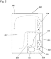
- Embodiment 2 one example of a refrigeration device including the refrigerant compressor 100 described in Embodiment 1 will be specifically described with reference to Fig. 2.
- Fig. 2 schematically shows a schematic configuration of a refrigeration device 200 including the refrigerant compressor 100 according to Embodiment 1. Therefore, Embodiment 2 schematically describes a basic configuration of the refrigeration device 200. However, needless to say, the specific configuration of the refrigeration device 200 is not limited to this.
- the refrigeration device 200 includes a main body 206, a partition wall 209, a refrigerant circuit 201 (refrigeration cycle), and the like.
- the main body 206 is constituted by a heat-insulation box body, a door body, and the like.
- the box body includes an opening on one surface thereof, and the door body opens and closes the opening of the box body.
- the inside of the main body 206 is divided by the partition wall 209 into a storage space 207 for articles and a machine room 208.
- a blower (not shown) is provided in the storage space 207. It should be noted that the inside of the main body 206 may be divided into, for example, spaces other than the storage space 207 and the machine room 208.
- the refrigerant circuit 201 (refrigeration cycle) is configured to cool the inside of the storage space 207 and includes, for example, the refrigerant compressor 100 described in Embodiment 1, a heat radiator 202, a decompressor 203, and a heat absorber 204.
- the refrigerant compressor 100, the heat radiator 202, the decompressor 203, and the heat absorber 204 are annularly connected to one another by a pipe 205.
- the heat absorber 204 is arranged inside the storage space 207. As shown by broken line arrows in Fig. 2 , cooling heat of the heat absorber 204 is stirred by the blower (not shown) so as to circulate in the storage space 207. With this, the inside of the storage space 207 is cooled.
- the refrigeration device 200 according to Embodiment 2 includes the refrigerant circuit 201 including the refrigerant compressor 100 according to Embodiment 1. As described in Embodiment 1, the efficiency of the refrigerant compressor 100 is increased by using the lubricating oil 103 having the low viscosity and the high flash point. Therefore, the refrigeration device 200 according to Embodiment 2 can reduce power consumption. On this account, energy saving can be realized, and reliability can be improved.
- the refrigeration device 200 described in Embodiment 2 is one example of the refrigeration device according to the present disclosure (i.e., the refrigeration device including the refrigerant compressor according to the present disclosure). Needless to say, the present disclosure is not limited to the refrigeration device 200. Examples of the refrigeration device according to the present disclosure include refrigerators (home use, business use), dehumidifiers, showcases, ice makers, heat pump water heaters, heat pump washing/drying machines, vending machines, and air conditioners.
- the present invention is widely and suitably applicable to the field of refrigerant compressors using lubricating oil having low viscosity and refrigeration device s including such refrigerant compressors.
Landscapes
- Chemical & Material Sciences (AREA)
- Engineering & Computer Science (AREA)
- Oil, Petroleum & Natural Gas (AREA)
- Organic Chemistry (AREA)
- Chemical Kinetics & Catalysis (AREA)
- General Chemical & Material Sciences (AREA)
- General Engineering & Computer Science (AREA)
- Mechanical Engineering (AREA)
- Health & Medical Sciences (AREA)
- Emergency Medicine (AREA)
- Thermal Sciences (AREA)
- Physics & Mathematics (AREA)
- Lubricants (AREA)
- Compressor (AREA)
Applications Claiming Priority (2)
| Application Number | Priority Date | Filing Date | Title |
|---|---|---|---|
| JP2017089973 | 2017-04-28 | ||
| PCT/JP2018/016908 WO2018199204A1 (fr) | 2017-04-28 | 2018-04-26 | Compresseur frigorifique hermétiquement scellé et dispositif frigorifique utilisant ledit compresseur |
Publications (2)
| Publication Number | Publication Date |
|---|---|
| EP3617504A1 true EP3617504A1 (fr) | 2020-03-04 |
| EP3617504A4 EP3617504A4 (fr) | 2020-04-22 |
Family
ID=63919157
Family Applications (1)
| Application Number | Title | Priority Date | Filing Date |
|---|---|---|---|
| EP18791980.8A Withdrawn EP3617504A4 (fr) | 2017-04-28 | 2018-04-26 | Compresseur frigorifique hermétiquement scellé et dispositif frigorifique utilisant ledit compresseur |
Country Status (5)
| Country | Link |
|---|---|
| US (1) | US20200141616A1 (fr) |
| EP (1) | EP3617504A4 (fr) |
| JP (2) | JPWO2018199204A1 (fr) |
| CN (1) | CN110573734A (fr) |
| WO (1) | WO2018199204A1 (fr) |
Families Citing this family (1)
| Publication number | Priority date | Publication date | Assignee | Title |
|---|---|---|---|---|
| WO2018199204A1 (fr) * | 2017-04-28 | 2018-11-01 | パナソニック アプライアンシズ リフリジレーション デヴァイシズ シンガポール | Compresseur frigorifique hermétiquement scellé et dispositif frigorifique utilisant ledit compresseur |
Family Cites Families (25)
| Publication number | Priority date | Publication date | Assignee | Title |
|---|---|---|---|---|
| US20050096246A1 (en) * | 2003-11-04 | 2005-05-05 | Johnson Robert C. | Solvent compositions containing chlorofluoroolefins |
| JP2004092509A (ja) * | 2002-08-30 | 2004-03-25 | Toshiba Kyaria Kk | 往復式密閉型圧縮機 |
| JP5330631B2 (ja) * | 2004-01-30 | 2013-10-30 | 出光興産株式会社 | 潤滑油組成物 |
| JP4961666B2 (ja) | 2004-12-02 | 2012-06-27 | 日油株式会社 | 冷凍機用潤滑油組成物 |
| JP5180437B2 (ja) * | 2005-01-07 | 2013-04-10 | Jx日鉱日石エネルギー株式会社 | 潤滑油基油 |
| JP4806967B2 (ja) | 2005-05-27 | 2011-11-02 | 日油株式会社 | 冷凍機用潤滑油組成物 |
| JP5122740B2 (ja) * | 2005-11-15 | 2013-01-16 | 出光興産株式会社 | 冷凍機油組成物 |
| JP5352053B2 (ja) * | 2007-01-23 | 2013-11-27 | 出光興産株式会社 | 油冷式スクリュー空気圧縮機用潤滑油組成物およびこれを充填した油冷式スクリュー空気圧縮機 |
| CN101970624A (zh) * | 2007-11-22 | 2011-02-09 | 出光兴产株式会社 | 冷冻机用润滑油组合物及使用该组合物的压缩机 |
| JP5325469B2 (ja) * | 2008-06-11 | 2013-10-23 | 出光興産株式会社 | 潤滑油組成物 |
| JP5326525B2 (ja) * | 2008-11-28 | 2013-10-30 | パナソニック株式会社 | 圧縮機 |
| JP2010249391A (ja) * | 2009-04-15 | 2010-11-04 | Panasonic Corp | 摺動部材と密閉型圧縮機および冷凍サイクル装置 |
| JP5222244B2 (ja) | 2009-07-15 | 2013-06-26 | 日立アプライアンス株式会社 | 往復圧縮機 |
| JP2012097638A (ja) * | 2010-11-01 | 2012-05-24 | Daikin Industries Ltd | 圧縮機および冷凍装置 |
| CN104145008B (zh) * | 2012-03-02 | 2016-05-04 | 吉坤日矿日石能源株式会社 | 冷冻机用工作流体组合物、冷冻机油以及其制造方法 |
| JP6195429B2 (ja) * | 2012-03-29 | 2017-09-13 | Jxtgエネルギー株式会社 | 冷凍機用作動流体組成物及び冷凍機油 |
| JP5937446B2 (ja) * | 2012-07-13 | 2016-06-22 | Jxエネルギー株式会社 | 冷凍機用作動流体組成物 |
| JP6126377B2 (ja) * | 2012-12-26 | 2017-05-10 | 昭和シェル石油株式会社 | 油類又は油類組成物の引火点向上方法及び引火点向上油性組成物 |
| JP6209731B2 (ja) * | 2013-03-27 | 2017-10-11 | パナソニックIpマネジメント株式会社 | 密閉型圧縮機 |
| CN104087388A (zh) * | 2014-07-22 | 2014-10-08 | 瑞孚化工(上海)有限公司 | 一种冷冻机油组合物及其应用 |
| JP2016193994A (ja) * | 2015-03-31 | 2016-11-17 | 出光興産株式会社 | 潤滑油組成物、及び潤滑油組成物の製造方法 |
| JP2016190918A (ja) * | 2015-03-31 | 2016-11-10 | Jxエネルギー株式会社 | 潤滑油組成物 |
| JP6826987B2 (ja) * | 2015-09-29 | 2021-02-10 | Khネオケム株式会社 | 冷凍機油組成物およびそれを用いた冷凍機用作動流体組成物 |
| JP6059320B2 (ja) * | 2015-10-30 | 2017-01-11 | Jxエネルギー株式会社 | 冷凍機用作動流体組成物及び冷凍機油 |
| WO2018199204A1 (fr) * | 2017-04-28 | 2018-11-01 | パナソニック アプライアンシズ リフリジレーション デヴァイシズ シンガポール | Compresseur frigorifique hermétiquement scellé et dispositif frigorifique utilisant ledit compresseur |
-
2018
- 2018-04-26 WO PCT/JP2018/016908 patent/WO2018199204A1/fr not_active Ceased
- 2018-04-26 JP JP2019514597A patent/JPWO2018199204A1/ja active Pending
- 2018-04-26 CN CN201880028242.8A patent/CN110573734A/zh active Pending
- 2018-04-26 US US16/609,023 patent/US20200141616A1/en not_active Abandoned
- 2018-04-26 EP EP18791980.8A patent/EP3617504A4/fr not_active Withdrawn
-
2021
- 2021-01-20 JP JP2021006990A patent/JP2021080926A/ja active Pending
Also Published As
| Publication number | Publication date |
|---|---|
| WO2018199204A1 (fr) | 2018-11-01 |
| JPWO2018199204A1 (ja) | 2020-03-19 |
| US20200141616A1 (en) | 2020-05-07 |
| CN110573734A (zh) | 2019-12-13 |
| EP3617504A4 (fr) | 2020-04-22 |
| JP2021080926A (ja) | 2021-05-27 |
Similar Documents
| Publication | Publication Date | Title |
|---|---|---|
| KR100339693B1 (ko) | 냉동장치및윤활유조성물 | |
| KR100883532B1 (ko) | 밀폐형 압축기 및 냉동 장치 및 냉장고 | |
| JP5260168B2 (ja) | 冷媒圧縮機 | |
| JP5086782B2 (ja) | 冷媒圧縮機および冷凍サイクル | |
| JP5477455B2 (ja) | 密閉型圧縮機 | |
| JP2021088991A (ja) | 密閉型冷媒圧縮機およびこれを用いた冷凍装置 | |
| JP2008531896A (ja) | 冷媒圧縮機 | |
| JP7348203B2 (ja) | 冷媒圧縮機及びこれを用いた機器 | |
| EP3617504A1 (fr) | Compresseur frigorifique hermétiquement scellé et dispositif frigorifique utilisant ledit compresseur | |
| JP2006509962A (ja) | 冷媒圧縮用往復動式圧縮機 | |
| JP2011111930A (ja) | 冷媒圧縮機と冷媒圧縮機用冷凍機油および冷凍装置 | |
| JP2010255449A (ja) | ロータリー圧縮機 | |
| US20100170291A1 (en) | Hermetic compressor and refrigeration system | |
| JP6922109B2 (ja) | 密閉型冷媒圧縮機およびそれを用いた冷凍・冷蔵装置 | |
| JP2010255448A (ja) | ロータリー圧縮機 | |
| JP2006037826A (ja) | 冷媒圧縮機 | |
| US20200270541A1 (en) | Oxide film formed on surface of base material that is iron-based sintered body, sliding member on which oxide film is formed, and apparatus including sliding member | |
| JP4905464B2 (ja) | 冷媒圧縮機 | |
| CN100376791C (zh) | 致冷剂压缩机 | |
| JP2010031134A (ja) | 冷媒圧縮機 | |
| JP2005133634A (ja) | 冷媒圧縮機 | |
| JP2013011216A (ja) | 冷媒圧縮機 | |
| JP2009281222A (ja) | 多段式圧縮機 | |
| JP2010255481A (ja) | ロータリー圧縮機 | |
| JP2009228621A (ja) | 密閉型圧縮機 |
Legal Events
| Date | Code | Title | Description |
|---|---|---|---|
| STAA | Information on the status of an ep patent application or granted ep patent |
Free format text: STATUS: THE INTERNATIONAL PUBLICATION HAS BEEN MADE |
|
| PUAI | Public reference made under article 153(3) epc to a published international application that has entered the european phase |
Free format text: ORIGINAL CODE: 0009012 |
|
| STAA | Information on the status of an ep patent application or granted ep patent |
Free format text: STATUS: REQUEST FOR EXAMINATION WAS MADE |
|
| 17P | Request for examination filed |
Effective date: 20191015 |
|
| AK | Designated contracting states |
Kind code of ref document: A1 Designated state(s): AL AT BE BG CH CY CZ DE DK EE ES FI FR GB GR HR HU IE IS IT LI LT LU LV MC MK MT NL NO PL PT RO RS SE SI SK SM TR |
|
| AX | Request for extension of the european patent |
Extension state: BA ME |
|
| A4 | Supplementary search report drawn up and despatched |
Effective date: 20200325 |
|
| RIC1 | Information provided on ipc code assigned before grant |
Ipc: F04C 29/02 20060101ALI20200319BHEP Ipc: C10N 20/02 20060101ALI20200319BHEP Ipc: C10N 30/00 20060101ALI20200319BHEP Ipc: C10M 105/18 20060101ALI20200319BHEP Ipc: F04B 39/00 20060101AFI20200319BHEP Ipc: C10M 105/32 20060101ALI20200319BHEP Ipc: C10N 40/30 20060101ALI20200319BHEP Ipc: F04B 39/02 20060101ALI20200319BHEP Ipc: F04B 35/04 20060101ALI20200319BHEP Ipc: C10N 30/02 20060101ALI20200319BHEP Ipc: C10M 101/02 20060101ALI20200319BHEP Ipc: C10M 105/06 20060101ALI20200319BHEP Ipc: C10M 107/34 20060101ALI20200319BHEP Ipc: C10N 20/00 20060101ALI20200319BHEP |
|
| DAV | Request for validation of the european patent (deleted) | ||
| DAX | Request for extension of the european patent (deleted) | ||
| STAA | Information on the status of an ep patent application or granted ep patent |
Free format text: STATUS: THE APPLICATION IS DEEMED TO BE WITHDRAWN |
|
| 18D | Application deemed to be withdrawn |
Effective date: 20221101 |