EP3617545A1 - Montage réduisant les vibrations - Google Patents
Montage réduisant les vibrations Download PDFInfo
- Publication number
- EP3617545A1 EP3617545A1 EP18191610.7A EP18191610A EP3617545A1 EP 3617545 A1 EP3617545 A1 EP 3617545A1 EP 18191610 A EP18191610 A EP 18191610A EP 3617545 A1 EP3617545 A1 EP 3617545A1
- Authority
- EP
- European Patent Office
- Prior art keywords
- last
- limb
- mounting portion
- mounting
- limb section
- Prior art date
- Legal status (The legal status is an assumption and is not a legal conclusion. Google has not performed a legal analysis and makes no representation as to the accuracy of the status listed.)
- Withdrawn
Links
- 235000013353 coffee beverage Nutrition 0.000 claims description 24
- XLYOFNOQVPJJNP-UHFFFAOYSA-N water Substances O XLYOFNOQVPJJNP-UHFFFAOYSA-N 0.000 claims description 18
- 230000001939 inductive effect Effects 0.000 claims description 11
- 238000013461 design Methods 0.000 description 25
- 238000005452 bending Methods 0.000 description 13
- 238000002955 isolation Methods 0.000 description 9
- 238000013016 damping Methods 0.000 description 6
- 230000001965 increasing effect Effects 0.000 description 6
- 230000008901 benefit Effects 0.000 description 5
- 230000006835 compression Effects 0.000 description 5
- 238000007906 compression Methods 0.000 description 5
- 230000009467 reduction Effects 0.000 description 5
- 230000005540 biological transmission Effects 0.000 description 4
- 230000000694 effects Effects 0.000 description 4
- 230000015572 biosynthetic process Effects 0.000 description 3
- 238000005755 formation reaction Methods 0.000 description 3
- 239000000463 material Substances 0.000 description 3
- 238000000034 method Methods 0.000 description 3
- XEEYBQQBJWHFJM-UHFFFAOYSA-N Iron Chemical compound [Fe] XEEYBQQBJWHFJM-UHFFFAOYSA-N 0.000 description 2
- 238000013459 approach Methods 0.000 description 2
- 239000002775 capsule Substances 0.000 description 2
- 230000008859 change Effects 0.000 description 2
- 230000001419 dependent effect Effects 0.000 description 2
- 230000007246 mechanism Effects 0.000 description 2
- 238000005086 pumping Methods 0.000 description 2
- 241000533293 Sesbania emerus Species 0.000 description 1
- 229910000639 Spring steel Inorganic materials 0.000 description 1
- 230000003321 amplification Effects 0.000 description 1
- 230000009286 beneficial effect Effects 0.000 description 1
- 235000015114 espresso Nutrition 0.000 description 1
- 230000005484 gravity Effects 0.000 description 1
- 238000003780 insertion Methods 0.000 description 1
- 230000037431 insertion Effects 0.000 description 1
- 238000011835 investigation Methods 0.000 description 1
- 229910052742 iron Inorganic materials 0.000 description 1
- 238000003199 nucleic acid amplification method Methods 0.000 description 1
- 230000010363 phase shift Effects 0.000 description 1
- 230000021715 photosynthesis, light harvesting Effects 0.000 description 1
- 238000006748 scratching Methods 0.000 description 1
- 230000002393 scratching effect Effects 0.000 description 1
- 230000011218 segmentation Effects 0.000 description 1
- 239000007787 solid Substances 0.000 description 1
- 239000000725 suspension Substances 0.000 description 1
- 239000003190 viscoelastic substance Substances 0.000 description 1
- 238000004804 winding Methods 0.000 description 1
Images





Classifications
-
- F—MECHANICAL ENGINEERING; LIGHTING; HEATING; WEAPONS; BLASTING
- F16—ENGINEERING ELEMENTS AND UNITS; GENERAL MEASURES FOR PRODUCING AND MAINTAINING EFFECTIVE FUNCTIONING OF MACHINES OR INSTALLATIONS; THERMAL INSULATION IN GENERAL
- F16F—SPRINGS; SHOCK-ABSORBERS; MEANS FOR DAMPING VIBRATION
- F16F1/00—Springs
- F16F1/02—Springs made of steel or other material having low internal friction; Wound, torsion, leaf, cup, ring or the like springs, the material of the spring not being relevant
- F16F1/025—Springs made of steel or other material having low internal friction; Wound, torsion, leaf, cup, ring or the like springs, the material of the spring not being relevant characterised by having a particular shape
-
- A—HUMAN NECESSITIES
- A47—FURNITURE; DOMESTIC ARTICLES OR APPLIANCES; COFFEE MILLS; SPICE MILLS; SUCTION CLEANERS IN GENERAL
- A47J—KITCHEN EQUIPMENT; COFFEE MILLS; SPICE MILLS; APPARATUS FOR MAKING BEVERAGES
- A47J31/00—Apparatus for making beverages
- A47J31/44—Parts or details or accessories of beverage-making apparatus
- A47J31/46—Dispensing spouts, pumps, drain valves or like liquid transporting devices
- A47J31/468—Pumping means
-
- F—MECHANICAL ENGINEERING; LIGHTING; HEATING; WEAPONS; BLASTING
- F16—ENGINEERING ELEMENTS AND UNITS; GENERAL MEASURES FOR PRODUCING AND MAINTAINING EFFECTIVE FUNCTIONING OF MACHINES OR INSTALLATIONS; THERMAL INSULATION IN GENERAL
- F16F—SPRINGS; SHOCK-ABSORBERS; MEANS FOR DAMPING VIBRATION
- F16F15/00—Suppression of vibrations in systems; Means or arrangements for avoiding or reducing out-of-balance forces, e.g. due to motion
- F16F15/02—Suppression of vibrations of non-rotating, e.g. reciprocating systems; Suppression of vibrations of rotating systems by use of members not moving with the rotating systems
- F16F15/04—Suppression of vibrations of non-rotating, e.g. reciprocating systems; Suppression of vibrations of rotating systems by use of members not moving with the rotating systems using elastic means
- F16F15/06—Suppression of vibrations of non-rotating, e.g. reciprocating systems; Suppression of vibrations of rotating systems by use of members not moving with the rotating systems using elastic means with metal springs
-
- A—HUMAN NECESSITIES
- A47—FURNITURE; DOMESTIC ARTICLES OR APPLIANCES; COFFEE MILLS; SPICE MILLS; SUCTION CLEANERS IN GENERAL
- A47J—KITCHEN EQUIPMENT; COFFEE MILLS; SPICE MILLS; APPARATUS FOR MAKING BEVERAGES
- A47J31/00—Apparatus for making beverages
- A47J31/44—Parts or details or accessories of beverage-making apparatus
- A47J31/4403—Constructional details
-
- F—MECHANICAL ENGINEERING; LIGHTING; HEATING; WEAPONS; BLASTING
- F16—ENGINEERING ELEMENTS AND UNITS; GENERAL MEASURES FOR PRODUCING AND MAINTAINING EFFECTIVE FUNCTIONING OF MACHINES OR INSTALLATIONS; THERMAL INSULATION IN GENERAL
- F16F—SPRINGS; SHOCK-ABSORBERS; MEANS FOR DAMPING VIBRATION
- F16F2236/00—Mode of stressing of basic spring or damper elements or devices incorporating such elements
- F16F2236/08—Torsion
Definitions
- This invention relates to a mounting device for mounting a component which suffers from vibration, and which aims to dampen those vibrations.
- a suspension mounting between a vibration source such as a motor or pump and the rest of the device to reduce vibration transmission, by isolating the vibrations from the rest of the device or damping the vibrations (i.e. dissipating their energy).
- the aim is to avoid the vibrations being transferred to the outside of the device, e.g. the outer casing, which is undesirable. There is also a desire to avoid wear and noise through rattling. Certain noise components may also be particularly disturbing to users of an apparatus.
- the most commonly used approach is a mass-spring mechanism, providing vibration reduction and vibration isolation (for example by making use of a 180 degree phase shift).
- Many different spring designs are known that provide vibration reduction and isolation.
- a wire coil spring is probably the most commonly used version.
- the spring may be formed as a compression spring, tension spring or torsion spring.
- a pump or motor may be mounted vertically on top of a compression spring.
- a pump or motor operated by the mains operates at 50 or 60 Hz and this is accordingly the main frequency at which vibrations may arise.
- a spring design is desired with a low spring constant and low amount of damping.
- a low amount of damping is desirable because this corresponds to a low dissipation of energy.
- a high damping for example based on a spring combined with a viscoelastic material, means that part of the movement velocity of the component (e.g. pump or motor) is partially translated into deformation in the damping material as well as the deformation of the spring. Since the deformation expends a certain amount of energy, less energy is available for resonance. In many applications, the vibration reduction method is used to reduce the vibration amplitude at resonance.
- vibration energy dissipation via damping should be prevented, instead for optimal vibration cancellation, the vibration energy should be equal but opposite in direction with the rebound energy.
- Standard compression, tension and torsion coil springs have several disadvantages relating to the dynamics and acoustics.
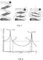
- Figure 1 shows a compression coil spring in a relaxed state (left image) and in a compressed state (right two images).
- the coils start to move and can touch each other as shown in the right two images in Figure 1 .
- the coils at the ends can touch (middle image) or the middle coils can touch (right image).
- the coils may also rub or scrape along other device parts generating additional noise.
- this effect can be reduced by increasing the pitch, but at the ends (the start and end windings), this is often not possible.
- volume restrictions do not always allow such an increase in pitch.
- the low spring constant of a coil spring is achieved by using multiple coils (so called “active coils”), that provide a large wire length compared to the thickness (L>>d).
- active coils multiple coils
- the low spring constant of the spring coupled to the component (motor or pump) mass results in a low system resonance frequency. Due to the relatively long but thin wire, the fundamental Eigen frequency (the first bending mode at the resonance frequency) of the spring itself is low as well.
- the result is a narrow effective operating range (frequency window) in which there is vibration reduction, free of resonances. This is illustrated in Figure 2 , showing a plot of vibration transmission T (y-axis) as a function of angular speed ⁇ (x-axis, rad/sec).
- the value T is a measure of the amount of vibration found at the base (which should not vibrate) compared to the vibration of the vibration source.
- a value 0 indicates no difference between the base and the vibration source.
- a value >0 means amplification at the base compared to the source (i.e. resonance).
- a value ⁇ 0 means vibration isolation.
- Peak 10 is a resonance peak (i.e. resonant frequency) of the mass spring system at frequency fn_sys.
- Crossing point 12 is at the frequency fn_sys * ⁇ 2. This is the frequency at which vibration isolation starts.
- Peak 14 is a resonance peak (i.e. resonant frequency) of the spring itself at frequency fn_local.
- Crossing point 16 is at the frequency fn_local / ⁇ 2. This is the frequency at which vibration isolation ends.
- f_eff is the effective operating frequency window.
- a coil spring consists of a long continuous curve with large radius of curvature, which does not provide additional rigidity for the wire against bending.
- the relatively long wire length is also not beneficial regarding optimal use of material and material cost. This length also means that the wire contains many local resonance modes, namely wire bending modes at specific frequencies, leading to reduced vibration isolation performance and other acoustic effects.
- a vibration reducing mounting comprising a wire, which follows a path, which comprises:
- This mounting makes use of a wire structure, forming an inner mounting portion and an outer support portion. This enables a structure with a low profile in that the outer support portion is around the inner mounting portion.
- the support plane of the outer support portion is parallel to the first plane of the mounting portion.
- the bends enable the wire to have a relatively short length (e.g. compared to a multiple coil spring), and this means the local resonance modes are shifted to higher frequencies which increases the effective operating range for vibration isolation.
- the bends increase the local bending stiffness but maintain the overall spring constant of the mounting.
- each of the bends of the first and second sequences has an angle of 150 degrees or less.
- parallel is intended to cover minor deviations from parallel.
- the term parallel may be taken to mean at an angle of 5 degrees or less.
- the mounting may be formed as a single wire.
- the wire may for example be made of spring steel, and may have a diameter (or more generally a maximum linear dimension for example with a non-circular cross section) in the range of 0.5mm to 4mm, for example 0.5mm to 2mm, such as 1mm.
- the sequences of bends are located in a section of the mounting between the mounting portion and the support plane.
- the first and second planes may be offset from each other.
- the offset between the first and second planes is caused by the sequences of bends, and it means bending stiffness is provided in more than one plane.
- the mounting portion may comprise an open loop, the ends of the open loop defining the one end and the opposite end of the mounting portion.
- the open loop may for example be clipped around a channel of the component to be mounted. This may be achieved by flexing open the open part of the loop, fitting the loop around the channel, and allowing the loop to close around the channel. This provides an easy to fit structure, in the form of a spring clip.
- the first limb mounting portion and the second limb mounting portion may each comprise a hook.
- Each hook for example comprises a wire portion after a 90 degree bend.
- the hooks can be fitted into receiving portions of a support structure which is to support the component to be mounted.
- Each of the bends in the sequences of bends may have a bend radius less than or equal to 10 times the diameter (or more generally maximum dimension in cross section) of the wire.
- the bends are thus tight bends rather than gradual curvature in the wire. These sharp bends increase the bending stiffness.
- the one end of the mounting portion is for example at one side of the mounting portion, and the other end of the mounting portion is at an opposite side of the mounting portion, wherein the mounting portion is side-side symmetrical.
- the limbs extend outwardly from opposite sides of the mounting portion.
- the overall structure may be side-side symmetrical.
- the last first limb section and the last second limb section may be at an angle of less than 30 degrees to each other. Thus, they form two parallel or near parallel lines on opposite sides of the mounting portion, and thereby form a balanced support structure.
- the last first limb section and the last second limb section may each have a length greater than the maximum linear dimension of the mounting portion.
- the support plane as defined by the last first limb section and the last second limb section can thus extend over a large area, extending beyond the projection of the mounting portion.
- Such support plane may provide vibration reduction of off-axis vibrations as well as axial vibration (wherein the axis may be defined as perpendicular to the first and second planes).
- the first and second sequences each comprise exactly two bends and wherein the first first limb section and the first second limb section are collinear and extend outwardly from opposite sides of the mounting portion.
- the first and second sequences each comprise exactly four bends, wherein the first first limb section and the last first limb section are at an angle of between 0 and 30 degrees and wherein the first second limb section and the last second limb section are at an angle of between 0 and 30 degrees.
- first first limb section and the first second limb section may for example be parallel and side by side and lie in the first plane.
- the invention also provides a system comprising:
- the vibration inducing component is for example mounted vertically, such that the first plane and the second plane are horizontal.
- the vibration inducing component may comprise a pump or motor.
- the invention also provides a coffee machine comprising:
- the invention provides a vibration reducing mounting comprising a wire which follows a path which comprises a mounting portion for fixing to a component to be mounted in a first plane and first and second limbs extending outwardly from the mounting portion.
- Each limb has a sequence of bends and the end sections lie in a second plane parallel with the first plane and which functions as a support plane.
- the end sections extend across opposite sides of the mounting portion. At least one of the bends and preferably each bend of the bend sequences has an angle of 150 degrees or less.
- Figure 3 shows how the required wire length (x-axis, mm) depends on the wire diameter (y-axis, mm) to achieve a given spring constant (here: 10kN/m) for different designs (here: straight or coiled, coil number, coil diameter).
- Plot 30 is for a straight wire.
- Plot 32 is for a coil spring having a single coil and plot 34 is for a coil spring having five coils. The different points in the respective plots 32, 34 correspond to different coil diameters.
- Plot 36 is for a coil spring and the different points correspond to different numbers of coils.
- Figure 3 thus generally shows that, for a given fixed spring constant (in this case 10kN/m), a straight wire requires (in most cases) much smaller wire length than different variants of coil-shaped wire springs.
- a straight wire requires (in most cases) much smaller wire length than different variants of coil-shaped wire springs.
- the shorter the free (unsupported) wire length the higher the local or first natural bending mode frequency fn_local. The shorter length would therefore be preferred since the shorter unsupported wire length would normally also result in a higher first natural bending frequency fn local (cf. peak 14 in Figure 2 ).
- wire length is not the only discriminating factor regarding the frequency fn_local, since wire thickness also plays an important role.
- Figure 4 shows the first natural frequency fn_local (y-axis, Hz) of a spring wire depending on the spring design.
- the x-axis shows the required wire volume (m 3 ).
- Plot 40 is for a straight wire spring, simply supported at both ends, to achieve a spring constant of 1kN/m.
- the overlapping plots 42 are for different coil spring designs and a straight wire design to achieve a spring constant of 10kN/m.
- the area 44 is for the straight wire design.
- the straight wire spring design provides a higher local bending mode frequency fn_local (cf. peak 14 in Figure 2 ).
- the invention makes use of sharp bends along the length of the wire. This provides segmentation of the wire into segments between the bends, and the local bending frequency fn_local, can be increased dramatically.
- Plot 46 shows the results for examples of wires with 1 and 2 bends, simply supported at both ends.
- Figure 5 shows these wire designs.
- the top image shows a straight wire
- the middle image shows a wire with one bend in the middle with angle ⁇ and angle ⁇ at the two simply supported ends
- the bottom image shows a wire with two bends in the middle each with angle ⁇ , and angle ⁇ at the two simply supported ends.
- the two bend angles ⁇ do not have to be equal.
- the bend angle ⁇ is with reference to the horizontal.
- the horizontal distance between the two support points may be considered to be an effective length L_eff.
- Figure 6 shows a plot of the first natural frequency fn_local (y-axis, Hz, logarithmic scale) i.e. the peak 14 in Figure 2 versus the bend angle ⁇ (x-axis, degrees) for a fixed effective wire length and diameter.
- Plot 60 is for one bend and plot 62 is for two bends (wire diameter 1mm, length 10cm).
- Figure 6 shows that the smaller the bend angle ⁇ , the higher the first resonance frequency fn local becomes.
- Figure 7 shows the effect of plotting the data from Figure 6 , but with the ratio L_effective / L_wire (as the x-axis, dimensionless) instead of the bend angles.
- the point 70 is a reference with no bend.
- the first resonance frequency fn_local increases as the ratio is reduced.
- the ratio L_effective / L_wire needs to be reduced to approximately 90%.
- a shift of ⁇ 25% in the value of fn_local would be preferred, meaning that the ratio L_effective / L_wire should be reduced to around at most 85% of the value for a straight wire.
- the increase in resonance frequency fn local is valid for a vertical bending direction as shown in Figure 5 .
- the bends will be in multiple directions.
- Figure 8 shows a first example of a design for a vibration reducing mounting which has been developed based on the findings explained above.
- the vibration reducing mounting 80 comprises a wire 82, which follows a path which comprises a mounting portion MP for fixing to a component to be mounted in a first plane and first L1 and second L2 limbs extending outwardly from the mounting portion.
- Each limb L1, L2 has a sequence of bends. In this example, there are four bends in each limb (after the first bend leading out from the mounting portion and before the final bend leading to a hook at the end of the wire).
- the end sections L1 END and L2 END lie in a second plane parallel with the first plane and which functions as a support plane. The end sections extend across opposite sides of the mounting portion.
- Each of the bends of the bend sequences has an angle of 150 degrees or less. In this example the bends are all in the range 135 to 140 degrees.
- the planes of the mounting portion MP and the end sections are intended to be parallel when the mounting 80 is in a loaded condition, i.e. when the mounting portion is supporting the vibrating component.
- the mounting portion Before supporting the vibrating component, the mounting portion may be non-parallel with the plane of the end portions (which may be considered to be a support plane). For example, with reference to Figure 8 , the top right part of the loop forming the mounting portion (i.e. opposite the opening in the loop) may be elevated. Only when supporting the mass of the vibrating component will the mounting portion bend down against the spring bias of the wire to bring the plane of the mounting portion parallel or near parallel with the support plane.
- the planes are parallel in use, by which is meant when the mounting 80 is in a loaded state.
- the unloaded state there may be an angle of 10 to 40 degrees between the plane of the mounting portion and the support plane.
- the mounting 80 has no wire parts close to each other, which prevents rattling or scratching noises.
- the wire 82 generally has the mounting portion MP in one plane and both ends in another plane (rather than one end at the top and one end at the bottom as is the case for a coil spring).
- each limb L1, L2 defines a 180 degree path from its exit direction from the mounting portion MP to the end of the limb.
- the path of each limb may define at most 270 degrees from the exit from the mounting portion to the end of the limb (in which case the limbs together form one circle around the mounting portion).
- the limbs together define at most one circuit around the mounting portion.
- the mounting portion MP comprises a ring for supporting or attachment to the vibration source, and its plane is at a different height compared to the support plane defined by the end sections L1 END and L2 END .
- An advantage of this is that it provides bending stiffness in other planes, other than only in the horizontal plane.
- Corresponding pairs of limb sections for example each lie in a respective plane, and the planes for the pairs of limb sections are not then parallel with the support plane and the plane of the mounting portion.
- third and further planes may be considered to be defined by the structure.
- the wire would be able to bend easily into the orthogonal plane. This may or may not be desirable, depending on the nature of the vibrations to be isolated. An offset between the two planes is in most cases preferred but it is not essential.
- the first limb L1 comprises a first sequence of bends B1 to B4 between a first first limb section L1S FIRST and a last first limb section L1S LAST (corresponding to L1 END in Fig 8 ), and a first limb mounting portion L1H at the end of the last first limb section L1S LAST .
- LxSy denotes limb number x (1 or 2) and section number y (first through to last) for that limb.
- n th m th limb section denotes the n th section of the m th limb.
- the second limb L2 comprises a second sequence of bends between a first second limb section L2S FIRST and a last second limb section L2S LAST (corresponding to L2 END in Figure 8 ), and a second limb mounting portion L2H at the end of the last second limb section L2S LAST .
- the last limb sections L1S LAST and L2S LAST extend across opposite sides of the mounting portion MP. Thus they form a cradle structure on both sides of the mounting portion MP. At least one bend and preferably each bend is sufficiently tight (with an angle of 150 degrees or less, preferably 140 degrees or less) to influence the rigidity of the structure.
- the offset between the first and second plane is for example in the range 10% to 50% of the maximum linear dimension of the mounting.
- the mounting portion MP comprises an open loop, wherein the ends of the open loop define one end and an opposite end of the mounting portion.
- the limbs L1, L2 may be pulled apart to open the loop further so that it may pass around the vibration source to be held by the mounting portion.
- the vibration source may simply sit on top of the mounting portion under the weight of gravity.
- the first limb mounting portion L1H and the second limb mounting portion L2H each comprise a hook.
- the hook may extend in different directions. In Figure 8 and 9 , the hooks extend perpendicularly to the first and second planes. In an alternative embodiment (see Figures 12 and 13 ) the hooks may extend parallel to the first and second planes.
- the hooks may be used to couple to openings or formations in the housing of the device in which the mounting is to be used.
- the hooks may be biased into those openings, respectively formations.
- the end sections L1S LAST (L1 END ) and L2S LAST (L2 END ) maybe pulled together for insertion into the openings or formations.
- the hooks may function as assembly and alignment features.
- At least one of the bends B1 to B4 and preferably each bend in the sequences of bends is a sharp bend and thus preferably has a bend radius less than or equal to 10 times the diameter of the wire.
- the ends of the mounting portion MP are at opposite sides of a side-side symmetrical shape as shown.
- the first first limb section L1S FIRST and the last first limb section L1S LAST are near parallel, hence at an angle of between 0 and 30 degrees and the first second limb section L2S FIRST and the last second limb section L2S LAST are also near parallel, hence at an angle of between 0 and 30 degrees.
- the limbs thus form a U-shape in plan view.
- the first first limb section L1S FIRST and the first second limb section L2S FIRST may be parallel and side by side, as illustrated.
- the first first limb section L1S FIRST and the first second limb section L2S FIRST may lie in the first plane, as illustrated.
- the last first limb section L1S LAST and the last second limb section L2S LAST may be parallel or near parallel, hence at an angle of less than 30 degrees to each other. They may thus form a pair of supporting rails on opposite sides of the mounting portion MP.
- the last first limb section L1S LAST and the last second limb section L2S LAST may each have a length greater than the maximum linear dimension of the mounting portion MP (i.e. the diameter of the loop).
- One end of each last limb section may be in front of the mounting portion and the other end may be behind the mounting portion.
- the last limb sections can provide a stable base for supporting the mounting portion on a support surface. They may provide support for vibrations which are perpendicular to the first and second planes or offset from that perpendicular direction.
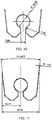
- Figure 10 and 11 show possible dimensions.
- the mounting portion MP comprises a loop of diameter 20mm (e.g. in the range 10mm to 40mm).
- the wire has a diameter 1mm (e.g. in the range 0.5mm to 4mm).
- the first first limb section L1S FIRST and the first second limb section L2S FIRST are spaced by 7mm (generally between 25% and 50% of the maximum dimension of the mounting portion).
- the last first limb section L1S LAST and the last second limb section L2S LAST are at an angle of 11.6 degrees in this example and the maximum overall width is 57.54mm (e.g. in the range 30mm to 100mm).
- the offset between the two planes in this example is 10mm (e.g. in the range 25% to 100% of the maximum dimension of the mounting portion, not referenced in the figures).
- Figures 8 to 11 show an embodiment with four bends per limb.
- Figures 12 and 13 show an embodiment 120 in which the first and second sequences each comprise exactly two bends.
- Figure 12 is a perspective view and Figure 13 is a plan view.
- the first first limb section L1S FIRST and the first second limb section L2S FIRST are collinear and extend outwardly (in opposite directions) from opposite sides of the mounting portion MP.
- the limbs in this design form an L-shape in plan view. Each limb thus has three sections; a first, second and last.
- Figure 14A shows the mounting 120 of Figures 12 and 13 clipped to a base part 140 of a pump.
- the pump is one example of a possible vibration inducing component.
- Figure 14B shows the mounting 80 of Figures 8 and 9 mounted on a pump support bracket 142 but supported loosely rather than being clipped to the base part of the pump.
- the upward tilt of the mounting portion can be seen, because the mounting is not yet supporting the weight of the pump.
- the mounting portion When fully installed, the mounting portion is bent down to lie in a plane parallel with the support plane, i.e. parallel with the last limb sections.
- the base part 140 of the pump may sit beneath the mounting 80, and the mounting 80 is attached to the pump by clamping between the base part 140 of the pump and the main pump body.
- Figure 15A shows a complete pump assembly 150 in which the base part 140 has the mounting 120 of the type shown in Figures 12 and 13 .
- Figure 15B shows a complete pump assembly 150 in which the mounting 80 of the type shown in Figures 8 and 9 is clamped between the base part 140 of the pump and the main pump body.
- Figure 16A shows the pump assembly 150 of Figure 15A mounted in a coffee machine
- Figure 16B shows the pump assembly 150 of Figure 15B mounted in a coffee machine.
- the internal parts of the coffee machine define a support surface 160 on which the last sections L1S LAST and L2S LAST rest.
- the mounting 80, 120 is held to the support structure (of which the surface 160 is part) by the hooks L1H, L2H.
- the support surface 160 provides support for downward movement of the mounting. All that is needed for the hooks L1H, L2H is that they are fitted in a way that resists upward movement. They may for example simply be inserted beneath a downward facing support surface or maneuvered into a retaining spigot as shown in Figures 14B and 14C .
- the coffee machine itself comprises a water reservoir, a coffee receptacle, a water heater and the pump for delivering water from the water reservoir to the water heater and/or to the coffee receptacle.
- the use of the mounting does not require any change to other features of the coffee machine, and hence a detailed discussion of known design features of coffee machines will not be presented.
- FIGs 17A and 17B show a coffee machine 170.
- Figure 17A shows a perspective view
- Figure 17B shows a view from in front.
- This example is a bean-to-cup machine, comprising a main body 172, housing a water reservoir, a water heater and a reservoir for receiving coffee beans.
- the machine further comprises a drip tray 176, an output tube 174 located over the drip tray 176 and a user interface 178 for receiving user selections.
- the coffee machine 170 could be a capsule or pod machine, wherein the brewing chamber or brew group is designed to receive a (disposable) capsule or pod, filled with ground coffee.
- the invention is not limited to coffee machines. It may be used in any domestic appliance with a pump or motor, such as an iron, steamer, vacuum cleaner, air cleaner, air humidifier, air dehumidifier, hair dryer, shaver, medical equipment etc.
- the examples above show a mounting formed from a wire.
- the wire may have a circular cross section, but other profiles are possible, such as a solid square or rectangular cross section, or a hollow profile such a closed pipe or even an open hollow shape such as a U-shaped profile.
- the cross-sectional shape may also vary along the length of the wire. Changing the profile locally may be used to tune the bending rigidity in different directions and change the mass distribution along the wire, meaning that the effective operating window can be increased (with the aim of increasing fn_local).
- the wire may also be formed of multiple profiles which function together as one, such as stacked, wound, or interlocking components.
Landscapes
- Engineering & Computer Science (AREA)
- General Engineering & Computer Science (AREA)
- Mechanical Engineering (AREA)
- Physics & Mathematics (AREA)
- Acoustics & Sound (AREA)
- Aviation & Aerospace Engineering (AREA)
- Food Science & Technology (AREA)
- Vibration Prevention Devices (AREA)
Priority Applications (3)
| Application Number | Priority Date | Filing Date | Title |
|---|---|---|---|
| EP18191610.7A EP3617545A1 (fr) | 2018-08-30 | 2018-08-30 | Montage réduisant les vibrations |
| PCT/EP2019/073028 WO2020043808A1 (fr) | 2018-08-30 | 2019-08-29 | Montage réducteur de vibrations |
| EP19758763.7A EP3844417B1 (fr) | 2018-08-30 | 2019-08-29 | Montage réduisant les vibrations |
Applications Claiming Priority (1)
| Application Number | Priority Date | Filing Date | Title |
|---|---|---|---|
| EP18191610.7A EP3617545A1 (fr) | 2018-08-30 | 2018-08-30 | Montage réduisant les vibrations |
Publications (1)
| Publication Number | Publication Date |
|---|---|
| EP3617545A1 true EP3617545A1 (fr) | 2020-03-04 |
Family
ID=63449313
Family Applications (2)
| Application Number | Title | Priority Date | Filing Date |
|---|---|---|---|
| EP18191610.7A Withdrawn EP3617545A1 (fr) | 2018-08-30 | 2018-08-30 | Montage réduisant les vibrations |
| EP19758763.7A Active EP3844417B1 (fr) | 2018-08-30 | 2019-08-29 | Montage réduisant les vibrations |
Family Applications After (1)
| Application Number | Title | Priority Date | Filing Date |
|---|---|---|---|
| EP19758763.7A Active EP3844417B1 (fr) | 2018-08-30 | 2019-08-29 | Montage réduisant les vibrations |
Country Status (2)
| Country | Link |
|---|---|
| EP (2) | EP3617545A1 (fr) |
| WO (1) | WO2020043808A1 (fr) |
Cited By (1)
| Publication number | Priority date | Publication date | Assignee | Title |
|---|---|---|---|---|
| EP4391176A1 (fr) * | 2022-12-20 | 2024-06-26 | Koninklijke Philips N.V. | Ressort de verrouillage, appareil de soins personnels et procédé d'assemblage |
Citations (7)
| Publication number | Priority date | Publication date | Assignee | Title |
|---|---|---|---|---|
| US2896886A (en) * | 1957-10-28 | 1959-07-28 | Gen Electric | Motor mount |
| US3482127A (en) * | 1968-08-02 | 1969-12-02 | Gen Electric | Motor vibration isolation mounting |
| DE2362057A1 (de) * | 1973-01-12 | 1974-07-18 | Roland Stasse | Vorrichtung zur halterung einer elektromagnetischen pumpe, insbesondere fuer kaffeemaschinen |
| GB2459175A (en) * | 2008-04-03 | 2009-10-21 | Kinetics Noise Control Inc | Vibration isolation mounting clip |
| US20110107920A1 (en) * | 2008-05-28 | 2011-05-12 | Buehler Leo | Pump for liquid beverage preparation devices |
| KR20110062165A (ko) * | 2009-12-02 | 2011-06-10 | (주)하이텍파츠 | 슬라이드업 기능을 갖는 와이어 스프링 및 이것을 구비한 전자기기 |
| US10060544B2 (en) * | 2016-02-29 | 2018-08-28 | Ford Global Technologies, Llc | Noise attenuated fill limit vent valve |
Family Cites Families (7)
| Publication number | Priority date | Publication date | Assignee | Title |
|---|---|---|---|---|
| CA855822A (en) * | 1970-11-10 | General Electric Company | Motor vibration isolation mounting | |
| JPS593222Y2 (ja) * | 1981-07-03 | 1984-01-28 | サンポツト株式会社 | 燃焼器に於ける送風機の取付装置 |
| DE4021566A1 (de) * | 1989-11-24 | 1992-01-09 | Teves Gmbh Alfred | Bremsbackenfeder |
| WO2013011473A2 (fr) * | 2011-07-19 | 2013-01-24 | Koninklijke Philips Electronics N.V. | Appareil ménager comprenant un actionneur |
| ITMI20121250A1 (it) * | 2012-07-18 | 2014-01-19 | Swiss Caffe Asia Ltd | Macchina per il caffe' a silenziosita' incrementata. |
| JP6547382B2 (ja) * | 2015-04-15 | 2019-07-24 | タイガー魔法瓶株式会社 | 成分抽出式飲料製造装置 |
| DE202015005159U1 (de) * | 2015-07-03 | 2016-10-09 | Inventor Group Gmbh | Mehrdimensionale Federung |
-
2018
- 2018-08-30 EP EP18191610.7A patent/EP3617545A1/fr not_active Withdrawn
-
2019
- 2019-08-29 WO PCT/EP2019/073028 patent/WO2020043808A1/fr not_active Ceased
- 2019-08-29 EP EP19758763.7A patent/EP3844417B1/fr active Active
Patent Citations (7)
| Publication number | Priority date | Publication date | Assignee | Title |
|---|---|---|---|---|
| US2896886A (en) * | 1957-10-28 | 1959-07-28 | Gen Electric | Motor mount |
| US3482127A (en) * | 1968-08-02 | 1969-12-02 | Gen Electric | Motor vibration isolation mounting |
| DE2362057A1 (de) * | 1973-01-12 | 1974-07-18 | Roland Stasse | Vorrichtung zur halterung einer elektromagnetischen pumpe, insbesondere fuer kaffeemaschinen |
| GB2459175A (en) * | 2008-04-03 | 2009-10-21 | Kinetics Noise Control Inc | Vibration isolation mounting clip |
| US20110107920A1 (en) * | 2008-05-28 | 2011-05-12 | Buehler Leo | Pump for liquid beverage preparation devices |
| KR20110062165A (ko) * | 2009-12-02 | 2011-06-10 | (주)하이텍파츠 | 슬라이드업 기능을 갖는 와이어 스프링 및 이것을 구비한 전자기기 |
| US10060544B2 (en) * | 2016-02-29 | 2018-08-28 | Ford Global Technologies, Llc | Noise attenuated fill limit vent valve |
Cited By (2)
| Publication number | Priority date | Publication date | Assignee | Title |
|---|---|---|---|---|
| EP4391176A1 (fr) * | 2022-12-20 | 2024-06-26 | Koninklijke Philips N.V. | Ressort de verrouillage, appareil de soins personnels et procédé d'assemblage |
| WO2024132727A1 (fr) * | 2022-12-20 | 2024-06-27 | Koninklijke Philips N.V. | Ressort de verrouillage, appareil de soins personnels et procédé d'assemblage |
Also Published As
| Publication number | Publication date |
|---|---|
| EP3844417B1 (fr) | 2025-01-15 |
| EP3844417A1 (fr) | 2021-07-07 |
| WO2020043808A1 (fr) | 2020-03-05 |
Similar Documents
| Publication | Publication Date | Title |
|---|---|---|
| CN107339206B (zh) | 线性压缩机 | |
| US10400757B2 (en) | Linear compressor | |
| CN109322811A (zh) | 线性压缩机 | |
| US5810322A (en) | Apparatus for mounting a compressor | |
| EP3844417B1 (fr) | Montage réduisant les vibrations | |
| CN107339209B (zh) | 线性压缩机 | |
| JP2012062892A (ja) | 立軸ポンプの上昇管の振動制御のための装置及び方法 | |
| JP2014096951A (ja) | 回転電機 | |
| CN107339226B (zh) | 线性压缩机 | |
| CN103513199B (zh) | 高频线圈装置 | |
| EP2863058A1 (fr) | Dispositif neutraliseur de vibrations accordé | |
| US7249937B2 (en) | Hermetic electric compressor and refrigeration unit including non-resonating support structure for the compressor | |
| JP2015185736A (ja) | 変圧器 | |
| CN106052210B (zh) | 分液器固定装置及使用其的制冷设备 | |
| CN116067045A (zh) | 用于热泵的热源单元 | |
| EP4048919B1 (fr) | Système de suspension d'isolation acoustique | |
| JP2017118660A (ja) | 発電装置 | |
| CN109237845B (zh) | 空调器及其分液器支架 | |
| EP4235713B1 (fr) | Agencement de transformateur | |
| KR102300214B1 (ko) | 리니어 압축기 | |
| CN113819039A (zh) | 吸振装置、压缩机组件及空调器 | |
| JP5625966B2 (ja) | ヒートポンプ給湯室外機 | |
| JP5630427B2 (ja) | ヒートポンプ給湯室外機 | |
| JP2019002381A (ja) | ポンプ | |
| KR102268247B1 (ko) | 리니어 압축기 |
Legal Events
| Date | Code | Title | Description |
|---|---|---|---|
| PUAI | Public reference made under article 153(3) epc to a published international application that has entered the european phase |
Free format text: ORIGINAL CODE: 0009012 |
|
| AK | Designated contracting states |
Kind code of ref document: A1 Designated state(s): AL AT BE BG CH CY CZ DE DK EE ES FI FR GB GR HR HU IE IS IT LI LT LU LV MC MK MT NL NO PL PT RO RS SE SI SK SM TR |
|
| AX | Request for extension of the european patent |
Extension state: BA ME |
|
| RAP1 | Party data changed (applicant data changed or rights of an application transferred) |
Owner name: KONINKLIJKE PHILIPS N.V. |
|
| STAA | Information on the status of an ep patent application or granted ep patent |
Free format text: STATUS: THE APPLICATION IS DEEMED TO BE WITHDRAWN |
|
| 18D | Application deemed to be withdrawn |
Effective date: 20200905 |