EP3617552A1 - Mechanischer wandler - Google Patents
Mechanischer wandler Download PDFInfo
- Publication number
- EP3617552A1 EP3617552A1 EP17907420.8A EP17907420A EP3617552A1 EP 3617552 A1 EP3617552 A1 EP 3617552A1 EP 17907420 A EP17907420 A EP 17907420A EP 3617552 A1 EP3617552 A1 EP 3617552A1
- Authority
- EP
- European Patent Office
- Prior art keywords
- shaft
- transition
- gear
- input shaft
- converter
- Prior art date
- Legal status (The legal status is an assumption and is not a legal conclusion. Google has not performed a legal analysis and makes no representation as to the accuracy of the status listed.)
- Ceased
Links
Images

Classifications
-
- F—MECHANICAL ENGINEERING; LIGHTING; HEATING; WEAPONS; BLASTING
- F16—ENGINEERING ELEMENTS AND UNITS; GENERAL MEASURES FOR PRODUCING AND MAINTAINING EFFECTIVE FUNCTIONING OF MACHINES OR INSTALLATIONS; THERMAL INSULATION IN GENERAL
- F16H—GEARING
- F16H31/00—Other gearings with freewheeling members or other intermittently driving members
- F16H31/001—Mechanisms with freewheeling members
-
- F—MECHANICAL ENGINEERING; LIGHTING; HEATING; WEAPONS; BLASTING
- F16—ENGINEERING ELEMENTS AND UNITS; GENERAL MEASURES FOR PRODUCING AND MAINTAINING EFFECTIVE FUNCTIONING OF MACHINES OR INSTALLATIONS; THERMAL INSULATION IN GENERAL
- F16H—GEARING
- F16H3/00—Toothed gearings for conveying rotary motion with variable gear ratio or for reversing rotary motion
- F16H3/003—Toothed gearings for conveying rotary motion with variable gear ratio or for reversing rotary motion the gear ratio being changed by inversion of torque direction
-
- F—MECHANICAL ENGINEERING; LIGHTING; HEATING; WEAPONS; BLASTING
- F16—ENGINEERING ELEMENTS AND UNITS; GENERAL MEASURES FOR PRODUCING AND MAINTAINING EFFECTIVE FUNCTIONING OF MACHINES OR INSTALLATIONS; THERMAL INSULATION IN GENERAL
- F16H—GEARING
- F16H13/00—Gearing for conveying rotary motion with constant gear ratio by friction between rotary members
- F16H13/02—Gearing for conveying rotary motion with constant gear ratio by friction between rotary members without members having orbital motion
- F16H13/04—Gearing for conveying rotary motion with constant gear ratio by friction between rotary members without members having orbital motion with balls or with rollers acting in a similar manner
-
- F—MECHANICAL ENGINEERING; LIGHTING; HEATING; WEAPONS; BLASTING
- F05—INDEXING SCHEMES RELATING TO ENGINES OR PUMPS IN VARIOUS SUBCLASSES OF CLASSES F01-F04
- F05B—INDEXING SCHEME RELATING TO WIND, SPRING, WEIGHT, INERTIA OR LIKE MOTORS, TO MACHINES OR ENGINES FOR LIQUIDS COVERED BY SUBCLASSES F03B, F03D AND F03G
- F05B2260/00—Function
- F05B2260/40—Transmission of power
- F05B2260/403—Transmission of power through the shape of the drive components
-
- F—MECHANICAL ENGINEERING; LIGHTING; HEATING; WEAPONS; BLASTING
- F16—ENGINEERING ELEMENTS AND UNITS; GENERAL MEASURES FOR PRODUCING AND MAINTAINING EFFECTIVE FUNCTIONING OF MACHINES OR INSTALLATIONS; THERMAL INSULATION IN GENERAL
- F16H—GEARING
- F16H19/00—Gearings comprising essentially only toothed gears or friction members and not capable of conveying indefinitely-continuing rotary motion
- F16H19/02—Gearings comprising essentially only toothed gears or friction members and not capable of conveying indefinitely-continuing rotary motion for interconverting rotary or oscillating motion and reciprocating motion
- F16H19/06—Gearings comprising essentially only toothed gears or friction members and not capable of conveying indefinitely-continuing rotary motion for interconverting rotary or oscillating motion and reciprocating motion comprising flexible members, e.g. an endless flexible member
-
- F—MECHANICAL ENGINEERING; LIGHTING; HEATING; WEAPONS; BLASTING
- F16—ENGINEERING ELEMENTS AND UNITS; GENERAL MEASURES FOR PRODUCING AND MAINTAINING EFFECTIVE FUNCTIONING OF MACHINES OR INSTALLATIONS; THERMAL INSULATION IN GENERAL
- F16H—GEARING
- F16H29/00—Gearings for conveying rotary motion with intermittently-driving members, e.g. with freewheel action
- F16H29/02—Gearings for conveying rotary motion with intermittently-driving members, e.g. with freewheel action between one of the shafts and an oscillating or reciprocating intermediate member, not rotating with either of the shafts
- F16H29/04—Gearings for conveying rotary motion with intermittently-driving members, e.g. with freewheel action between one of the shafts and an oscillating or reciprocating intermediate member, not rotating with either of the shafts in which the transmission ratio is changed by adjustment of a crank, an eccentric, a wobble-plate, or a cam, on one of the shafts
Definitions
- the present disclosure relates to a mechanical converter, and in particular to the mechanical conversion of irregular and inconstant bidirectional circular motion to continuous and consistent single direction motion to provide an efficient source of mechanical energy needed to drive a variety of devices requiring said input.
- the disclosure is directed to a mechanical converter of irregular bi-directional circular motion into continuous and consistent single direction circular motion through a system of gears, drive shafts, freewheels, and flywheel.
- the system works by transforming the circular movement, both clockwise and counterclockwise from the input shaft into continuous rotation of an output shaft through the use of a pair of free wheels solidly connected to the input shaft which transfers the alternating motion, depending on the rotation of the input shaft, to two parallel transition drive shafts.
- These transition drive shafts are each fitted fixed gears.
- a first fixed gear of the first transition drive shaft is connected to one of the freewheel gears on the input shaft.
- a first fixed gear of the second transition drive shaft is connected to the other of the freewheel gears on the input shaft.
- the first transition drive shaft interfaces with a second fixed gear on the second transition drive shaft in order to reverse the directional movement from the second shaft.
- a second fixed gear of the first transition drive shaft interfaces with the output shaft.
- the sizes of these gears and their connecting gears are determined by the number of revolutions needed to drive the intended output device such as an energy dynamo, i.e., generator.
- a flywheel of sufficient mass is installed on the output shaft to ensure smooth and continuous rotation.
- the disclosure provides consistent, constant, and controlled rotational speed.
- the input shaft of this disclosure may be connected to and conveniently used to transfer and transform irregular and inconsistent alternating directional motion from other mechanical sources of energy obtained from input sources such as pistons, floats.
- the output shaft of the disclosure can be connected to a wide variety of apparatuses such as electric generators, compressors, turbines and any other device requiring a rotating axial motion at a constant speed.
- the conversion system described in this disclosure is easy to produce, sturdy, and easy to maintain and minimal loss of energy through the conversion process.
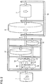
- FIG. 1 components are identified schematically as the building blocks of the system.
- Block 1 represents a generic source of reciprocating, possibly asymmetric rotary motion which provides the irregular, inconsistent uncontrolled mechanical energy to Input Shaft 2.
- This shaft transfers the incoming clockwise and counter-clockwise motion to the Push-Pull conversion block 3 which converts the incoming clockwise and counter-clockwise motion into a unidirectional rotary motion.
- Revolution Multiplier 4 adjusts the number of revolutions of the Input Shaft 2 with the engine speed desired on Output Shaft 5.
- Flywheel 6, integrated with the Output Shaft 5 has sufficient dimensions and mass to mitigate the asymmetry of parameters such as speed and torque of the clockwise and counterclockwise motions applied to the Input Shaft 2.
- Generic User device 7 may be connected to Output Shaft 5 to exploit the unidirectional and continuous rotary motion.
- Block 1 representing source of reciprocating, irregular, inconsistent uncontrolled mechanical energy is integrated with the input shaft 2 that moves in the clockwise and counterclockwise by the mechanical energy source.
- Attached to input shaft 2 are two internal freewheel gears with pawls 8, 9 which are paired with two external and concentric gears 10, 11.
- the internal and external gear arrangement along with their pawls are commonly referred to as freewheel or ratchet. Their purpose is to engage and transfer power only in one direction of rotation while the other rotates freely when not engaged.
- the pairs 8, 10 and 9, 11 engage and transfer the power alternately depending on whether the input shaft 2 turns clockwise or counterclockwise.
- the input shaft 2 When the input shaft 2 rotates in a clockwise direction, it activates the freewheel formed by the pair of internal and external freewheel gears 8 and 10 and the power is transferred to the lower transition gear 12 on lower transition shaft 13 which rotates counterclockwise with lower large-diameter transition gear 14 and transfers power to the output shaft 5, rotating it clockwise.
- the size of the lower large-diameter transition gear 14 and the size and mass of the flywheel 6 are determined by the amount of speed and torque required by the user device 7.
- Converter enclosure 3 is filled with machine oil and fitted with bearings for all shafts that come in contact with braces to reduce friction and wear and increase operational efficiency and lifespan. It is to be noted that the converter enclosure 3 shown in Fig. 2 may accommodate the push-pull conversion block 3 and the revolution multiplier 4 as explained referring to Fig. 1 .
- Frame 18 provides a sturdy structure to which flywheel 6 and the user device 7 are mounted. Bearings are provided on the frame 18 to support the output shaft 5.
- the present disclosure may be realized by technically equivalent configuration using devices or materials suitable for the purpose and scope that conform to the size of the constituent parts and can vary in a manner appropriate but consistent with the proposed solution.
- the proposed solution is applicable to systems of power conversion from a source of alternating motion, where appropriate; asymmetric and variable intensity, to a continuous rotary motion and homogeneous regardless of scale factors and the range of powers involved.
- Fig.2 The configuration shown in Fig.2 is just one example of how the present disclosure may be configured.
- Other variations in components and configurations included within the scope of the present disclosure include, but are not limited to, support structure, such as supporting walls, bearings, source of input power, such as rods, shafts and gears, geometry of the components, and directions of rotation consistent with the principle of operation.
- Transmission components such as gears, belts, chains, toothed bars, ropes, and other technical equivalents that drive input shaft 2 may be used along with other components such as pistons, floats, and similar plungers with alternating motion can be converted into a continuous motion.
- output shaft 5 can be linked to a variety of user equipment such as generators, compressors, turbines, and other devices requiring continuous axial rotational mechanical energy.
Landscapes
- Engineering & Computer Science (AREA)
- General Engineering & Computer Science (AREA)
- Mechanical Engineering (AREA)
- Transmission Devices (AREA)
Applications Claiming Priority (1)
| Application Number | Priority Date | Filing Date | Title |
|---|---|---|---|
| PCT/JP2017/017000 WO2018198334A1 (ja) | 2017-04-28 | 2017-04-28 | 機械的変換器 |
Publications (2)
| Publication Number | Publication Date |
|---|---|
| EP3617552A1 true EP3617552A1 (de) | 2020-03-04 |
| EP3617552A4 EP3617552A4 (de) | 2021-01-13 |
Family
ID=63918110
Family Applications (1)
| Application Number | Title | Priority Date | Filing Date |
|---|---|---|---|
| EP17907420.8A Ceased EP3617552A4 (de) | 2017-04-28 | 2017-04-28 | Mechanischer wandler |
Country Status (6)
| Country | Link |
|---|---|
| US (1) | US20200200246A1 (de) |
| EP (1) | EP3617552A4 (de) |
| CN (1) | CN110799774A (de) |
| AU (2) | AU2017411132A1 (de) |
| MX (1) | MX2019012716A (de) |
| WO (1) | WO2018198334A1 (de) |
Families Citing this family (2)
| Publication number | Priority date | Publication date | Assignee | Title |
|---|---|---|---|---|
| US10753443B2 (en) * | 2018-07-15 | 2020-08-25 | Jen-Che Hung | Gear device for clutch |
| CN116247872B (zh) * | 2023-03-23 | 2024-05-14 | 钛玛科(北京)工业科技有限公司 | 一种单电机控制双轴的机构及方法 |
Family Cites Families (7)
| Publication number | Priority date | Publication date | Assignee | Title |
|---|---|---|---|---|
| JPH0663551B2 (ja) * | 1985-10-29 | 1994-08-22 | コニカ株式会社 | 自動原稿搬送装置の駆動装置 |
| JP2949177B2 (ja) * | 1987-04-10 | 1999-09-13 | 芝浦メカトロニクス株式会社 | 駆動装置 |
| JPH074954U (ja) * | 1993-06-24 | 1995-01-24 | 武夫 小路 | 変則な回転による回転機 |
| TWI231345B (en) * | 2001-08-03 | 2005-04-21 | Sunyen Co Ltd | Driving device automatically applying variable torque to output shaft rotating with constant speed |
| JP2004050414A (ja) * | 2002-07-16 | 2004-02-19 | Japan Steel Works Ltd:The | 射出成形機の可塑化装置 |
| JP2005138784A (ja) * | 2003-11-10 | 2005-06-02 | Toyota Motor Corp | 動力伝達システム |
| JP5786187B1 (ja) * | 2014-07-14 | 2015-09-30 | 浩平 速水 | 発電システム |
-
2017
- 2017-04-28 CN CN201780092568.2A patent/CN110799774A/zh active Pending
- 2017-04-28 AU AU2017411132A patent/AU2017411132A1/en not_active Abandoned
- 2017-04-28 US US16/608,330 patent/US20200200246A1/en not_active Abandoned
- 2017-04-28 MX MX2019012716A patent/MX2019012716A/es unknown
- 2017-04-28 WO PCT/JP2017/017000 patent/WO2018198334A1/ja not_active Ceased
- 2017-04-28 EP EP17907420.8A patent/EP3617552A4/de not_active Ceased
-
2021
- 2021-09-02 AU AU2021225199A patent/AU2021225199A1/en not_active Abandoned
Also Published As
| Publication number | Publication date |
|---|---|
| US20200200246A1 (en) | 2020-06-25 |
| CN110799774A (zh) | 2020-02-14 |
| WO2018198334A1 (ja) | 2018-11-01 |
| EP3617552A4 (de) | 2021-01-13 |
| MX2019012716A (es) | 2020-08-13 |
| AU2017411132A1 (en) | 2019-12-19 |
| AU2021225199A1 (en) | 2021-09-30 |
Similar Documents
| Publication | Publication Date | Title |
|---|---|---|
| US8641570B2 (en) | Infinitely variable motion control (IVMC) for generators, transmissions and pumps/compressors | |
| US7862292B2 (en) | Horizontal motion wave power generator | |
| US8986158B2 (en) | Reduction gearing with a high reduction ratio | |
| GB2463102A (en) | Permanent magnet couplings | |
| CN105228942B (zh) | 动力传递装置 | |
| AU2021225199A1 (en) | Mechanical converter | |
| EP3165794B1 (de) | Vorrichtung, übertragung und universelle mechanische kupplung von kräften mit verschiedenen grössen und richtungen | |
| CA2677552C (en) | Continuously variable transmission | |
| RU2654367C2 (ru) | Турбинная энергетическая установка | |
| US4089228A (en) | Motion generating mechanism | |
| US3960036A (en) | Torque converter | |
| US20170234405A1 (en) | Mechanical converter | |
| CN104373515A (zh) | 多轴波动转动传递装置及其应用的发电装置 | |
| CN203822957U (zh) | 旋转动力省力传递装置 | |
| EP2112403B1 (de) | Mechanischer Drehmomentwandler | |
| US20150211611A1 (en) | Crank-less motion converter | |
| CN104019188A (zh) | 旋转动力省力传递装置 | |
| JP2016145638A (ja) | 遊星歯車装置 | |
| SE1050347A1 (sv) | Kraftöverföringsanordning och metod för överföring av vridmoment | |
| WO2013168046A1 (en) | Dual planetary system | |
| JP2015038361A (ja) | 動力倍増機 | |
| JP2012007720A (ja) | 回転伝達安定装置 | |
| JP2005226793A (ja) | 変速装置 | |
| KR20120008639A (ko) | 무단변속장치 |
Legal Events
| Date | Code | Title | Description |
|---|---|---|---|
| STAA | Information on the status of an ep patent application or granted ep patent |
Free format text: STATUS: THE INTERNATIONAL PUBLICATION HAS BEEN MADE |
|
| PUAI | Public reference made under article 153(3) epc to a published international application that has entered the european phase |
Free format text: ORIGINAL CODE: 0009012 |
|
| STAA | Information on the status of an ep patent application or granted ep patent |
Free format text: STATUS: REQUEST FOR EXAMINATION WAS MADE |
|
| 17P | Request for examination filed |
Effective date: 20191128 |
|
| AK | Designated contracting states |
Kind code of ref document: A1 Designated state(s): AL AT BE BG CH CY CZ DE DK EE ES FI FR GB GR HR HU IE IS IT LI LT LU LV MC MK MT NL NO PL PT RO RS SE SI SK SM TR |
|
| AX | Request for extension of the european patent |
Extension state: BA ME |
|
| DAV | Request for validation of the european patent (deleted) | ||
| DAX | Request for extension of the european patent (deleted) | ||
| REG | Reference to a national code |
Ref country code: DE Ref legal event code: R079 Free format text: PREVIOUS MAIN CLASS: F16H0031000000 Ipc: F16H0003000000 |
|
| A4 | Supplementary search report drawn up and despatched |
Effective date: 20201216 |
|
| RIC1 | Information provided on ipc code assigned before grant |
Ipc: F16H 3/00 20060101AFI20201210BHEP |
|
| STAA | Information on the status of an ep patent application or granted ep patent |
Free format text: STATUS: EXAMINATION IS IN PROGRESS |
|
| 17Q | First examination report despatched |
Effective date: 20211223 |
|
| REG | Reference to a national code |
Ref country code: DE Ref legal event code: R003 |
|
| STAA | Information on the status of an ep patent application or granted ep patent |
Free format text: STATUS: THE APPLICATION HAS BEEN REFUSED |
|
| 18R | Application refused |
Effective date: 20230925 |