EP3617558B1 - Dispositif de levier de vitesses - Google Patents
Dispositif de levier de vitesses Download PDFInfo
- Publication number
- EP3617558B1 EP3617558B1 EP19193954.5A EP19193954A EP3617558B1 EP 3617558 B1 EP3617558 B1 EP 3617558B1 EP 19193954 A EP19193954 A EP 19193954A EP 3617558 B1 EP3617558 B1 EP 3617558B1
- Authority
- EP
- European Patent Office
- Prior art keywords
- gearshift lever
- gearshift
- moved
- lever
- lock
- Prior art date
- Legal status (The legal status is an assumption and is not a legal conclusion. Google has not performed a legal analysis and makes no representation as to the accuracy of the status listed.)
- Active
Links
Images


Classifications
-
- B—PERFORMING OPERATIONS; TRANSPORTING
- B60—VEHICLES IN GENERAL
- B60K—ARRANGEMENT OR MOUNTING OF PROPULSION UNITS OR OF TRANSMISSIONS IN VEHICLES; ARRANGEMENT OR MOUNTING OF PLURAL DIVERSE PRIME-MOVERS IN VEHICLES; AUXILIARY DRIVES FOR VEHICLES; INSTRUMENTATION OR DASHBOARDS FOR VEHICLES; ARRANGEMENTS IN CONNECTION WITH COOLING, AIR INTAKE, GAS EXHAUST OR FUEL SUPPLY OF PROPULSION UNITS IN VEHICLES
- B60K20/00—Arrangement or mounting of change-speed gearing control devices in vehicles
- B60K20/02—Arrangement or mounting of change-speed gearing control devices in vehicles of initiating means
-
- F—MECHANICAL ENGINEERING; LIGHTING; HEATING; WEAPONS; BLASTING
- F16—ENGINEERING ELEMENTS AND UNITS; GENERAL MEASURES FOR PRODUCING AND MAINTAINING EFFECTIVE FUNCTIONING OF MACHINES OR INSTALLATIONS; THERMAL INSULATION IN GENERAL
- F16H—GEARING
- F16H59/00—Control inputs to control units of change-speed- or reversing-gearings for conveying rotary motion
- F16H59/02—Selector apparatus
- F16H59/0204—Selector apparatus for automatic transmissions with means for range selection and manual shifting, e.g. range selector with tiptronic
-
- F—MECHANICAL ENGINEERING; LIGHTING; HEATING; WEAPONS; BLASTING
- F16—ENGINEERING ELEMENTS AND UNITS; GENERAL MEASURES FOR PRODUCING AND MAINTAINING EFFECTIVE FUNCTIONING OF MACHINES OR INSTALLATIONS; THERMAL INSULATION IN GENERAL
- F16H—GEARING
- F16H59/00—Control inputs to control units of change-speed- or reversing-gearings for conveying rotary motion
- F16H59/02—Selector apparatus
- F16H59/0278—Constructional features of the selector lever, e.g. grip parts, mounting or manufacturing
-
- F—MECHANICAL ENGINEERING; LIGHTING; HEATING; WEAPONS; BLASTING
- F16—ENGINEERING ELEMENTS AND UNITS; GENERAL MEASURES FOR PRODUCING AND MAINTAINING EFFECTIVE FUNCTIONING OF MACHINES OR INSTALLATIONS; THERMAL INSULATION IN GENERAL
- F16H—GEARING
- F16H59/00—Control inputs to control units of change-speed- or reversing-gearings for conveying rotary motion
- F16H59/02—Selector apparatus
- F16H59/04—Ratio selector apparatus
-
- F—MECHANICAL ENGINEERING; LIGHTING; HEATING; WEAPONS; BLASTING
- F16—ENGINEERING ELEMENTS AND UNITS; GENERAL MEASURES FOR PRODUCING AND MAINTAINING EFFECTIVE FUNCTIONING OF MACHINES OR INSTALLATIONS; THERMAL INSULATION IN GENERAL
- F16H—GEARING
- F16H59/00—Control inputs to control units of change-speed- or reversing-gearings for conveying rotary motion
- F16H59/02—Selector apparatus
- F16H59/08—Range selector apparatus
- F16H59/10—Range selector apparatus comprising levers
-
- F—MECHANICAL ENGINEERING; LIGHTING; HEATING; WEAPONS; BLASTING
- F16—ENGINEERING ELEMENTS AND UNITS; GENERAL MEASURES FOR PRODUCING AND MAINTAINING EFFECTIVE FUNCTIONING OF MACHINES OR INSTALLATIONS; THERMAL INSULATION IN GENERAL
- F16H—GEARING
- F16H59/00—Control inputs to control units of change-speed- or reversing-gearings for conveying rotary motion
- F16H59/02—Selector apparatus
- F16H2059/026—Details or special features of the selector casing or lever support
Definitions
- the present invention relates to a gearshift lever device of an automatic transmission.
- the gearshift lever device of Japanese Patent Application Publication No. H9-263151 uses a joint to allow a gearshift lever to be moved in a front-rear direction (shift direction) in the auto mode and the manual mode and to be moved in a right-left direction (select direction) for switching between the auto mode and the manual mode.
- the joint includes a first tube body along the right-left direction (select direction) and a second tube body along the front-rear direction (shift direction).
- the gearshift lever is moved in the front-rear direction (shift direction) about an axial center of the first tube body and is moved in the right-left direction (select direction) about an axial center of the second tube body.
- a compression rod inserted in the tubular gearshift lever is pushed upward by a spring.
- the spring is supported with its lower end engaged with a protrusion portion formed on an upper surface of the second tube body. With an operation button formed at an upper portion of the gearshift lever pressed, the compression rod is moved downward against the spring to enable operations of the gearshift lever in the auto mode.
- a gearshift lever device according to the preamble of independent claim 1 is disclosed in Japanese Patent Application Publication No. 2005-119440 .
- the object of the present invention is to implement a configuration for moving a gearshift lever in a right-left direction and a front-rear direction by moving the gearshift lever about a spherical portion on a lower portion of the gearshift lever, which is also capable of supporting a lower end of an elastic body pushing a compression rod upward
- a gearshift lever device according to the present invention is defined in independent claim 1. Preferred embodiments are set out in the dependent claims.
- a gearshift lever device allows a gearshift lever to be operated in both an auto mode and a manual mode.
- the gearshift lever device includes a gearshift lever, a spherical portion that is formed in a lower portion of the gearshift lever and supports the gearshift lever while allowing the gearshift lever to be moved in a front-rear direction in the auto mode or the manual mode and supports the gearshift lever while allowing the gearshift lever to be moved in a right-left direction to switch between the auto mode or the manual mode; a compression rod that is arranged in the gearshift lever movably in a vehicle top-down direction and that, when an operation portion formed on the gearshift lever is operated in the auto mode, is moved downward in the gearshift lever to enable operations of the gearshift lever in the front-rear direction; an elastic body that is arranged at a lower portion in the gearshift lever and pushes the compression rod upward; and a support member that is attached to the gearshift lever and supports a lower portion of the elastic body.
- the support member includes an
- a gearshift lever device of an aspect of the present invention it is possible to implement a configuration for moving a gearshift lever about a spherical portion on a lower portion of the gearshift lever to move the gearshift lever in a right-left direction and a front-rear direction, which still can support a lower end of an elastic body pushing a compression rod.
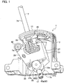
- Fig. 1 illustrates an internal configuration of a gearshift lever device 1 used in a vehicle (an automobile).
- "front-rear direction” and “right-left direction” respectively correspond to a front-rear direction and a right-left direction of the vehicle in which the gearshift lever device 1 is mounted.
- an arrow X indicates the right-left direction (select direction)
- an arrow Y indicates the front-rear direction (shift direction)
- an arrow Z indicates a top-down direction (vehicle top-down direction).
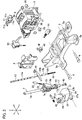
- a housing 3 is assembled on a base 5 illustrated in Fig. 2 with fix pins 6.
- the base 5 is fixed on an unillustrated vehicle body using mounting portions 5a.
- a lower portion of a gearshift lever 7 is inserted to the housing 3.
- a cover 8 is put on one opening in the right-left direction X of the housing 3.
- an upper surface portion 9 of the housing 3 has a curved concave shape, which is an arc shape in the front-rear direction Y.
- a cover panel 11 is put on the upper surface portion 9.
- An auto mode shift path 11a for automatic transmission operation and a manual mode shift path 11b for manual transmission operation are formed on the cover panel 11.
- AD (drive) range of the auto mode shift path 11a and a neutral position of the manual mode shift path 11b are connected through a select operation shift path 11c.
- the auto mode shift path 11a is long in the front-rear direction Y, and the manual mode shift path 11b is positioned around a rear portion of the auto mode shift path 11a and has a shorter length in the front-rear direction Y than the auto mode shift path 11a.
- An opening 9a corresponding to the auto mode shift path 11a, the manual mode shift path 11b, and the select operation shift path 11c is formed in the upper surface portion 9 of the housing 3.
- the gearshift lever 7 includes a lever main body 7A, which is a cylinder and is hollow along the entire length in an axial direction, and a resin molded body 7B, which is molded of resin integrally on a lower outer circumference of the lever main body 7A.
- a compression rod 13 is inserted in the lever main body 7A movably in the axial direction.
- a cylindrical portion 17 is formed on a lower end portion, and a spherical portion 19 is formed next to an upper portion of the cylindrical portion 17.
- a tube portion 21 is obliquely formed on a side portion above the spherical portion 19.
- a check spring 23 and a check pin 25 that is pushed in an upward projecting direction by the check spring 23 are housed in the tube portion 21.
- the check pin 25 is engaged with an unillustrated check groove formed in the housing 3.
- the resin molded body 7B is supported by a select block 27.
- the select block 27 includes a front wall portion 29, a rear wall portion 31, and a bottom wall portion 33.
- a spherical reception portion 35 that receives the spherical portion 19 is formed on the bottom wall portion 33.
- a cylindrical portion 17 is inserted to penetrate through a through hole 35a formed in the spherical reception portion 35.
- the through hole 35a is formed to be greater than an outer diameter of the cylindrical portion 17 so as to allow the cylindrical portion 17 to move in the right-left direction when the gearshift lever 7 is moved in the select operation shift path 11c in the right-left direction.
- a lower end of the lever main body 7A reaches a center position of the spherical portion 19.
- a cylindrical space in the cylindrical portion 17 of the resin molded body 7B is continuously formed in the spherical portion 19, and the space is continued to the internal space of the lever main body 7A.
- Shaft portions 37a, 37b extending in the right-left direction X are formed in right and left sides of the spherical reception portion 35.
- the shaft portions 37a, 37b are rotatably supported by a shaft hole 39 of the housing 3 with bushes 36. This allows the select block 27 to be shifted in the front-rear direction Y about the shaft portions 37a, 37b.
- the gearshift lever 7 is moved in the right-left direction (select direction) X about the spherical portion 19.
- the gearshift lever 7 is moved from the auto mode shift path 11a in the left direction to the manual mode shift path 11b, the fitting of the resin molded body 7B and the select block 27 is released.
- the gearshift lever 7 is moved from the manual mode shift path 11b in the right direction to the auto mode shift path 11a, the resin molded body 7B is fitted to the select block 27.
- the fitting of the resin molded body 7B and the select block 27 is made by inserting an upper portion of the resin molded body 7B to a space between the front wall portion 29 and the rear wall portion 31 of the select block 27.
- the compression rod 13 is divided into a rod upper portion 13a and a rod lower portion 13b that is shorter than the rod upper portion 13a, and a position pin 45 extending in the right-left direction X is arranged between the rod upper portion 13a and the rod lower portion 13b.
- the position pin 45 includes insertion protrusions 45a, 45b formed on the top and the bottom of its middle part in the right-left direction, and the insertion protrusions 45a, 45b are respectively inserted to insides of the rod upper portion 13a and the rod lower portion 13b.
- a through hole 7a that is long in the top-down direction Z is formed in a part corresponding to the resin molded body 7B of the gearshift lever 7.
- the through hole 7a penetrates the lever main body 7A and the resin molded body 7B at a position above the spherical portion 19.
- the position pin 45 is inserted to the through hole 7a movably in the top-down direction Z.
- the position pin 45 projects outside the resin molded body 7B from the through hole 7a, and the projecting parts around tip ends are inserted to a position gate 47 of the housing 3.
- the position pin 45 is moved inside the position gate 47 by operation of the gearshift lever 7.
- a coil spring 41 as an elastic body is housed below the rod lower portion 13b of the compression rod 13.
- the coil spring 41 pushes the compression rod 13 upward.
- a protrusion 13b1 projecting downward from a lower end of the rod lower portion 13b is inserted to an upper portion of the coil spring 41.
- a stopper 43 as a support member attached on a lower end of the gearshift lever 7 prevents the coil spring 41 from falling out.
- the stopper 43 includes a substantially ring shaped base portion 43a.
- the base portion 43a includes a pair of arc portions 43a1 opposed to each other and a pair of rectangular portions 43a2 opposed to each other in positions spaced 90 degrees apart in a circumferential direction from the positions of the arc portions 43a1.
- a pair of leg portions 43b are formed to stand upright from inner circumferential sides of the corresponding arc portions 43a1.
- an upper end surface of the base portion 43a is in contact with a lower end of the cylindrical portion 17 of the resin molded body 7B.
- a total outer diameter of the pair of arc portions 43a1 is substantially equal to an outer diameter of the cylindrical portion 17, a substantially entire area of top surfaces of the arc portions 43a1 is in contact with a lower end surface of the cylindrical portion 17.
- the pair of leg portions 43b are positioned to oppose to each other.
- Each leg portion 43b forms a part (substantially 1/4) of a cylindrical member in a circumferential direction. Consequently, openings 43c are respectively formed between each of the pair of leg portions 43b in the circumferential direction.
- a flat plate portion 43d As illustrated in Fig. 5C , the flat plate portion 43d is substantially oval in plan view. A protrusion portion 43e projecting upward is formed on a top surface of the flat plate portion 43d. A cross section of the protrusion portion 43e is circle, and a diameter of the circle of the protrusion portion 43e in a tip end side (upper end side) is smaller than that in a base end side (lower end side).
- Each lock portion 43f includes an arm portion 43fl including an upper portion connected to the flat plate portion 43d and a tab portion 43f2 formed on a lower portion of the arm portions 43fl.
- the arm portion 43f1 is long in the top-down direction Z and is elastically deformed such that the tab portion 43f2 on the lower portion is moved between inside and outside of the opening 43c while being supported at the upper portion.
- the tab portions 43f2 are positioned above the base portion 43a and are away from the base portion 43a.
- Lock holes 17a into which the tab portions 43f2 enter are formed in the cylindrical portion 17 of the resin molded body 7B.
- the tab portions 43f2 enter the lock holes 17a, and the tab portions 43f2 prevent the stopper 43 from falling out from the cylindrical portion 17.
- outer circumferential surfaces of the leg portions 43b are substantially in contact with an inner circumferential surface of the cylindrical portion 17.
- tip ends of the tab portions 43f2 press the inner circumferential surface of the cylindrical portion 17, and thus the pair of arm portions 43f1 are elastically deformed in a direction in which they come close to each other. Thereafter, once the tab portions 43f2 are locked in the lock holes 17a, the pair of arm portions 43f1 is restored from the elastically deformed state to the original form.
- the stopper 43 While the stopper 43 is attached on the cylindrical portion 17, the protrusion portion 43e is inserted in the coil spring 41 as illustrated in Fig. 3 . In this state, a lower end of the coil spring 41 is in contact with the top surface of the flat plate portion 43d. In other words, the flat plate portion 43d serves as a spring receiver of the coil spring 41.
- each tab portion 43f2 includes an upper inclined surface 43f3, an outer circumferential cylindrical surface 43f4, and a lower end surface 43f5.
- the upper inclined surface 43f3 is inclined such that a lower end is positioned farther to the outside from a central axis in the top-down direction Z than an upper end.
- an upper end is continued to the upper inclined surface 43f3, and a lower end is continued to the lower end surface 43f5.
- the lower end surface 43f5 is inclined such that an outer circumference side end portion is located below an inner circumference side end portion. Since the lower end surface 43f5 is inclined, tip end sides of the tab portions 43f2 are elastically deformed upward easily when the stopper 43 is pushed downward by the coil spring 41 and the tab portions 43f2 are pressed on edges of the lock holes 17a.
- Fig. 2 illustrates constituents such as a shift-lock lever 49, a solenoid 51 that releases the shift-lock lever 49, and a forcible release lever 53 that releases shift-lock by forcibly turning the shift-lock lever 49.
- the shift-lock lever 49 is for preventing the gearshift lever 7 from moving from a parking position when parking the vehicle.
- the solenoid 51 is activated when a brake pedal is stepped down at the start-up of an engine and the gearshift lever 7 is in a P (parking) range of the auto mode shift path 11a, and then the shift-lock of the shift-lock lever 49 is released.
- the operation button on the upper portion of the gearshift lever 7 is pressed in this state, the compression rod 13 is moved downward with the position pin 45. This allows the position pin 45 to move rearward in the position gate 47 and allows the gearshift lever 7 to be moved in the front-rear direction in the auto mode shift path 11a. While the compression rod 13 is moving downward, the coil spring 41 is compressed. Once stopping the operation of pressing the operation button, the compression rod 13 is pushed by the coil spring 41 and moved upward.
- the gearshift lever device 1 of this embodiment allows the gearshift lever 7 to be operated in both the auto mode and manual mode.
- the gearshift lever device 1 includes the spherical portion 19 that is formed in the lower portion of the gearshift lever 7 and supports the gearshift lever 7 while allowing the gearshift lever 7 to be moved in the front-rear direction Y in the auto mode or the manual mode and supports the gearshift lever 7 while allowing the gearshift lever 7 to be moved in the right-left direction X to switch between the auto mode or the manual mode.
- the gearshift lever device 1 includes the compression rod 13 that is arranged in the gearshift lever 7 movably in the axial direction and that, when the operation button as the operation portion formed on the gearshift lever 7 is operated in the auto mode, is moved downward in the gearshift lever 7 to enable operations of the gearshift lever 7 in the front-rear direction Y.
- the gearshift lever device 1 includes the coil spring 41 that is arranged at the lower portion in the gearshift lever 7 and pushes the compression rod 13 upward and the stopper 43 that is attached to the gearshift lever 7 and supports the lower portion of the coil spring 41.
- the stopper 43 includes insertion portions (leg portions 43b, protrusion portions 43e) that are inserted from the opening at the lower end of the gearshift lever 7 and the lock portions 43f that are locked in the lock holes 17a in the gearshift lever 7 with the insertion portions inserted in the gearshift lever 7.
- the configuration for moving the gearshift lever 7 in the right-left direction (select direction) X and the front-rear direction (shift direction) Y is implemented by moving the gearshift lever 7 about the spherical portion 19 formed in the lower portion of the gearshift lever 7.
- the stopper 43 Even in such a gearshift lever device 1, the lower end of the coil spring 41 pushing the compression rod 13 upward can be supported by the stopper 43.
- the insertion portions, or specifically the leg portions 43b are inserted in the gearshift lever 7, and the outer circumferential surfaces of the leg portions 43b are substantially in contact with the inner circumferential surface of the gearshift lever 7 (cylindrical portion 17); thus, the parts are assembled in a stable manner.
- the elastic body pushing the compression rod 13 upward is formed of the coil spring 41, and the protrusion portion 43e on the tip end side of the lock portion 43f is inserted in the coil spring 41.
- the protrusion portion 43e can suppress the deformation of the coil spring 41 curved in a direction crossing the compression or extension direction.
- the lock portions 43f of this embodiment include the tab portions 43f2, a trailing end side of the tab portion in the insertion direction of the insertion portions being pressed on the edges of the lock holes 17a while the tab portions 43f2 are locked in the lock holes 17a.
- the lower end surface 43f5 of each tab portion 43f2, which is a portion opposed to the edge, is inclined such that the tip end side of the tab portion 43f2 is positioned behind the base end side of the tab portion 43f2 in the right-left direction of the vehicle (X).
- the tip end sides of the tab portions 43f2 are easily elastically deformed upward when the stopper 43 is pushed downward by the coil spring 41 and the lower end surfaces 43f5 are pressed on the edges of the lock holes 17a.
- the upward elastic deformation of the tab portions 43f2 makes it possible to suppress a backlash generated when the stopper 43 is attached on the cylindrical portion 17, and thus the parts can be assembled in the stable manner.
- the coil spring 41 is used as the elastic body that pushes the compression rod 13 upward.
- the compression rod 13 can be moved downward by a predetermined amount when the operation button is pressed, it is not limited to the coil spring 41.
- the protrusion portions 43e are not necessarily required as long as the configuration allows the lower end of the coil spring 41 to be in contact with the flat plate portion 43d.
Landscapes
- Engineering & Computer Science (AREA)
- General Engineering & Computer Science (AREA)
- Mechanical Engineering (AREA)
- Chemical & Material Sciences (AREA)
- Combustion & Propulsion (AREA)
- Transportation (AREA)
- Arrangement Or Mounting Of Control Devices For Change-Speed Gearing (AREA)
Claims (3)
- Dispositif de levier de changement de vitesse (1) qui permet l'actionnement d'un levier de changement de vitesse (7) en mode automatique et en mode manuel, comprenant :le levier de changement de vitesse (7) ;une portion sphérique (19) qui est formée dans une portion inférieure du levier de changement de vitesse (7) et prend en charge le levier de changement de vitesse (7) tout en permettant au levier de changement de vitesse (7) d'être déplacé en direction avant-arrière en mode automatique ou en mode manuel et prend en charge le levier de changement de vitesse (7) tout en permettant au levier de changement de vitesse (7) d'être déplacé en direction gauche-droite pour commuter entre le mode automatique et le mode manuel ;une tige de compression (13) qui est agencée dans le levier de changement de vitesse (7) de façon mobile en direction haut-bas d'un véhicule, et qui, quand une portion d'actionnement formée sur le levier de changement de vitesse (7) est actionnée en mode automatique, est déplacée vers le bas dans le levier de changement de vitesse (7) pour permettre des actionnements du levier de changement de vitesse (7) en direction avant-arrière ;un corps élastique qui est agencé sur une portion inférieure dans le levier de changement de vitesse (7) et pousse la tige de compression (13) vers le haut ; etun élément de support (43) qui est attaché au levier de changement de vitesse (7) et supporte une portion inférieure du corps élastique, dans lequell'élément de support (43) comprend une portion d'insertion (43b, 43e) qui est insérée par une ouverture à une extrémité inférieure du levier de changement de vitesse (7),caractériséen ce que l'élément de support (43) comprend en outre une portion de verrouillage (43f) qui est verrouillée dans un trou de verrouillage (17a) dans le levier de changement de vitesse (7) avec la portion d'insertion (43b, 43e) insérée dans le levier de changement de vitesse (7).
- Dispositif de levier de changement de vitesse (1) selon la revendication 1, dans lequel
le corps élastique est constitué d'un ressort hélicoïdal (41), et la portion d'insertion située au-dessus de la portion de verrouillage (43f) est insérée dans le ressort hélicoïdal (41). - Dispositif de levier de changement de vitesse (1) selon la revendication 2, dans lequel
la portion de verrouillage (43f) comprend une portion d'ergot (43f2), un côté extrémité arrière de la portion d'ergot (43f2) en direction d'insertion des portions d'insertion étant poussé sur un bord du trou de verrouillage (17a) alors que la portion d'ergot (43f2) est verrouillée dans le trou de verrouillage (17a),
la surface d'extrémité inférieure (43f5) de la portion d'ergot (43f2), qui est une portion opposée au bord du trou de verrouillage (17a), est inclinée de telle sorte qu'un côté extrémité de pointe de la portion d'ergot (43f2) est positionné derrière un côté extrémité de base de la portion d'ergot (43f2) en direction gauche-droite du véhicule (X).
Applications Claiming Priority (1)
| Application Number | Priority Date | Filing Date | Title |
|---|---|---|---|
| JP2018162600A JP2020032926A (ja) | 2018-08-31 | 2018-08-31 | シフトレバー装置 |
Publications (2)
| Publication Number | Publication Date |
|---|---|
| EP3617558A1 EP3617558A1 (fr) | 2020-03-04 |
| EP3617558B1 true EP3617558B1 (fr) | 2021-05-12 |
Family
ID=67777115
Family Applications (1)
| Application Number | Title | Priority Date | Filing Date |
|---|---|---|---|
| EP19193954.5A Active EP3617558B1 (fr) | 2018-08-31 | 2019-08-28 | Dispositif de levier de vitesses |
Country Status (4)
| Country | Link |
|---|---|
| US (1) | US20200072342A1 (fr) |
| EP (1) | EP3617558B1 (fr) |
| JP (1) | JP2020032926A (fr) |
| CN (1) | CN110871681A (fr) |
Families Citing this family (1)
| Publication number | Priority date | Publication date | Assignee | Title |
|---|---|---|---|---|
| KR20210044341A (ko) * | 2019-10-14 | 2021-04-23 | 현대자동차주식회사 | 차량용 변속레버 조립체 |
Family Cites Families (10)
| Publication number | Priority date | Publication date | Assignee | Title |
|---|---|---|---|---|
| JP3352318B2 (ja) | 1996-03-27 | 2002-12-03 | 富士機工株式会社 | 自動車の自動変速機のシフト装置 |
| DE19844278C1 (de) * | 1998-09-26 | 2000-01-05 | Porsche Ag | Widerlager für eine Feder |
| JP4388342B2 (ja) * | 2003-10-16 | 2009-12-24 | 本田技研工業株式会社 | 自動変速機のシフトレバー装置 |
| JP5086130B2 (ja) * | 2008-02-28 | 2012-11-28 | デルタ工業株式会社 | 自動車用変速機のシフト装置 |
| JP5225937B2 (ja) * | 2009-06-08 | 2013-07-03 | デルタ工業株式会社 | 自動変速機のシフト装置 |
| CN203189700U (zh) * | 2013-03-26 | 2013-09-11 | 安徽江淮汽车股份有限公司 | 一种换挡杆组件及自动变速器换挡操纵机构 |
| JP2015006866A (ja) * | 2013-06-26 | 2015-01-15 | デルタ工業株式会社 | 自動変速機のシフト装置 |
| JP6144722B2 (ja) * | 2015-06-01 | 2017-06-07 | トヨタ自動車株式会社 | 車両用シフト装置 |
| JP2017081332A (ja) * | 2015-10-27 | 2017-05-18 | 富士機工株式会社 | シフトレバー装置 |
| CN205780804U (zh) * | 2016-05-23 | 2016-12-07 | 宁波贝尔达汽车控制系统有限公司 | 抑制卡顿效果好的自动变速箱操纵机构 |
-
2018
- 2018-08-31 JP JP2018162600A patent/JP2020032926A/ja active Pending
-
2019
- 2019-08-21 US US16/546,383 patent/US20200072342A1/en not_active Abandoned
- 2019-08-28 EP EP19193954.5A patent/EP3617558B1/fr active Active
- 2019-08-30 CN CN201910817413.1A patent/CN110871681A/zh not_active Withdrawn
Non-Patent Citations (1)
| Title |
|---|
| None * |
Also Published As
| Publication number | Publication date |
|---|---|
| US20200072342A1 (en) | 2020-03-05 |
| CN110871681A (zh) | 2020-03-10 |
| JP2020032926A (ja) | 2020-03-05 |
| EP3617558A1 (fr) | 2020-03-04 |
Similar Documents
| Publication | Publication Date | Title |
|---|---|---|
| US6230579B1 (en) | Multi-mode shifter assembly joint | |
| US7900534B2 (en) | Shifter for vehicle transmission | |
| US9032829B2 (en) | Button structure of shift knob | |
| US5372051A (en) | Shift lever assembly for power transmission of automotive vehicle | |
| US8375821B2 (en) | Actuating device | |
| EP0978669A2 (fr) | Dispositif de commande à deux modes pour transmission automatique | |
| US6301994B1 (en) | Shift lever apparatus | |
| US20080098844A1 (en) | Shift lever device | |
| EP3617558B1 (fr) | Dispositif de levier de vitesses | |
| EP3306143B1 (fr) | Dispositif de changement de vitesse pour véhicules à moteur | |
| JP2000043601A5 (fr) | ||
| KR100721890B1 (ko) | 시프트 레버 장치 | |
| US20080184837A1 (en) | Shift lever apparatus for automatic transmission | |
| US5575175A (en) | Shift lever assembly | |
| EP3617561A1 (fr) | Dispositif de levier de changement de vitesses | |
| EP2009327A2 (fr) | Appareil de levier de vitesse pour véhicule | |
| EP2009326B1 (fr) | Appareil de levier de vitesse pour véhicule | |
| JPS6234324Y2 (fr) | ||
| US20050217404A1 (en) | Selector apparatus of an automatic transmission of vehicle | |
| CN103522897B (zh) | 车辆用变速杆装置 | |
| JP6653975B2 (ja) | Atシフトレバー装置 | |
| EP3617560B1 (fr) | Dispositif de levier de changement de vitesses | |
| CN117249237A (zh) | 换挡装置 | |
| CN110439995B (zh) | 自动挡换挡器及其限位板、车辆 | |
| KR20250074589A (ko) | 변속 장치 및 상기 변속 장치가 구비된 차량 |
Legal Events
| Date | Code | Title | Description |
|---|---|---|---|
| PUAI | Public reference made under article 153(3) epc to a published international application that has entered the european phase |
Free format text: ORIGINAL CODE: 0009012 |
|
| STAA | Information on the status of an ep patent application or granted ep patent |
Free format text: STATUS: THE APPLICATION HAS BEEN PUBLISHED |
|
| AK | Designated contracting states |
Kind code of ref document: A1 Designated state(s): AL AT BE BG CH CY CZ DE DK EE ES FI FR GB GR HR HU IE IS IT LI LT LU LV MC MK MT NL NO PL PT RO RS SE SI SK SM TR |
|
| AX | Request for extension of the european patent |
Extension state: BA ME |
|
| STAA | Information on the status of an ep patent application or granted ep patent |
Free format text: STATUS: REQUEST FOR EXAMINATION WAS MADE |
|
| 17P | Request for examination filed |
Effective date: 20200902 |
|
| RBV | Designated contracting states (corrected) |
Designated state(s): AL AT BE BG CH CY CZ DE DK EE ES FI FR GB GR HR HU IE IS IT LI LT LU LV MC MK MT NL NO PL PT RO RS SE SI SK SM TR |
|
| REG | Reference to a national code |
Ref country code: DE Ref legal event code: R079 Ref document number: 602019004569 Country of ref document: DE Free format text: PREVIOUS MAIN CLASS: F16H0059020000 Ipc: F16H0059100000 |
|
| GRAP | Despatch of communication of intention to grant a patent |
Free format text: ORIGINAL CODE: EPIDOSNIGR1 |
|
| STAA | Information on the status of an ep patent application or granted ep patent |
Free format text: STATUS: GRANT OF PATENT IS INTENDED |
|
| RIC1 | Information provided on ipc code assigned before grant |
Ipc: F16H 59/02 20060101ALN20201106BHEP Ipc: F16H 59/10 20060101AFI20201106BHEP |
|
| RIC1 | Information provided on ipc code assigned before grant |
Ipc: F16H 59/10 20060101AFI20201119BHEP Ipc: F16H 59/02 20060101ALN20201119BHEP |
|
| INTG | Intention to grant announced |
Effective date: 20201204 |
|
| GRAS | Grant fee paid |
Free format text: ORIGINAL CODE: EPIDOSNIGR3 |
|
| GRAA | (expected) grant |
Free format text: ORIGINAL CODE: 0009210 |
|
| STAA | Information on the status of an ep patent application or granted ep patent |
Free format text: STATUS: THE PATENT HAS BEEN GRANTED |
|
| AK | Designated contracting states |
Kind code of ref document: B1 Designated state(s): AL AT BE BG CH CY CZ DE DK EE ES FI FR GB GR HR HU IE IS IT LI LT LU LV MC MK MT NL NO PL PT RO RS SE SI SK SM TR |
|
| REG | Reference to a national code |
Ref country code: GB Ref legal event code: FG4D |
|
| REG | Reference to a national code |
Ref country code: CH Ref legal event code: EP |
|
| REG | Reference to a national code |
Ref country code: DE Ref legal event code: R096 Ref document number: 602019004569 Country of ref document: DE |
|
| REG | Reference to a national code |
Ref country code: IE Ref legal event code: FG4D |
|
| REG | Reference to a national code |
Ref country code: AT Ref legal event code: REF Ref document number: 1392395 Country of ref document: AT Kind code of ref document: T Effective date: 20210615 |
|
| REG | Reference to a national code |
Ref country code: LT Ref legal event code: MG9D |
|
| REG | Reference to a national code |
Ref country code: AT Ref legal event code: MK05 Ref document number: 1392395 Country of ref document: AT Kind code of ref document: T Effective date: 20210512 |
|
| REG | Reference to a national code |
Ref country code: NL Ref legal event code: MP Effective date: 20210512 |
|
| PG25 | Lapsed in a contracting state [announced via postgrant information from national office to epo] |
Ref country code: AT Free format text: LAPSE BECAUSE OF FAILURE TO SUBMIT A TRANSLATION OF THE DESCRIPTION OR TO PAY THE FEE WITHIN THE PRESCRIBED TIME-LIMIT Effective date: 20210512 Ref country code: BG Free format text: LAPSE BECAUSE OF FAILURE TO SUBMIT A TRANSLATION OF THE DESCRIPTION OR TO PAY THE FEE WITHIN THE PRESCRIBED TIME-LIMIT Effective date: 20210812 Ref country code: FI Free format text: LAPSE BECAUSE OF FAILURE TO SUBMIT A TRANSLATION OF THE DESCRIPTION OR TO PAY THE FEE WITHIN THE PRESCRIBED TIME-LIMIT Effective date: 20210512 Ref country code: HR Free format text: LAPSE BECAUSE OF FAILURE TO SUBMIT A TRANSLATION OF THE DESCRIPTION OR TO PAY THE FEE WITHIN THE PRESCRIBED TIME-LIMIT Effective date: 20210512 Ref country code: LT Free format text: LAPSE BECAUSE OF FAILURE TO SUBMIT A TRANSLATION OF THE DESCRIPTION OR TO PAY THE FEE WITHIN THE PRESCRIBED TIME-LIMIT Effective date: 20210512 |
|
| PGFP | Annual fee paid to national office [announced via postgrant information from national office to epo] |
Ref country code: FR Payment date: 20210820 Year of fee payment: 3 |
|
| PG25 | Lapsed in a contracting state [announced via postgrant information from national office to epo] |
Ref country code: NO Free format text: LAPSE BECAUSE OF FAILURE TO SUBMIT A TRANSLATION OF THE DESCRIPTION OR TO PAY THE FEE WITHIN THE PRESCRIBED TIME-LIMIT Effective date: 20210812 Ref country code: PL Free format text: LAPSE BECAUSE OF FAILURE TO SUBMIT A TRANSLATION OF THE DESCRIPTION OR TO PAY THE FEE WITHIN THE PRESCRIBED TIME-LIMIT Effective date: 20210512 Ref country code: LV Free format text: LAPSE BECAUSE OF FAILURE TO SUBMIT A TRANSLATION OF THE DESCRIPTION OR TO PAY THE FEE WITHIN THE PRESCRIBED TIME-LIMIT Effective date: 20210512 Ref country code: RS Free format text: LAPSE BECAUSE OF FAILURE TO SUBMIT A TRANSLATION OF THE DESCRIPTION OR TO PAY THE FEE WITHIN THE PRESCRIBED TIME-LIMIT Effective date: 20210512 Ref country code: PT Free format text: LAPSE BECAUSE OF FAILURE TO SUBMIT A TRANSLATION OF THE DESCRIPTION OR TO PAY THE FEE WITHIN THE PRESCRIBED TIME-LIMIT Effective date: 20210913 Ref country code: SE Free format text: LAPSE BECAUSE OF FAILURE TO SUBMIT A TRANSLATION OF THE DESCRIPTION OR TO PAY THE FEE WITHIN THE PRESCRIBED TIME-LIMIT Effective date: 20210512 Ref country code: GR Free format text: LAPSE BECAUSE OF FAILURE TO SUBMIT A TRANSLATION OF THE DESCRIPTION OR TO PAY THE FEE WITHIN THE PRESCRIBED TIME-LIMIT Effective date: 20210813 Ref country code: IS Free format text: LAPSE BECAUSE OF FAILURE TO SUBMIT A TRANSLATION OF THE DESCRIPTION OR TO PAY THE FEE WITHIN THE PRESCRIBED TIME-LIMIT Effective date: 20210912 |
|
| PGFP | Annual fee paid to national office [announced via postgrant information from national office to epo] |
Ref country code: DE Payment date: 20210826 Year of fee payment: 3 |
|
| PG25 | Lapsed in a contracting state [announced via postgrant information from national office to epo] |
Ref country code: NL Free format text: LAPSE BECAUSE OF FAILURE TO SUBMIT A TRANSLATION OF THE DESCRIPTION OR TO PAY THE FEE WITHIN THE PRESCRIBED TIME-LIMIT Effective date: 20210512 |
|
| PG25 | Lapsed in a contracting state [announced via postgrant information from national office to epo] |
Ref country code: CZ Free format text: LAPSE BECAUSE OF FAILURE TO SUBMIT A TRANSLATION OF THE DESCRIPTION OR TO PAY THE FEE WITHIN THE PRESCRIBED TIME-LIMIT Effective date: 20210512 Ref country code: DK Free format text: LAPSE BECAUSE OF FAILURE TO SUBMIT A TRANSLATION OF THE DESCRIPTION OR TO PAY THE FEE WITHIN THE PRESCRIBED TIME-LIMIT Effective date: 20210512 Ref country code: RO Free format text: LAPSE BECAUSE OF FAILURE TO SUBMIT A TRANSLATION OF THE DESCRIPTION OR TO PAY THE FEE WITHIN THE PRESCRIBED TIME-LIMIT Effective date: 20210512 Ref country code: SM Free format text: LAPSE BECAUSE OF FAILURE TO SUBMIT A TRANSLATION OF THE DESCRIPTION OR TO PAY THE FEE WITHIN THE PRESCRIBED TIME-LIMIT Effective date: 20210512 Ref country code: SK Free format text: LAPSE BECAUSE OF FAILURE TO SUBMIT A TRANSLATION OF THE DESCRIPTION OR TO PAY THE FEE WITHIN THE PRESCRIBED TIME-LIMIT Effective date: 20210512 Ref country code: ES Free format text: LAPSE BECAUSE OF FAILURE TO SUBMIT A TRANSLATION OF THE DESCRIPTION OR TO PAY THE FEE WITHIN THE PRESCRIBED TIME-LIMIT Effective date: 20210512 Ref country code: EE Free format text: LAPSE BECAUSE OF FAILURE TO SUBMIT A TRANSLATION OF THE DESCRIPTION OR TO PAY THE FEE WITHIN THE PRESCRIBED TIME-LIMIT Effective date: 20210512 |
|
| REG | Reference to a national code |
Ref country code: DE Ref legal event code: R097 Ref document number: 602019004569 Country of ref document: DE |
|
| PLBE | No opposition filed within time limit |
Free format text: ORIGINAL CODE: 0009261 |
|
| STAA | Information on the status of an ep patent application or granted ep patent |
Free format text: STATUS: NO OPPOSITION FILED WITHIN TIME LIMIT |
|
| PG25 | Lapsed in a contracting state [announced via postgrant information from national office to epo] |
Ref country code: MC Free format text: LAPSE BECAUSE OF FAILURE TO SUBMIT A TRANSLATION OF THE DESCRIPTION OR TO PAY THE FEE WITHIN THE PRESCRIBED TIME-LIMIT Effective date: 20210512 |
|
| 26N | No opposition filed |
Effective date: 20220215 |
|
| REG | Reference to a national code |
Ref country code: BE Ref legal event code: MM Effective date: 20210831 |
|
| PG25 | Lapsed in a contracting state [announced via postgrant information from national office to epo] |
Ref country code: IS Free format text: LAPSE BECAUSE OF FAILURE TO SUBMIT A TRANSLATION OF THE DESCRIPTION OR TO PAY THE FEE WITHIN THE PRESCRIBED TIME-LIMIT Effective date: 20210912 Ref country code: LU Free format text: LAPSE BECAUSE OF NON-PAYMENT OF DUE FEES Effective date: 20210828 Ref country code: AL Free format text: LAPSE BECAUSE OF FAILURE TO SUBMIT A TRANSLATION OF THE DESCRIPTION OR TO PAY THE FEE WITHIN THE PRESCRIBED TIME-LIMIT Effective date: 20210512 |
|
| PG25 | Lapsed in a contracting state [announced via postgrant information from national office to epo] |
Ref country code: IT Free format text: LAPSE BECAUSE OF FAILURE TO SUBMIT A TRANSLATION OF THE DESCRIPTION OR TO PAY THE FEE WITHIN THE PRESCRIBED TIME-LIMIT Effective date: 20210512 Ref country code: IE Free format text: LAPSE BECAUSE OF NON-PAYMENT OF DUE FEES Effective date: 20210828 Ref country code: BE Free format text: LAPSE BECAUSE OF NON-PAYMENT OF DUE FEES Effective date: 20210831 |
|
| REG | Reference to a national code |
Ref country code: DE Ref legal event code: R119 Ref document number: 602019004569 Country of ref document: DE |
|
| REG | Reference to a national code |
Ref country code: CH Ref legal event code: PL |
|
| PG25 | Lapsed in a contracting state [announced via postgrant information from national office to epo] |
Ref country code: LI Free format text: LAPSE BECAUSE OF NON-PAYMENT OF DUE FEES Effective date: 20220831 Ref country code: CH Free format text: LAPSE BECAUSE OF NON-PAYMENT OF DUE FEES Effective date: 20220831 |
|
| PG25 | Lapsed in a contracting state [announced via postgrant information from national office to epo] |
Ref country code: CY Free format text: LAPSE BECAUSE OF FAILURE TO SUBMIT A TRANSLATION OF THE DESCRIPTION OR TO PAY THE FEE WITHIN THE PRESCRIBED TIME-LIMIT Effective date: 20210512 |
|
| PG25 | Lapsed in a contracting state [announced via postgrant information from national office to epo] |
Ref country code: HU Free format text: LAPSE BECAUSE OF FAILURE TO SUBMIT A TRANSLATION OF THE DESCRIPTION OR TO PAY THE FEE WITHIN THE PRESCRIBED TIME-LIMIT; INVALID AB INITIO Effective date: 20190828 Ref country code: FR Free format text: LAPSE BECAUSE OF NON-PAYMENT OF DUE FEES Effective date: 20220831 Ref country code: DE Free format text: LAPSE BECAUSE OF NON-PAYMENT OF DUE FEES Effective date: 20230301 |
|
| GBPC | Gb: european patent ceased through non-payment of renewal fee |
Effective date: 20230828 |
|
| PG25 | Lapsed in a contracting state [announced via postgrant information from national office to epo] |
Ref country code: MK Free format text: LAPSE BECAUSE OF FAILURE TO SUBMIT A TRANSLATION OF THE DESCRIPTION OR TO PAY THE FEE WITHIN THE PRESCRIBED TIME-LIMIT Effective date: 20210512 |
|
| PG25 | Lapsed in a contracting state [announced via postgrant information from national office to epo] |
Ref country code: TR Free format text: LAPSE BECAUSE OF FAILURE TO SUBMIT A TRANSLATION OF THE DESCRIPTION OR TO PAY THE FEE WITHIN THE PRESCRIBED TIME-LIMIT Effective date: 20210512 |
|
| PG25 | Lapsed in a contracting state [announced via postgrant information from national office to epo] |
Ref country code: GB Free format text: LAPSE BECAUSE OF NON-PAYMENT OF DUE FEES Effective date: 20230828 |
|
| PG25 | Lapsed in a contracting state [announced via postgrant information from national office to epo] |
Ref country code: GB Free format text: LAPSE BECAUSE OF NON-PAYMENT OF DUE FEES Effective date: 20230828 |
|
| PG25 | Lapsed in a contracting state [announced via postgrant information from national office to epo] |
Ref country code: MT Free format text: LAPSE BECAUSE OF FAILURE TO SUBMIT A TRANSLATION OF THE DESCRIPTION OR TO PAY THE FEE WITHIN THE PRESCRIBED TIME-LIMIT Effective date: 20210512 |