EP3617569A1 - Armature de raccordement ainsi que système de conduites d'eau - Google Patents
Armature de raccordement ainsi que système de conduites d'eau Download PDFInfo
- Publication number
- EP3617569A1 EP3617569A1 EP18191062.1A EP18191062A EP3617569A1 EP 3617569 A1 EP3617569 A1 EP 3617569A1 EP 18191062 A EP18191062 A EP 18191062A EP 3617569 A1 EP3617569 A1 EP 3617569A1
- Authority
- EP
- European Patent Office
- Prior art keywords
- connection
- line
- cross
- ring
- flow
- Prior art date
- Legal status (The legal status is an assumption and is not a legal conclusion. Google has not performed a legal analysis and makes no representation as to the accuracy of the status listed.)
- Granted
Links
Images

Classifications
-
- E—FIXED CONSTRUCTIONS
- E03—WATER SUPPLY; SEWERAGE
- E03B—INSTALLATIONS OR METHODS FOR OBTAINING, COLLECTING, OR DISTRIBUTING WATER
- E03B7/00—Water main or service pipe systems
- E03B7/04—Domestic or like local pipe systems
-
- E—FIXED CONSTRUCTIONS
- E03—WATER SUPPLY; SEWERAGE
- E03B—INSTALLATIONS OR METHODS FOR OBTAINING, COLLECTING, OR DISTRIBUTING WATER
- E03B7/00—Water main or service pipe systems
- E03B7/09—Component parts or accessories
-
- F—MECHANICAL ENGINEERING; LIGHTING; HEATING; WEAPONS; BLASTING
- F16—ENGINEERING ELEMENTS AND UNITS; GENERAL MEASURES FOR PRODUCING AND MAINTAINING EFFECTIVE FUNCTIONING OF MACHINES OR INSTALLATIONS; THERMAL INSULATION IN GENERAL
- F16K—VALVES; TAPS; COCKS; ACTUATING-FLOATS; DEVICES FOR VENTING OR AERATING
- F16K15/00—Check valves
- F16K15/14—Check valves with flexible valve members
- F16K15/144—Check valves with flexible valve members the closure elements being fixed along all or a part of their periphery
- F16K15/147—Check valves with flexible valve members the closure elements being fixed along all or a part of their periphery the closure elements having specially formed slits or being of an elongated easily collapsible form
-
- F—MECHANICAL ENGINEERING; LIGHTING; HEATING; WEAPONS; BLASTING
- F16—ENGINEERING ELEMENTS AND UNITS; GENERAL MEASURES FOR PRODUCING AND MAINTAINING EFFECTIVE FUNCTIONING OF MACHINES OR INSTALLATIONS; THERMAL INSULATION IN GENERAL
- F16L—PIPES; JOINTS OR FITTINGS FOR PIPES; SUPPORTS FOR PIPES, CABLES OR PROTECTIVE TUBING; MEANS FOR THERMAL INSULATION IN GENERAL
- F16L41/00—Branching pipes; Joining pipes to walls
- F16L41/02—Branch units, e.g. made in one piece, welded, riveted
- F16L41/021—T- or cross-pieces
Definitions
- the invention relates to a connection fitting for fluidically connecting a ring line to a main line, with a first main line connection and a second main line connection for connecting the main line and a first ring line connection and a second ring line connection for connecting the ring line, the first main line connection and the first ring line connection being directly connected to one Connection line are connected in terms of flow technology, which opens out via a cross-section adjustment element into a connection chamber to which the second main line connection is connected on the side that is away from the first main line connection in terms of flow technology.
- the publication is, for example, from the prior art EP 2 592 191 A2 known.
- This describes a tubular connecting element with a first opening, a second opening, a first connecting section, a second connecting section, a nozzle section and a control area, the first connecting section being connectable to a first connecting piece, the second connecting section being connectable to a second connecting piece, wherein the nozzle section can be inserted into the second connector, and wherein after the connection to the first connector and the second connector, the control area is visible from the outside.
- EP 2 843 141 A1 a jet nozzle for installation in service or drinking water pipe systems of a building as well as in ultrapure water pipe systems, preferably in the main line, at least one ring line being arranged on the main line and the drive jet nozzle being arranged between the branch fittings of the ring line, the drive jet nozzle having an inlet opening and an outlet opening having. It is provided that the cross-sectional area of the inlet opening is constant and the cross-sectional area of the outlet opening is changeable.
- EP 2 167 740 B1 a connection fitting for connecting a ring line with at least one consumer to a floor or riser pipe with inlet and outlet openings that can be connected to the pipe, an intermediate threading opening for the ring line, which is preceded by a cross-sectional constriction in the flow direction, which is due to the Venturi effect in one area the threading opening generates a lower pressure.
- Means for varying the passage area of the cross-sectional constriction are provided.
- connection fitting for the fluidic connection of a ring line to a main line, which has advantages over known connection fittings, in particular has a particularly high efficiency in the generation of a flushing flow in the ring line when the main line flows through, for example during an intended flow Operating a large ratio between a pressure difference between the first ring line connection and the second ring line connection or a mass flow through the ring line on the one hand and a pressure loss across the connection fitting on the other.
- connection fitting with the features of claim 1. It is provided that the second ring line connection is connected fluidically to the connection chamber via an annular space delimited by the connecting line, so that, seen in section, the connecting line completely overlaps an opening of the second ring line connection into the annular space and the cross-sectional adjustment element completely on a side of the ring line connection facing away from the first Mouth opening is arranged.
- connection fitting is, for example, part of a water pipe system which has the main pipe and the at least one ring pipe.
- the ring line is connected to the main pipe in terms of flow.
- the main line is connected on the one hand to the first main line connection and on the other hand to the second main line connection of the connection fitting, whereas the ring line is connected to the flow on the one hand to the first ring line connection and on the other hand to the second ring line connection of the connection fitting.
- the water pipe system can have any number of ring pipes, which flow-wise one after the other via a connection fitting of the type described Main line are connected. In the end, there are as many connection fittings as there are ring lines.
- At least one water consumer is preferably arranged in the ring line, so that the at least one water consumer is connected to the main line in terms of flow technology via the ring line and the connection fitting. At least one such water consumer is preferably arranged in terms of flow technology in several of the ring lines, in particular in all ring lines.
- the water consumer is understood to mean, for example, a water delivery point, preferably a sanitary water delivery point.
- Such a device can be, for example, a tap, a toilet flush or a shower fitting.
- the water supply system can be configured, for example, as a service water supply system or as a drinking water supply system.
- the drinking water pipe system can in turn be a cold water pipe system or a hot water pipe system.
- frequent hygienic reasons are sought, especially in the at least one ring line or in those of the ring lines which are rarely used or flowed through.
- Such water exchange can take place actively, in particular by means of a pump, or passively, by means of the connection fitting described.
- the cross-sectional adjustment element is arranged in the connection fitting, by means of which a cross-sectional constriction in the main line can be brought about. If the cross-sectional constriction is present, a play flow is generated in the ring line, which ultimately forces the water exchange in the ring line.
- the connection fitting is designed such that when the main line flows through and the connection fitting flows through it, the flushing flow is generated in the ring line.
- the connection fitting is designed such that when the connection fitting flows through from the first main line connection to the second main line connection, a flushing flow is generated in the ring line starting from the first ring line connection to the second ring line connection.
- the cross-sectional adjustment element by means of which the cross-sectional constriction can be brought about, is arranged in the connection fitting in terms of flow technology between the first main line connection and the second main line connection.
- the first ring line connection branches on the one hand of the cross-section adjustment element and the second
- the ring line connection of the cross-sectional adjustment element from a flow connection connecting the first main line connection and the second main line connection.
- a flow cross-section or a flow cross-sectional area can be set by means of the cross-section adjustment element.
- connection fitting has the connection line and the connection chamber.
- the first main line connection and the first ring line connection are connected to the connecting line in terms of flow technology, whereas the second main line connection is connected to the connecting chamber.
- the first main line connection and the second main line connection are connected to one another in terms of flow technology via the connecting line and the connecting chamber.
- the cross-sectional adjustment element is present between the connecting line and the connecting chamber, so that the connecting line is connected to the connecting chamber only via the cross-sectional adjustment element, or vice versa.
- the second ring line connection is fluidically connected to the connection chamber.
- first main line connection and the first ring line connection are connected to the connecting line in terms of flow technology, on the one hand, of the cross-section adjustment element, whereas the second main line connection and the second ring line connection are connected to the connection chamber in terms of flow technology on the other hand. It is therefore provided that within the connection fitting the first main line connection and the first ring line connection are connected to the second main line connection and the second ring line connection in terms of flow only via the cross-sectional adjustment element.
- a pressure loss occurs at least temporarily via the cross-sectional adjustment element, as a result of which a pressure difference between a pressure present in the first ring line connection and a pressure present in the second ring line connection. This pressure difference leads to the flushing flow or flushing of the ring line.
- the second ring line connection is connected to the connection chamber in terms of flow only downstream of the connecting line.
- This surprisingly brings about an at least partial decoupling of the second ring line connection from the flow occurring in the connection chamber, so that the flow conditions present in the connection chamber have little or no influence on the ring line or its flushing.
- the flushing flow is at least partially decoupled from the connection chamber in terms of flow technology, namely by connecting the second ring line connection to the connection chamber downstream of the connection line, in particular via the annular space, preferably exclusively via the annular space.
- the annular space is to be understood as a space encompassing the connecting line in an annular manner, which is particularly preferably designed to be continuous in the circumferential direction, ie is not interrupted.
- the annular space has the shape of a cylindrical ring, in particular a circular cylindrical ring.
- the connecting line is to completely overlap the opening through which the second ring line connection opens into the annular space and the cross section to the actuating element is completely opposite to that on the first ring line connection Be arranged side of the mouth opening.
- Such a configuration ultimately leads to the connecting line extending from the side of the mouth opening facing the first ring line connection to the side of the mouth opening facing away from the first ring line connection.
- the connecting line thus begins, seen in section, on the one hand, of the mouth opening and, on the other hand, ends the mouth opening, so that, seen in section, it completely engages over the mouth opening.
- connecting line is connected to the connecting chamber in terms of flow in terms of flow technology
- such a configuration of the connecting line leads to the described arrangement of the cross-sectional adjusting element completely on that of the first Main line connection facing away from the mouth opening.
- the connecting line completely overlaps the mouth opening of the second ring line connection into the annular space and in addition the cross-sectional adjustment element is arranged completely on the side of the mouth opening facing away from the first ring line connection.
- a further development of the invention provides that the annular space is delimited on the one hand by the connecting line and on the other hand by a fitting housing on which the second ring line connection is formed and which surrounds the connecting chamber. At least the second ring line connection is formed on the valve housing.
- at least one of the connections mentioned below can additionally be formed on the valve body: first ring line connection, first main line connection and second main line connection.
- the fitting housing surrounds the connection chamber and preferably delimits it outward in the radial direction.
- the valve housing also delimits the annular space, namely also in the radial direction to the outside.
- the annular space is delimited in the radial direction inwards by the connecting line. This enables a particularly compact and inexpensive design of the connection fitting.
- a further preferred embodiment of the invention provides that the connecting chamber has a flow cross-sectional area that decreases in the direction of the second main line connection due to a conical configuration.
- the flow cross-sectional area preferably decreases steadily and / or uniformly.
- the conical configuration of the connecting chamber is particularly preferably seen in cross section with the cross-section adjustment element.
- the conical configuration seen in the longitudinal section has dimensions in the axial direction which are at least 25%, at least 50% or at least 75% of the dimensions of the cross-sectional adjustment element in the same direction.
- the described configuration of the connection chamber enables a particularly low-turbulence flow guidance.
- a further embodiment of the invention provides that the second ring line connection opens into the annular space via the mouth opening, the annular space between the mouth opening of the connecting chamber having a constant flow cross-sectional area, at least in regions, when viewed in section.
- the constant is particularly preferably Flow cross-sectional area seen in section between the mouth opening and the connection chamber continuously. This ensures a particularly uniform inflow from the second ring line connection into the annular space and further into the connection chamber.
- the constant flow cross-sectional area of the annular space is present up to a line end of the connecting line.
- the line end is to be understood as the end of the connecting line facing the second main line connection, in particular the end face of the connecting line facing the second main line connection.
- a preferred further embodiment of the invention provides that the annular space has an annular extension facing away from the connecting chamber as seen in section.
- the annular space thus extends in the direction facing away from the connecting chamber beyond the second ring line connection or its mouth opening in order to form the ring extension.
- the ring extension prevents an abrupt deflection of the water entering the ring space from the direction of the second ring line connection, so that excessive flow losses are avoided.
- a preferred development of the invention provides that the cross-sectional adjustment element projects into the connecting chamber from the direction of the connecting line.
- the cross-sectional adjustment element is arranged, for example, on the one hand on the connecting line and / or fastened to it. From the direction or starting from the connecting line, the cross-sectional adjustment element extends into the connecting chamber, that is to say in the direction of the second main line connection.
- the cross-sectional adjustment element completely passes through the above-mentioned conical region of the connecting chamber and projects into or at least up to a cylindrical, in particular circular-cylindrical region adjoining the conical region.
- a further development of the invention provides that the cross-sectional adjustment element is connected in terms of flow technology to the connecting line via a flow resistance element. While the cross-sectional adjustment element has a variable flow cross-sectional area, a flow cross-sectional area of the flow resistance element is constant. The flow cross-sectional area of the flow resistance element is preferably smaller than that of the connecting line. The flow resistance element is arranged between the connecting line and the cross-sectional adjustment element in terms of flow technology. The flow resistance element ensures, regardless of the flow cross-sectional area set by means of the cross-section adjustment element, that there is always a flow through the ring line.
- a further preferred embodiment of the invention provides that the flow resistance element has a holding element fastened to the line end of the connecting line and a throttle element with a constant flow cross-sectional area, the throttling element being fastened to the connecting line via the holding element.
- the holding element is designed, for example, for positive attachment to the line end.
- a form-fitting device is configured on the holding element, which interacts in a form-fitting manner with a form-fitting counter-element of the connecting line for holding the flow resistance element on the connecting line.
- the throttle element which has the constant flow cross-sectional area, is fastened to the connecting line or the line end of the connecting line via the holding element. It is particularly preferably provided that the cross-sectional adjustment element is fastened to the connecting line via the flow resistance element. In this case, it can be provided that the flow resistance element and the cross-section adjustment element are designed as a common insert, which is inserted into the fitting housing when the connection fitting is installed and attached to the connecting line.
- the cross-sectional adjustment element has a plurality of tongues, which are arranged distributed in the circumferential direction around a longitudinal central axis of the cross-sectional adjustment element and are elastically displaceable in the radial direction to adjust the flow cross-sectional area of the cross-section adjustment element.
- the cross-sectional adjustment element has a jacket, which is divided into several tongues in the tongues.
- the tongues define the flow cross-sectional area of the cross-sectional adjustment element, in particular a smallest flow cross-sectional area over the entire extent of the cross-section adjustment element.
- the Tongues are designed such that they are deflected in the direction of a larger flow cross-sectional area depending on a flow through the connection fitting.
- the tongues set a larger flow cross-sectional area of the cross-section adjusting element, the stronger the flow through the connection fitting or the main line or the greater the mass flow through the connection fitting from the first main line connection in the direction of the second main line connection.
- the tongues can be displaced elastically to adjust the flow cross-sectional area, so that when the tongues are deflected, a restoring force is brought about, which urges the tongues in the direction of a smaller flow cross-sectional area.
- the cross-sectional adjustment element designed in this way works as a pure flow resistance and is therefore particularly efficient. It can be provided that in each case two of the tongues abut each other in at least one position in the circumferential direction. This is the case in particular in the case of a position corresponding to a smallest cross-sectional flow area of the cross-sectional adjustment element.
- a further embodiment of the invention provides that the annular space in a cross section has a through-flow cross-sectional area that is at least as large as the through-flow cross-sectional area of the connecting line in the same cross section. Accordingly, a particularly high throughput can be achieved through the annular space.
- the flow cross-sectional area of the annular space is particularly preferably at least as large as the flow cross-sectional area of the second ring line connection, so that there is no constriction of the flow extending from the second ring line connection in the direction of the connecting chamber.
- the connecting line at a junction point of the first ring line connection has a flow cross-sectional area that is smaller than the cross-sectional flow area of the connecting line, or that the connecting line has a continuously constant flow cross-sectional area. It can therefore be provided that the flow cross-sectional area of the connecting line widens starting from the junction point, for example up to the flow cross-sectional area of the connecting line in the specific cross section. However, it can also be provided that the flow cross-sectional area at least between the junction point of the first ring line connection and the one designated above Cross section remains constant. However, the connecting line particularly preferably has a continuously constant flow cross-sectional area, so that a negative influence on the flow is effectively prevented.
- the invention further relates to a water line system for a building, with a main line, a ring line and a connection fitting, in particular a connection fitting according to the statements in the context of this description, the ring line being connected to the main line in terms of flow technology and the connection fitting via a first main line connection and a second main line connection, which are connected to the main line, as well as a first ring line connection and a second ring line connection, which are connected to the ring line, wherein the first main line connection and the first ring line connection are directly connected in terms of flow technology to a connecting line, which are connected via a cross-sectional adjustment element opens into a connection chamber to which the second main line connection is connected on the side that is fluidically remote from the first main line connection is eating.
- the second ring line connection is connected in terms of flow to the connection chamber via an annular space delimited by the connecting line, so that, seen in section, the connecting line completely overlaps an opening of the second ring line connection into the annular space and the cross-sectional adjustment element completely on a side of the ring line connection facing away from the first Mouth opening is arranged.
- connection fitting or of the water supply system
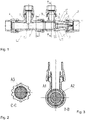
- the Figure 1 shows a schematic longitudinal sectional view of a connection fitting 1 for connecting a ring line, not shown, to a main line, also not shown.
- the connection fitting 1 has a connecting line 2, via which a first main line connection 3 and a second main line connection 4 are connected to one another in terms of flow technology within the connection fitting 1.
- the main line is connected to the connection fitting 1 in terms of flow technology via the main line connections 3 and 4.
- the ring line is connected via a first ring line connection 5 and a second ring line connection 6.
- the first ring line connection 5 is connected to the connecting line 2 via an opening 7 or opens into the connecting line 2 via the latter.
- connection fitting 1 An embodiment of the connection fitting 1 is shown, in which the first main line connection 3 and the first ring line connection 5 are each connected directly to the connecting line 2.
- the second line connection 4 and the second ring line connection 6 are each only connected indirectly, namely via a connection chamber 8, to the connection line 2 in terms of flow technology.
- a cross-sectional adjustment element 9 is arranged in terms of flow between the connecting line 2 and the connecting chamber 8. This has a plurality of tongues 10, which are elastically displaceable in the radial direction with respect to a longitudinal central axis 11 of the cross-sectional adjustment element 9, which coincides with a longitudinal central axis of the connecting line 2.
- the cross-sectional adjustment element 9 is connected to the connecting line 2 in terms of flow technology via a flow resistance element 12, preferably additionally fastened to the connecting line 2 via this.
- the flow resistance element 12 has a holding element 13 and a throttle element 14 for this purpose.
- the throttle element 14 is over the holding element 13 attached to the connecting line 2.
- the cross-sectional adjustment element 9 is connected to the connecting line 2 via the throttle element 14, which has a constant flow cross-sectional area.
- the holding element 13 of the flow resistance elements 12 is positively connected to the connecting line 2 or fastened to it, as shown here.
- the second ring line connection 6 is connected to the connecting chamber 8 in terms of flow technology via an annular space 15.
- the annular space 15 is delimited at least in regions by the connecting line 2, in particular in the radial direction inwards.
- the connecting line 2 is arranged and / or designed such that it completely engages over an opening 16 at which the second ring line connection 6 opens into the annular space 15.
- the cross-sectional adjustment element 9 is arranged completely on a side of the mouth opening 16 facing away from the first ring line connection 5.
- the cross-sectional adjustment element 9 is arranged downstream, in particular completely downstream, of the second ring line connection 6 or the outlet opening 16 with respect to a flow direction of the connecting line 2.
- the cross-sectional adjustment element 9 is particularly preferably arranged at a distance from the second ring line connection 6 or the orifice opening 16 in the flow direction, for example by a distance of at least 2.5%, at least 5%, at least 7.5% or at least 10% of an inner diameter of the connecting line 2 corresponds.
- connection fitting 1 A particularly good flow guidance in the connection fitting 1 is achieved by the conical configuration of the connecting chamber 8 shown here.
- the connecting chamber 8 is delimited on the outside by a fitting housing 17, which also delimits the annular space 15.
- the annular space 15 is delimited in the radial direction inwards by the connecting line 2 and in the radial direction outwards by the fitting housing 17, the second main line connection 4 and the orifice opening 16 being formed in the fitting housing 17.
- the Figure 2 shows a schematic cross-sectional view of the connection fitting 1 to the in the Figure 1 indicated crop marks CC.
- a flow cross-sectional area A3 of the connecting line 2 is indicated.
- the Figure 3 shows a further schematic cross-sectional view of the connection fitting 1, namely corresponding to that in FIG Figure 1 indicated cut marks BB.
- the connecting line 2 has a through-flow cross-sectional area A1
- the annular space 15 has a through-flow cross-sectional area A2.
- the flow cross-sectional areas A1 and A2 preferably correspond.
- the Figure 4 shows a further schematic longitudinal sectional view of the connection fitting 1, wherein a second flow cross-sectional area is set by means of the cross-section adjusting element 9, which is different from the first flow cross-sectional area.
- the tongues 10 are displaced outward in the radial direction with respect to the longitudinal central axis 11. This occurs automatically due to the flow through the connection fitting 1 starting from the first main line connection 4 to the second ring line connection 4.
Landscapes
- Engineering & Computer Science (AREA)
- General Engineering & Computer Science (AREA)
- Health & Medical Sciences (AREA)
- Life Sciences & Earth Sciences (AREA)
- Hydrology & Water Resources (AREA)
- Public Health (AREA)
- Water Supply & Treatment (AREA)
- Mechanical Engineering (AREA)
- Pipe Accessories (AREA)
Priority Applications (1)
| Application Number | Priority Date | Filing Date | Title |
|---|---|---|---|
| EP18191062.1A EP3617569B1 (fr) | 2018-08-28 | 2018-08-28 | Armature de raccordement ainsi que système de conduites d'eau |
Applications Claiming Priority (1)
| Application Number | Priority Date | Filing Date | Title |
|---|---|---|---|
| EP18191062.1A EP3617569B1 (fr) | 2018-08-28 | 2018-08-28 | Armature de raccordement ainsi que système de conduites d'eau |
Publications (2)
| Publication Number | Publication Date |
|---|---|
| EP3617569A1 true EP3617569A1 (fr) | 2020-03-04 |
| EP3617569B1 EP3617569B1 (fr) | 2021-02-17 |
Family
ID=63442416
Family Applications (1)
| Application Number | Title | Priority Date | Filing Date |
|---|---|---|---|
| EP18191062.1A Not-in-force EP3617569B1 (fr) | 2018-08-28 | 2018-08-28 | Armature de raccordement ainsi que système de conduites d'eau |
Country Status (1)
| Country | Link |
|---|---|
| EP (1) | EP3617569B1 (fr) |
Cited By (2)
| Publication number | Priority date | Publication date | Assignee | Title |
|---|---|---|---|---|
| EP4056768A1 (fr) | 2021-03-11 | 2022-09-14 | Gebr. Kemper GmbH + Co. KG | Installation d'eau potable |
| USD1097081S1 (en) | 2021-10-05 | 2025-10-07 | Reliance Worldwide Corporation (UK) Limited | Connector |
Citations (3)
| Publication number | Priority date | Publication date | Assignee | Title |
|---|---|---|---|---|
| EP2592191A2 (fr) | 2011-11-08 | 2013-05-15 | VIEGA GmbH & Co. KG | Élément de liaison tubulaire |
| EP2167740B1 (fr) | 2007-07-12 | 2014-09-10 | Gebr. Kemper GmbH + Co. KG Metallwerke | Armatur de raccordement et installation de distribution d'eau |
| EP2843141A1 (fr) | 2013-08-27 | 2015-03-04 | Georg Fischer Rohrleitungssysteme AG | Gicleur |
-
2018
- 2018-08-28 EP EP18191062.1A patent/EP3617569B1/fr not_active Not-in-force
Patent Citations (3)
| Publication number | Priority date | Publication date | Assignee | Title |
|---|---|---|---|---|
| EP2167740B1 (fr) | 2007-07-12 | 2014-09-10 | Gebr. Kemper GmbH + Co. KG Metallwerke | Armatur de raccordement et installation de distribution d'eau |
| EP2592191A2 (fr) | 2011-11-08 | 2013-05-15 | VIEGA GmbH & Co. KG | Élément de liaison tubulaire |
| EP2843141A1 (fr) | 2013-08-27 | 2015-03-04 | Georg Fischer Rohrleitungssysteme AG | Gicleur |
Cited By (2)
| Publication number | Priority date | Publication date | Assignee | Title |
|---|---|---|---|---|
| EP4056768A1 (fr) | 2021-03-11 | 2022-09-14 | Gebr. Kemper GmbH + Co. KG | Installation d'eau potable |
| USD1097081S1 (en) | 2021-10-05 | 2025-10-07 | Reliance Worldwide Corporation (UK) Limited | Connector |
Also Published As
| Publication number | Publication date |
|---|---|
| EP3617569B1 (fr) | 2021-02-17 |
Similar Documents
| Publication | Publication Date | Title |
|---|---|---|
| EP2167740B1 (fr) | Armatur de raccordement et installation de distribution d'eau | |
| EP2098647B1 (fr) | Armature de connection | |
| EP1516237B1 (fr) | Regulateur de debit | |
| DE102017101566B3 (de) | Schlauchanschlussanordnung, Verwendung einer Schlauchanschlussanordnung und Sanitärarmatur | |
| EP3354804A1 (fr) | Dispositif de raccord de tuyau, utilisation d'un dispositif de raccord de tuyau et armature sanitaire | |
| EP3268547A1 (fr) | Pièce insérable par ajustement serré dans une section de conduit | |
| DE102011055138B4 (de) | Rohrförmiges Verbindungselement | |
| EP3617569B1 (fr) | Armature de raccordement ainsi que système de conduites d'eau | |
| EP2710287B1 (fr) | Ensemble raccord de tuyau flexible | |
| EP3011248B1 (fr) | Dispositif permettant d'influer sur la zone de sortie d'une plaque support de tubes d'un échangeur de chaleur à faisceau de tubes | |
| EP3318683A1 (fr) | Corps distributeur de fluide et douche sanitaire | |
| WO2009003555A1 (fr) | Dispositif de répartition d'un liquide transporté au moyen d'un écoulement de gaz | |
| EP2233648A1 (fr) | Système de boisson et d'eau sanitaire | |
| EP2206939B1 (fr) | Armature | |
| EP3969975B1 (fr) | Régulateur de débit et son procédé de production | |
| EP1175576A1 (fr) | Garniture d'arrivee d'eau pour un reservoir de chasse | |
| DE10132001C2 (de) | Thermostatischer Regler zur Regelung der Durchflussmenge eines Fluids | |
| EP3366851B1 (fr) | Ensemble soupape de remplissage universel | |
| DE19743740C2 (de) | Mehrstufiger Durchflußmengenregler nach dem Elastomerring-Verformprinzip | |
| DE102017102537B4 (de) | Ventilanordnung | |
| DE102004041499B4 (de) | Absperrvorrichtung für eine Gasleitung | |
| DE10018644B4 (de) | Wasserzähler | |
| WO2023169779A1 (fr) | Vanne de réduction de pression | |
| AT397857B (de) | Anschlusseinrichtung für das anschliessen von heizkörpern | |
| DE102023105913A1 (de) | Verwendung einer Leitung, fluidische Anordnung und Sanitärarmatur |
Legal Events
| Date | Code | Title | Description |
|---|---|---|---|
| PUAI | Public reference made under article 153(3) epc to a published international application that has entered the european phase |
Free format text: ORIGINAL CODE: 0009012 |
|
| STAA | Information on the status of an ep patent application or granted ep patent |
Free format text: STATUS: THE APPLICATION HAS BEEN PUBLISHED |
|
| AK | Designated contracting states |
Kind code of ref document: A1 Designated state(s): AL AT BE BG CH CY CZ DE DK EE ES FI FR GB GR HR HU IE IS IT LI LT LU LV MC MK MT NL NO PL PT RO RS SE SI SK SM TR |
|
| AX | Request for extension of the european patent |
Extension state: BA ME |
|
| STAA | Information on the status of an ep patent application or granted ep patent |
Free format text: STATUS: REQUEST FOR EXAMINATION WAS MADE |
|
| 17P | Request for examination filed |
Effective date: 20200728 |
|
| RBV | Designated contracting states (corrected) |
Designated state(s): AL AT BE BG CH CY CZ DE DK EE ES FI FR GB GR HR HU IE IS IT LI LT LU LV MC MK MT NL NO PL PT RO RS SE SI SK SM TR |
|
| GRAP | Despatch of communication of intention to grant a patent |
Free format text: ORIGINAL CODE: EPIDOSNIGR1 |
|
| STAA | Information on the status of an ep patent application or granted ep patent |
Free format text: STATUS: GRANT OF PATENT IS INTENDED |
|
| RIC1 | Information provided on ipc code assigned before grant |
Ipc: F16L 21/00 20060101ALI20200916BHEP Ipc: F16L 41/02 20060101ALN20200916BHEP Ipc: E03B 7/09 20060101ALI20200916BHEP Ipc: E03B 7/04 20060101ALI20200916BHEP Ipc: F16K 15/14 20060101AFI20200916BHEP |
|
| INTG | Intention to grant announced |
Effective date: 20201006 |
|
| GRAS | Grant fee paid |
Free format text: ORIGINAL CODE: EPIDOSNIGR3 |
|
| GRAA | (expected) grant |
Free format text: ORIGINAL CODE: 0009210 |
|
| STAA | Information on the status of an ep patent application or granted ep patent |
Free format text: STATUS: THE PATENT HAS BEEN GRANTED |
|
| AK | Designated contracting states |
Kind code of ref document: B1 Designated state(s): AL AT BE BG CH CY CZ DE DK EE ES FI FR GB GR HR HU IE IS IT LI LT LU LV MC MK MT NL NO PL PT RO RS SE SI SK SM TR |
|
| REG | Reference to a national code |
Ref country code: GB Ref legal event code: FG4D Free format text: NOT ENGLISH |
|
| REG | Reference to a national code |
Ref country code: CH Ref legal event code: NV Representative=s name: GEORG FISCHER AG, CH Ref country code: CH Ref legal event code: EP |
|
| REG | Reference to a national code |
Ref country code: DE Ref legal event code: R096 Ref document number: 502018003888 Country of ref document: DE |
|
| REG | Reference to a national code |
Ref country code: AT Ref legal event code: REF Ref document number: 1361906 Country of ref document: AT Kind code of ref document: T Effective date: 20210315 |
|
| REG | Reference to a national code |
Ref country code: IE Ref legal event code: FG4D Free format text: LANGUAGE OF EP DOCUMENT: GERMAN |
|
| REG | Reference to a national code |
Ref country code: LT Ref legal event code: MG9D |
|
| REG | Reference to a national code |
Ref country code: NL Ref legal event code: MP Effective date: 20210217 |
|
| PG25 | Lapsed in a contracting state [announced via postgrant information from national office to epo] |
Ref country code: BG Free format text: LAPSE BECAUSE OF FAILURE TO SUBMIT A TRANSLATION OF THE DESCRIPTION OR TO PAY THE FEE WITHIN THE PRESCRIBED TIME-LIMIT Effective date: 20210517 Ref country code: HR Free format text: LAPSE BECAUSE OF FAILURE TO SUBMIT A TRANSLATION OF THE DESCRIPTION OR TO PAY THE FEE WITHIN THE PRESCRIBED TIME-LIMIT Effective date: 20210217 Ref country code: GR Free format text: LAPSE BECAUSE OF FAILURE TO SUBMIT A TRANSLATION OF THE DESCRIPTION OR TO PAY THE FEE WITHIN THE PRESCRIBED TIME-LIMIT Effective date: 20210518 Ref country code: FI Free format text: LAPSE BECAUSE OF FAILURE TO SUBMIT A TRANSLATION OF THE DESCRIPTION OR TO PAY THE FEE WITHIN THE PRESCRIBED TIME-LIMIT Effective date: 20210217 Ref country code: LT Free format text: LAPSE BECAUSE OF FAILURE TO SUBMIT A TRANSLATION OF THE DESCRIPTION OR TO PAY THE FEE WITHIN THE PRESCRIBED TIME-LIMIT Effective date: 20210217 Ref country code: PT Free format text: LAPSE BECAUSE OF FAILURE TO SUBMIT A TRANSLATION OF THE DESCRIPTION OR TO PAY THE FEE WITHIN THE PRESCRIBED TIME-LIMIT Effective date: 20210617 Ref country code: NO Free format text: LAPSE BECAUSE OF FAILURE TO SUBMIT A TRANSLATION OF THE DESCRIPTION OR TO PAY THE FEE WITHIN THE PRESCRIBED TIME-LIMIT Effective date: 20210517 |
|
| PG25 | Lapsed in a contracting state [announced via postgrant information from national office to epo] |
Ref country code: SE Free format text: LAPSE BECAUSE OF FAILURE TO SUBMIT A TRANSLATION OF THE DESCRIPTION OR TO PAY THE FEE WITHIN THE PRESCRIBED TIME-LIMIT Effective date: 20210217 Ref country code: LV Free format text: LAPSE BECAUSE OF FAILURE TO SUBMIT A TRANSLATION OF THE DESCRIPTION OR TO PAY THE FEE WITHIN THE PRESCRIBED TIME-LIMIT Effective date: 20210217 Ref country code: NL Free format text: LAPSE BECAUSE OF FAILURE TO SUBMIT A TRANSLATION OF THE DESCRIPTION OR TO PAY THE FEE WITHIN THE PRESCRIBED TIME-LIMIT Effective date: 20210217 Ref country code: PL Free format text: LAPSE BECAUSE OF FAILURE TO SUBMIT A TRANSLATION OF THE DESCRIPTION OR TO PAY THE FEE WITHIN THE PRESCRIBED TIME-LIMIT Effective date: 20210217 Ref country code: RS Free format text: LAPSE BECAUSE OF FAILURE TO SUBMIT A TRANSLATION OF THE DESCRIPTION OR TO PAY THE FEE WITHIN THE PRESCRIBED TIME-LIMIT Effective date: 20210217 |
|
| PG25 | Lapsed in a contracting state [announced via postgrant information from national office to epo] |
Ref country code: IS Free format text: LAPSE BECAUSE OF FAILURE TO SUBMIT A TRANSLATION OF THE DESCRIPTION OR TO PAY THE FEE WITHIN THE PRESCRIBED TIME-LIMIT Effective date: 20210617 |
|
| PG25 | Lapsed in a contracting state [announced via postgrant information from national office to epo] |
Ref country code: EE Free format text: LAPSE BECAUSE OF FAILURE TO SUBMIT A TRANSLATION OF THE DESCRIPTION OR TO PAY THE FEE WITHIN THE PRESCRIBED TIME-LIMIT Effective date: 20210217 Ref country code: CZ Free format text: LAPSE BECAUSE OF FAILURE TO SUBMIT A TRANSLATION OF THE DESCRIPTION OR TO PAY THE FEE WITHIN THE PRESCRIBED TIME-LIMIT Effective date: 20210217 Ref country code: SM Free format text: LAPSE BECAUSE OF FAILURE TO SUBMIT A TRANSLATION OF THE DESCRIPTION OR TO PAY THE FEE WITHIN THE PRESCRIBED TIME-LIMIT Effective date: 20210217 |
|
| REG | Reference to a national code |
Ref country code: DE Ref legal event code: R097 Ref document number: 502018003888 Country of ref document: DE |
|
| PG25 | Lapsed in a contracting state [announced via postgrant information from national office to epo] |
Ref country code: SK Free format text: LAPSE BECAUSE OF FAILURE TO SUBMIT A TRANSLATION OF THE DESCRIPTION OR TO PAY THE FEE WITHIN THE PRESCRIBED TIME-LIMIT Effective date: 20210217 Ref country code: RO Free format text: LAPSE BECAUSE OF FAILURE TO SUBMIT A TRANSLATION OF THE DESCRIPTION OR TO PAY THE FEE WITHIN THE PRESCRIBED TIME-LIMIT Effective date: 20210217 Ref country code: DK Free format text: LAPSE BECAUSE OF FAILURE TO SUBMIT A TRANSLATION OF THE DESCRIPTION OR TO PAY THE FEE WITHIN THE PRESCRIBED TIME-LIMIT Effective date: 20210217 |
|
| PGFP | Annual fee paid to national office [announced via postgrant information from national office to epo] |
Ref country code: DE Payment date: 20210819 Year of fee payment: 4 Ref country code: CH Payment date: 20210819 Year of fee payment: 4 |
|
| PLBE | No opposition filed within time limit |
Free format text: ORIGINAL CODE: 0009261 |
|
| STAA | Information on the status of an ep patent application or granted ep patent |
Free format text: STATUS: NO OPPOSITION FILED WITHIN TIME LIMIT |
|
| 26N | No opposition filed |
Effective date: 20211118 |
|
| PG25 | Lapsed in a contracting state [announced via postgrant information from national office to epo] |
Ref country code: ES Free format text: LAPSE BECAUSE OF FAILURE TO SUBMIT A TRANSLATION OF THE DESCRIPTION OR TO PAY THE FEE WITHIN THE PRESCRIBED TIME-LIMIT Effective date: 20210217 Ref country code: AL Free format text: LAPSE BECAUSE OF FAILURE TO SUBMIT A TRANSLATION OF THE DESCRIPTION OR TO PAY THE FEE WITHIN THE PRESCRIBED TIME-LIMIT Effective date: 20210217 |
|
| PG25 | Lapsed in a contracting state [announced via postgrant information from national office to epo] |
Ref country code: SI Free format text: LAPSE BECAUSE OF FAILURE TO SUBMIT A TRANSLATION OF THE DESCRIPTION OR TO PAY THE FEE WITHIN THE PRESCRIBED TIME-LIMIT Effective date: 20210217 |
|
| PG25 | Lapsed in a contracting state [announced via postgrant information from national office to epo] |
Ref country code: MC Free format text: LAPSE BECAUSE OF FAILURE TO SUBMIT A TRANSLATION OF THE DESCRIPTION OR TO PAY THE FEE WITHIN THE PRESCRIBED TIME-LIMIT Effective date: 20210217 |
|
| REG | Reference to a national code |
Ref country code: BE Ref legal event code: MM Effective date: 20210831 |
|
| PG25 | Lapsed in a contracting state [announced via postgrant information from national office to epo] |
Ref country code: IT Free format text: LAPSE BECAUSE OF FAILURE TO SUBMIT A TRANSLATION OF THE DESCRIPTION OR TO PAY THE FEE WITHIN THE PRESCRIBED TIME-LIMIT Effective date: 20210217 |
|
| PG25 | Lapsed in a contracting state [announced via postgrant information from national office to epo] |
Ref country code: IS Free format text: LAPSE BECAUSE OF FAILURE TO SUBMIT A TRANSLATION OF THE DESCRIPTION OR TO PAY THE FEE WITHIN THE PRESCRIBED TIME-LIMIT Effective date: 20210617 Ref country code: LU Free format text: LAPSE BECAUSE OF NON-PAYMENT OF DUE FEES Effective date: 20210828 |
|
| PG25 | Lapsed in a contracting state [announced via postgrant information from national office to epo] |
Ref country code: IE Free format text: LAPSE BECAUSE OF NON-PAYMENT OF DUE FEES Effective date: 20210828 Ref country code: FR Free format text: LAPSE BECAUSE OF NON-PAYMENT OF DUE FEES Effective date: 20210831 Ref country code: BE Free format text: LAPSE BECAUSE OF NON-PAYMENT OF DUE FEES Effective date: 20210831 |
|
| REG | Reference to a national code |
Ref country code: DE Ref legal event code: R119 Ref document number: 502018003888 Country of ref document: DE |
|
| REG | Reference to a national code |
Ref country code: CH Ref legal event code: PL |
|
| GBPC | Gb: european patent ceased through non-payment of renewal fee |
Effective date: 20220828 |
|
| PG25 | Lapsed in a contracting state [announced via postgrant information from national office to epo] |
Ref country code: LI Free format text: LAPSE BECAUSE OF NON-PAYMENT OF DUE FEES Effective date: 20220831 Ref country code: CH Free format text: LAPSE BECAUSE OF NON-PAYMENT OF DUE FEES Effective date: 20220831 |
|
| PG25 | Lapsed in a contracting state [announced via postgrant information from national office to epo] |
Ref country code: CY Free format text: LAPSE BECAUSE OF FAILURE TO SUBMIT A TRANSLATION OF THE DESCRIPTION OR TO PAY THE FEE WITHIN THE PRESCRIBED TIME-LIMIT Effective date: 20210217 |
|
| P01 | Opt-out of the competence of the unified patent court (upc) registered |
Effective date: 20230529 |
|
| PG25 | Lapsed in a contracting state [announced via postgrant information from national office to epo] |
Ref country code: HU Free format text: LAPSE BECAUSE OF FAILURE TO SUBMIT A TRANSLATION OF THE DESCRIPTION OR TO PAY THE FEE WITHIN THE PRESCRIBED TIME-LIMIT; INVALID AB INITIO Effective date: 20180828 Ref country code: DE Free format text: LAPSE BECAUSE OF NON-PAYMENT OF DUE FEES Effective date: 20230301 |
|
| PG25 | Lapsed in a contracting state [announced via postgrant information from national office to epo] |
Ref country code: GB Free format text: LAPSE BECAUSE OF NON-PAYMENT OF DUE FEES Effective date: 20220828 |
|
| PG25 | Lapsed in a contracting state [announced via postgrant information from national office to epo] |
Ref country code: MK Free format text: LAPSE BECAUSE OF FAILURE TO SUBMIT A TRANSLATION OF THE DESCRIPTION OR TO PAY THE FEE WITHIN THE PRESCRIBED TIME-LIMIT Effective date: 20210217 |
|
| PG25 | Lapsed in a contracting state [announced via postgrant information from national office to epo] |
Ref country code: MT Free format text: LAPSE BECAUSE OF FAILURE TO SUBMIT A TRANSLATION OF THE DESCRIPTION OR TO PAY THE FEE WITHIN THE PRESCRIBED TIME-LIMIT Effective date: 20210217 |
|
| REG | Reference to a national code |
Ref country code: AT Ref legal event code: MM01 Ref document number: 1361906 Country of ref document: AT Kind code of ref document: T Effective date: 20230828 |
|
| PG25 | Lapsed in a contracting state [announced via postgrant information from national office to epo] |
Ref country code: AT Free format text: LAPSE BECAUSE OF NON-PAYMENT OF DUE FEES Effective date: 20230828 |
|
| PG25 | Lapsed in a contracting state [announced via postgrant information from national office to epo] |
Ref country code: AT Free format text: LAPSE BECAUSE OF NON-PAYMENT OF DUE FEES Effective date: 20230828 |
|
| PG25 | Lapsed in a contracting state [announced via postgrant information from national office to epo] |
Ref country code: TR Free format text: LAPSE BECAUSE OF FAILURE TO SUBMIT A TRANSLATION OF THE DESCRIPTION OR TO PAY THE FEE WITHIN THE PRESCRIBED TIME-LIMIT Effective date: 20210217 |
|
| PGFP | Annual fee paid to national office [announced via postgrant information from national office to epo] |
Ref country code: AT Payment date: 20260410 Year of fee payment: 5 |