EP3617578A1 - Goulotte de chargement pour pierres en vrac - Google Patents
Goulotte de chargement pour pierres en vrac Download PDFInfo
- Publication number
- EP3617578A1 EP3617578A1 EP18000710.6A EP18000710A EP3617578A1 EP 3617578 A1 EP3617578 A1 EP 3617578A1 EP 18000710 A EP18000710 A EP 18000710A EP 3617578 A1 EP3617578 A1 EP 3617578A1
- Authority
- EP
- European Patent Office
- Prior art keywords
- trough
- outer pipe
- supply chute
- pipe
- chute
- Prior art date
- Legal status (The legal status is an assumption and is not a legal conclusion. Google has not performed a legal analysis and makes no representation as to the accuracy of the status listed.)
- Granted
Links
Images


Classifications
-
- F—MECHANICAL ENGINEERING; LIGHTING; HEATING; WEAPONS; BLASTING
- F16—ENGINEERING ELEMENTS AND UNITS; GENERAL MEASURES FOR PRODUCING AND MAINTAINING EFFECTIVE FUNCTIONING OF MACHINES OR INSTALLATIONS; THERMAL INSULATION IN GENERAL
- F16L—PIPES; JOINTS OR FITTINGS FOR PIPES; SUPPORTS FOR PIPES, CABLES OR PROTECTIVE TUBING; MEANS FOR THERMAL INSULATION IN GENERAL
- F16L9/00—Rigid pipes
- F16L9/02—Rigid pipes of metal
- F16L9/04—Reinforced pipes
-
- B—PERFORMING OPERATIONS; TRANSPORTING
- B65—CONVEYING; PACKING; STORING; HANDLING THIN OR FILAMENTARY MATERIAL
- B65G—TRANSPORT OR STORAGE DEVICES, e.g. CONVEYORS FOR LOADING OR TIPPING, SHOP CONVEYOR SYSTEMS OR PNEUMATIC TUBE CONVEYORS
- B65G11/00—Chutes
- B65G11/02—Chutes of straight form
- B65G11/026—Chutes of straight form for bulk
-
- B—PERFORMING OPERATIONS; TRANSPORTING
- B65—CONVEYING; PACKING; STORING; HANDLING THIN OR FILAMENTARY MATERIAL
- B65G—TRANSPORT OR STORAGE DEVICES, e.g. CONVEYORS FOR LOADING OR TIPPING, SHOP CONVEYOR SYSTEMS OR PNEUMATIC TUBE CONVEYORS
- B65G11/00—Chutes
- B65G11/16—Interior surfaces; Linings
- B65G11/166—Interior surfaces; Linings for bulk
-
- B—PERFORMING OPERATIONS; TRANSPORTING
- B65—CONVEYING; PACKING; STORING; HANDLING THIN OR FILAMENTARY MATERIAL
- B65G—TRANSPORT OR STORAGE DEVICES, e.g. CONVEYORS FOR LOADING OR TIPPING, SHOP CONVEYOR SYSTEMS OR PNEUMATIC TUBE CONVEYORS
- B65G11/00—Chutes
- B65G11/18—Supports or mountings
- B65G11/186—Supports or mountings for bulk
-
- F—MECHANICAL ENGINEERING; LIGHTING; HEATING; WEAPONS; BLASTING
- F16—ENGINEERING ELEMENTS AND UNITS; GENERAL MEASURES FOR PRODUCING AND MAINTAINING EFFECTIVE FUNCTIONING OF MACHINES OR INSTALLATIONS; THERMAL INSULATION IN GENERAL
- F16L—PIPES; JOINTS OR FITTINGS FOR PIPES; SUPPORTS FOR PIPES, CABLES OR PROTECTIVE TUBING; MEANS FOR THERMAL INSULATION IN GENERAL
- F16L57/00—Protection of pipes or objects of similar shape against external or internal damage or wear
- F16L57/06—Protection of pipes or objects of similar shape against external or internal damage or wear against wear
Definitions
- the invention relates to a chute, which suits primarily for supplying stone material into a milling machinery.
- a supply chute according to the invention is typically used in the concentrator of a mine.
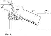
- Fig. 1 shows a principled drawing of the transfer system of stone material to a milling machinery.
- a conveyer belt BEC for stone material STM, supply box SUB, supply chute 100 and milling machinery BAM are seen in the figure.
- the end of the conveyer belt is located above the supply box so that the stone material carried by the belt drops into the supply box.
- the supply chute 100 is a wide pipe, which is mounted at a tilt e.g. at an angle of 25 degrees.
- the upper end of the pipe extends through a hole in a wall of the supply box SUB and the lower end is located inside the end of the milling machinery BAM.
- the basic part of a supply chute is typically a supply pipe made from a steel, the diameter of the pipe being in the order of 120 cm.
- the upper end of the pipe has been cut as oblique so that its cross surface is vertical, when the chute is in the use position. If the structure would comprise only the supply pipe, the stone avalanche would wear its bottom so that the whole supply pipe should be replaced quite too often.
- wearing course is made for the supply chute by coating the lower side of the inner wall of the supply pipe by thick steel plates, which stands up to wear.
- the plates are e.g. in five rows, three plates in each row.
- Each steel plate is fastened on the pipe's wall e.g. by four bolts. After bolting the steel plates further are welded together. When the steel plates are very worn, the wearing course is renewed replacing the steel plates.
- a drawback of the above-described structure is that the replacement or repair of the steel plates of the chute requires much work and time. In addition, it has to be done relatively often, in practice at six week intervals, which causes remarkable labour costs and material costs. Further a drawback is that leaks begin to occur during the use at the fastening bolts of the steel plates of the supply chute. This results in that the floor below the chute gets dirty and, due to it, continuous cleaning costs.
- a supply chute for wearing material which consists of an outer pipe and inner pipe.
- the outer pipe comprises upper and lower halves, which are fastened to each other by bolts. When the inner pipe is worn at its bottom, the bolts are loosened, the upper part of the outer pipe is removed and the inner pipe is raised and rotated so that the ridges of the outer pipe match with the next openings of the inner pipe. Then the upper part of the outer pipe is fastened again. In this way the material of the inner pipe will be utilized for the most part.
- the drawback of this solution is that the rotation of the inner pipe is time-consuming and requires heavy work.
- Figs. 2a and 2b show a supply chute for stone material known from document EP 3205921 .
- Fig. 2a shows the supply chute 200 from one side and Fig. 2b from the lower end in the direction of its axis.
- the supply chute 200 comprises an outer pipe 210 and inner pipe 220.
- the inner pipe is of wear resistent material and it is rotatable to extend the useful life.
- the outer pipe is two-part: it has an upper pipe 211 and a lower pipe 212, which are fastened to each other by bolt joints.
- a push flange 225 On the outer surface of the inner pipe 220 there is a push flange 225.
- the push flange is located between the upper flange 315 and the lower flange 316 of the outer pipe. The distance of these flanges is longer than the thickness of the push flange so that the inner pipe can be a little moved in the direction of its axis.
- the mounted inner pipe 220 rests on four support rollers with bearings, in order to make possible to rotate the inner pipe in practice.
- Fig. 2a it is seen two support rollers 241, 243 beside the outer pipe and the openings in the outer pipe for those rollers, and in Fig. 2b it is seen the lower roller pair 241, 242.
- the support rollers are fastened in pairs to the the outer pipe.
- At least two side rollers 245, 246 with bearings has been fastened to the outer surface of the lower pipe 212 of the outer pipe so that their axes are directed towards the axis of the inner pipe.
- Each side roller extends to the space between the upper and lower flange through an opening in the lower flange, towards the push flange 225 of the inner pipe.
- the inner pipe 220 is fastened to the outer pipe 210 by the same fastening bolts, by which the parts of the outer pipe has been fastened to each other.
- the inner pipe slides a little downwards in the direction of its axis and stops at its flange 225 to said side rollers 245, 246.
- the inner pipe can be rotated by the power of man, because it rests only to rollers with bearings.
- the inner pipe is rotated at a time e.g. 40 degrees to get a new wearing course, and the fastening bolts are then tightened.
- a rotation is done e.g. at six week intervals, and the whole the inner pipe has to be replaced about at a year intervals. In the production these actions cause adverse downtime.
- the object of the invention is to implement a supply chute for stone material by a new way, which reduces the maintenance costs of the supply chute.
- a supply chute according to the invention is characterized in what is set forth in the independent claim 1. Some preferred embodiments of the invention are set forth in the other claims.
- a chute supplying stone material into a mill machinery consists of an outer pipe and a supply trough on its bottom.
- the thickness of the supply trough, or trough varies on the plane of its cross section: It has highest value at the trough bottom and decreases when moving towards the sides.
- the maintenance costs of the supply chute reduce, because replacing the supply trough, by which new wearing course is arranged, is not needed to do so often than the corresponding operation in prior art. This again is due to the shaping of the trough, its relatively thick bottom part.
- the maintenance costs are reduced owing to the fact that replacing the trough is a simple and quick work.
- the invention has the advantage that no leaks occur in the supply chute according to it, the mill environment thus not becoming messy and the cleaning costs keeping lower.
- Figs. 3a, 3b and 4 show an example of the supply chute for stone material, generally any wearing hard material, according to the invention.
- the supply chute 300 is presented as longitudinal section in its use position, where its tilt angle is about 25 degrees.
- the supply chute is presented as seen from its lower end.
- Fig. 4 there is the supply trough according to Figs, 3a and 3b as perspective presentation.
- the supply chute 300 comprises an outer pipe 310, a trough 320 and a first 330 and second 340 locking plate.
- the upper end of the outer pipe has been cut oblique so that its edge matches, in the use position of the chute, the edge of the opening in the vertical wall of the supply box, as in Fig. 1 .
- the diameter d of the outer pipe is e.g. 120 cm.
- the trough 320 is e.g.of wear resistent steel or cast steel. It is located inside the outer pipe, on the bottom of the pipe. A small space remains between the trough sides and the outer pipe so that the trough can be moved in the longitudinal direction.
- the trough extends as mounted at least to the plane of both the upper and lower end of the outer pipe. The sides of the trough extend so high in the outer pipe that the wear due to the stone material running in the supply chute falls substantially only on the trough.
- the thickness of the trough varies on the plane of its cross section:
- the thickness is at its maximum at the trough bottom and decreases when moving towards the sides.
- the thickness t b in the middle of the bottom is e.g. 50-60 mm and the thickness t s of the sides is e.g. 20-30 mm.
- the thick bottom part extends remarkably the replacement interval of the wearing structure part of the supply chute. Compared with the corresponding known structure in Figs. 2a,b , the replacement interval extends about fourfold, to more than half a year.
- the trough 320 is wedge-shaped so that the height h u of its upper end is greater than the height h l of its lower end.
- the heights mean here and in the claims the heights measured on the planes parallel with a cross-section plane perpendicular to the axis of the outer pipe.
- the height hi of the lower end of the trough is about 52% of the inner diameter of the outer pipe and the height h u of the upper end of the trough is about 45% of the inner diameter of the outer pipe.
- said per cent number is typically in the range 35-50%, and regarding the height h u of the upper end typically in the range 45-60%.
- longitudinal locking plates 330, 340 are fastened to the inner surface of the outer pipe 310 so that one side edge of the mounted trough is substantially at its whole length in contact with the lower surface of the first locking plate 330 and correspondingly the other side edge is in contact with the lower surface of the second locking plate 340.
- the trough can not, owing to its wedge-shaped form, slide downwards in the outer pipe.
- Fig. 4 it is seen the second locking plate 340 drawn apart from the trough 320. Seven holes are seen in the locking plate for its fastening.
- Fig. 5 shows an example of the fastening way of the locking plates in the supply chute according to the invention.
- a part of the outer pipe 310, the second locking plate 340 and one fastening mean of this locking plate in the cross-section plane of the supply chute are seen in the figure.
- the fastening mean is a bolt BTn with its nut NTn, the bolt being located in a hole machined to the locking plate.
- the bolt extends through a respective hole in the outer pipe.
- the nut NTn outside the outer pipe tightens the locking plate 340 against the inner surface of the outer pipe.
- a trough according to the invention can be removed for the replacement simply by pulling it out of the outer pipe the upper end first.
- the fastening means of either of the locking plates are loosened, after which that locking plate cames off and the trough can move downwards out of the pipe.
- the replacement of the trough is a quick and simple work compared with corresponding operation in the supply chute structures being in use.
- the qualifiers 'upper' and 'lower' refer to the use position of the supply chute and have then nothing to do with the storing and transport positions of the chute parts.
- the 'longitudinal direction' again means the direction of the axis of the outer pipe with a certain accuracy.
- a supply chute for stone material according to the invention has been described above. However, in details its structure can differ from that presented.
- the locking plates can be fastened by clamps at the ends of the outer pipe, or by locking hinge.
- the inventive idea can be applied in different ways within the scope set by the independent claim 1.
Landscapes
- Engineering & Computer Science (AREA)
- General Engineering & Computer Science (AREA)
- Mechanical Engineering (AREA)
- Chutes (AREA)
Priority Applications (1)
| Application Number | Priority Date | Filing Date | Title |
|---|---|---|---|
| EP18000710.6A EP3617578B1 (fr) | 2018-08-31 | 2018-08-31 | Goulotte de chargement pour pierres en vrac |
Applications Claiming Priority (1)
| Application Number | Priority Date | Filing Date | Title |
|---|---|---|---|
| EP18000710.6A EP3617578B1 (fr) | 2018-08-31 | 2018-08-31 | Goulotte de chargement pour pierres en vrac |
Publications (2)
| Publication Number | Publication Date |
|---|---|
| EP3617578A1 true EP3617578A1 (fr) | 2020-03-04 |
| EP3617578B1 EP3617578B1 (fr) | 2021-06-09 |
Family
ID=63490139
Family Applications (1)
| Application Number | Title | Priority Date | Filing Date |
|---|---|---|---|
| EP18000710.6A Active EP3617578B1 (fr) | 2018-08-31 | 2018-08-31 | Goulotte de chargement pour pierres en vrac |
Country Status (1)
| Country | Link |
|---|---|
| EP (1) | EP3617578B1 (fr) |
Citations (6)
| Publication number | Priority date | Publication date | Assignee | Title |
|---|---|---|---|---|
| DE510324C (de) * | 1929-12-08 | 1930-10-18 | Otto Nootbaar | Rohrleitung mit Ausfuetterung zum Transport von Schuettgut |
| GB770413A (en) * | 1952-12-02 | 1957-03-20 | Oskar Biegel G M B H | Improvements in or relating to pipe elbows for pneumatic and hydraulic conveyor pipelines |
| DE970779C (de) | 1953-09-15 | 1958-10-30 | Esser Werke Vorm Westmontan We | Foerderrohr fuer insbesondere in stark geneigter Richtung verlaufende Schuettgut-Foerderleitungen |
| DE4404638A1 (de) * | 1993-02-15 | 1994-08-18 | Kobe Steel Ltd | Walzenmühle |
| EP3205921A1 (fr) | 2016-02-11 | 2017-08-16 | lin konepaja Oy | Goulotte d'alimentation pour un matériau pierreux |
| EP3270029A1 (fr) * | 2015-03-12 | 2018-01-17 | Zhaohui Zhou | Tube résistant à l'usure et aux chocs, à deux couches, du type à deux branches ou à plusieurs branches et procédé de fabrication de celui-ci |
-
2018
- 2018-08-31 EP EP18000710.6A patent/EP3617578B1/fr active Active
Patent Citations (6)
| Publication number | Priority date | Publication date | Assignee | Title |
|---|---|---|---|---|
| DE510324C (de) * | 1929-12-08 | 1930-10-18 | Otto Nootbaar | Rohrleitung mit Ausfuetterung zum Transport von Schuettgut |
| GB770413A (en) * | 1952-12-02 | 1957-03-20 | Oskar Biegel G M B H | Improvements in or relating to pipe elbows for pneumatic and hydraulic conveyor pipelines |
| DE970779C (de) | 1953-09-15 | 1958-10-30 | Esser Werke Vorm Westmontan We | Foerderrohr fuer insbesondere in stark geneigter Richtung verlaufende Schuettgut-Foerderleitungen |
| DE4404638A1 (de) * | 1993-02-15 | 1994-08-18 | Kobe Steel Ltd | Walzenmühle |
| EP3270029A1 (fr) * | 2015-03-12 | 2018-01-17 | Zhaohui Zhou | Tube résistant à l'usure et aux chocs, à deux couches, du type à deux branches ou à plusieurs branches et procédé de fabrication de celui-ci |
| EP3205921A1 (fr) | 2016-02-11 | 2017-08-16 | lin konepaja Oy | Goulotte d'alimentation pour un matériau pierreux |
Also Published As
| Publication number | Publication date |
|---|---|
| EP3617578B1 (fr) | 2021-06-09 |
Similar Documents
| Publication | Publication Date | Title |
|---|---|---|
| RU2491383C2 (ru) | Выбрасыватель или выбрасывающий узел дорожно-фрезерной машины или т.п. | |
| CN108526226A (zh) | 一种步进式冷床轧件对齐装置 | |
| US20130221143A1 (en) | Mobile sizing station | |
| US2818954A (en) | Side guide for conveyors | |
| US6244428B1 (en) | Conveyor belt maintenance specialty tools | |
| CA2916965C (fr) | Appareil d'usure pour rouleaux de meulage et procedes associes | |
| US5027940A (en) | Conveyor stub idler apparatus | |
| EP3617578B1 (fr) | Goulotte de chargement pour pierres en vrac | |
| US5908102A (en) | High capacity and easy to maintain insert for cooling bed plate transfer grid | |
| US20150151916A1 (en) | Flow-retarding chutes and spouts and method for delivering dry bulk free-flowing material to a location | |
| EP3205921B1 (fr) | Goulotte d'alimentation pour un matériau pierreux | |
| CN216813431U (zh) | 一种盲孔、深孔内壁检测、清理设备的便携支撑装置 | |
| JP6721997B2 (ja) | キャリアローラー交換用治具及びキャリアローラー交換方法 | |
| CN201746091U (zh) | 落点可调式导料管 | |
| US3261453A (en) | Helical storage unit | |
| CN217478394U (zh) | 一种棒材上料装置 | |
| CN219408164U (zh) | 一种型材送料机构 | |
| US4243131A (en) | Conveying apparatus | |
| CN219408045U (zh) | 一种容易更换的装船机抛料装置 | |
| CN222646980U (zh) | 一种方便操作的皮带机漏斗调料挡板的调节装置 | |
| CN216188499U (zh) | 一种可张紧的定量给料机 | |
| CN223188386U (zh) | 一种下料斗防积料以及调整落料点的装置 | |
| CN205045346U (zh) | 一种轴向中心可调式输送辊道 | |
| CN224198601U (zh) | 一种输煤系统免维护正料辅助装置 | |
| EP0005019A1 (fr) | Appareil de transport |
Legal Events
| Date | Code | Title | Description |
|---|---|---|---|
| PUAI | Public reference made under article 153(3) epc to a published international application that has entered the european phase |
Free format text: ORIGINAL CODE: 0009012 |
|
| STAA | Information on the status of an ep patent application or granted ep patent |
Free format text: STATUS: REQUEST FOR EXAMINATION WAS MADE |
|
| 17P | Request for examination filed |
Effective date: 20190530 |
|
| AK | Designated contracting states |
Kind code of ref document: A1 Designated state(s): AL AT BE BG CH CY CZ DE DK EE ES FI FR GB GR HR HU IE IS IT LI LT LU LV MC MK MT NL NO PL PT RO RS SE SI SK SM TR |
|
| AX | Request for extension of the european patent |
Extension state: BA ME |
|
| GRAP | Despatch of communication of intention to grant a patent |
Free format text: ORIGINAL CODE: EPIDOSNIGR1 |
|
| STAA | Information on the status of an ep patent application or granted ep patent |
Free format text: STATUS: GRANT OF PATENT IS INTENDED |
|
| RIC1 | Information provided on ipc code assigned before grant |
Ipc: F16L 57/06 20060101AFI20200407BHEP Ipc: B65G 11/16 20060101ALI20200407BHEP Ipc: F16L 9/04 20060101ALI20200407BHEP Ipc: B65G 11/02 20060101ALI20200407BHEP Ipc: B65G 11/18 20060101ALI20200407BHEP |
|
| INTG | Intention to grant announced |
Effective date: 20200423 |
|
| GRAJ | Information related to disapproval of communication of intention to grant by the applicant or resumption of examination proceedings by the epo deleted |
Free format text: ORIGINAL CODE: EPIDOSDIGR1 |
|
| GRAS | Grant fee paid |
Free format text: ORIGINAL CODE: EPIDOSNIGR3 |
|
| GRAJ | Information related to disapproval of communication of intention to grant by the applicant or resumption of examination proceedings by the epo deleted |
Free format text: ORIGINAL CODE: EPIDOSDIGR1 |
|
| GRAL | Information related to payment of fee for publishing/printing deleted |
Free format text: ORIGINAL CODE: EPIDOSDIGR3 |
|
| STAA | Information on the status of an ep patent application or granted ep patent |
Free format text: STATUS: REQUEST FOR EXAMINATION WAS MADE |
|
| INTG | Intention to grant announced |
Effective date: 20200423 |
|
| INTC | Intention to grant announced (deleted) | ||
| STAA | Information on the status of an ep patent application or granted ep patent |
Free format text: STATUS: EXAMINATION IS IN PROGRESS |
|
| 17Q | First examination report despatched |
Effective date: 20200827 |
|
| GRAP | Despatch of communication of intention to grant a patent |
Free format text: ORIGINAL CODE: EPIDOSNIGR1 |
|
| STAA | Information on the status of an ep patent application or granted ep patent |
Free format text: STATUS: GRANT OF PATENT IS INTENDED |
|
| INTG | Intention to grant announced |
Effective date: 20210302 |
|
| GRAA | (expected) grant |
Free format text: ORIGINAL CODE: 0009210 |
|
| STAA | Information on the status of an ep patent application or granted ep patent |
Free format text: STATUS: THE PATENT HAS BEEN GRANTED |
|
| AK | Designated contracting states |
Kind code of ref document: B1 Designated state(s): AL AT BE BG CH CY CZ DE DK EE ES FI FR GB GR HR HU IE IS IT LI LT LU LV MC MK MT NL NO PL PT RO RS SE SI SK SM TR |
|
| REG | Reference to a national code |
Ref country code: GB Ref legal event code: FG4D |
|
| REG | Reference to a national code |
Ref country code: CH Ref legal event code: EP Ref country code: AT Ref legal event code: REF Ref document number: 1400796 Country of ref document: AT Kind code of ref document: T Effective date: 20210615 |
|
| REG | Reference to a national code |
Ref country code: DE Ref legal event code: R096 Ref document number: 602018018207 Country of ref document: DE |
|
| REG | Reference to a national code |
Ref country code: IE Ref legal event code: FG4D |
|
| REG | Reference to a national code |
Ref country code: LT Ref legal event code: MG9D |
|
| PG25 | Lapsed in a contracting state [announced via postgrant information from national office to epo] |
Ref country code: FI Free format text: LAPSE BECAUSE OF FAILURE TO SUBMIT A TRANSLATION OF THE DESCRIPTION OR TO PAY THE FEE WITHIN THE PRESCRIBED TIME-LIMIT Effective date: 20210609 Ref country code: LT Free format text: LAPSE BECAUSE OF FAILURE TO SUBMIT A TRANSLATION OF THE DESCRIPTION OR TO PAY THE FEE WITHIN THE PRESCRIBED TIME-LIMIT Effective date: 20210609 Ref country code: BG Free format text: LAPSE BECAUSE OF FAILURE TO SUBMIT A TRANSLATION OF THE DESCRIPTION OR TO PAY THE FEE WITHIN THE PRESCRIBED TIME-LIMIT Effective date: 20210909 Ref country code: HR Free format text: LAPSE BECAUSE OF FAILURE TO SUBMIT A TRANSLATION OF THE DESCRIPTION OR TO PAY THE FEE WITHIN THE PRESCRIBED TIME-LIMIT Effective date: 20210609 |
|
| REG | Reference to a national code |
Ref country code: AT Ref legal event code: MK05 Ref document number: 1400796 Country of ref document: AT Kind code of ref document: T Effective date: 20210609 |
|
| REG | Reference to a national code |
Ref country code: NL Ref legal event code: MP Effective date: 20210609 |
|
| PG25 | Lapsed in a contracting state [announced via postgrant information from national office to epo] |
Ref country code: LV Free format text: LAPSE BECAUSE OF FAILURE TO SUBMIT A TRANSLATION OF THE DESCRIPTION OR TO PAY THE FEE WITHIN THE PRESCRIBED TIME-LIMIT Effective date: 20210609 Ref country code: NO Free format text: LAPSE BECAUSE OF FAILURE TO SUBMIT A TRANSLATION OF THE DESCRIPTION OR TO PAY THE FEE WITHIN THE PRESCRIBED TIME-LIMIT Effective date: 20210909 Ref country code: SE Free format text: LAPSE BECAUSE OF FAILURE TO SUBMIT A TRANSLATION OF THE DESCRIPTION OR TO PAY THE FEE WITHIN THE PRESCRIBED TIME-LIMIT Effective date: 20210609 Ref country code: RS Free format text: LAPSE BECAUSE OF FAILURE TO SUBMIT A TRANSLATION OF THE DESCRIPTION OR TO PAY THE FEE WITHIN THE PRESCRIBED TIME-LIMIT Effective date: 20210609 Ref country code: GR Free format text: LAPSE BECAUSE OF FAILURE TO SUBMIT A TRANSLATION OF THE DESCRIPTION OR TO PAY THE FEE WITHIN THE PRESCRIBED TIME-LIMIT Effective date: 20210910 |
|
| PG25 | Lapsed in a contracting state [announced via postgrant information from national office to epo] |
Ref country code: EE Free format text: LAPSE BECAUSE OF FAILURE TO SUBMIT A TRANSLATION OF THE DESCRIPTION OR TO PAY THE FEE WITHIN THE PRESCRIBED TIME-LIMIT Effective date: 20210609 Ref country code: ES Free format text: LAPSE BECAUSE OF FAILURE TO SUBMIT A TRANSLATION OF THE DESCRIPTION OR TO PAY THE FEE WITHIN THE PRESCRIBED TIME-LIMIT Effective date: 20210609 Ref country code: SM Free format text: LAPSE BECAUSE OF FAILURE TO SUBMIT A TRANSLATION OF THE DESCRIPTION OR TO PAY THE FEE WITHIN THE PRESCRIBED TIME-LIMIT Effective date: 20210609 Ref country code: SK Free format text: LAPSE BECAUSE OF FAILURE TO SUBMIT A TRANSLATION OF THE DESCRIPTION OR TO PAY THE FEE WITHIN THE PRESCRIBED TIME-LIMIT Effective date: 20210609 Ref country code: AT Free format text: LAPSE BECAUSE OF FAILURE TO SUBMIT A TRANSLATION OF THE DESCRIPTION OR TO PAY THE FEE WITHIN THE PRESCRIBED TIME-LIMIT Effective date: 20210609 Ref country code: CZ Free format text: LAPSE BECAUSE OF FAILURE TO SUBMIT A TRANSLATION OF THE DESCRIPTION OR TO PAY THE FEE WITHIN THE PRESCRIBED TIME-LIMIT Effective date: 20210609 Ref country code: RO Free format text: LAPSE BECAUSE OF FAILURE TO SUBMIT A TRANSLATION OF THE DESCRIPTION OR TO PAY THE FEE WITHIN THE PRESCRIBED TIME-LIMIT Effective date: 20210609 Ref country code: PT Free format text: LAPSE BECAUSE OF FAILURE TO SUBMIT A TRANSLATION OF THE DESCRIPTION OR TO PAY THE FEE WITHIN THE PRESCRIBED TIME-LIMIT Effective date: 20211011 Ref country code: NL Free format text: LAPSE BECAUSE OF FAILURE TO SUBMIT A TRANSLATION OF THE DESCRIPTION OR TO PAY THE FEE WITHIN THE PRESCRIBED TIME-LIMIT Effective date: 20210609 |
|
| PG25 | Lapsed in a contracting state [announced via postgrant information from national office to epo] |
Ref country code: PL Free format text: LAPSE BECAUSE OF FAILURE TO SUBMIT A TRANSLATION OF THE DESCRIPTION OR TO PAY THE FEE WITHIN THE PRESCRIBED TIME-LIMIT Effective date: 20210609 |
|
| REG | Reference to a national code |
Ref country code: DE Ref legal event code: R119 Ref document number: 602018018207 Country of ref document: DE |
|
| REG | Reference to a national code |
Ref country code: CH Ref legal event code: PL |
|
| PG25 | Lapsed in a contracting state [announced via postgrant information from national office to epo] |
Ref country code: MC Free format text: LAPSE BECAUSE OF FAILURE TO SUBMIT A TRANSLATION OF THE DESCRIPTION OR TO PAY THE FEE WITHIN THE PRESCRIBED TIME-LIMIT Effective date: 20210609 |
|
| PLBE | No opposition filed within time limit |
Free format text: ORIGINAL CODE: 0009261 |
|
| STAA | Information on the status of an ep patent application or granted ep patent |
Free format text: STATUS: NO OPPOSITION FILED WITHIN TIME LIMIT |
|
| REG | Reference to a national code |
Ref country code: BE Ref legal event code: MM Effective date: 20210831 |
|
| PG25 | Lapsed in a contracting state [announced via postgrant information from national office to epo] |
Ref country code: LI Free format text: LAPSE BECAUSE OF NON-PAYMENT OF DUE FEES Effective date: 20210831 Ref country code: DK Free format text: LAPSE BECAUSE OF FAILURE TO SUBMIT A TRANSLATION OF THE DESCRIPTION OR TO PAY THE FEE WITHIN THE PRESCRIBED TIME-LIMIT Effective date: 20210609 Ref country code: CH Free format text: LAPSE BECAUSE OF NON-PAYMENT OF DUE FEES Effective date: 20210831 |
|
| 26N | No opposition filed |
Effective date: 20220310 |
|
| PG25 | Lapsed in a contracting state [announced via postgrant information from national office to epo] |
Ref country code: LU Free format text: LAPSE BECAUSE OF NON-PAYMENT OF DUE FEES Effective date: 20210831 Ref country code: AL Free format text: LAPSE BECAUSE OF FAILURE TO SUBMIT A TRANSLATION OF THE DESCRIPTION OR TO PAY THE FEE WITHIN THE PRESCRIBED TIME-LIMIT Effective date: 20210609 |
|
| PG25 | Lapsed in a contracting state [announced via postgrant information from national office to epo] |
Ref country code: IT Free format text: LAPSE BECAUSE OF FAILURE TO SUBMIT A TRANSLATION OF THE DESCRIPTION OR TO PAY THE FEE WITHIN THE PRESCRIBED TIME-LIMIT Effective date: 20210609 Ref country code: IE Free format text: LAPSE BECAUSE OF NON-PAYMENT OF DUE FEES Effective date: 20210831 Ref country code: FR Free format text: LAPSE BECAUSE OF NON-PAYMENT OF DUE FEES Effective date: 20210831 Ref country code: DE Free format text: LAPSE BECAUSE OF NON-PAYMENT OF DUE FEES Effective date: 20220301 Ref country code: BE Free format text: LAPSE BECAUSE OF NON-PAYMENT OF DUE FEES Effective date: 20210831 |
|
| GBPC | Gb: european patent ceased through non-payment of renewal fee |
Effective date: 20220831 |
|
| PG25 | Lapsed in a contracting state [announced via postgrant information from national office to epo] |
Ref country code: CY Free format text: LAPSE BECAUSE OF FAILURE TO SUBMIT A TRANSLATION OF THE DESCRIPTION OR TO PAY THE FEE WITHIN THE PRESCRIBED TIME-LIMIT Effective date: 20210609 |
|
| PG25 | Lapsed in a contracting state [announced via postgrant information from national office to epo] |
Ref country code: HU Free format text: LAPSE BECAUSE OF FAILURE TO SUBMIT A TRANSLATION OF THE DESCRIPTION OR TO PAY THE FEE WITHIN THE PRESCRIBED TIME-LIMIT; INVALID AB INITIO Effective date: 20180831 |
|
| PG25 | Lapsed in a contracting state [announced via postgrant information from national office to epo] |
Ref country code: GB Free format text: LAPSE BECAUSE OF NON-PAYMENT OF DUE FEES Effective date: 20220831 |
|
| PG25 | Lapsed in a contracting state [announced via postgrant information from national office to epo] |
Ref country code: MK Free format text: LAPSE BECAUSE OF FAILURE TO SUBMIT A TRANSLATION OF THE DESCRIPTION OR TO PAY THE FEE WITHIN THE PRESCRIBED TIME-LIMIT Effective date: 20210609 |
|
| PG25 | Lapsed in a contracting state [announced via postgrant information from national office to epo] |
Ref country code: MT Free format text: LAPSE BECAUSE OF FAILURE TO SUBMIT A TRANSLATION OF THE DESCRIPTION OR TO PAY THE FEE WITHIN THE PRESCRIBED TIME-LIMIT Effective date: 20210609 |
|
| PG25 | Lapsed in a contracting state [announced via postgrant information from national office to epo] |
Ref country code: TR Free format text: LAPSE BECAUSE OF FAILURE TO SUBMIT A TRANSLATION OF THE DESCRIPTION OR TO PAY THE FEE WITHIN THE PRESCRIBED TIME-LIMIT Effective date: 20210609 |