EP3617606B1 - Système de ventilation - Google Patents
Système de ventilation Download PDFInfo
- Publication number
- EP3617606B1 EP3617606B1 EP18809173.0A EP18809173A EP3617606B1 EP 3617606 B1 EP3617606 B1 EP 3617606B1 EP 18809173 A EP18809173 A EP 18809173A EP 3617606 B1 EP3617606 B1 EP 3617606B1
- Authority
- EP
- European Patent Office
- Prior art keywords
- air
- passage
- permeable film
- indoor
- space
- Prior art date
- Legal status (The legal status is an assumption and is not a legal conclusion. Google has not performed a legal analysis and makes no representation as to the accuracy of the status listed.)
- Active
Links
Images






Classifications
-
- F—MECHANICAL ENGINEERING; LIGHTING; HEATING; WEAPONS; BLASTING
- F24—HEATING; RANGES; VENTILATING
- F24F—AIR-CONDITIONING; AIR-HUMIDIFICATION; VENTILATION; USE OF AIR CURRENTS FOR SCREENING
- F24F7/00—Ventilation
- F24F7/003—Ventilation in combination with air cleaning
-
- F—MECHANICAL ENGINEERING; LIGHTING; HEATING; WEAPONS; BLASTING
- F24—HEATING; RANGES; VENTILATING
- F24F—AIR-CONDITIONING; AIR-HUMIDIFICATION; VENTILATION; USE OF AIR CURRENTS FOR SCREENING
- F24F7/00—Ventilation
- F24F7/04—Ventilation with ducting systems, e.g. by double walls; with natural circulation
- F24F7/06—Ventilation with ducting systems, e.g. by double walls; with natural circulation with forced air circulation, e.g. by fan positioning of a ventilator in or against a conduit
-
- B—PERFORMING OPERATIONS; TRANSPORTING
- B01—PHYSICAL OR CHEMICAL PROCESSES OR APPARATUS IN GENERAL
- B01D—SEPARATION
- B01D53/00—Separation of gases or vapours; Recovering vapours of volatile solvents from gases; Chemical or biological purification of waste gases, e.g. engine exhaust gases, smoke, fumes, flue gases, aerosols
- B01D53/22—Separation of gases or vapours; Recovering vapours of volatile solvents from gases; Chemical or biological purification of waste gases, e.g. engine exhaust gases, smoke, fumes, flue gases, aerosols by diffusion
-
- B—PERFORMING OPERATIONS; TRANSPORTING
- B01—PHYSICAL OR CHEMICAL PROCESSES OR APPARATUS IN GENERAL
- B01D—SEPARATION
- B01D53/00—Separation of gases or vapours; Recovering vapours of volatile solvents from gases; Chemical or biological purification of waste gases, e.g. engine exhaust gases, smoke, fumes, flue gases, aerosols
- B01D53/26—Drying gases or vapours
-
- B—PERFORMING OPERATIONS; TRANSPORTING
- B01—PHYSICAL OR CHEMICAL PROCESSES OR APPARATUS IN GENERAL
- B01D—SEPARATION
- B01D53/00—Separation of gases or vapours; Recovering vapours of volatile solvents from gases; Chemical or biological purification of waste gases, e.g. engine exhaust gases, smoke, fumes, flue gases, aerosols
- B01D53/30—Controlling by gas-analysis apparatus
-
- F—MECHANICAL ENGINEERING; LIGHTING; HEATING; WEAPONS; BLASTING
- F24—HEATING; RANGES; VENTILATING
- F24F—AIR-CONDITIONING; AIR-HUMIDIFICATION; VENTILATION; USE OF AIR CURRENTS FOR SCREENING
- F24F11/00—Control or safety arrangements
- F24F11/0001—Control or safety arrangements for ventilation
-
- F—MECHANICAL ENGINEERING; LIGHTING; HEATING; WEAPONS; BLASTING
- F24—HEATING; RANGES; VENTILATING
- F24F—AIR-CONDITIONING; AIR-HUMIDIFICATION; VENTILATION; USE OF AIR CURRENTS FOR SCREENING
- F24F6/00—Air-humidification, e.g. cooling by humidification
-
- F—MECHANICAL ENGINEERING; LIGHTING; HEATING; WEAPONS; BLASTING
- F24—HEATING; RANGES; VENTILATING
- F24F—AIR-CONDITIONING; AIR-HUMIDIFICATION; VENTILATION; USE OF AIR CURRENTS FOR SCREENING
- F24F7/00—Ventilation
- F24F7/007—Ventilation with forced flow
-
- F—MECHANICAL ENGINEERING; LIGHTING; HEATING; WEAPONS; BLASTING
- F24—HEATING; RANGES; VENTILATING
- F24F—AIR-CONDITIONING; AIR-HUMIDIFICATION; VENTILATION; USE OF AIR CURRENTS FOR SCREENING
- F24F7/00—Ventilation
- F24F7/04—Ventilation with ducting systems, e.g. by double walls; with natural circulation
- F24F7/06—Ventilation with ducting systems, e.g. by double walls; with natural circulation with forced air circulation, e.g. by fan positioning of a ventilator in or against a conduit
- F24F7/08—Ventilation with ducting systems, e.g. by double walls; with natural circulation with forced air circulation, e.g. by fan positioning of a ventilator in or against a conduit with separate ducts for supplied and exhausted air with provisions for reversal of the input and output systems
-
- F—MECHANICAL ENGINEERING; LIGHTING; HEATING; WEAPONS; BLASTING
- F24—HEATING; RANGES; VENTILATING
- F24F—AIR-CONDITIONING; AIR-HUMIDIFICATION; VENTILATION; USE OF AIR CURRENTS FOR SCREENING
- F24F8/00—Treatment, e.g. purification, of air supplied to human living or working spaces otherwise than by heating, cooling, humidifying or drying
- F24F8/10—Treatment, e.g. purification, of air supplied to human living or working spaces otherwise than by heating, cooling, humidifying or drying by separation, e.g. by filtering
-
- F—MECHANICAL ENGINEERING; LIGHTING; HEATING; WEAPONS; BLASTING
- F24—HEATING; RANGES; VENTILATING
- F24F—AIR-CONDITIONING; AIR-HUMIDIFICATION; VENTILATION; USE OF AIR CURRENTS FOR SCREENING
- F24F8/00—Treatment, e.g. purification, of air supplied to human living or working spaces otherwise than by heating, cooling, humidifying or drying
- F24F8/10—Treatment, e.g. purification, of air supplied to human living or working spaces otherwise than by heating, cooling, humidifying or drying by separation, e.g. by filtering
- F24F8/15—Treatment, e.g. purification, of air supplied to human living or working spaces otherwise than by heating, cooling, humidifying or drying by separation, e.g. by filtering by chemical means
-
- F—MECHANICAL ENGINEERING; LIGHTING; HEATING; WEAPONS; BLASTING
- F24—HEATING; RANGES; VENTILATING
- F24F—AIR-CONDITIONING; AIR-HUMIDIFICATION; VENTILATION; USE OF AIR CURRENTS FOR SCREENING
- F24F8/00—Treatment, e.g. purification, of air supplied to human living or working spaces otherwise than by heating, cooling, humidifying or drying
- F24F8/10—Treatment, e.g. purification, of air supplied to human living or working spaces otherwise than by heating, cooling, humidifying or drying by separation, e.g. by filtering
- F24F8/15—Treatment, e.g. purification, of air supplied to human living or working spaces otherwise than by heating, cooling, humidifying or drying by separation, e.g. by filtering by chemical means
- F24F8/158—Treatment, e.g. purification, of air supplied to human living or working spaces otherwise than by heating, cooling, humidifying or drying by separation, e.g. by filtering by chemical means using active carbon
-
- B—PERFORMING OPERATIONS; TRANSPORTING
- B01—PHYSICAL OR CHEMICAL PROCESSES OR APPARATUS IN GENERAL
- B01D—SEPARATION
- B01D53/00—Separation of gases or vapours; Recovering vapours of volatile solvents from gases; Chemical or biological purification of waste gases, e.g. engine exhaust gases, smoke, fumes, flue gases, aerosols
- B01D53/22—Separation of gases or vapours; Recovering vapours of volatile solvents from gases; Chemical or biological purification of waste gases, e.g. engine exhaust gases, smoke, fumes, flue gases, aerosols by diffusion
- B01D2053/221—Devices
-
- F—MECHANICAL ENGINEERING; LIGHTING; HEATING; WEAPONS; BLASTING
- F24—HEATING; RANGES; VENTILATING
- F24F—AIR-CONDITIONING; AIR-HUMIDIFICATION; VENTILATION; USE OF AIR CURRENTS FOR SCREENING
- F24F7/00—Ventilation
- F24F2007/001—Ventilation with exhausting air ducts
-
- F—MECHANICAL ENGINEERING; LIGHTING; HEATING; WEAPONS; BLASTING
- F24—HEATING; RANGES; VENTILATING
- F24F—AIR-CONDITIONING; AIR-HUMIDIFICATION; VENTILATION; USE OF AIR CURRENTS FOR SCREENING
- F24F7/00—Ventilation
- F24F2007/0025—Ventilation using vent ports in a wall
-
- F—MECHANICAL ENGINEERING; LIGHTING; HEATING; WEAPONS; BLASTING
- F24—HEATING; RANGES; VENTILATING
- F24F—AIR-CONDITIONING; AIR-HUMIDIFICATION; VENTILATION; USE OF AIR CURRENTS FOR SCREENING
- F24F2110/00—Control inputs relating to air properties
- F24F2110/50—Air quality properties
- F24F2110/65—Concentration of specific substances or contaminants
- F24F2110/66—Volatile organic compounds [VOC]
-
- F—MECHANICAL ENGINEERING; LIGHTING; HEATING; WEAPONS; BLASTING
- F24—HEATING; RANGES; VENTILATING
- F24F—AIR-CONDITIONING; AIR-HUMIDIFICATION; VENTILATION; USE OF AIR CURRENTS FOR SCREENING
- F24F2110/00—Control inputs relating to air properties
- F24F2110/50—Air quality properties
- F24F2110/65—Concentration of specific substances or contaminants
- F24F2110/70—Carbon dioxide
-
- F—MECHANICAL ENGINEERING; LIGHTING; HEATING; WEAPONS; BLASTING
- F24—HEATING; RANGES; VENTILATING
- F24F—AIR-CONDITIONING; AIR-HUMIDIFICATION; VENTILATION; USE OF AIR CURRENTS FOR SCREENING
- F24F2203/00—Devices or apparatus used for air treatment
- F24F2203/10—Rotary wheel
- F24F2203/1024—Rotary wheel combined with a humidifier
-
- F—MECHANICAL ENGINEERING; LIGHTING; HEATING; WEAPONS; BLASTING
- F24—HEATING; RANGES; VENTILATING
- F24F—AIR-CONDITIONING; AIR-HUMIDIFICATION; VENTILATION; USE OF AIR CURRENTS FOR SCREENING
- F24F2203/00—Devices or apparatus used for air treatment
- F24F2203/10—Rotary wheel
- F24F2203/1032—Desiccant wheel
-
- F—MECHANICAL ENGINEERING; LIGHTING; HEATING; WEAPONS; BLASTING
- F24—HEATING; RANGES; VENTILATING
- F24F—AIR-CONDITIONING; AIR-HUMIDIFICATION; VENTILATION; USE OF AIR CURRENTS FOR SCREENING
- F24F6/00—Air-humidification, e.g. cooling by humidification
- F24F6/02—Air-humidification, e.g. cooling by humidification by evaporation of water in the air
- F24F6/04—Air-humidification, e.g. cooling by humidification by evaporation of water in the air using stationary unheated wet elements
-
- F—MECHANICAL ENGINEERING; LIGHTING; HEATING; WEAPONS; BLASTING
- F24—HEATING; RANGES; VENTILATING
- F24F—AIR-CONDITIONING; AIR-HUMIDIFICATION; VENTILATION; USE OF AIR CURRENTS FOR SCREENING
- F24F6/00—Air-humidification, e.g. cooling by humidification
- F24F6/02—Air-humidification, e.g. cooling by humidification by evaporation of water in the air
- F24F6/06—Air-humidification, e.g. cooling by humidification by evaporation of water in the air using moving unheated wet elements
-
- Y—GENERAL TAGGING OF NEW TECHNOLOGICAL DEVELOPMENTS; GENERAL TAGGING OF CROSS-SECTIONAL TECHNOLOGIES SPANNING OVER SEVERAL SECTIONS OF THE IPC; TECHNICAL SUBJECTS COVERED BY FORMER USPC CROSS-REFERENCE ART COLLECTIONS [XRACs] AND DIGESTS
- Y02—TECHNOLOGIES OR APPLICATIONS FOR MITIGATION OR ADAPTATION AGAINST CLIMATE CHANGE
- Y02C—CAPTURE, STORAGE, SEQUESTRATION OR DISPOSAL OF GREENHOUSE GASES [GHG]
- Y02C20/00—Capture or disposal of greenhouse gases
- Y02C20/40—Capture or disposal of greenhouse gases of CO2
Definitions
- the present invention relates to a ventilation system.
- Patent Literature 1 discloses a ventilation system that removes carbon dioxide while causing indoor air to circulate.
- the ventilation system includes an inside air passage into which indoor air in an indoor space to be ventilated is introduced and that allows the indoor air to recirculate into the indoor space.
- a carbon-dioxide removing device is provided in the inside air passage.
- the carbon-dioxide removing device contains a chemical agent (such as a liquid amine type, a solid amine type, or activated carbon) for absorbing or adsorbing a target gas.
- a chemical agent such as a liquid amine type, a solid amine type, or activated carbon
- the indoor air passes through the carbon-dioxide removing device, the carbon dioxide in the indoor air is absorbed or adsorbed by the chemical agent, and is removed. This makes it possible to reduce the concentration of carbon dioxide in the indoor air in the indoor space and thus to reduce the ventilation amount of the indoor space.
- Document US2010 326 121 A1 discloses an air-conditioning comprising a permeable membrane, where system supplies gas to a space to be air-conditioned and/or discharges gas from the space to be air-conditioned through the permeable membrane.
- Document JP2012 011878 A discloses an air purifying device mounted in vehicle, used for permeating a target gas (e.g. oxygen, carbon-dioxide and water vapour) between external air and internal air.
- a target gas e.g. oxygen, carbon-dioxide and water vapour
- Patent Literature 1 uses a chemical agent for removing the target gas. Therefore, when an attempt is made to continuously remove the carbon dioxide in the indoor air by the chemical agent, the absorption capability or the adsorption capability of the chemical agent is quickly reduced. As a result, it is necessary to exchange the chemical agent or to restore the capability of the chemical agent, as a result of which running costs and initial costs are increased.
- the present invention is made in view of such problems, and its object is to provide a ventilation system that is capable of removing a target gas in indoor air over a long period of time while reducing costs.
- a ventilation system is defined in claim 1 and comprises an inside air passage (P1) that has an inflow end and an outflow end that each communicate with an indoor space (R) to be ventilated; at least one permeable film unit (30) that includes a permeable film (35) which allows a target gas to pass therethrough and which allows the target gas that has passed through the permeable film (35) to be discharged into outdoor air, the target gas containing at least one of carbon dioxide and a volatile organic compound in indoor air that flows in the inside air passage (P1); and an air supply passage (P3) that has an inflow end which communicates with an outdoor space (O) and an outflow end which is connected to a downstream side of the permeable film (35) in the inside air passage (P1).
- the indoor air in the indoor space (R) to be ventilated may be introduced into the inside air passage (P1) by an inside air fan (21).
- the target gas such as carbon dioxide or a volatile organic compound
- the concentration of target gas in the indoor air in the indoor space (R) is higher than the concentration of target gas in the outdoor air in the outdoor space (O). This is because due to the influence of people or other objects existing in the indoor space (R), the concentration of carbon dioxide or the concentration of volatile organic compound in the indoor air is increased.
- the difference between the partial pressure of target gas in the indoor air and the partial pressure of target gas in the outdoor air causes the target gas to selectively pass through the permeable film (35). That is, the target gas in the indoor air in the inside air passage (P1) is discharged to the outdoor air after passing through the permeable film (35).
- the amount of target gas in the indoor air that flows in the inside air passage (P1) is reduced.
- the indoor air in which the concentration of target gas has been reduced is supplied again into the indoor space (R) from the inside air passage (P1). This makes it possible to reduce the concentration of target gas in the indoor air in the indoor space (R) and thus to reduce the ventilation amount of the indoor space (R). Consequently, it is possible to suppress an increase in the air-conditioning load in the indoor space (R) caused by the ventilation from occurring and to increase energy conservation.
- the permeable film unit (30) uses the partial pressure difference between the target gas in the indoor air and the target gas in the outdoor air, unlike the carbon dioxide device disclosed in Patent Literature 1, reduction in the adsorption capability or the absorption capability of a chemical agent caused by continued use does not occur. Therefore, the present invention makes it possible to continuously remove the target gas in the indoor air without increasing running costs and initial costs.
- the indoor air in which the concentration of target gas is relatively high is continuously supplied to the permeable film unit (30). Therefore, it is possible to reliably ensure the partial pressure difference between the target gas in the indoor air and the target gas in the outdoor air. As a result, it is possible to increase the separation efficiency of the target gases in the permeable film (35).
- the permeable film unit (30) Since the permeable film (35) is relatively lighter than an absorbent and an adsorbent, the permeable film unit (30) has high layout flexibility.
- the flow path on the downstream side of the permeable film (35) in the inside air passage (P1) is used both as a flow path for sending the indoor air in which the concentration of target gas has been reduced by the permeable film (35) into the indoor space (R) and as a flow path for sending the outdoor air introduced from the outdoor space (O) into the indoor space (R). Therefore, it is possible to simplify, for example, the duct for forming the flow path and to reduce the cost of the ventilation system.
- a ventilation system is the ventilation system according to the first aspect including an outside air passage (P2) that has an inflow end and an outflow end that each communicate with the outdoor space (O), wherein the permeable film (35) is provided so as to separate the inside air passage (P1) and the outside air passage (P2) from each other.
- P2 outside air passage
- O outdoor space
- the outdoor air in the outdoor space (O) is introduced into the outside air passage (P2).
- the difference between the partial pressure of target gas in the indoor air that flows in the inside air passage (P1) and the partial pressure of target gas in the outdoor air that flows in the outside air passage (P2) causes the target gases to selectively pass through the permeable film (35). That is, after the target gas in the indoor air that flows in the inside air passage (P1) has passed through the permeable film (35), the target gas is discharged into the outdoor air that flows in the outside air passage (P2).
- the indoor air in which the concentration of target gas has been reduced in the inside air passage (P1) is supplied again into the indoor space (R) from the inside air passage (P1).
- the outdoor air in which the concentration of target gas has been increased in the outside air passage (P2) is discharged into the outdoor space (O).
- the indoor air in which the concentration of target gas is relatively high and the indoor air in which the concentration of target gas is relatively low are continuously supplied to the permeable film unit (30). Therefore, it is possible to reliably ensure the partial pressure difference between the target gas in the indoor air and the target gas in the outdoor air. As a result, it is possible to increase the separation efficiency of the target gases in the permeable film (35).
- a ventilation system is the ventilation system according to the second aspect including a discharge passage (P4) that has an inflow end which communicates with the indoor space (R) and an outflow end which is connected to a downstream side of the permeable film (35) in the outside air passage (P2).
- the flow path on the downstream side of the permeable film (35) in the outside air passage (P2) is used both as a flow path for discharging the outdoor air containing the target gas discharged from the permeable film (35) into the outdoor space (O) and as a flow path for discharging the indoor air in the indoor space (R) into the outdoor space (O). Therefore, it is possible to simplify, for example, the duct for forming the flow path and to reduce the cost of the ventilation system.
- a ventilation system is defined in claim 4 and comprises a ventilation system including an outside air passage (P2) that has an inflow end and an outflow end that each communicate with an outdoor space (O); at least one permeable film unit (30) that includes a permeable film (35) which allows a target gas to pass therethrough and which allows the target gas that has passed through the permeable film (35) to be discharged into outdoor air in the outside air passage (P2), the target gas containing at least one of carbon dioxide and a volatile organic compound in indoor air in an indoor space (R) to be ventilated; and a discharge passage (P4) that has an inflow end which communicates with the indoor space (R) and an outflow end which is connected to a downstream side of the permeable film (35) in the outside air passage (P2).
- P2 outside air passage
- O outdoor space
- at least one permeable film unit (30) that includes a permeable film (35) which allows a target gas to pass therethrough and which allows the target gas that has passed through the permeable film (35) to
- the outdoor air in the outdoor space (O) is introduced into the outside air passage (P2).
- the difference between the partial pressure of target gas in the indoor air in the indoor space (R) and the partial pressure of target gas in the outdoor air that flows in the outside air passage (P2) causes the target gas to selectively pass through the permeable film (35). That is, after the target gas in the indoor air in the indoor space (R) has passed through the permeable film (35), the target gas is discharged into the outdoor air that flows in the outside air passage (P2).
- the permeable film unit (30) makes use of the partial pressure difference between the target gas in the indoor air and the target gas in the outdoor air, unlike the carbon dioxide device disclosed in Patent Literature 1, reduction in the adsorption capability and the absorption capability of a chemical agent caused by continued use does not occur. Therefore, the present invention makes it possible to continuously remove the target gas in the indoor air without increasing running costs and initial costs.
- the outdoor air in which the concentration of target gas is relatively low is continuously supplied into the permeable film unit (30). Therefore, it is possible to reliably ensure the partial pressure difference between the target gas in the indoor air and the target gas in the outdoor air. As a result, it is possible to increase the separation efficiency of the target gases in the permeable film (35).
- the permeable film unit (30) Since the permeable film (35) is relatively lighter than an absorbent and an adsorbent, the permeable film unit (30) has high layout flexibility.
- the flow path on the downstream side of the permeable film (35) in the outside air passage (P2) is used both as a flow path for discharging the outdoor air containing the target gas discharged from the permeable film (35) into the outdoor space (O) and as a flow path for discharging the indoor air in the indoor space (R) into the outdoor space (O). Therefore, it is possible to simplify, for example, the duct for forming the flow path and to reduce the cost of the ventilation system.
- a ventilation system is the ventilation system according to the fourth aspect including an inside air passage (P1) that has an inflow end and an outflow end that each communicate with the indoor space (R) to be ventilated, wherein the permeable film (35) is provided so as to separate the inside air passage (P1) and the outside air passage (P2) from each other.
- the difference between the partial pressure of the indoor air that flows in the inside air passage (P1) and the partial pressure of target gas in the outdoor air that flows in the outside air passage (P2) causes the target gases to selectively pass through the permeable film (35). That is, after the target gas in the indoor air that flows in the inside air passage (P1) has passed through the permeable film (35), the target gas is discharged into the outdoor air that flows in the outside air passage (P2).
- the indoor air in which the concentration of target gas has been reduced in the inside air passage (P1) is supplied again into the indoor space (R) from the inside air passage (P1).
- the outdoor air in which the concentration of target gas has been increased in the outside air passage (P2) is discharged into the outdoor space (O).
- the indoor air in which the concentration of target gas is relatively high and the indoor air in which the concentration of target gas is relatively low are continuously supplied. Therefore, it is possible to reliably ensure the partial pressure difference between the target gas in the indoor air and the target gas in the outdoor air. As a result, it is possible to increase the separation efficiency of the target gases in the permeable film (35).
- a ventilation system is the ventilation system according to any one of the first aspect to the third aspect including an inside air fan (21) that is disposed on a downstream side of a connection portion of the air supply passage (P3) in the inside air passage (P1).
- the inside air fan (21) is used both as a fan for sending air that has passed through the permeable film (35) into the indoor space (R) and as a fan for sending outdoor air in the outdoor space (O) into the indoor space (R). Therefore, it is possible to reduce the cost of the ventilation system.
- a ventilation system is the ventilation system according to any one of the first aspect, the second aspect, the third aspect, and the sixth aspect, wherein the inside air passage (P1) includes an inside air introducing path (11, 12) on an upstream side of a connection portion of the air supply passage (P3), and an inside air supply path (13) on a downstream side of the connection portion of the air supply passage (P3), and wherein the ventilation system includes an air-supply-side adjusting mechanism (23) that adjusts either one of or both of a flow rate of air that flows in the inside air introducing path (11, 12) and a flow rate of air that flows in the air supply passage (P3).
- the inside air passage (P1) includes an inside air introducing path (11, 12) on an upstream side of a connection portion of the air supply passage (P3), and an inside air supply path (13) on a downstream side of the connection portion of the air supply passage (P3)
- the ventilation system includes an air-supply-side adjusting mechanism (23) that adjusts either one of or both of
- one or both of the flow rate of air that flows in the inside air introducing path (11, 12) and the flow rate of air that flows in the air supply passage (P3) can be adjusted by the air-supply-side adjusting mechanism (23).
- the air-supply-side adjusting mechanism (23) When an attempt is made to cause the indoor air to flow into the inside air introducing path (11, 12), the flow rate of indoor air that passes through the permeable film (35) is increased, and the target gas in the indoor air can be discharged into the outdoor air via the permeable film (35).
- the flow rate of outdoor air that is supplied into the interior of a room is increased, and the concentration of target gas in the indoor space (R) can be quickly reduced.
- a ventilation system is the ventilation system according to the seventh aspect, including a concentration detecting section (40) that detects a concentration of a target gas in indoor air in the indoor space (R), and a controlling device (50) that controls the air-supply-side adjusting mechanism (23) based on a detected concentration provided by the concentration detecting section (40).
- a ventilation system is the ventilation system according to any one of the first aspect to the eight aspect including a plurality of the permeable film units (30) provided in correspondence with a plurality of the indoor spaces (R) to be ventilated.
- a plurality of permeable film units (30) are provided.
- the separation efficiency of the permeable film (35) may be reduced.
- carbon dioxide in the indoor air that is treated in the permeable film (35) is diluted and the partial pressure of carbon dioxide may be reduced.
- the difference between the partial pressures of carbon dioxide on two respective sides of the permeable film (35) is reduced, and the separation efficiency of carbon dioxide is reduced.
- the permeable film units (30) are provided in correspondence with the plurality of indoor spaces (R), it is possible to prevent such dilution of the target gases from occurring and to ensure the separation efficiency of each permeable film (35).
- a ventilation system is the ventilation system according to any one of the first aspect to the twelfth aspect including a humidifier (61, 68, 83, 84) for adding moisture to the permeable film (35).
- the present invention makes it possible to reduce the concentration of target gas in indoor air by a permeable film (35) by making use of the partial pressure difference between the target gas in the indoor air and target gas in outdoor air. Therefore, it is possible to provide a ventilation system that is capable of removing the target gas in the indoor air over a long period of time while reducing costs.
- a ventilation system (S) of the present embodiment ventilates, for example, a building.
- a building (1) has a plurality of floors, and each floor is divided into indoor spaces (R) to be ventilated.
- the ventilation system (S) of the present embodiment includes a plurality of ventilation units 10 corresponding to the plurality of indoor spaces (R).
- Each ventilation unit (10) is disposed in, for example, its corresponding ceiling space (2) of the building (1).
- the ventilation system (S) of the present embodiment is formed so as to, in addition to ventilating the indoor spaces (R), remove a target gas (carbon dioxide) in indoor air in each indoor space R.
- a target gas carbon dioxide
- each ventilation unit (10) is disposed in its ceiling space (2) above the corresponding indoor space (R).
- a plurality of air conditioners (3) corresponding to the respective indoor spaces (R) are provided.
- Each air conditioner (3) constitutes an indoor unit facing the corresponding indoor space (R), and cools or warms the corresponding indoor space (R) by switching between cooling and warming.
- a ventilation unit (10) includes a plurality of ducts (11 to 18), an air supply fan (21), a discharge fan (22), an air-supply-side adjusting mechanism (23), a discharge-side adjusting mechanism (24), an air supply fan (21), a discharge fan (22), a permeable film unit (30), a carbon dioxide concentration sensor (40), and a controller (50).
- the permeable film unit (30) includes a vertically long separation duct (31) and a permeable film (35) that is accommodated in the separation duct (31).
- the permeable film (35) divides the internal space of the separation duct (31) into a first passage (32) (supply-surface-side passage) and a second passage (33) (permeable-surface-side passage).
- the plurality of ducts include a first inside air duct (11), an inside air relay duct (12), an air supply duct (13), a first outside air duct (14), a discharge duct (15), an outside air relay duct (16), a second outside air duct (17), and a second inside air duct (18).
- An inflow end of the first inside air duct (11) communicates with the indoor space (R), and an outflow end of the first inside air duct (11) is connected to the first passage (32) of the separation duct (31).
- An inflow end of the inside air relay duct (12) is connected to the first passage (32) of the separation duct (31), and an outflow end of the inside air relay duct (12) is connected to an inflow end of the air supply duct (13).
- An outflow end of the air supply duct (13) communicates with the indoor space (R).
- the first inside air duct (11), the first passage (32), the inside air relay duct (12), and the air supply duct (13) are connected to each other in this order, and form an inside air passage P1.
- the inside air passage (P1) is an inside air circulation flow path in which indoor air (RA) introduced from the indoor space (R) flows and that is used for sending this air as supply air (SA) into the indoor space (R).
- An inflow end of the first outside air duct (14) communicates with an outdoor space (O), and an outflow end of the first outside air duct (14) is connected to the second passage (33) of the separation duct (31).
- An inflow end of the outside air relay duct (16) is connected to the second passage (33) of the separation duct (31), and an outflow end of the outside air relay duct (16) is connected to an inflow end of the discharge duct (15).
- An outflow end of the discharge duct (15) communicates with the outdoor space (O).
- the first outside air duct (14), the second passage (33), the outside air relay duct (16), and the discharge duct (15) are connected to each other in this order, and form an outside air passage (P2).
- the outside air passage (P2) is an outside air circulation flow path in which outdoor air (OA) introduced from the outdoor space (O) flows and that is used for sending this air as discharge air (EA) into the indoor space (R).
- An inflow end of the second outside air duct (17) communicates with the outdoor space (O), and an outflow end of the second outside air duct (17) communicates with the inflow end of the air supply duct (13). That is, the second outside air duct (17) forms an air supply passage (P3) including the inflow end that communicates with the outdoor space (O) and the outflow end that is connected to a downstream side of the permeable film (35) in the inside air passage (P1).
- An inflow end of the second inside air duct (18) communicates with the indoor space (R), and an outflow end of the second inside air duct (18) communicates with the discharge duct (15). That is, the second inside air duct (18) forms a discharge passage (P4) including the inflow end that communicates with the indoor space (R) and an outflow end that is connected to a downstream side of the permeable film (35) in the outside air passage (P2).
- the air supply fan (21) may be connected to the air supply duct (13).
- the air supply fan (21) is used as an inside air fan that causes indoor air in the indoor space (R) to be introduced into the inside air passage (P1) and causes the indoor air to be sent into the indoor space (R) again.
- the discharge fan (22) may be connected to the discharge duct (15).
- the discharge fan (22) is used as an outside air fan that causes outdoor air in the outdoor space (O) to be introduced into the outside air passage (P2) and causes the outdoor air to be sent into the outdoor space (O) again.
- the air-supply-side adjusting mechanism (23) may be provided at a connection portion where the inside air relay duct (12), the second outside air duct (17), and the air supply duct (13) are connected to each other.
- the air-supply-side adjusting mechanism (23) is formed so as to be switchable between a first state in which the air supply duct (13) communicates with the second outside air duct (17) and is disconnected from the inside air relay duct (12) and a second state in which the air supply duct (13) communicates with both the second outside air duct (17) and the inside air relay duct (12).
- the air-supply-side adjusting mechanism (23) is formed from, for example, at least one damper and at least one on-off valve.
- the discharge-side adjusting mechanism (24) may be provided at a connection portion where the outside air relay duct (16), the second inside air duct (18), and the discharge duct (15) are connected to each other.
- the discharge-side adjusting mechanism (24) is formed so as to be switchable between a first state in which the discharge duct (15) communicates with the second inside air duct (18) and is disconnected from the outside air relay duct (16) and a second state in which the discharge duct (15) communicates with both the second inside air duct (18) and the outside air relay duct (16).
- the air-supply-side adjusting mechanism (23) is formed from, for example, at least one damper and at least one on-off valve.
- the permeable film unit (30) of the present embodiment is formed so that, with carbon dioxide in the indoor air in the indoor space (R) being a target gas, the carbon dioxide in the indoor air is removed. That is, the permeable film (35) of the permeable film unit (30) is formed so that at least the carbon dioxide in the indoor air selectively passes through the permeable film (35).
- the separation duct (31) of the permeable film unit (30) has a vertically long hollow cylindrical shape, or a vertical long hollow rectangular shape.
- the permeable film (35) for example, has a planar shape extending in a longitudinal direction of the separation duct (31), and divides the internal space of the separation duct (31) into the first passage (32) and the second passage (33).
- a portion facing the first passage (32) forms a supply surface (36)
- a portion facing the second passage (33) forms a permeable surface (37).
- the shapes of the separation duct (31) and the permeable film (35) are not limited thereto.
- the permeable film unit (30) of the present embodiment is a parallel flow type in which indoor air flowing in the first passage (32) and outdoor air flowing in the second passage (33) flow in substantially the same direction.
- carbon dioxide in the indoor air flowing in the first passage (32) passes into the permeable film (35) from a side of the supply surface (36) of the permeable film (35), and the carbon dioxide that has passed into the permeable film (35) is discharged into the outdoor air flowing in the second passage (33) from the permeable surface (37).
- Each ventilation unit (10) may include a carbon dioxide concentration sensor (40) that detects the concentration of carbon dioxide in the indoor air in the corresponding indoor space (R).
- Each carbon dioxide concentration sensor (40) is provided in, for example, the indoor space (R).
- Each controller (50) is a controlling device for switching operations of the corresponding ventilation unit (10).
- Each controller includes a processor (for example, a CPU, a microprocessor, or other processing units that are capable of issuing execution instructions to a computer), a memory (for example, RAM, ROM, EEPROM, a flash memory, or other storage media that are capable of storing data), a communication interface for receiving and transmitting signals, and a program for causing the computer to function and execute each processing operation.
- a processor for example, a CPU, a microprocessor, or other processing units that are capable of issuing execution instructions to a computer
- a memory for example, RAM, ROM, EEPROM, a flash memory, or other storage media that are capable of storing data
- a communication interface for receiving and transmitting signals
- a program for causing the computer to function and execute each processing operation.
- a signal detected by a certain carbon dioxide concentration sensor (40) (detected concentration) is input to the controller (50).
- the controller (50) controls the corresponding ventilation unit (10) so as to execute a first ventilation operation and a second ventilation operation. Specifically, for example, when the detected concentration provided by the carbon dioxide concentration sensor (40) is less than a predetermined value (a first condition), the controller (50) causes the air-supply-side adjusting mechanism (23) and the discharge-side adjusting mechanism (24) to be in the first state so that the first ventilation operation is executed.
- the controller (50) causes the air-supply-side adjusting mechanism (23) and the discharge-side adjusting mechanism (24) to be in the second state so that the second ventilation operation is executed.
- the first ventilation operation is executed when the concentration of carbon dioxide in a certain indoor space (R) is relatively low. That is, when the detected concentration provided by the carbon dioxide concentration sensor (40) of a certain ventilation unit (10) is less than a predetermined value, the ventilation unit (10) executes the first ventilation operation.
- the air-supply-side adjusting mechanism (23) and the discharge-side adjusting mechanism (24) are in the first state.
- the air supply fan (21) and the discharge fan (22) are in an operation state.
- the permeable film unit (30) essentially does not operate.
- the outdoor air (OA) in the outdoor space (O) flows into the second outside air duct (17) and the air supply duct (13) in this order, and is supplied into the indoor space (R) as the supply air (SA).
- the discharge fan (22) operates, the indoor air (RA) in the indoor space (R) flows into the second inside air duct (18) and the discharge duct (15) in this order, and is discharged into the outdoor space (O) as the discharge air (EA). Therefore, the indoor space (R) is ventilated.
- the second ventilation operation is executed when the concentration of carbon dioxide in a certain indoor space (R) is relatively high. That is, when the detected concentration provided by the carbon dioxide concentration sensor (40) of a certain ventilation unit (10) is greater than or equal to a predetermined value, the ventilation unit (10) executes the second ventilation operation.
- the air-supply-side adjusting mechanism (23) and the discharge-side adjusting mechanism (24) are in the second state.
- the air supply fan (21) and the discharge fan (22) are in an operation state.
- the permeable film unit (30) operates.
- the indoor air in the indoor space (R) flows in the first passage (32) of the separation duct (31) via the first inside air duct (11).
- the discharge fan (22) operates, the outdoor air in the outdoor space (O) flows in the second passage (33) of the separation duct (31) via the first outside air duct (14).
- the separation duct (31) at the same time that the indoor air in the first passage (32) flows along the supply surface (36) of the permeable film (35), the outdoor air in the second passage (33) flows along the permeable surface (37) of the permeable film (35).
- the concentration of carbon dioxide in the indoor air in the first passage (32) is, for example, 1200 ppm
- the concentration of carbon dioxide in the outdoor air in the second passage (33) is, for example, 500 ppm. Therefore, the partial pressure of carbon dioxide in the indoor air in the first passage (32) is higher than the partial pressure of carbon dioxide in the outdoor air in the second passage (33). Consequently, a partial pressure difference occurs between the indoor air and the outdoor air on two respective sides of the permeable film (35). In the permeable film (35), the carbon dioxide is removed by making use of this partial pressure difference. That is, due to the partial pressure difference, the carbon dioxide in the indoor air in the first passage (32) passes through the interior of the permeable film (35) from the supply surface (36).
- the carbon dioxide that has passed through the permeable film (35) is discharged into the outdoor air in the second passage (33) from the permeable surface (37).
- the concentration of carbon dioxide in the indoor air after the passage of carbon dioxide through the permeable film (35) is reduced.
- the concentration of carbon dioxide in the outdoor air after the passage of carbon dioxide through the permeable film (35) is increased.
- the indoor air that has circulated in the inside air passage (P1) is such that the concentration of carbon dioxide is reduced by the permeable film unit (30). Therefore, it is possible to reduce the concentration of carbon dioxide in the indoor space (R). In this way, by causing the indoor air in which the concentration of carbon dioxide has been reduced to circulate, it is possible to reduce the flow rate of outdoor air that is supplied into the indoor space (R). Therefore, it is possible to reduce the air-conditioning load of the air conditioner (3) at the indoor space (R) and to increase energy conservation.
- the embodiment above makes it possible to continuously remove carbon dioxide in the indoor air by each permeable film unit (30) by making use of the partial pressure difference between carbon dioxide in indoor air and carbon dioxide in outdoor air. As a result, it is possible to reduce the concentration of carbon dioxide in each indoor space (R) and to reduce the ventilation amount of each indoor space (R). Therefore, it is possible to prevent an increase in the air-conditioning load of each air conditioner (3) caused by the ventilation from occurring and to increase energy conservation.
- the permeable film units (30) unlike chemical agents, such as adsorbents or absorbents, reduction in carbon dioxide removing capability due to continued use does not occur. Consequently, it is possible to remove carbon dioxide over a long period of time while reducing running costs and initial costs.
- each permeable film unit (30) both the indoor air and the outdoor air on the two respective sides of each permeable film (35) are continuous flows. Therefore, it is possible to reliably ensure the partial pressure difference between carbon dioxide in indoor air and carbon dioxide in outdoor air, and to ensure the separation performance of each permeable film (35).
- the plurality of indoor spaces (R) are provided with respective ventilation units (10), and when the concentration of carbon dioxide in the indoor spaces (R) corresponding to the ventilation units (10) is greater than or equal to a predetermined value, the ventilation units (10) perform the second ventilation operation. Therefore, in the second ventilation operation, indoor air in which the concentration of carbon dioxide is relatively high flows in each inside air passage (P1). As a result, each ventilation unit (10) makes it possible to reliably ensure a difference between the partial pressures of carbon dioxide, and to ensure the separation performance of its corresponding permeable film (35).
- the flow path (the air supply duct (13)) on a downstream side of the permeable film (35) in the inside air passage (P1) is used both as a flow path for sending the indoor air from which carbon dioxide has been removed into the indoor space (R) again and as a flow path for sending the outdoor gas into the indoor space (R).
- the air supply fan (21) (the inside air fan) that is disposed in the air supply duct (13) is used both as a fan for circulating the indoor air and as a fan for supplying the outdoor air into the indoor space (R). Therefore, it is possible to reduce the cost of the ventilation system (S).
- the flow path (the discharge duct (15)) on a downstream side of the permeable film (35) in the outside air passage (P2) is used both as a flow path for discharging the outdoor air into which carbon dioxide has been discharged to the outdoor space (O) and as a flow path for discharging the indoor air in the indoor space (R) to the outdoor space (O).
- the discharge fan (22) (the discharge fan) that is disposed in the discharge duct (15) is used both as a fan for circulating the outdoor air and as a fan for discharging the indoor air into the outdoor space (O). Therefore, it is possible to further reduce the cost of the ventilation system.
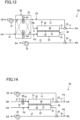
- a humidifier (61) is provided in a flow path (a first inside air duct (11)) on an upstream side of a permeable film (35) in an inside air passage (P1).
- the humidifier (61) is formed so as to add moisture to the permeable film (35) of a permeable film unit (30).
- types of the humidifier (61) include a type in which moisture is evaporated and air is humidified (for example, a boiling type, an ultrasonic type, and a spray type); and a type in which moisture is separated from, for example, an adsorbent, a sorption, or an absorbent and is sent into the air to humidify the air.
- the humidifier (61) is configured to make the humidification capability adjustable. Specifically, a controller (50) allows the humidifier (61) to be switched between operation/stop, and allows the amount of discharge of moisture into air to be finely adjusted during the operation of the humidifier (61). For example, the humidification capability of the humidifier (61) is adjusted in accordance with the detected concentration provided by a carbon dioxide concentration sensor (40).
- the humidifier (61) For example, during the winter season, by operating the humidifier (61), it is possible to humidify air that is supplied into an indoor space (R) from the inside air passage (P1). That is, the humidifier (61) is used not only to humidify the permeable film (35) but also to humidify the indoor space (R) to be ventilated.
- a dehumidifier (62) is provided in a flow path (an air supply duct (13)) on a downstream side of a permeable film (35) in an inside air passage (P1).
- the dehumidifier (62) is formed so as to dehumidify air flowing in the air supply duct (13).
- types of the dehumidifier (62) include a type in which moisture is fixed to, for example, an adsorbent or a sorption; and a type in which moisture is absorbed by an absorbent.
- the dehumidifier (62) may also be of a type in which air is cooled down to a temperature less than or equal to the dew point temperature to remove the moisture in the air as condensed water.
- the humidifier (61) and the dehumidifier (62) according to Modification 2 are incorporated in a humidifier/dehumidifier unit (63).
- the humidifier/dehumidifier unit (63) includes a water supplying section (64) that sends moisture taken away from the air by the dehumidifier (62) into the humidifier (61). That is, the humidifier (61) is formed so as to make use of the moisture removed by the dehumidifier (62) as humidifying water. Therefore, in the humidifier/dehumidifier unit (63), the amount of water that is separately supplied to the humidifier (61) is zero or can be reduced.
- a humidifier/dehumidifier rotor (65) is provided in both a flow path (a first inside air duct (11)) on an upstream side of a permeable film (35) in an inside air passage (P1) and a flow path (an air supply duct (13)) on a downstream side of the permeable film (35) in the inside air passage (P1).
- the humidifier/dehumidifier rotor (65) includes a rotor main body (66) disposed in both the first inside air duct (11) and an air supply duct (13), and a drive shaft (67) that rotationally drives the rotor main body (66).
- the rotor main body (66) carries an adsorbent that is capable of adsorbing and desorbing moisture.
- a desorption region (68) where moisture is discharged into air is formed on a portion of the rotor main body (66) that is positioned on the side of the first inside air duct (11).
- An adsorption region (69) where moisture in air is adsorbed is formed on a portion of the rotor main body (66) that is positioned on the side of the air supply duct (13).
- a heating section for example, a heater (70)
- the desorption region (68) forms a humidifier for adding moisture to the permeable film (35).
- the adsorption region (69) forms a dehumidifier for dehumidifying air that is supplied into an indoor space (R).
- the moisture in the air is adsorbed by the adsorbent, and the air is dehumidified.
- the humidifier/dehumidifier rotor (65) by rotationally driving the rotor main body (66) by the drive shaft (67), the adsorbent that has adsorbed the moisture in the adsorption region (69) is displaced to the desorption region (68).
- the humidifier/dehumidifier rotor (65) is capable of continuously and at the same time humidifying the air in the first inside air duct (11) and dehumidifying the air in the air supply duct (13).
- a humidity control unit (80) is provided in both a first inside air duct (11) and an air supply duct (13).
- the humidity control unit (80) includes a hollow humidity-control casing (81) and a first adsorption heat exchanger (83) and a second adsorption heat exchanger (84) that are accommodated inside the humidity-control casing (81).
- the first adsorption heat exchanger (83) and the second adsorption heat exchanger (84) are heat exchangers that carry an adsorbent (to be exact, also called a sorption), and are connected to a refrigerant circuit filled with a refrigerant.
- a compressor, an expansion valve, and a four-way switching valve are connected (not shown) to the refrigerant circuit, and the circulation direction of the refrigerant is reversible in accordance with the state of the four-way switching valve. Therefore, in the refrigerant circuit, a first refrigeration cycle and a second refrigeration cycle are performed by switching between the cycles.
- the refrigerant evaporates at the first adsorption heat exchanger (83).
- the refrigerant is evaporated at the second adsorption heat exchanger (84).
- An air flow path switching section (not shown) is provided inside the humidity-control casing (81).
- the air flow path switching section includes a plurality of air flow paths and a damper that switches a disconnection state of each air flow path.
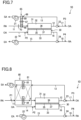
- the state of the air flow path switching section is switched between a first state in which a first air flow path (a flow path schematically shown by a solid line in Fig. 8 ) is formed inside the humidity-control casing (81) and a second state in which a second air flow path (a flow path schematically shown by a broken line in Fig. 8 ) is formed inside the humidity-control casing (81).
- a first operation and a second operation below are alternately and repeatedly executed each time a predetermined time (a few minutes) has elapsed.
- the first air flow path is formed. Therefore, air that has flown into the humidity-control casing (81) from the first inside air duct (11) flows in the second adsorption heat exchanger (84) that becomes a condenser.
- the second adsorption heat exchanger (84) an adsorbent is heated by a condensed refrigerant and moisture adsorbed by the adsorbent is discharged into air. Consequently, in the second adsorption heat exchanger (84), the air is humidified. The humidified air is sent into the first passage (32) of the permeable film unit (30) and adds moisture to the permeable film (35).
- the second adsorption heat exchanger (84) that becomes a condenser functions as a humidifier
- the first adsorption heat exchanger (83) that becomes an evaporator functions as a dehumidifier.
- the second air flow path is formed. Therefore, air that has flown into the humidity-control casing (81) from the first inside air duct (11) flows in the first adsorption heat exchanger (83) that becomes a condenser.
- the first adsorption heat exchanger (83) an adsorbent is heated by a refrigerant that is condensed and moisture adsorbed by the adsorbent is discharged into air. Consequently, in the first adsorption heat exchanger (83), the air is humidified. The humidified air is sent into the first passage (32) of the permeable film unit (30) and adds moisture to the permeable film (35).
- the first adsorption heat exchanger (83) that becomes a condenser functions as a humidifier
- the second adsorption heat exchanger (84) that becomes an evaporator functions as a dehumidifier.
- a humidifier (61) is provided on an upstream side of a permeable film (35) in an outside air passage (P2).
- the humidifier (61) is formed so as to add moisture to the permeable film (35) of a permeable film unit (30).
- the outdoor air flows in a second passage (33) of the permeable film unit (30). Therefore, moisture is added to the permeable film (35) (more exactly, a permeable surface (37) of the permeable film (35)) by the outdoor air to maintain the humid state of the permeable film (35).
- the permeable film (35) the carbon dioxide separation efficiency is increased.
- a dehumidifier (62) is provided in a flow path (an air supply duct (13)) on a downstream side of a permeable film (35) in an inside air passage (P1). Therefore, during, for example, the summer season, it is possible to dehumidify air that is supplied into an indoor space (R) and to ensure the comfortableness of the indoor space (R).
- a humidifier/dehumidifier rotor (65) is provided in both a flow path (a first outside air duct (14)) on an upstream side of a permeable film (35) in an outside air passage (P2) and a flow path (an air supply duct (13)) on a downstream side of the permeable film (35) in an inside air passage (P1).
- the structure, operation, and advantageous effects of the humidifier/dehumidifier rotor (65) are the same as those in Modification 4.
- a humidity control unit (80) is provided in both a flow path (a first outside air duct (14)) on an upstream side of a permeable film (35) in an outside air passage (P2) and a flow path (an air supply duct (13)) on a downstream side of the permeable film (35) in an inside air passage (P1).
- the structure, operation, and advantageous effects of the humidity control unit (80) are the same as those in Modification 5.
- a cooling section (85) that cools air is provided in a flow path (a first inside air duct (11)) on an upstream side of a permeable film (35) in an inside air passage (P1).
- the cooling section (85) is formed from, for example, an evaporator connected to a refrigerant circuit.
- indoor air that flows in the first inside air duct (11) is cooled by the cooling section (85), so that the relative humidity of the indoor air is increased.
- Modification 12 shown in Fig. 15 is not according to the invention and differs from the embodiment above in the structure of a permeable film unit (30) and the structures of ducts.
- the permeable film unit (30) is disposed in an outdoor space (O).
- the permeable film unit (30) includes, for example, a cylindrical permeable film (35) and has a first passage (32), which is a part of an inside air passage (P1), formed therein. That is, an inner peripheral surface of the permeable film (35) is a supply surface (36) and an outer peripheral surface of the permeable film (35) is a permeable surface (37).
- An outflow end of an air supply passage (P3) is connected to a downstream side of the permeable film (35) in the inside air passage (P1).
- An air supply fan (an inside air fan) (not shown) is provided on a downstream side of a connection portion of the air supply passage (P3) in the inside air passage (P1).
- An air-supply-side adjusting mechanism (23) that is the same as that in the embodiment above is provided at a connection portion where the inside air passage (P1) and the air supply passage (P3) are connected to each other.
- a ventilation unit (10) includes a discharge passage (P4) including an inflow end that communicates with an indoor space (R) and an outflow end that communicates with an outdoor space (O).
- a discharge fan (not shown) is provided in the discharge passage (P4).
- the air-supply-side adjusting mechanism (23) is in the first state. Therefore, in the first ventilation operation, outdoor air is supplied into the indoor space (R) via the air supply passage (P3) and the inside air passage (P1) without the permeable film unit (30) being operated. At the same time, indoor air is discharged into the outdoor space (O) via the discharge passage (P4).
- the air-supply-side adjusting mechanism (23) is in the second state. Therefore, in the second ventilation operation, indoor air flows into the inside air passage (P1) and flows in the first passage (32) of the permeable film unit (30). In the permeable film unit (30), due to the partial pressure difference between carbon dioxide in the indoor air that flows in the first passage (32) and carbon dioxide in outdoor air surrounding the permeable film (35), the carbon dioxide in the indoor air passes through the permeable film (35) and is discharged into the outdoor space (O). After the indoor air from which carbon dioxide has been removed has been mixed with the outdoor air that has been sent from the air supply passage (P3), the indoor air is supplied into the indoor space (R). At the same time, indoor air is discharged into the outdoor space (O) via the discharge passage (P4).
- Modification 13 shown in Fig. 16 is not according to the invention and differs from the embodiment above in the structure of a permeable film unit (30) and the structures of ducts.
- the permeable film unit (30) is disposed in an indoor space (R).
- the permeable film unit (30) includes, for example, a cylindrical permeable film (35) and has a second passage (33), which is a part of an outside air passage (P2), formed therein. That is, an inner peripheral surface of the permeable film (35) is a supply surface (36) and an outer peripheral surface of the permeable film (35) is a permeable surface (37).
- An outflow end of a discharge passage (P4) is connected to a downstream side of the permeable film (35) in the outside air passage (P2).
- a discharge fan an outside air fan (not shown) is provided on a downstream side of a connection portion of the discharge passage (P4) in the outside air passage (P2).
- a discharge-side adjusting mechanism (24) that is the same as that in the embodiment above is provided at a connection portion where the outside air passage (P2) and the discharge passage (P4) are connected to each other.
- a ventilation unit (10) includes an air supply passage (P3) including an inflow end that communicates with an outdoor space (O) and an outflow end that communicates with the indoor space (R).
- An air supply fan (not shown) is provided in the air supply passage (P3).
- the discharge-side adjusting mechanism (24) is in the second state. Therefore, in the second ventilation operation, outdoor air flows into the outside air passage (P2) and flows in the second passage (33) of the permeable film unit (30). In the permeable film unit (30), due to the partial pressure difference between carbon dioxide in indoor air that flows in the second passage (33) and carbon dioxide in indoor air surrounding the permeable film (35), the carbon dioxide in the indoor air in the indoor space (R) passes through the permeable film (35) and is discharged into the second passage (33).
- Modification 14 shown in Fig. 17 differs from the embodiment above in the structure of a permeable film unit (30).
- the permeable film unit (30) includes a hollow cylindrical separation duct (31) and a plurality of permeable films (35) that are disposed inside the separation duct (31).
- the separation duct (31) has, for example, a vertically long cylindrical shape, and the inside of the separation duct is divided into a first header space (91), a second header space (92), and a center space (93).
- the first header space (91) is formed towards one end (towards the left in Fig. 18 ) of the separation duct (31) in an axial direction.
- the second header space (92) is formed towards the other end (towards the right in Fig. 18 ) of the separation duct (31) in the axial direction.
- the center space (93) is formed between the first header space (91) and the second header space (92).
- a first inflow pipe (94) is connected to one end side of the separation duct (31), and a first outflow pipe (95) is connected to the other end side of the separation duct (31).
- An outflow end of the first inflow pipe (94) communicates with the first header space (91), and an inflow end of the first outflow pipe (95) communicates with the second header space (92).
- a second inflow pipe (96) and a second outflow pipe (97) are connected to a peripheral wall of the separation duct (31).
- the second inflow pipe (96) communicates with a portion towards one end side of the separation duct (31) in the center space (93), and the second outflow pipe (97) communicates with a portion towards the other end side of the separation duct (31) in the center space (93).
- the plurality of permeable films (35) are formed of a vertically long cylindrical hollow fiber membrane. Each permeable film (35) extends in the axial direction of the separation duct (31), and a large portion of each permeable films (35) is positioned in the center space (93). An opening on one end side of each permeable film (35) in the axial direction communicates with the first header space (91). An opening on the other end side of each permeable film (35) in the axial direction communicates with the second header space (92).
- each permeable film (35) After the indoor air from which the carbon dioxide has been removed inside each permeable film (35) has merged at the second header space (92), the indoor air flows in the first outflow pipe (95) and is supplied into an indoor space (R) again.
- the outdoor air to which the carbon dioxide has been discharged in the center space (93) flows in the second outflow pipe (97) and is discharged into an outdoor space (O).
- Modification 15 shown in Fig. 18 differs from the embodiment above in air flow in a structure similar to that of the permeable film unit (30) of Modification 14. Specifically, outdoor air flows in a first inflow pipe (94), a first header space (91), each permeable film (35), a second header space (92), and a first outflow pipe (95) in this order, and is discharged into an outdoor space (O). Indoor air flows in a second inflow pipe (96), a center space (93), and a second outflow pipe (97) in this order, and is supplied into an indoor space (R).
- a permeable film unit (30) of Modification 16 shown in Fig. 19 is formed as a counterflow type. That is, the direction of flow of indoor air flowing along a supply surface (36) of a permeable film (35) and the direction of flow of outdoor air flowing along the permeable film (35) are opposite to each other.
- a ventilation system (S) in Fig. 20 has a structure that is basically the same as the structure in the embodiment above ( Fig. 3 ). That is, the ventilation system (S) includes an inside air passage (P1) having an inflow end and an outflow end that each communicate with an indoor space (R) to be ventilated, and an air supply passage (P3) having an inflow end that communicates with an outdoor space (O) and an outflow end that is connected to a downstream side of a permeable film (35) (a permeable film unit (30)) in the inside air passage (P1).
- the inside air passage (P1) includes inside air introducing paths (11, 12) on an upstream side of a connection portion of the air supply passage (P3) and an inside air supply path (13) on a downstream side of the connection portion of the air supply passage (P3).
- the inside air introducing paths (11, 12) are flow paths including a corresponding one of the first inside air duct (11) and the inside air relay duct (12) of the embodiment above.
- the inside air supply path corresponds to the air supply duct (13) of the embodiment above.
- An air supply fan (21) is disposed on a downstream side of the connection portion of the air supply passage (P3) in the inside air passage (P1) (that is, at the air supply duct (13)).
- the ventilation system (S) includes an outside air passage (P2) having an inflow end and an outflow end that each communicate with the outdoor space (O), and a discharge passage (P4) having an inflow end that communicates with the indoor space (R) and an outflow end that is connected to a downstream side of the permeable film (35) in the outside air passage (P2).
- the outside air passage (P2) includes outside air introducing paths (14, 16) on an upstream side of a connection portion of the discharge passage (P4) and an outside air discharge path (15) on a downstream side of the connection portion of the discharge passage (P4).
- the outside air introducing paths (14, 16) are flow paths including a corresponding one of the first outside air duct (14) and the outside air relay duct (16) of the embodiment above.
- the outside air discharge path (15) corresponds to the discharge duct (15) of the embodiment above.
- a discharge fan (22) is disposed on a downstream side of the connection portion of the discharge passage (P4) in the outside air passage (P2).
- the air-supply-side adjusting mechanism (23) adjusts the flow rate of air that flows in the inside air introducing paths (11, 12) and the flow rate of air that flows in the air supply passage (P3).
- the air flow rates include a zero air flow rate.
- the air-supply-side adjusting mechanism (23) includes a first damper (D1) that is disposed in an inside air introducing path (11, 12) (for example, the inside air relay duct (12)), and a second damper (D2) that is disposed in the air supply passage (P3) (the second outside air duct (17)).
- the first damper (D1) and the second damper (D2) of this example are formed so as to open or close the corresponding air flow path.
- the first damper (D1) and the second damper (D2) may each be a damper that finely changes the opening degree of the corresponding air flow path.
- the air-supply-side adjusting mechanism (23) may be a damper, a flow rate adjusting valve, an on-off valve, and an auxiliary fan that are provided in at least one of the inside air introducing paths (11, 12) and the air supply passage (P3). Even these are capable of adjusting one or both of the flow rate of air that flows in the inside air introducing paths (11, 12) and the flow rate of air that flows in the air supply passage (P3).
- the discharge-side adjusting mechanism (24) adjusts the flow rate of air that flows in the outside air introducing paths (14, 16) and the flow rate of air that flows in the discharge passage (P4).
- the air flow rates include a zero air flow rate.
- the discharge-side adjusting mechanism (24) includes a third damper (D3) that is disposed in an outside air introducing path (14, 16) (for example, the outside air relay duct (16)), and a fourth damper (D4) that is disposed in the discharge passage (P4) (the second inside air duct (18)).
- the third damper (D3) and the fourth damper (D4) of this example are formed so as to open or close the corresponding air flow path.
- the third damper (D3) and the fourth damper (D4) may each be a damper that finely changes the opening degree of the corresponding air flow path.
- the discharge-side adjusting mechanism (24) may be a damper, a flow rate adjusting valve, an on-off valve, and an auxiliary fan that are provided in at least one of the outside air introducing paths (14, 16) and the discharge passage (P4). Even these are capable of adjusting one or both of the flow rate of air that flows in the outside air introducing paths (14, 16) and the flow rate of air that flows in the discharge passage (P4).
- a carbon dioxide concentration sensor (40) that detects the concentration of carbon dioxide is provided in the indoor space (R).
- the carbon dioxide concentration sensor (40) forms a concentration detecting section that detects the concentration of target gas in the permeable film unit (30).
- the ventilation system (S) may include a controller (50) that is a controlling device.
- the controller (50) controls the air-supply-side adjusting mechanism (23) and the discharge-side adjusting mechanism (24) on the basis of the concentration of carbon dioxide detected by the carbon dioxide concentration sensor (40). Specifically, the controlling device (50) switches an open-close state of the first damper (D1), the second damper (D2), the third damper (D3), and the fourth damper (D4).
- the indoor air and the outdoor air are circulated. That is, when the first condition is met, the controlling device (50) causes the air-supply-side adjusting mechanism (23) to be in the first state so that the inside air introducing paths (11, 12) and the inside air supply path (13) communicate with each other and the air supply passage (P3) and the inside air supply path (13) are disconnected from each other.
- the first damper (D1) is caused to be in an open state
- the second damper (D2) is caused to be in a closed state.
- the controlling device (50) causes the discharge-side adjusting mechanism (24) to be in the first state so that the outside air introducing paths (14, 16) and the outside air discharge path (15) communicate with each other and the discharge passage (P4) and the outside air discharge path (15) are disconnected from each other.
- the third damper (D3) is caused to be in an open state and the fourth damper (D4) is caused to be in a closed state.
- the indoor air circulates in the indoor space (R) via the inside air passage (P1) and the outdoor air circulates in the outdoor space (O) via the outside air passage (P2).
- carbon dioxide in the indoor air is added to the outdoor air via the permeable film (35).
- the indoor air is discharged out of a room to perform a ventilation operation in which outdoor air is supplied into the room. That is, when the second condition is met, the controlling device (50) causes the air-supply-side adjusting mechanism (23) to be in the second state so that the inside air introducing paths (11, 12) and the inside air supply path (13) are disconnected from each other and the air supply passage (P3) and the inside air supply path (13) communicate with each other.
- a predetermined value for example, 1000 ppm
- the first damper (D1) is caused to be in a closed state
- the second damper (D2) is caused to be in an open state.
- the controlling device (50) causes the discharge-side adjusting mechanism (24) to be in the second state so that the outside air introducing paths (14, 16) and the outside air discharge path (15) are disconnected from each other and the discharge passage (P4) and the outside air discharge path (15) communicate with each other.
- the third damper (D3) is caused to be in a closed state and the fourth damper (D4) is caused to be in an open state.
- the indoor air is discharged out of the room without passing through the permeable film unit (30) and the outdoor air is supplied into the room without passing through the permeable film unit (30).
- the indoor space (R) is positively ventilated, it is possible to quickly reduce the concentration of carbon dioxide in the indoor air.
- the ventilation system (S) may be one in which one indoor room (R) is defined as a room to be ventilated and one permeable film unit (30) corresponding to the one indoor space (R) is provided.
- one permeable film unit (30) may one for a plurality of indoor spaces (R) to be ventilated.
- the permeable film (35) having the form above may be formed of a material that allows a volatile organic compound (VOC) to pass therethrough, or a material that allows both carbon dioxide and a volatile organic compound (VOC) to pass therethrough.
- a sensor that detects the concentration of a volatile organic compound may be used.
- the humidifier (61) may be one that directly adds moisture to a surface of the permeable film (35).
- the present invention is useful for a ventilation system.
Landscapes
- Engineering & Computer Science (AREA)
- Chemical & Material Sciences (AREA)
- Combustion & Propulsion (AREA)
- Mechanical Engineering (AREA)
- General Engineering & Computer Science (AREA)
- General Chemical & Material Sciences (AREA)
- Chemical Kinetics & Catalysis (AREA)
- Analytical Chemistry (AREA)
- Oil, Petroleum & Natural Gas (AREA)
- Separation Using Semi-Permeable Membranes (AREA)
- Air Conditioning Control Device (AREA)
- Ventilation (AREA)
- Drying Of Gases (AREA)
Claims (9)
- Système de ventilation comprenant :un conduit d'air intérieur (P1) doté d'une extrémité d'admission et d'une extrémité d'évacuation, chaque extrémité étant adaptée respectivement pour communiquer avec un espace intérieur (R) devant être ventilé ;au moins un dispositif à film perméable (30) dans le conduit d'air d'intérieur (P1), l'au moins un dispositif à film perméable (30) comprenant un conduit de séparation (31) et un film perméable (35) permettant le passage par celui-ci d'un gaz cible, et configuré pour évacuer le gaz cible qui est passé, à travers le film perméable (35), dans l'air ambiant, le gaz cible contenant au moins un du gaz carbonique et d'un composé organique volatil dans l'air d'intérieur, s'écoulant dans le conduit d'air intérieur (P1) ; etun conduit d'arrivée d'air (P3) doté d'une extrémité d'admission adaptée pour communiquer avec un espace extérieur (O), et d'une extrémité d'évacuation raccordée à un côté en aval du dispositif à film perméable (30) dans le conduit d'air intérieur (P1),le film perméable (35) subdivisant l'espace intérieur du conduit de séparation (31) en un premier conduit (32) et un deuxième conduit (33),le conduit d'arrivée d'air (P3) étant configuré pour mélanger l'air ambiant, évacué par le conduit d'arrivée d'air (P3), avec de l'air évacué par le premier conduit (32).
- Système de ventilation selon la revendication 1, comprenantun conduit d'air ambiant (P2) doté d'une extrémité d'admission et d'une extrémité d'évacuation, chaque extrémité étant adaptée respectivement pour communiquer avec l'espace extérieur (O),le film perméable (35) étant agencé de façon à séparer l'un de l'autre le conduit d'air intérieur (P1) et le conduit d'air ambiant (P2).
- Système de ventilation selon la revendication 2, comprenant
un conduit d'évacuation (P4) doté d'une extrémité d'admission communiquant avec l'espace d'intérieur (R) et d'une extrémité d'évacuation raccordée à un côté en aval du film perméable (35) dans le conduit d'air ambiant (P2). - Système de ventilation, comprenantun conduit d'air ambiant (P2) doté d'une extrémité d'admission et d'une extrémité d'évacuation, chaque extrémité étant adaptée respectivement pour communiquer avec l'espace extérieur (O) ;au moins un dispositif à film perméable (30) dans le conduit d'air ambiant (P2), l'au moins un dispositif à film perméable (30) comprenant un conduit de séparation (31) et un film perméable (35) permettant le passage par celui-ci d'un gaz cible, et configuré pour évacuer le gaz cible, qui est passé à travers le film perméable (35), dans l'air ambiant du conduit d'air ambiant (P2), le gaz cible contenant au moins un du gaz carbonique et d'un composé organique volatil dans l'air d'intérieur d'un espace d'intérieur (R) à ventiler, le film perméable (35) subdivisant l'espace intérieur du conduit de séparation (31) en un premier conduit (32) et un deuxième conduit (33) ; etun conduit d'évacuation (P4) doté d'une extrémité d'admission adaptée pour communiquer avec l'espace d'intérieur (R) et d'une extrémité d'évacuation raccordée à un côté en aval du dispositif à film perméable (30) dans le conduit d'air ambiant (P2),l'extrémité d'admission du conduit d'évacuation (P4) étant adaptée pour déboucher dans l'espace d'intérieur (R).
- Système de ventilation selon la revendication 4, comprenantun conduit d'air intérieur (P1) doté d'une extrémité d'admission et d'une extrémité d'évacuation, chaque extrémité étant adaptée respectivement pour communiquer avec l'espace intérieur (R) à ventiler,le film perméable (35) étant agencé de façon à séparer l'un de l'autre le conduit d'air intérieur (P1) et le conduit d'air ambiant (P2).
- Système de ventilation selon une quelconque des revendications 1 à 3, comprenant :
un ventilateur d'air d'intérieur (21) disposé sur un côté en aval d'une partie de raccordement du conduit d'arrivée d'air (P3) dans le conduit d'air intérieur (P1). - Système de ventilation selon une quelconque des revendications 1, 2, 3 et 6,le conduit d'air intérieur (P1) comprenant un chemin d'introduction de l'air d'intérieur (11, 12) sur un côté en amont d'une partie de raccordement du conduit d'arrivée d'air (P3), et un chemin d'alimentation en air d'intérieur (13) sur un côté en aval d'une partie de raccordement du conduit d'arrivée d'air (P3), etle système de ventilation comprenant un mécanisme d'ajustement du côté d'alimentation en air (23) configuré pour ajuster un d'un débit d'air s'écoulant dans le chemin d'introduction de l'air d'intérieur (11, 12) et d'un débit d'air s'écoulant dans le conduit d'arrivée d'air (P3), ou les deux.
- Système de ventilation selon la revendication 7, comprenantune section de détection de la concentration (40), configurée pour détecter une concentration d'un gaz cible dans l'air d'intérieur dans l'espace intérieur (R), etun dispositif de régulation (50) configuré pour commander le mécanisme d'ajustement du côté d'alimentation en air (23) sur la base d'une concentration détectée, fournie par la section de détection de la concentration (40).
- Système de ventilation selon une quelconque des revendications 1 à 8, comprenant :
une pluralité de dispositifs à film perméable (30) agencés en correspondance avec une pluralité d'espaces intérieurs (R) à ventiler.
Applications Claiming Priority (2)
| Application Number | Priority Date | Filing Date | Title |
|---|---|---|---|
| JP2017110136 | 2017-06-02 | ||
| PCT/JP2018/021273 WO2018221740A1 (fr) | 2017-06-02 | 2018-06-01 | Système de ventilation |
Publications (3)
| Publication Number | Publication Date |
|---|---|
| EP3617606A1 EP3617606A1 (fr) | 2020-03-04 |
| EP3617606A4 EP3617606A4 (fr) | 2021-01-20 |
| EP3617606B1 true EP3617606B1 (fr) | 2023-12-27 |
Family
ID=64456546
Family Applications (1)
| Application Number | Title | Priority Date | Filing Date |
|---|---|---|---|
| EP18809173.0A Active EP3617606B1 (fr) | 2017-06-02 | 2018-06-01 | Système de ventilation |
Country Status (5)
| Country | Link |
|---|---|
| US (1) | US11465095B2 (fr) |
| EP (1) | EP3617606B1 (fr) |
| JP (1) | JP6447770B2 (fr) |
| CN (1) | CN110709643B (fr) |
| WO (1) | WO2018221740A1 (fr) |
Families Citing this family (16)
| Publication number | Priority date | Publication date | Assignee | Title |
|---|---|---|---|---|
| JP6687063B2 (ja) | 2018-07-11 | 2020-04-22 | ダイキン工業株式会社 | 換気システム |
| JP6609386B1 (ja) | 2019-02-05 | 2019-11-20 | 川崎重工業株式会社 | 空気浄化システム |
| KR102369029B1 (ko) * | 2019-09-17 | 2022-02-28 | 한양대학교 산학협력단 | 공조 시스템 및 그의 제어방법 |
| JP6707169B1 (ja) * | 2019-10-03 | 2020-06-10 | 川崎重工業株式会社 | ガス分離膜モジュール |
| KR102232441B1 (ko) * | 2020-08-27 | 2021-03-26 | 한국건설기술연구원 | 육구 공조기 |
| JP7680709B2 (ja) * | 2021-05-26 | 2025-05-21 | 日産自動車株式会社 | 車両用除湿装置 |
| JP7252293B1 (ja) | 2021-09-28 | 2023-04-04 | 川崎重工業株式会社 | 空気浄化システム |
| EP4419847A4 (fr) * | 2021-10-22 | 2025-09-03 | Arcelik As | Purificateur d'air comprenant une membrane |
| CN114165885B (zh) * | 2021-12-17 | 2023-03-24 | 广东美的制冷设备有限公司 | 一种多联机新风系统控制方法、装置、空调器及存储介质 |
| WO2023234131A1 (fr) * | 2022-05-31 | 2023-12-07 | 三菱電機株式会社 | Dispositif d'adsorption de co2 |
| EP4558772A1 (fr) * | 2022-07-18 | 2025-05-28 | Baryon Inc. | Échangeur de chaleur amélioré avec des générateurs thermoélectriques |
| JP2024047604A (ja) * | 2022-09-27 | 2024-04-08 | パナソニックIpマネジメント株式会社 | Co2分離システム |
| JP2024139866A (ja) * | 2023-03-28 | 2024-10-10 | パナソニックIpマネジメント株式会社 | Co2分離システム |
| JP2025151397A (ja) * | 2024-03-28 | 2025-10-09 | パナソニックIpマネジメント株式会社 | Co2分離システム |
| WO2026059604A1 (fr) * | 2024-09-11 | 2026-03-19 | W. L. Gore & Associates, Inc. | Systèmes et procédés de déshumidification |
| CN119436342B (zh) * | 2024-12-10 | 2025-10-28 | 江苏齐力涂装环境工程有限公司 | 一种打磨喷漆室空气循环控制系统 |
Family Cites Families (10)
| Publication number | Priority date | Publication date | Assignee | Title |
|---|---|---|---|---|
| JP2006105426A (ja) * | 2004-09-30 | 2006-04-20 | Max Co Ltd | 換気装置及び建物 |
| US7434413B2 (en) * | 2005-01-10 | 2008-10-14 | Honeywell International Inc. | Indoor air quality and economizer control methods and controllers |
| JP2006275487A (ja) | 2005-03-30 | 2006-10-12 | Shimizu Corp | 炭酸ガス除去空調システム |
| JP5281970B2 (ja) | 2009-06-30 | 2013-09-04 | 信越ポリマー株式会社 | 空調システム |
| JP2012011878A (ja) * | 2010-06-30 | 2012-01-19 | Denso Corp | 空気浄化装置 |
| JP2012032138A (ja) * | 2010-06-30 | 2012-02-16 | Denso Corp | 換気装置 |
| JP5849889B2 (ja) | 2011-08-02 | 2016-02-03 | 株式会社デンソー | 空調システム |
| CN104379234B (zh) * | 2012-05-22 | 2018-02-27 | 恩沃德系统公司 | 对室内空气的洗涤的吸附剂的高效利用 |
| JP2014129998A (ja) * | 2012-11-30 | 2014-07-10 | Akira Ishibashi | 壁ならびに高清浄部屋システムおよびその製造方法ならびに建築物 |
| JP5668766B2 (ja) * | 2013-02-07 | 2015-02-12 | ダイキン工業株式会社 | 換気装置 |
-
2018
- 2018-06-01 US US16/618,008 patent/US11465095B2/en active Active
- 2018-06-01 JP JP2018106238A patent/JP6447770B2/ja active Active
- 2018-06-01 WO PCT/JP2018/021273 patent/WO2018221740A1/fr not_active Ceased
- 2018-06-01 CN CN201880035683.0A patent/CN110709643B/zh active Active
- 2018-06-01 EP EP18809173.0A patent/EP3617606B1/fr active Active
Also Published As
| Publication number | Publication date |
|---|---|
| US11465095B2 (en) | 2022-10-11 |
| CN110709643A (zh) | 2020-01-17 |
| EP3617606A1 (fr) | 2020-03-04 |
| WO2018221740A1 (fr) | 2018-12-06 |
| CN110709643B (zh) | 2022-02-18 |
| EP3617606A4 (fr) | 2021-01-20 |
| JP2018204946A (ja) | 2018-12-27 |
| JP6447770B2 (ja) | 2019-01-09 |
| US20200179867A1 (en) | 2020-06-11 |
Similar Documents
| Publication | Publication Date | Title |
|---|---|---|
| EP3617606B1 (fr) | Système de ventilation | |
| US10012401B2 (en) | Method and apparatus for conditioning air | |
| EP2224182B1 (fr) | Dispositif de commande de l'humidité | |
| CN103717976B (zh) | 调湿装置以及空气调节系统 | |
| KR100711625B1 (ko) | 공기조화장치 | |
| EP3961120B1 (fr) | Unité de régulation d'humidité et système de régulation d'humidité | |
| TW201719083A (zh) | 空調系統 | |
| EP1895244A1 (fr) | Systeme de climatisation | |
| JP4857901B2 (ja) | デシカント空調システム | |
| WO2010100739A1 (fr) | Climatiseur | |
| EP2693132B1 (fr) | Dispositif de ventilation à régulation d'humidité | |
| CN110678698B (zh) | 空调方法和装置 | |
| JP2010084970A (ja) | 空調システムおよび熱交換ユニット | |
| JP4802647B2 (ja) | 除湿装置 | |
| US20250207791A1 (en) | Multi-Stage Liquid Desiccant Dehumidification Systems and Methods | |
| JP5071566B2 (ja) | 調湿装置 | |
| KR20230090429A (ko) | 공기조화장치 | |
| JP2005249359A (ja) | 高温空調システム | |
| HK1190782A (en) | Method and apparatus for conditioning air |
Legal Events
| Date | Code | Title | Description |
|---|---|---|---|
| STAA | Information on the status of an ep patent application or granted ep patent |
Free format text: STATUS: THE INTERNATIONAL PUBLICATION HAS BEEN MADE |
|
| PUAI | Public reference made under article 153(3) epc to a published international application that has entered the european phase |
Free format text: ORIGINAL CODE: 0009012 |
|
| STAA | Information on the status of an ep patent application or granted ep patent |
Free format text: STATUS: REQUEST FOR EXAMINATION WAS MADE |
|
| 17P | Request for examination filed |
Effective date: 20191121 |
|
| AK | Designated contracting states |
Kind code of ref document: A1 Designated state(s): AL AT BE BG CH CY CZ DE DK EE ES FI FR GB GR HR HU IE IS IT LI LT LU LV MC MK MT NL NO PL PT RO RS SE SI SK SM TR |
|
| AX | Request for extension of the european patent |
Extension state: BA ME |
|
| DAV | Request for validation of the european patent (deleted) | ||
| DAX | Request for extension of the european patent (deleted) | ||
| REG | Reference to a national code |
Ref country code: DE Ref legal event code: R079 Ref document number: 602018063306 Country of ref document: DE Free format text: PREVIOUS MAIN CLASS: F24F0007000000 Ipc: F24F0003160000 Ref country code: DE Ref legal event code: R079 Free format text: PREVIOUS MAIN CLASS: F24F0007000000 Ipc: F24F0003160000 |
|
| A4 | Supplementary search report drawn up and despatched |
Effective date: 20201223 |
|
| RIC1 | Information provided on ipc code assigned before grant |
Ipc: F24F 7/06 20060101ALI20201217BHEP Ipc: B01D 53/22 20060101ALI20201217BHEP Ipc: F24F 3/16 20060101AFI20201217BHEP Ipc: F24F 7/08 20060101ALI20201217BHEP Ipc: B01D 53/26 20060101ALI20201217BHEP |
|
| STAA | Information on the status of an ep patent application or granted ep patent |
Free format text: STATUS: EXAMINATION IS IN PROGRESS |
|
| 17Q | First examination report despatched |
Effective date: 20220420 |
|
| RAP3 | Party data changed (applicant data changed or rights of an application transferred) |
Owner name: DAIKIN INDUSTRIES, LTD. |
|
| P01 | Opt-out of the competence of the unified patent court (upc) registered |
Effective date: 20230525 |
|
| RIC1 | Information provided on ipc code assigned before grant |
Ipc: B01D 53/26 20060101ALI20230728BHEP Ipc: B01D 53/22 20060101ALI20230728BHEP Ipc: F24F 8/158 20210101ALI20230728BHEP Ipc: F24F 8/15 20210101ALI20230728BHEP Ipc: F24F 8/10 20210101ALI20230728BHEP Ipc: F24F 7/003 20210101ALI20230728BHEP Ipc: F24F 7/08 20060101ALI20230728BHEP Ipc: F24F 7/06 20060101ALI20230728BHEP Ipc: F24F 3/16 20060101AFI20230728BHEP |
|
| GRAP | Despatch of communication of intention to grant a patent |
Free format text: ORIGINAL CODE: EPIDOSNIGR1 |
|
| STAA | Information on the status of an ep patent application or granted ep patent |
Free format text: STATUS: GRANT OF PATENT IS INTENDED |
|
| INTG | Intention to grant announced |
Effective date: 20230922 |
|
| GRAS | Grant fee paid |
Free format text: ORIGINAL CODE: EPIDOSNIGR3 |
|
| GRAA | (expected) grant |
Free format text: ORIGINAL CODE: 0009210 |
|
| STAA | Information on the status of an ep patent application or granted ep patent |
Free format text: STATUS: THE PATENT HAS BEEN GRANTED |
|
| AK | Designated contracting states |
Kind code of ref document: B1 Designated state(s): AL AT BE BG CH CY CZ DE DK EE ES FI FR GB GR HR HU IE IS IT LI LT LU LV MC MK MT NL NO PL PT RO RS SE SI SK SM TR |
|
| REG | Reference to a national code |
Ref country code: GB Ref legal event code: FG4D |
|
| REG | Reference to a national code |
Ref country code: CH Ref legal event code: EP |
|
| REG | Reference to a national code |
Ref country code: DE Ref legal event code: R096 Ref document number: 602018063306 Country of ref document: DE |
|
| REG | Reference to a national code |
Ref country code: IE Ref legal event code: FG4D |
|
| PG25 | Lapsed in a contracting state [announced via postgrant information from national office to epo] |
Ref country code: GR Free format text: LAPSE BECAUSE OF FAILURE TO SUBMIT A TRANSLATION OF THE DESCRIPTION OR TO PAY THE FEE WITHIN THE PRESCRIBED TIME-LIMIT Effective date: 20240328 |
|
| REG | Reference to a national code |
Ref country code: LT Ref legal event code: MG9D |
|
| PG25 | Lapsed in a contracting state [announced via postgrant information from national office to epo] |
Ref country code: LT Free format text: LAPSE BECAUSE OF FAILURE TO SUBMIT A TRANSLATION OF THE DESCRIPTION OR TO PAY THE FEE WITHIN THE PRESCRIBED TIME-LIMIT Effective date: 20231227 |
|
| PG25 | Lapsed in a contracting state [announced via postgrant information from national office to epo] |
Ref country code: ES Free format text: LAPSE BECAUSE OF FAILURE TO SUBMIT A TRANSLATION OF THE DESCRIPTION OR TO PAY THE FEE WITHIN THE PRESCRIBED TIME-LIMIT Effective date: 20231227 |
|
| PG25 | Lapsed in a contracting state [announced via postgrant information from national office to epo] |
Ref country code: LT Free format text: LAPSE BECAUSE OF FAILURE TO SUBMIT A TRANSLATION OF THE DESCRIPTION OR TO PAY THE FEE WITHIN THE PRESCRIBED TIME-LIMIT Effective date: 20231227 Ref country code: GR Free format text: LAPSE BECAUSE OF FAILURE TO SUBMIT A TRANSLATION OF THE DESCRIPTION OR TO PAY THE FEE WITHIN THE PRESCRIBED TIME-LIMIT Effective date: 20240328 Ref country code: FI Free format text: LAPSE BECAUSE OF FAILURE TO SUBMIT A TRANSLATION OF THE DESCRIPTION OR TO PAY THE FEE WITHIN THE PRESCRIBED TIME-LIMIT Effective date: 20231227 Ref country code: ES Free format text: LAPSE BECAUSE OF FAILURE TO SUBMIT A TRANSLATION OF THE DESCRIPTION OR TO PAY THE FEE WITHIN THE PRESCRIBED TIME-LIMIT Effective date: 20231227 Ref country code: BG Free format text: LAPSE BECAUSE OF FAILURE TO SUBMIT A TRANSLATION OF THE DESCRIPTION OR TO PAY THE FEE WITHIN THE PRESCRIBED TIME-LIMIT Effective date: 20240327 |
|
| REG | Reference to a national code |
Ref country code: NL Ref legal event code: MP Effective date: 20231227 |
|
| REG | Reference to a national code |
Ref country code: AT Ref legal event code: MK05 Ref document number: 1644855 Country of ref document: AT Kind code of ref document: T Effective date: 20231227 |
|
| PG25 | Lapsed in a contracting state [announced via postgrant information from national office to epo] |
Ref country code: NL Free format text: LAPSE BECAUSE OF FAILURE TO SUBMIT A TRANSLATION OF THE DESCRIPTION OR TO PAY THE FEE WITHIN THE PRESCRIBED TIME-LIMIT Effective date: 20231227 |
|
| PG25 | Lapsed in a contracting state [announced via postgrant information from national office to epo] |
Ref country code: SE Free format text: LAPSE BECAUSE OF FAILURE TO SUBMIT A TRANSLATION OF THE DESCRIPTION OR TO PAY THE FEE WITHIN THE PRESCRIBED TIME-LIMIT Effective date: 20231227 Ref country code: RS Free format text: LAPSE BECAUSE OF FAILURE TO SUBMIT A TRANSLATION OF THE DESCRIPTION OR TO PAY THE FEE WITHIN THE PRESCRIBED TIME-LIMIT Effective date: 20231227 Ref country code: NO Free format text: LAPSE BECAUSE OF FAILURE TO SUBMIT A TRANSLATION OF THE DESCRIPTION OR TO PAY THE FEE WITHIN THE PRESCRIBED TIME-LIMIT Effective date: 20240327 Ref country code: NL Free format text: LAPSE BECAUSE OF FAILURE TO SUBMIT A TRANSLATION OF THE DESCRIPTION OR TO PAY THE FEE WITHIN THE PRESCRIBED TIME-LIMIT Effective date: 20231227 Ref country code: LV Free format text: LAPSE BECAUSE OF FAILURE TO SUBMIT A TRANSLATION OF THE DESCRIPTION OR TO PAY THE FEE WITHIN THE PRESCRIBED TIME-LIMIT Effective date: 20231227 Ref country code: HR Free format text: LAPSE BECAUSE OF FAILURE TO SUBMIT A TRANSLATION OF THE DESCRIPTION OR TO PAY THE FEE WITHIN THE PRESCRIBED TIME-LIMIT Effective date: 20231227 |
|
| PG25 | Lapsed in a contracting state [announced via postgrant information from national office to epo] |
Ref country code: IS Free format text: LAPSE BECAUSE OF FAILURE TO SUBMIT A TRANSLATION OF THE DESCRIPTION OR TO PAY THE FEE WITHIN THE PRESCRIBED TIME-LIMIT Effective date: 20240427 |
|
| PG25 | Lapsed in a contracting state [announced via postgrant information from national office to epo] |
Ref country code: AT Free format text: LAPSE BECAUSE OF FAILURE TO SUBMIT A TRANSLATION OF THE DESCRIPTION OR TO PAY THE FEE WITHIN THE PRESCRIBED TIME-LIMIT Effective date: 20231227 Ref country code: CZ Free format text: LAPSE BECAUSE OF FAILURE TO SUBMIT A TRANSLATION OF THE DESCRIPTION OR TO PAY THE FEE WITHIN THE PRESCRIBED TIME-LIMIT Effective date: 20231227 |
|
| PG25 | Lapsed in a contracting state [announced via postgrant information from national office to epo] |
Ref country code: SK Free format text: LAPSE BECAUSE OF FAILURE TO SUBMIT A TRANSLATION OF THE DESCRIPTION OR TO PAY THE FEE WITHIN THE PRESCRIBED TIME-LIMIT Effective date: 20231227 |
|
| PG25 | Lapsed in a contracting state [announced via postgrant information from national office to epo] |
Ref country code: SM Free format text: LAPSE BECAUSE OF FAILURE TO SUBMIT A TRANSLATION OF THE DESCRIPTION OR TO PAY THE FEE WITHIN THE PRESCRIBED TIME-LIMIT Effective date: 20231227 Ref country code: SK Free format text: LAPSE BECAUSE OF FAILURE TO SUBMIT A TRANSLATION OF THE DESCRIPTION OR TO PAY THE FEE WITHIN THE PRESCRIBED TIME-LIMIT Effective date: 20231227 Ref country code: RO Free format text: LAPSE BECAUSE OF FAILURE TO SUBMIT A TRANSLATION OF THE DESCRIPTION OR TO PAY THE FEE WITHIN THE PRESCRIBED TIME-LIMIT Effective date: 20231227 Ref country code: IT Free format text: LAPSE BECAUSE OF FAILURE TO SUBMIT A TRANSLATION OF THE DESCRIPTION OR TO PAY THE FEE WITHIN THE PRESCRIBED TIME-LIMIT Effective date: 20231227 Ref country code: IS Free format text: LAPSE BECAUSE OF FAILURE TO SUBMIT A TRANSLATION OF THE DESCRIPTION OR TO PAY THE FEE WITHIN THE PRESCRIBED TIME-LIMIT Effective date: 20240427 Ref country code: EE Free format text: LAPSE BECAUSE OF FAILURE TO SUBMIT A TRANSLATION OF THE DESCRIPTION OR TO PAY THE FEE WITHIN THE PRESCRIBED TIME-LIMIT Effective date: 20231227 Ref country code: CZ Free format text: LAPSE BECAUSE OF FAILURE TO SUBMIT A TRANSLATION OF THE DESCRIPTION OR TO PAY THE FEE WITHIN THE PRESCRIBED TIME-LIMIT Effective date: 20231227 Ref country code: AT Free format text: LAPSE BECAUSE OF FAILURE TO SUBMIT A TRANSLATION OF THE DESCRIPTION OR TO PAY THE FEE WITHIN THE PRESCRIBED TIME-LIMIT Effective date: 20231227 |
|
| PG25 | Lapsed in a contracting state [announced via postgrant information from national office to epo] |
Ref country code: PL Free format text: LAPSE BECAUSE OF FAILURE TO SUBMIT A TRANSLATION OF THE DESCRIPTION OR TO PAY THE FEE WITHIN THE PRESCRIBED TIME-LIMIT Effective date: 20231227 Ref country code: PT Free format text: LAPSE BECAUSE OF FAILURE TO SUBMIT A TRANSLATION OF THE DESCRIPTION OR TO PAY THE FEE WITHIN THE PRESCRIBED TIME-LIMIT Effective date: 20240429 |
|
| PG25 | Lapsed in a contracting state [announced via postgrant information from national office to epo] |
Ref country code: PT Free format text: LAPSE BECAUSE OF FAILURE TO SUBMIT A TRANSLATION OF THE DESCRIPTION OR TO PAY THE FEE WITHIN THE PRESCRIBED TIME-LIMIT Effective date: 20240429 Ref country code: PL Free format text: LAPSE BECAUSE OF FAILURE TO SUBMIT A TRANSLATION OF THE DESCRIPTION OR TO PAY THE FEE WITHIN THE PRESCRIBED TIME-LIMIT Effective date: 20231227 |
|
| REG | Reference to a national code |
Ref country code: DE Ref legal event code: R097 Ref document number: 602018063306 Country of ref document: DE |
|
| PG25 | Lapsed in a contracting state [announced via postgrant information from national office to epo] |
Ref country code: DK Free format text: LAPSE BECAUSE OF FAILURE TO SUBMIT A TRANSLATION OF THE DESCRIPTION OR TO PAY THE FEE WITHIN THE PRESCRIBED TIME-LIMIT Effective date: 20231227 |
|
| PG25 | Lapsed in a contracting state [announced via postgrant information from national office to epo] |
Ref country code: DK Free format text: LAPSE BECAUSE OF FAILURE TO SUBMIT A TRANSLATION OF THE DESCRIPTION OR TO PAY THE FEE WITHIN THE PRESCRIBED TIME-LIMIT Effective date: 20231227 |
|
| PLBE | No opposition filed within time limit |
Free format text: ORIGINAL CODE: 0009261 |
|
| STAA | Information on the status of an ep patent application or granted ep patent |
Free format text: STATUS: NO OPPOSITION FILED WITHIN TIME LIMIT |
|
| 26N | No opposition filed |
Effective date: 20240930 |
|
| PG25 | Lapsed in a contracting state [announced via postgrant information from national office to epo] |
Ref country code: MC Free format text: LAPSE BECAUSE OF FAILURE TO SUBMIT A TRANSLATION OF THE DESCRIPTION OR TO PAY THE FEE WITHIN THE PRESCRIBED TIME-LIMIT Effective date: 20231227 |
|
| REG | Reference to a national code |
Ref country code: CH Ref legal event code: PL |
|
| PG25 | Lapsed in a contracting state [announced via postgrant information from national office to epo] |
Ref country code: LU Free format text: LAPSE BECAUSE OF NON-PAYMENT OF DUE FEES Effective date: 20240601 |
|
| GBPC | Gb: european patent ceased through non-payment of renewal fee |
Effective date: 20240601 |
|
| PG25 | Lapsed in a contracting state [announced via postgrant information from national office to epo] |
Ref country code: IE Free format text: LAPSE BECAUSE OF NON-PAYMENT OF DUE FEES Effective date: 20240601 |
|
| PG25 | Lapsed in a contracting state [announced via postgrant information from national office to epo] |
Ref country code: BE Free format text: LAPSE BECAUSE OF NON-PAYMENT OF DUE FEES Effective date: 20240630 Ref country code: CH Free format text: LAPSE BECAUSE OF NON-PAYMENT OF DUE FEES Effective date: 20240630 Ref country code: SI Free format text: LAPSE BECAUSE OF FAILURE TO SUBMIT A TRANSLATION OF THE DESCRIPTION OR TO PAY THE FEE WITHIN THE PRESCRIBED TIME-LIMIT Effective date: 20231227 |
|
| PG25 | Lapsed in a contracting state [announced via postgrant information from national office to epo] |
Ref country code: GB Free format text: LAPSE BECAUSE OF NON-PAYMENT OF DUE FEES Effective date: 20240601 |
|
| REG | Reference to a national code |
Ref country code: BE Ref legal event code: MM Effective date: 20240630 |
|
| PGFP | Annual fee paid to national office [announced via postgrant information from national office to epo] |
Ref country code: DE Payment date: 20250429 Year of fee payment: 8 |
|
| PGFP | Annual fee paid to national office [announced via postgrant information from national office to epo] |
Ref country code: FR Payment date: 20250508 Year of fee payment: 8 |
|
| PG25 | Lapsed in a contracting state [announced via postgrant information from national office to epo] |
Ref country code: CY Free format text: LAPSE BECAUSE OF FAILURE TO SUBMIT A TRANSLATION OF THE DESCRIPTION OR TO PAY THE FEE WITHIN THE PRESCRIBED TIME-LIMIT; INVALID AB INITIO Effective date: 20180601 |
|
| PG25 | Lapsed in a contracting state [announced via postgrant information from national office to epo] |
Ref country code: HU Free format text: LAPSE BECAUSE OF FAILURE TO SUBMIT A TRANSLATION OF THE DESCRIPTION OR TO PAY THE FEE WITHIN THE PRESCRIBED TIME-LIMIT; INVALID AB INITIO Effective date: 20180601 |